EP4282377B1 - Visuelle darstellung der erzeugten zahnfleischlinie basierend auf einem 3d-zahnmodell - Google Patents
Visuelle darstellung der erzeugten zahnfleischlinie basierend auf einem 3d-zahnmodell Download PDFInfo
- Publication number
- EP4282377B1 EP4282377B1 EP23202463.8A EP23202463A EP4282377B1 EP 4282377 B1 EP4282377 B1 EP 4282377B1 EP 23202463 A EP23202463 A EP 23202463A EP 4282377 B1 EP4282377 B1 EP 4282377B1
- Authority
- EP
- European Patent Office
- Prior art keywords
- patient
- tooth
- teeth
- image
- gingiva
- Prior art date
- Legal status (The legal status is an assumption and is not a legal conclusion. Google has not performed a legal analysis and makes no representation as to the accuracy of the status listed.)
- Active
Links
Images


Classifications
-
- A—HUMAN NECESSITIES
- A61—MEDICAL OR VETERINARY SCIENCE; HYGIENE
- A61B—DIAGNOSIS; SURGERY; IDENTIFICATION
- A61B34/00—Computer-aided surgery; Manipulators or robots specially adapted for use in surgery
- A61B34/10—Computer-aided planning, simulation or modelling of surgical operations
-
- A—HUMAN NECESSITIES
- A61—MEDICAL OR VETERINARY SCIENCE; HYGIENE
- A61C—DENTISTRY; APPARATUS OR METHODS FOR ORAL OR DENTAL HYGIENE
- A61C7/00—Orthodontics, i.e. obtaining or maintaining the desired position of teeth, e.g. by straightening, evening, regulating, separating, or by correcting malocclusions
- A61C7/002—Orthodontic computer assisted systems
-
- A—HUMAN NECESSITIES
- A61—MEDICAL OR VETERINARY SCIENCE; HYGIENE
- A61C—DENTISTRY; APPARATUS OR METHODS FOR ORAL OR DENTAL HYGIENE
- A61C9/00—Impression cups, i.e. impression trays; Impression methods
- A61C9/004—Means or methods for taking digitized impressions
- A61C9/0046—Data acquisition means or methods
- A61C9/0053—Optical means or methods, e.g. scanning the teeth by a laser or light beam
-
- G—PHYSICS
- G06—COMPUTING OR CALCULATING; COUNTING
- G06T—IMAGE DATA PROCESSING OR GENERATION, IN GENERAL
- G06T19/00—Manipulating 3D models or images for computer graphics
- G06T19/20—Editing of 3D images, e.g. changing shapes or colours, aligning objects or positioning parts
-
- G—PHYSICS
- G06—COMPUTING OR CALCULATING; COUNTING
- G06T—IMAGE DATA PROCESSING OR GENERATION, IN GENERAL
- G06T7/00—Image analysis
- G06T7/0002—Inspection of images, e.g. flaw detection
- G06T7/0012—Biomedical image inspection
-
- A—HUMAN NECESSITIES
- A61—MEDICAL OR VETERINARY SCIENCE; HYGIENE
- A61B—DIAGNOSIS; SURGERY; IDENTIFICATION
- A61B34/00—Computer-aided surgery; Manipulators or robots specially adapted for use in surgery
- A61B34/10—Computer-aided planning, simulation or modelling of surgical operations
- A61B2034/101—Computer-aided simulation of surgical operations
- A61B2034/105—Modelling of the patient, e.g. for ligaments or bones
-
- G—PHYSICS
- G06—COMPUTING OR CALCULATING; COUNTING
- G06T—IMAGE DATA PROCESSING OR GENERATION, IN GENERAL
- G06T2200/00—Indexing scheme for image data processing or generation, in general
- G06T2200/08—Indexing scheme for image data processing or generation, in general involving all processing steps from image acquisition to 3D model generation
-
- G—PHYSICS
- G06—COMPUTING OR CALCULATING; COUNTING
- G06T—IMAGE DATA PROCESSING OR GENERATION, IN GENERAL
- G06T2207/00—Indexing scheme for image analysis or image enhancement
- G06T2207/30—Subject of image; Context of image processing
- G06T2207/30004—Biomedical image processing
- G06T2207/30036—Dental; Teeth
-
- G—PHYSICS
- G06—COMPUTING OR CALCULATING; COUNTING
- G06T—IMAGE DATA PROCESSING OR GENERATION, IN GENERAL
- G06T2210/00—Indexing scheme for image generation or computer graphics
- G06T2210/41—Medical
Definitions
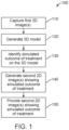
- the technical field relates to digital dental technologies, and more particularly to providing a simulated outcome of dental (e.g., orthodontic, restorative, etc.) treatment by evaluating a two-dimensional (2D) depiction of a patient's untreated teeth against parameters associated with model tooth arches.
- dental e.g., orthodontic, restorative, etc.
- Orthodontic treatment often includes addressing issues with malpositioned teeth and/or jaws and may include diagnosis, prevention, and/or correction of malocclusions.
- a person seeking orthodontic treatment may seek a treatment plan from an orthodontist, such as a professional who has undergone special training after graduating from dental school. Many orthodontic treatment plans include treatment with braces, brackets, wires, and/or polymeric appliances.
- a person seeking orthodontic treatment may have orthodontic appliances adjusted at various times by an orthodontic professional who designs and/or implements the orthodontic appliances.
- US2012/0015316A1 discusses a method and apparatus enabling an orthodontist or a user to create an unified three dimensional virtual craniofacial and dentition model of actual, as-is static and functional anatomy of a patient, from data representing facial bone structure; upper jaw and lower jaw; facial soft tissue; teeth including crowns and roots; information of the position of the roots relative to each other; and relative to the facial bone structure of the patient; obtained by scanning as-is anatomy of craniofacial and dentition structures of the patient with a volume scanning device; and data representing three dimensional virtual models of the patient's upper and lower gingiva, obtained from scanning the patient's upper and lower gingiva either (a) with a volume scanning device, or (a) with a surface scanning device.
- Such craniofacial and dentition models of the patient can be used in optimally planning treatment of a patient.
- US2018/0263733A1 discusses a method that includes: receiving an image of a mouth region of a patient's face; extracting teeth contours within the image of the mouth region of the patient's face; locating a mouth opening within the image of the mouth region of the patient's face; extracting the tooth contours from a 3D model of the patient's teeth; and aligning the tooth contours from the 3D model with the tooth contours of the teeth within the image of the mouth region of the patient's face.
- US2016/0163115A1 discusses how optical scan data including a first set of images representing a first portion of a three-dimensional object is received.
- a processing device receives ultrasound scan data including a second set of three-dimensional images representing a second portion of the three-dimensional object.
- the processing device performs image stitching between the second set of three-dimensional images using the optical scan data.
- the processing device then creates a virtual model of the three-dimensional object based on the stitched second set of three-dimensional images.
- the implementations described use automated agents and/or rules to provide accurate and realistic renderings of simulated outcomes of dental (e.g., orthodontic, restorative, etc.) treatment and/or animations of 3D models that were previously not possible.
- the implementations herein allow people considering and/or undergoing orthodontic treatment the ability to visualize on a computer automatically generated simulated orthodontic treatment outcome simulations, and may inform a person's choices as to whether or not to seek orthodontic treatment in general and/or specific courses of orthodontic treatment.
- the disclosure also relates to systems and methods of accurately and realistically simulating 3D models of teeth in final orthodontic positions in a 2D image of person.
- building the parametric 3D model includes finding edges of teeth and lips in the first 2D image, aligning a parametric tooth model to the edges of the teeth and lips in the first 2D image to determine the case-specific parameters, and storing the case-specific parameters of the parametric tooth model that align the parametric tooth model with the edges of the teeth, gingiva, and lips in the first 2D image.
- the predetermined position is based on an average position of a plurality of previous patients' teeth after dental treatment.
- the computer-implemented method may include iterating through the expectation and maximization steps a first plurality of times to with a first subset of parameters, and after iterating through the expectation and maximization steps the first plurality of times with the first subset of parameters of the 3D parametric model, iterating though the expectation and maximization steps the second plurality of times with the first and second subset of parameters.
- the computer-implement method may include capturing a first 2D image of a patient's face, including their teeth.
- the method may include building a parametric 3D model of the patient's teeth based on the 2D image, the parametric 3D model including case-specific parameters for the shape of at least one of the patient's teeth.
- the method may also include simulating an estimated (e.g., an estimated final) and/or intended (e.g., an intended final) orthodontic position of the patient's teeth by gathering information about one or more model tooth arches that represent smiles without malpositioned teeth and/or jaws, and by rendering the 3D model with the patient's teeth in a predetermined position (e.g., one corresponding to positions of teeth in the model arches) and rendering a second 2D image of the patient's face with teeth in an estimated orthodontic position.
- an estimated e.g., an estimated final
- intended e.g., an intended final
- rendering the second 2D image includes rendering the parametric model of the patient's according to the position of the teeth in the first 2D image, projecting the 2D image onto the rendered parametric model of the patient's according to the position of the teeth in the first 2D image, and mapping the color data from the 2D image to corresponding locations on the 3D model to generate textures for the 3D model, and rendering the second 2D image of the patient's face with teeth in the estimated orthodontic position with the generated textures.
- rendering the second 2D image further includes applying simulated treatments or viewing customizations to the second 2D image.
- the simulated treatments or viewing customizations may include one or more of changing an edge of the gingiva, replacing a tooth, adjusting a jaw position, or adjusting the color data.
- the predetermined position is based on a combination of (e.g., an average) positions of a plurality of previous patients' teeth before orthodontic treatment.
- the method may include finding edges of teeth and lips in the first 2D image, and aligning the parametric tooth model to the edges of the teeth, gingiva, and lips in the first 2D image.
- the first subset of case-specific parameters of the 3D parametric model is one or more of a scale factor, tooth location, and orientation.
- the second subset of parameters of the 3D parametric model are one or more of a tooth shape and tooth location and orientation.
- a computer-implemented method of providing a simulated outcome of orthodontic treatment may include building a 3D parametric model of an arch, the 3D parametric model comprising generic parameters for tooth shape, tooth position, and tooth orientation, capturing a 2D image of a patient, constructing a case-specific 3D parametric model of the patient's teeth from the 2D image, determining the case-specific parameters of the constructed parametric model, rendering the 3D parametric model of the patient's teeth in an estimated and/or intended final position (e.g., without misaligned teeth and/or jaws), and inserting the rendered 3D model into a 2D image of the patient.
- the constructing of a 3D parametric model of the patient's teeth from the 2D image includes: finding edges of teeth, gingiva, and lips in the first 2D image, and aligning the 3D model parametric to the edges of the teeth, gingiva, and lips in the first 2D image.
- the method further comprises applying textures to the rendered 3D parametric model of the patient's teeth in an estimated and/or intended final position (e.g., without misaligned teeth and/or jaws), wherein the textures are derived from the 2D image of the patient.
- scaling factor, ⁇ is applied to the teeth and the arch locations of the teeth to scale the arch from a generic or unit-less representation to a real world scale that represents the actual size and location of the teeth in the arch.
- scaling may be between projected 3D units, for example, millimeter, to images size, for example, pixels.
- an estimated and/or intended outcome of a dental treatment plan on the 3D model is identified to obtain an estimated and/or intended outcome of the orthodontic treatment plan.
- the estimated and/or intended outcome of a dental treatment plan may be based on a parametric model of the patient's teeth at positions indicated based on a predetermined arch model, as discussed with respect to FIGS. 9-11 .
- a predetermined arch model may be based on a mean arch model may be based on a historic mean of collected arch scans or other arch models from patients.
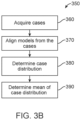
- FIG. 3B illustrates a method of determining generic parameters from historic and/or idealized cases, in accordance with one or more embodiments herein.
- historic and/or idealized cases are acquired.
- the historic and/or idealized cases may be retrieved from a datastore.
- the historic and/or idealized cases may include cases representing previously scanned and segmented arch models.
- the historic and/or idealized cases may represent arch models of treated patients (e.g., of patients who in the past have undergone treatment) and/or idealized arch models representing intended outcomes of various forms of orthodontic treatment.
- the historic and/or idealized cases may represent arch models with idealized arch forms.
- the historic and/or idealized cases may include regions where model arches have teeth that correspond to a location of an implant to be inserted into the arch of a patient.
- the distribution estimation for case-specific parameters are determined. For example, each tooth's relative shape, location, and rotation are determined in order to build a distribution for each case-specific parameter. For example the distribution of the a ⁇ i , the coefficients for the principal components for the surface model of the each respective tooth in all of the retrieved models, is determined.
- the location and orientation of each tooth may be averaged to determine a mean location for each tooth and the orientation of each tooth is averaged to determine a mean orientation for each tooth.
- the mean location and orientation are used to determine T ⁇ C .
- the mean of the distribution of the estimation for case-specific parameters is used as the generic parameters of mean tooth position and mean tooth shape.
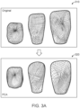
- FIG. 5 depicts a method 500 of generating a parametric model of one or more of a patient's teeth and converting the parametric model of one or more teeth into a 3D model of a dental arch, according to some implementations.
- the method 500 may be used for generating a 3D model of a tooth arch of a patient based on a parametric model of the patient's teeth.
- a mean shape of each tooth is determined.
- the mean shape, S ⁇ C of each tooth is determined.
- the mean shape may be based on the mean shape of a set of arches from historical and/or idealized cases, as discussed herein.
- the mean shape may be rendered, for example, on a screen for viewing by a patient or dental professional.
- mean tooth shapes 512 are rendered for viewing.
- the mean shape may be loaded into memory or retrieved from memory.
- the mean shape may also be initialized as a set of matrices, one for each tooth.
- a principal component analysis shape adjustment is performed on the mean shape of the teeth. This adjustment adjusts the shape of the teeth based on the patient's particular teeth, for example, based on a scan of the patient's teeth, a 2D image, or other imaging technologies, as discussed herein.
- a principal component analysis shape adjustment is performed on the mean shape of the teeth, S ⁇ C .
- the case-specific coefficients for the principal components, a ⁇ i are applied to the principal component, B ⁇ i .
- the adjusted shape may be rendered, for example, on a screen for viewing by a patient or dental professional.
- adjusted tooth shapes 522 are rendered for viewing.
- the adjusted shape may be stored into memory.
- the adjusted shape may also be stored as a set of matrices, one for each tooth.
- a mean tooth pose is determined.
- the mean tooth pose may be based on the mean tooth pose of a set of arches from historical and/or idealized case, as discussed herein.
- each adjusted tooth 522 is placed in its corresponding mean location and orientation, as determined by the mean arch.
- the mean tooth pose may be rendered, for example, on a screen for viewing by a patient or dental professional.
- mean tooth pose 532 is rendered for viewing.
- the mean tooth pose may be loaded into memory or retrieved from memory.
- the mean tooth pose may also be initialized as a set of matrices, one for each tooth in the tooth pose.
- the mean tooth shapes from block 510 may be placed in their corresponding mean tooth pose at block 530 before the shapes of the teeth are adjusted at block 520. In other words, the order of block 520 and block 530 may be swapped.
- a tooth pose adjustment is performed on the mean tooth pose. This adjustment adjusts the shape of the teeth based on the patient's particular teeth, for example, based on a scan of the patient's teeth, a 2D image, or other imaging technologies, as discussed herein.
- the pose adjustment T ⁇ is based on the particular tooth pose of a patient's arches, as discussed above.
- the position and orientation of each tooth 522 is adjusted such that it is placed in a location and orientation as determined by the location and orientation of the teeth in a patient's imaged arch, or otherwise, as discussed herein.
- the adjusted tooth pose may be rendered, for example, on a screen for viewing by a patient or dental professional.
- adjusted tooth pose 542 is rendered for viewing.
- the adjusted tooth pose may be stored in memory.
- the adjusted tooth pose may also be stored as a set of matrices and/or data structures, e.g., one for each tooth in the tooth pose.
- the mean tooth shapes from block 510 may be placed in their corresponding adjusted tooth pose at block 540 before the shapes of the teeth are adjusted at block 520.
- the order of block 520 and blocks 530 and 540 may be swapped such that block 520 takes place after blocks 530 and 540.
- the arch is scaled such that it is generated according to the patient's tooth and arch size.
- the arch scaling factor ⁇ is based on the particular tooth and arch of a particular patient, as discussed above.
- the arch scaling factor may also be based on one or more of the image size of the 2D image of the patient, for example, when scaling the 3D model for integration into a 2D image.
- the size of each tooth 522 and the arch is adjusted such that the scaled arch matches the size of a patient's arch, as determined, for example, by size of the teeth and arch in the patient's imaged arch, or otherwise, as discussed herein.
- the scaled arch may be rendered, for example, on a screen for viewing by a patient or dental professional.
- scaled arch 552 is rendered for viewing.
- the scaled arch may be stored in memory.
- the scaled arch may also be stored as a set of matrices and/or data structures, one for each tooth in the tooth pose.
- the mean tooth shapes from block 510 may be placed in their corresponding scaled position and size at block 550 before the shapes of the teeth are adjusted at block 520.
- the order of block 520 and blocks 530, 540, and 550 may be swapped such that block 520 takes place after blocks 530, 540, and 550.
- blocks 510 and 530 may be performed before blocks 520, 540, and 550.
- blocks 510, 520, 530, and 550 may be carried out before block 540.
- FIG. 6 illustrates a method 600 for constructing a 3D model from a 2D image, according to one or more embodiments disclosed herein.
- a 2D image of a patient is captured.
- the 2D image includes the mouth of the patient and one or more images of the face, head, neck, shoulders, torso, or the entire patient.
- the 2D image of the patient may include an image of the patient with their mouth in one or more positions.
- the patient's mouth may be a smiling position, such as a social smiling position, a repose position with relaxed muscles and lips slightly parted, or anterior retracted open bite or closed bite positions.
- the image of the patient is taken with an image capture system.
- the image may be captured with a lens at a predetermined focal length and at a distance from the patient.
- the image may be captured remotely and then received for processing.
- the image may be gathered from a storage system, a networked location, a social media website, etc.
- the image may be a series of images of video captured from one or more perspectives.
- the images may include one or more of a frontal facial image and a profile image, including one or more three-quarter profile images and full profile images.
- edges of oral features of the patient are determined. For example, the edges of one or more of the patient's teeth, lips, and gingiva may be determined.
- An initial determination of the patient's lips (for example, the inner edges of the lips that define the mount opening), teeth, and gingiva contours may be identified by a machine learning algorithm, such as a convoluted neural network.
- the machine learning algorithm may be trained based on pre-identified labels of the lips, teeth, and gingiva visible within a 2D image of a patient.
- the initial contours may be weighted contours such that the machine learning algorithm's confidence that a given position in the image, such as at each pixel, is an edge or contour of a patient's lips, teeth, or gingiva.
- the initial contours may be extracted from the image.
- the initial contours may have a brightness or other scale applied to them.
- each pixel may be assigned a value between 0 and 255, which may indicate a confidence that the pixel is a contour or may indicate the magnitude of the contour at that location.
- the pixels that denote the contours may then undergo binarization to change the pixels from a scale of, for example, 0 to 255, to a binary scale of, for example, 0 or 1, creating binarized tooth contours.
- the value of each pixel is compared to a threshold value. If the value of the pixel is greater than the threshold, then it may be assigned a new first value, such as a value of 1 and if the pixel is less than the threshold, then it may be assigned a new second value, such as a value of 0, for example.
- parameterized 3D tooth and arch models are matched to each of the patient's teeth that are depicted in the 2D image of the patient.
- the matching may be based on the edges, also referred to as contours, determined at block 630.
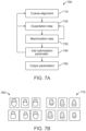
- FIG. 7A shows an example of a process of matching tooth and arch models to the edges.
- missing or broken teeth may be inserted into the parameterized 3D tooth and arch model.
- the parameterized model of that tooth may be replaced with a mean tooth model, thereby simulating a prosthetic tooth, such as a veneer, crown, or implant prosthetic.
- the missing tooth may be left as a space in the arch.
- a broken tooth may be left, as is, without replacing it with a mean shape tooth.
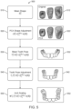
- FIG. 7A depicts a method 700 of building a patient-specific parametric model of a patient's teeth according to some embodiments.
- the method 700 may dynamically generate the parametric tooth models with lip and gingiva edges for matching with the teeth in the 2D image and block 710.
- the lip and gingiva edges maybe applied and/or dynamically adjusted at any of blocks 720, 730, and 740.
- the 3D tooth models may be computed on the fly for varying lip and gingiva line placement. Using such models provides for a much more accurate parametric model than using gingiva lines alone.
- the figure depicts examples of tooth models with gingiva edges 760 and tooth models with lip edges 770.
- the location of the gingiva and/or lip edges may be modified to adjust the fit of the silhouette of the tooth with the visible portion of a corresponding tooth in the 2D image.
- an expectation step is performed.
- an Expectation Management (EM) engine and/or an engine configured to create a 3D model performs block 720.
- EM Expectation Management
- a silhouette of the tooth is projected onto the 2D image and the edges of the silhouette are evaluated against the edges of the tooth in the 2D image as determined based on the lip, gingiva, and tooth edges.
- the evaluation may be a determination of the normal at a location at the edge of the silhouette and the closest location in the 2D image with a similar normal. Then the probability that the two edges are the same is determined. This process may be repeated for each location at the edge of the silhouette.
- a maximization step of the EM engine is performed.
- a small angle approximation is used in order to provide for an analytical solution to the maximization.
- the small angle approximation and analytical solution provides a much improved solution as compared to other methods, such as the Gaussian-Newton iterative method.
- the small angle approximation significantly reduces computation time and resolves to an accurate solution much faster.
- Blocks 720 and 730 may be performed iteratively on a single parameter or subset of parameters, performing the expectation step then the maximization step, then back to the expectation step and so on until a threshold of convergence for the single parameter or subset of parameters is reached. Then the process may proceed to block 740.
- an optimization parameter or subset of parameters are added to the parametric model.
- optimization of the parametric model may begin with ⁇ and T, then after iterating through the EM blocks 720 and 730, additional parameters are added.
- T ⁇ may be added and then optimized through the EM blocks 720 and 730 for additional iterations.
- the number of iterations before adding additional parameters may vary.
- the EM blocks 720 and 730 may be iterated through 3, 5, 7, 10, 15, 20, or an arbitrary number (e.g., any integer) of times.
- a ⁇ i may be added to the parametric model, which is processed though the EM blocks 720 and 730 until convergence is reached.
- outliers may be determined and filtered out.
- the process 700 may loop back to block 710, where a coarse alignment procession is performed based on the updated parametric model.
- FIG. 8 depicts a method 800 of rendering patient's teeth in an initial position, using a parametric model of the patient's arch, in accordance with one or more embodiments herein.
- the mean shape, S ⁇ C , of each tooth is determined.
- the mean shape may be based on the mean shape of a set of arches taken, e.g., from historical cases and/or those representing idealized arch forms, as discussed herein.
- the mean shape may be rendered, for example, on a screen for viewing by a patient or dental professional.
- the mean shape may be loaded into memory or retrieved from memory.
- the mean shape may also be initialized as a set of matrices, one for each tooth.
- a principal component analysis shape adjustment is performed on the mean shape of the teeth, S ⁇ C .
- the case specific coefficients for the principal components, a ⁇ i are applied to the principal component, B ⁇ i .
- the adjusted shape may be rendered, for example, on a screen for viewing by a patient or dental professional.
- adjusted tooth shapes are rendered for viewing.
- the adjusted shape may be stored into memory.
- the adjusted shape may also be stored as a set of matrices, one for each tooth.
- the mean tooth pose is determined.
- the mean tooth pose may be based on the mean tooth pose of a set of scanned arches, as discussed herein.
- each adjusted tooth is placed in its corresponding mean location and orientation, as determined by the mean arch.
- the mean tooth pose may be rendered, for example, on a screen for viewing by a patient or dental professional.
- the mean tooth pose may be loaded into memory or retrieved from memory.
- the mean tooth pose may also be initialized as a set of matrices and/or other data structures, e.g., one for each tooth in the tooth pose.
- the mean tooth shapes from block 810 may be placed in their corresponding mean tooth pose at block 830 before the shapes of the teeth are adjusted at block 820. In other words, the order of block 820 and block 830 may be swapped.
- a tooth pose adjustment is performed on the mean tooth pose.
- the pose adjustment T ⁇ is based on the particular tooth pose of a patient's arches, as discussed above.
- the position and orientation of each tooth is adjusted such that it is placed in a location and orientation as determined by the location and orientation of the teeth in patient's arch, or otherwise, as discussed herein.
- the adjusted tooth pose may be rendered, for example, on a screen for viewing by a patient or dental professional.
- the adjusted tooth pose may be stored in memory.
- the adjusted tooth pose may also be stored as a set of matrices and/or other data structures, e.g., one for each tooth in the tooth pose.
- the mean tooth shapes from block 810 may be placed in their corresponding adjusted tooth pose at block 840 before the shapes of the teeth are adjusted at block 820.
- the order of block 820 and blocks 830 and 840 may be swapped such that block 820 takes place after blocks 830 and 840.
- the arch is scaled such that it is generated with tooth dimensions according to the patient's tooth and arch size.
- an arch scaling factor ⁇ is based on the particular tooth and arch of a particular patient, as discussed above.
- the size of the arch is adjusted such that the scaled arch matches the size of a patient's arch, as determined, for example, by size of the teeth and arch in the patient's arch, or otherwise, as discussed herein.
- the scaled arch may be rendered, for example, on a screen for viewing by a patient or dental professional.
- the scaled arch may be stored in memory.
- the scaled arch may also be stored as a set of matrices and/or data structures, e.g., one for each tooth in the tooth pose.
- the mean tooth shapes from block 810 may be placed in their corresponding scaled position and size at block 850 before the shapes of the teeth are adjusted at block 820.
- the order of block 820 and blocks 830, 840, and 850 may be swapped such that block 820 takes place after blocks 830, 840, and 850.
- blocks 810 and 830 may be performed before blocks 820, 840, and 850.
- blocks 810, 820, 830, and 850 may be carried out before block 840.
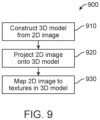
- FIG. 9 depicts a method 900 of constructing and applying textures to a 3D model, in accordance with one or more embodiments herein. Textures may aid in providing detail, such as color information, to the 3D model of a patient's teeth. As described herein, the process 900 uses images of the patient's teeth to provide lifelike textures for a patient's teeth.
- a 3D model of the patient's teeth and a 2D image of the patient are acquired, as described elsewhere herein, for example, in the discussion related to FIG. 5 .
- the 2D image and the 3D model should depict the teeth in the same positions, for example, the 3D model could be a parametric model derived from the 2D image of the patient.
- the 2D image of the patient's teeth is projected onto the 3D model and the image is aligned with the model.
- Such alignment may be carried out by matching contours in the 3D model with contours in the 2D image.
- Contours may include lip, gingiva, and teeth edges, determined as described elsewhere herein.
- FIG. 10A depicts a method 1000 for simulating an estimated and/or intended outcome of a dental treatment plan on a patient's teeth, in accordance with one or more embodiments herein.
- a model of a mean set of teeth arches is built.
- the model is a parametric 3D model of a mean arch based on a set of historic scanned arches and/or arches representing idealized arch forms.
- the scans are from the initial positions of patient's teeth.
- the scans are from patients after they have completed orthodontic treatment.
- the scans are taken without regard to whether the patient has undergone orthodontic treatment or not.
- the historic and/or idealized cases may represent arch models of treated patients (e.g., of patients who in the past have undergone treatment) and/or idealized arch models representing intended outcomes of various forms of orthodontic treatment.
- Block 1010 may include the process 350 as described with respect to FIG. 3B .
- cases are acquired. The cases may be retrieved from a datastore and may include previously scanned and segmented arch models.
- Simulated treatments or viewing customizations performed at block 1050 or block 1060 can be selected, de-selected, or adjusted by the user on the projected 2D image. Parameters can be adjusted to simulate treatments, such as whitening, gum line treatments, tooth replacement, or tooth repair, or for viewing customization, such as to display jaw open, closed, or partially open.
- the user can optionally adjust a color parameter to simulate tooth whitening.
- the user can adjust the color parameter to increase or decrease the degree of tooth whitening.
- the user can optionally adjust a gingiva line parameter to simulate gum line treatments or changes as a result of dental hygiene.
- a 2D image of a patient is captured, as described at block 1020 of FIG. 10A , and, at block 1025, the 3D model of the patient's teeth is constructed from the 2D image of the patient's teeth as at block 1030 of FIG. 10A .
- case-specific parameters are estimated as at block 1040 of FIG. 10A .
- the tooth shape parameters of the patient's teeth from the 3D model are used to perform a parameterized search of the treatment plan datastore.
- the shapes of the teeth in the patient's parameterized 3D model are compared to the parameterized shapes of the teeth in each of the historic records in the treatment datastore.
- the final tooth positions and orientations, or the final arch model of the match record may be used in the simulated treatment plan.
- a parameterized template arch may be identified based on comparison of tooth shape parameters to identify a matched template arch. In some embodiments, the match may be based on, for example, the closest match template arch.
- the template shape may be loaded into memory or retrieved from memory.
- the template shape may also be initialized as a set of matrices, one for each tooth. Once a match is found in a record within treatment datastore, the final arch model from the match record is retrieved and may be used as a basis for the patient's target final tooth positions.
- the tooth locations and orientations in the matched record are used as the basis for the tooth locations and orientations for the patient's target final tooth positions.
- the patient's parameterized arch model may be modified with the tooth locations and orientations in the matched record or the match record may be updated with the shape of the patient's teeth.
- the model of each of the patient's teeth with an unaltered tooth shape is placed in the final tooth pose determined from the matched record.
- the model of each of the patient's teeth with an adjusted shape, such as the teeth shapes from the matched record is placed in the final tooth pose determined from the matched record.
- a tooth pose adjustment can be performed to adjust the positions of the teeth in the final tooth pose.
- the final arch model from the matched record is used as the simulated final position for the patient's treatment in the 2D rendering.
- the teeth of the final arch model from the matched record are placed in positions according to the positions of the teeth in the patient's 2D photo.
- the teeth of the final arch model are placed in positions according to the positions of the teeth in the patient's parameterized 3D model.
- the final arch model optionally with positions adjusted according to the patient's 2D photo or 3D model, may be used as the simulated position in the 2D rendering.
- the shape of the template teeth may be adjusted based on the patient's parameterized 3D model to more closely match the patient's tooth shapes.
- a principal component analysis shape adjustment can be performed on the template teeth shape.
- the adjusted shape may be rendered, for example, on a screen for viewing by a user, patient, or dental professional.
- the adjusted shape may be stored into memory.
- the adjusted shape may also be stored as a set of matrices, one for each tooth.
- the patient's teeth are substituted for the teeth in the matching template from the treatment datastore.
- the template arch may be scaled such that it is generated with according to the patient's tooth and arch size.
- the template arch scaling factor ⁇ is based on the particular tooth and arch of a particular patient, as discussed above.
- the template arch scaling factor may also be based on one or more of the image size of the 2D image of the patient, for example, when scaling the 3D model for integration into a 2D image.
- the size of each template tooth and the template arch is adjusted such that the scaled template arch matches the size of a patient's arch as determined, for example, by the size of the teeth and arch in the patient's scanned arch, or otherwise, as discussed herein.
- the scaled template arch may be rendered, for example, on a screen for viewing by a user, patient, or dental professional.
- the scaled template arch may be stored in memory.
- the scaled template arch may also be stored as a set of matrices, one for each tooth in the tooth pose.
- the ideal template tooth shapes may be placed in their corresponding scaled position and size before the shapes of the teeth are adjusted.
- simulated treatments or viewing customizations such as gingiva line adjustment, jaw position, missing tooth insertion, or broken tooth repair, can be applied to the 3D model before rendering into 2D form. Simulated treatments or viewing customizations changes may be applied and adjusted as described at block 640.
- the 3D model is inserted into a 2D image of the patient.
- the 3D rendering of the teeth may be placed in the mouth of the patient as defined by the lip contours determined at block 1025 as part of the model construction process. Rendering may be performed with or without the simulated treatments or viewing customizations implemented at block 1045.
- inserting the 3D tooth model into the 2D image further comprises rendering an image of a parameterized gingiva line in the 2D image.
- the parameterized gingiva line may be determined, for example, as shown and described with respect to method 2001 of FIG. 20 .
- the textures model is adjusted to simulate clinical treatments. For example, color may be adjusted to simulate tooth whitening procedures.
- a mask can be generated from a 2D projection of the 3D tooth model.
- the mask can be applied to the 2D image of the patient's teeth, in either the initial or final positions.
- Color adjustment or whitening can be further applied to the mask region.
- Color adjustment and whitening parameters can be optionally selected and adjusted by the user.
- Simulated treatments and viewing customizations performed at block 1045 or block 1055 can be selected, de-selected, or adjusted by the user on the projected 2D image. Parameters can be adjusted to simulate treatment, such as whitening, gum line treatments, tooth replacement, or tooth repair, or for viewing customization, such as display jaw open, closed, or partially open.
- simulated treatment or viewing customizations Prior to rendering at block 1150 simulated treatment or viewing customizations, such as gingiva line adjustment, jaw position, missing tooth insertion, or broken tooth repair, can be applied to the 3D model. Simulated treatment or viewing customizations may be applied and adjusted as described at block 640. Simulated treatment or viewing customizations can be applied before or after arch scaling (e.g., before or after block 1140).
- the 3D model of the patient's teeth determined at block 1140 is rendered for viewing or the final 3D model is stored for later on-screen rendering.
- the 3D model can be rendered for viewing or stored for later on-screen rendering with or without the simulated treatment or viewing customizations.
- textures are applied to the 3D model of the patient's teeth in an estimated and/or intended final position. For example, textures determined based on a 2D image of the patient's teeth, for example, according to process 900 in FIG. 9 , may be applied to the 3D model. In some embodiments, the texture application process of block 1160 may occur during or as part of the rendering process of block 1150. Textures can be applied to a mask region, where the mask region may define a region corresponding to an oral feature, for example, lips, gingiva, or teeth. The mask region or a portion thereof may be determined, for example, by simulating the gingiva as shown and described with respect to method 2001 in FIG. 20 .
- textures model can be adjusted to simulate treatment or for customizable viewing.
- Simulated treatment or viewing customizations including color adjustments, e.g., to simulate tooth whitening, can be applied either to the 3D model or may occur as part of the rendering process.
- color adjustment can be performed at described at block 1060. Simulated treatment and viewing customizations, color adjustment can be adjusted by the user.
- step 1110 can be replaced by a parameterized search of the treatment plan datastore to identify a matched template model based on the patient's tooth shape.
- Steps 1120 through 1160 can subsequently be implemented as described using the template arch and tooth shape in place of the mean arch or tooth shape to determine ideal tooth pose instead of mean tooth pose.
- An initial determination of the edges of the oral features may be identified by a machine learning algorithm.
- Initial tooth contours are extracted from the image and may have a brightness or other scale applied to them.
- the initial contours may then undergo binerization to change the pixels of the image to a binary scale.
- the binarized tooth contours are thinned to, for example, a single pixel width, forming a thinned tooth contour.
- the initial determination of the patient's lips may be based on facial landmarks, such as the lip landmarks determined according to a machine learning algorithm, such as a convoluted neural network.
- the lip contours have a brightness or other scale applied to them.
- the lip contours are binarized, thinned, and contoured, as with the initial tooth contours.
- the binarized and thinned tooth and lip contours may define the edges of the oral features. The edges may be determined for example, as described above with respect to FIG. 6 .
- patient-specific input parameters for gingiva are determined.
- the input parameters may include the patient-specific input parameters shown in FIG. 21A .
- the patient-specific input parameters may be determined by the shape and scale of one or more of the oral features of the captured 2D image of the patient.
- the patient-specific input parameters may be determined based on the edges of the oral features, for example, as illustrated in 2100 of FIG. 21B .
- the edges of the oral features may include, for example, edges of lips 2110, edges teeth 2120, and edges of gingiva 2130, determined at block 2021.
- the patient-specific input parameters may include a patient tooth height, which may be a distance between an incisal edge 2120 of a tooth and the edge of the gingiva 2130 or gingiva line and may be determined for each tooth of a patient's arch.
- the patient tooth height may be denoted by h g , as shown, for example, in FIG. 21A .
- the patient tooth height may be a maximal distance between the incisal edge 2120 of the tooth and the edge of the gingiva 2130.
- the maximal distance may be measured as the distance between the incisal edge 2120 of the tooth and the edge of the gingiva 2130 at the gingival zenith.
- the patient-specific input parameters may include a gingival tip distance, which may be a distance between the edge of the lip 2110 and the gingiva line 2140. The distance may be determined at a position between each pair of neighboring teeth of the patient's arch.
- the gingival tip distance may be denoted by h b , as shown, for example, in FIG. 21A .
- the patient tooth height may be a maximal distance between the edge of the lip 2110 and the edge of the gingiva 2140. The maximal may be measured as the distance between the lip and the edge of the gingiva 2140 at the gingival nadir.
- the patient-specific input parameters may include a gingival height, which may be a distance between the edge of the lip 2110, and the gingiva line 2130, determined for each tooth of a patient's arch, the gingival height may be denoted by h t , as shown, for example, in FIG. 21A .
- the gingival height may be a minimal distance between the edge of the lip 2110 and the gingival zenith 2130.
- the patient-specific input parameters may include a tooth width, determined for each tooth of the patient's arch.
- the tooth width may be denoted by w, as shown, for example, in FIG. 21A .
- the tooth width may be a width of a tooth at the incisal edge 2120.
- the tooth width may be a width of a tooth at the maximal tooth width.
- simulated parameters for gingiva are determined.
- the simulated parameters may be derived based on the patient-specific input parameters and may be used in generating the simulated gingiva.
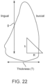
- the parameters of gingiva tip parameter, denoted by h , visible tooth height, denoted by g , and tooth curvature, denoted by R may be a convolution of patient-specific input parameters, as shown in FIG. 22 .
- they may be a convolution of patient-specific parameters and simulated input parameters or ideal aesthetic parameters.
- An 'ideal tooth,' may include a representation of a tooth or parameters of a taken from a model arch, such as those of historical cases and/or those representing idealized arch forms.
- the simulated input parameters or ideal aesthetic parameters may be, for example, the parameters of ideal tooth height, denoted by H g , customizable tooth height scaling parameters denoted by c 1 and c 2 , a customizable gingiva tip scaling parameter, denoted by s , and a tooth shape scaling parameter, denoted by m.
- the visible tooth height, denoted by g may be a weighted average of the visible tooth height of a patient's teeth determined based on the 2D image, denoted by h g , and an ideal tooth height, denoted by H g .
- c 1 may be 0.1, 0.2, 0.3, 0.4, 0.5, 0.6, 0.7, 0.8, or 0.9.
- c 1 may be from 0.1 to 0.5, 0.2 to 0.6, 0.3 to 0.7, 0.4 to 0.8, or 0.5 to 0.9.
- c 1 is adjusted by a user, such as a dental professional or patient.
- s may be adjusted based on the difference of ideal tooth length H g and the patient's tooth length h g .
- s may be 0.8, 0.9, 1.0, 1.1, 1.2, 1.3, 1.4, 1.5, 1.6, 1.7, 1.8, 1.9, or 2.0.
- s may be varied from 0.8 to 1.0, 0.9 to 1.1, 1.0 to 1.2, 1.1 to 1.3, 1.2 to 1.4, 1.3 to 1.5, 1.4 to 1.6, 1.5 to 1.7, 1.6 to 1.8, 1.7 to 1.9, 1.8 to 2.0, or 0.8 to 2.0.
- s is adjusted by a user, such as a dental professional or patient.
- a maximum threshold for the gingiva tip parameter, denoted by h , for each tooth may be set as a fraction of patient tooth height, denoted by h g .
- the gingiva tip parameter, h may be set so as not to exceed 0.2 h g , 0.3 h g , 0.4 h g , 0.5 h g , 0.6 h g , 0.7 h g , 0.75 h g , 0.8 h g , 0.85 h g , or 0.9 h g .
- the maximum threshold for the gingiva tip parameter, h may be set as a fraction of visible tooth height, denoted by g .
- h may not exceed 0.2 g, 0.3 g, 0.4 g, 0.5 g, 0.6 g, 0.7 g, 0.75 g, 0.8 g, 0.85 g , or 0.9 g.
- the tooth curvature parameter, denoted by R may be a function of the patient-specific gingiva width parameter, denoted by h t , tooth thickness, denoted by T, and a tooth shape scaling parameter, denoted by m.
- the tooth thickness, denoted by T may be determined based on the parameterized 3D model of the patient's teeth, for example, where T is the distance between a lingual surface and a buccal surface of a tooth at the midpoint of the gingiva line.
- m is adjusted based on the patient's tooth length, denoted by h g .
- parameterized 3D teeth and arch models are matched to each of the patient's teeth that are depicted in the 2D image of the patient.
- the matching is based on the contours, determined above.
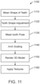
- the treatment plan simulation engine 1356 retrieves or otherwise determines the mean shape, S ⁇ C .
- the mean shape may be retrieved from scanned tooth normalization engine 1354.
- the mean shape may be loaded into memory or retrieved from memory.
- the mean shape may also be initialized as a set of matrices, one for each tooth.
- the treatment plan remodeling engine 1356 uses the tooth position and orientation coordinates from the ideal parameterized datastore match and applies the shape and textures of the patient's 3D model generated from the 2D image to the tooth positions and orientations to generate an arch.
- the treatment plan simulation engine 1356 scales the arch such that it is generated according to the patient's tooth and arch size.
- the arch scaling factor ⁇ is based on the particular tooth and arch of a particular patient, as discussed above.
- the arch is adjusted such that the scaled arch matches the size of a patient's arch, as determined, for example, by size of the teeth and arch in the patient's scanned arch, or otherwise, as discussed herein.
- the scaled arch may be rendered, for example, on a screen for viewing by a patient or dental professional.
- the scaled arch may be stored in memory.
- the scaled arch may also be stored as a set of matrices, one for each tooth in the tooth pose.
- the scaled arch may be sent to the treatment rendering engine 1330.
- the treatment rendering engine 1330 renders the teeth and 2D image of the patient in a final position, as determined, for example, by the parametric treatment prediction engine 1350 and, in particular, the treatment plan simulation engine 1356 therein.
- the treatment rendering engine 1330 may carry out some of the processes described with reference to FIGS. 9 , 10 , and 11 . In particular, the rendering processes descried with reference to FIGS. 9 , 10 , 11 , and elsewhere herein.
- FIG. 14 illustrates an exemplary tooth repositioning appliance or aligner 1500 that can be worn by a patient in order to achieve an incremental repositioning of individual teeth 1502 in the jaw.
- the appliance can include a shell (e.g., a continuous polymeric shell or a segmented shell) having teeth-receiving cavities that receive and resiliently reposition the teeth.
- An appliance or portion(s) thereof may be indirectly fabricated using a physical model of teeth.
- an appliance e.g., polymeric appliance
- the physical model (e.g., physical mold) of teeth can be formed through a variety of techniques, including 3D printing.
- the appliance can be formed by thermoforming the appliance over the physical model.
- a physical appliance is directly fabricated, e.g., using additive manufacturing techniques, from a digital model of an appliance.
- the physical appliance may be created through a variety of direct formation techniques, such as 3D printing.
- An appliance can fit over all teeth present in an upper or lower jaw, or less than all of the teeth.
- the appliance can be designed specifically to accommodate the teeth of the patient (e.g., the topography of the tooth-receiving cavities matches the topography of the patient's teeth), and may be fabricated based on positive or negative models of the patient's teeth generated by impression, scanning, and the like.
- the appliance can be a generic appliance configured to receive the teeth, but not necessarily shaped to match the topography of the patient's teeth.
- the appliance can be a generic appliance configured to receive the teeth, but not necessarily shaped to match the topography of the patient's teeth.
- only certain teeth received by an appliance will be repositioned by the appliance while other teeth can provide a base or anchor region for holding the appliance in place as it applies force against the tooth or teeth targeted for repositioning.
- some or most, and even all, of the teeth will be repositioned at some point during treatment. Teeth that are moved can also serve as a base or anchor for holding the appliance as it is worn by the patient.
- no wires or other means will be provided for holding an appliance in place over the teeth.
- auxiliary components e.g., features, accessories, structures, devices, components, and the like
- auxiliary components include but are not limited to elastics, wires, springs, bars, arch expanders, palatal expanders, twin blocks, occlusal blocks, bite ramps, mandibular advancement splints, bite plates, pontics, hooks, brackets, headgear tubes, springs, bumper tubes, palatal bars, frameworks, pin-and-tube apparatuses, buccal shields, buccinator bows, wire shields, lingual flanges and pads, lip pads or bumpers, protrusions, divots, and the like.
- the appliances, systems and methods described herein include improved orthodontic appliances with integrally formed features that are shaped to couple to such auxiliary components, or that replace such auxiliary components.
- FIG. 15 illustrates a tooth repositioning system 1510 including a plurality of appliances 1512, 1514, 1516.
- Any of the appliances described herein can be designed and/or provided as part of a set of a plurality of appliances used in a tooth repositioning system.
- Each appliance may be configured so a tooth-receiving cavity has a geometry corresponding to an intermediate or final tooth arrangement intended for the appliance.
- the patient's teeth can be progressively repositioned from an initial tooth arrangement towards a target tooth arrangement by placing a series of incremental position adjustment appliances over the patient's teeth.
- the tooth repositioning system 1510 can include a first appliance 1512 corresponding to an initial tooth arrangement, one or more intermediate appliances 1514 corresponding to one or more intermediate arrangements, and a final appliance 1516 corresponding to a target arrangement.
- a target tooth arrangement can be a planned final tooth arrangement selected for the patient's teeth at the end of all planned orthodontic treatment.
- a target arrangement can be one of some intermediate arrangements for the patient's teeth during the course of orthodontic treatment, which may include various different treatment scenarios, including, but not limited to, instances where surgery is recommended, where interproximal reduction (IPR) is appropriate, where a progress check is scheduled, where anchor placement is best, where palatal expansion is desirable, where restorative dentistry is involved (e.g., inlays, onlays, crowns, bridges, implants, veneers, and the like), etc.
- IPR interproximal reduction
- a target tooth arrangement can be any planned resulting arrangement for the patient's teeth that follows one or more incremental repositioning stages.
- an initial tooth arrangement can be any initial arrangement for the patient's teeth that is followed by one or more incremental repositioning stages.
- the appliances are generally not affixed to the teeth and the patient may place and replace the appliances at any time during the procedure (e.g., patient-removable appliances).
- the final appliance or several appliances in the series may have a geometry or geometries selected to overcorrect the tooth arrangement. For instance, one or more appliances may have a geometry that would (if fully achieved) move individual teeth beyond the tooth arrangement that has been selected as the "final.” Such over-correction may be desirable in order to offset potential relapse after the repositioning method has been terminated (e.g., permit movement of individual teeth back toward their pre-corrected positions).
- Over-correction may also be beneficial to speed the rate of correction (e.g., an appliance with a geometry that is positioned beyond a desired intermediate or final position may shift the individual teeth toward the position at a greater rate). In such cases, the use of an appliance can be terminated before the teeth reach the positions defined by the appliance. Furthermore, over-correction may be deliberately applied in order to compensate for any inaccuracies or limitations of the appliance.
- the various embodiments of the orthodontic appliances presented herein can be fabricated in a wide variety of ways.
- the orthodontic appliances herein (or portions thereof) can be produced using direct fabrication, such as additive manufacturing techniques (also referred to herein as "3D printing) or subtractive manufacturing techniques (e.g., milling).
- direct fabrication involves forming an object (e.g., an orthodontic appliance or a portion thereof) without using a physical template (e.g., mold, mask etc.) to define the object geometry.
- the orthodontic appliances herein can be fabricated using a combination of direct and indirect fabrication techniques, such that different portions of an appliance can be fabricated using different fabrication techniques and assembled in order to form the final appliance.
- an appliance shell can be formed by indirect fabrication (e.g., thermoforming), and one or more structures or components as described herein (e.g., auxiliary components, power arms, etc.) can be added to the shell by direct fabrication (e.g., printing onto the shell).
- the configuration of the orthodontic appliances herein can be determined according to a treatment plan for a patient, e.g., a treatment plan involving successive administration of a plurality of appliances for incrementally repositioning teeth.
- Computer-based treatment planning and/or appliance manufacturing methods can be used in order to facilitate the design and fabrication of appliances.
- one or more of the appliance components described herein can be digitally designed and fabricated with the aid of computer-controlled manufacturing devices (e.g., computer numerical control (CNC) milling, computer-controlled additive manufacturing such as 3D printing, etc.).
- CNC computer numerical control
- additive manufacturing such as 3D printing, etc.
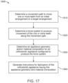
- FIG. 17 illustrates a method 1800 for designing an orthodontic appliance to be fabricated, in accordance with embodiments.
- the method 1800 can be applied to any embodiment of the orthodontic appliances described herein.
- Some or all of the operations of the method 200 can be performed by any suitable data processing system or device, e.g., one or more processors configured with suitable instructions.
- a movement path to move one or more teeth from an initial arrangement to a target arrangement is determined.
- the initial arrangement can be determined from a mold or a scan of the patient's teeth or mouth tissue, e.g., using wax bites, direct contact scanning, x-ray imaging, tomographic imaging, sonographic imaging, and other techniques for obtaining information about the position and structure of the teeth, jaws, gums and other orthodontically relevant tissue.
- a digital data set can be derived that represents the initial (e.g., pretreatment) arrangement of the patient's teeth and other tissues.
- the initial digital data set is processed to segment the tissue constituents from each other. For example, data structures that digitally represent individual tooth crowns can be produced.
- digital models of entire teeth can be produced, including measured or extrapolated hidden surfaces and root structures, as well as surrounding bone and soft tissue.
- the target arrangement of the teeth (e.g., a desired and intended end result of orthodontic treatment) can be received from a clinician in the form of a prescription, can be calculated from basic orthodontic principles, and/or can be extrapolated computationally from a clinical prescription.
- the final position and surface geometry of each tooth can be specified to form a complete model of the tooth arrangement at the desired end of treatment.
- a movement path can be defined for the motion of each tooth.
- the movement paths are configured to move the teeth in the quickest fashion with the least amount of round-tripping to bring the teeth from their initial positions to their desired target positions.
- the tooth paths can optionally be segmented, and the segments can be calculated so that each tooth's motion within a segment stays within threshold limits of linear and rotational translation.
- the end points of each path segment can constitute a clinically viable repositioning, and the aggregate of segment end points can constitute a clinically viable sequence of tooth positions, so that moving from one point to the next in the sequence does not result in a collision of teeth.
- a force system to produce movement of the one or more teeth along the movement path is determined.
- a force system can include one or more forces and/or one or more torques. Different force systems can result in different types of tooth movement, such as tipping, translation, rotation, extrusion, intrusion, root movement, etc.
- Biomechanical principles, modeling techniques, force calculation/measurement techniques, and the like, including knowledge and approaches commonly used in orthodontia, may be used to determine the appropriate force system to be applied to the tooth to accomplish the tooth movement.
- sources may be considered including literature, force systems determined by experimentation or virtual modeling, computer-based modeling, clinical experience, minimization of unwanted forces, etc.
- Determination of the force system can be performed in a variety of ways. For example, in some embodiments, the force system is determined on a patient-by-patient basis, e.g., using patient-specific data. Alternatively or in combination, the force system can be determined based on a generalized model of tooth movement (e.g., based on experimentation, modeling, clinical data, etc.), such that patient-specific data is not necessarily used. In some embodiments, determination of a force system involves calculating specific force values to be applied to one or more teeth to produce a particular movement. Alternatively, determination of a force system can be performed at a high level without calculating specific force values for the teeth.
- block 1820 can involve determining a particular type of force to be applied (e.g., extrusive force, intrusive force, translational force, rotational force, tipping force, torqueing force, etc.) without calculating the specific magnitude and/or direction of the force.
- a particular type of force to be applied e.g., extrusive force, intrusive force, translational force, rotational force, tipping force, torqueing force, etc.
- an appliance geometry and/or material composition for an orthodontic appliance configured to produce the force system is determined.
- the appliance can be any embodiment of the appliances discussed herein, such as an appliance having variable localized properties, integrally formed components, and/or power arms.
- the appliance comprises a heterogeneous thickness, a heterogeneous stiffness, or a heterogeneous material composition.
- the appliance comprises two or more of a heterogeneous thickness, a heterogeneous stiffness, or a heterogeneous material composition.
- the appliance comprises a heterogeneous thickness, a heterogeneous stiffness, and a heterogeneous material composition.
- the heterogeneous thickness, stiffness, and/or material composition can be configured to produce the force system for moving the teeth, e.g., by preferentially applying forces at certain locations on the teeth.
- an appliance with heterogeneous thickness can include thicker portions that apply more force on the teeth than thinner portions.
- an appliance with heterogeneous stiffness can include stiffer portions that apply more force on the teeth than more elastic portions. Variations in stiffness can be achieved by varying the appliance thickness, material composition, and/or degree of photopolymerization, as described herein.
- determining the appliance geometry and/or material composition comprises determining the geometry and/or material composition of one or more integrally formed components to be directly fabricated with an appliance shell.
- the integrally formed component can be any of the embodiments described herein.
- the geometry and/or material composition of the integrally formed component(s) can be selected to facilitate application of the force system onto the patient's teeth.
- the material composition of the integrally formed component can be the same as or different from the material composition of the shell.
- determining the appliance geometry comprises determining the geometry for a variable gable bend.
- the block 1830 can involve analyzing the desired force system in order to determine an appliance geometry and material composition that would produce the force system.
- the analysis involves determining appliance properties (e.g., stiffness) at one or more locations that would produce a desired force at the one or more locations.
- the analysis can then involve determining an appliance geometry and material composition at the one or more locations to achieve the specified properties. Determination of the appliance geometry and material composition can be performed using a treatment or force application simulation environment.
- a simulation environment can include, e.g., computer modeling systems, biomechanical systems or apparatus, and the like.
- digital models of the appliance and/or teeth can be produced, such as finite element models.
- the finite element models can be created using computer program application software available from a variety of vendors.
- CAE computer aided engineering
- CAD computer aided design
- program products from a number of vendors can be used, including finite element analysis packages from ANSYS, Inc., of Canonsburg, PA, and SIMULIA(Abaqus) software products from Dassault Systèmes of Waltham, MA.
- one or more appliance geometries and material compositions can be selected for testing or force modeling.
- a desired tooth movement as well as a force system required or desired for eliciting the desired tooth movement, can be identified.
- a candidate appliance geometry and composition can be analyzed or modeled for determination of an actual force system resulting from use of the candidate appliance.
- One or more modifications can optionally be made to a candidate appliance, and force modeling can be further analyzed as described, e.g., in order to iteratively determine an appliance design that produces the desired force system.
- block 1830 can further involve determining the geometry of one or more auxiliary components to be used in combination with the orthodontic appliance in order to exert the force system on the one or more teeth.
- auxiliaries can include one or more of tooth-mounted attachments, elastics, wires, springs, bite blocks, arch expanders, wire-and-bracket appliances, shell appliances, headgear, or any other orthodontic device or system that can be used in conjunction with the orthodontic appliances herein.
- the use of such auxiliary components may be advantageous in situations where it is difficult for the appliance alone to produce the force system.
- auxiliary components can be added to the orthodontic appliance in order to provide other desired functionalities besides producing the force system, such as mandibular advancement splints to treat sleep apnea, pontics to improve aesthetic appearance, and so on.
- the auxiliary components are fabricated and provided separately from the orthodontic appliance.
- the geometry of the orthodontic appliance can be modified to include one or more auxiliary components as integrally formed components.
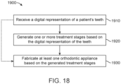
- a digital representation of a patient's teeth is received.
- the digital representation can include surface topography data for the patient's intraoral cavity (including teeth, gingival tissues, etc.).
- the surface topography data can be generated by directly scanning the intraoral cavity, a physical model (positive or negative) of the intraoral cavity, or an impression of the intraoral cavity, using a suitable scanning device (e.g., a handheld scanner, desktop scanner, etc.).
- the methods herein can accommodate production and immediate delivery of the entire series of appliances on site during a single visit.
- Chair side manufacturing can thus improve the convenience and speed of the treatment procedure by allowing the patient to immediately begin treatment at the practitioner's office, rather than having to wait for fabrication and delivery of the appliances at a later date.
- chair side manufacturing can provide improved flexibility and efficiency of orthodontic treatment. For instance, in some embodiments, the patient is re-scanned at each appointment to determine the actual positions of the teeth, and the treatment plan is updated accordingly. Subsequently, new appliances can be immediately produced and delivered chair side to accommodate any changes to or deviations from the treatment plan.
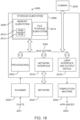
- the user interface input devices 2018 are not limited to any particular device, and can typically include, for example, a keyboard, pointing device, mouse, scanner, interactive displays, touchpad, joysticks, etc.
- various user interface output devices can be employed in a system of the invention, and can include, for example, one or more of a printer, display (e.g., visual, non-visual) system/subsystem, controller, projection device, audio output, and the like.
- Storage subsystem 2006 maintains the basic required programming, including computer readable media having instructions (e.g., operating instructions, etc.), and data constructs.
- the program modules discussed herein are typically stored in storage subsystem 2006.
- Storage subsystem 2006 typically includes memory subsystem 2008 and file storage subsystem 2014.
- Memory subsystem 2008 typically includes a number of memories (e.g., RAM 2010, ROM 2012, etc.) including computer readable memory for storage of fixed instructions, instructions and data during program execution, basic input/output system, etc.
- File storage subsystem 2014 provides persistent (non-volatile) storage for program and data files, and can include one or more removable or fixed drives or media, hard disk, floppy disk, CD-ROM, DVD, optical drives, and the like.
- One or more of the storage systems, drives, etc. may be located at a remote location, such coupled via a server on a network or via the internet/World Wide Web.
- bus subsystem is used generically so as to include any mechanism for letting the various components and subsystems communicate with each other as intended and can include a variety of suitable components/systems that would be known or recognized as suitable for use therein. It will be recognized that various components of the system can be, but need not necessarily be at the same physical location, but could be connected via various local-area or wide-area network media, transmission systems, etc.
- Scanner 2020 includes any means for obtaining a digital representation (e.g., images, surface topography data, etc.) of a patient's teeth (e.g., by scanning physical models of the teeth such as casts 2027, by scanning impressions taken of the teeth, or by directly scanning the intraoral cavity), which can be obtained either from the patient or from treating professional, such as an orthodontist, and includes means of providing the digital representation to data processing system 2000 for further processing.
- Scanner 2020 may be located at a location remote with respect to other components of the system and can communicate image data and/or information to data processing system 2000, for example, via a network interface 2024. Fabrication machine 2022 fabricates appliances 2023 based on a treatment plan, including data set information received from data processing system 2000.
- Fabrication machine 2022 can, for example, be located at a remote location and receive data set information from data processing system 2000 via network interface 2024.
- the camera 2025 may include any image capture device configured to capture still images or movies.
- the camera 2025 may facilitate capturing various perspectives of a patient's dentition.
- the camera 2025 may facilitate capture of images at various focal lengths and distances from the patient.
- Data processing aspects of the methods described herein can be implemented in digital electronic circuitry, or in computer hardware, firmware, software, or suitable combinations thereof.
- Data processing apparatus can be implemented in a computer program product tangibly embodied in a machine-readable storage device for execution by a programmable processor.
- Data processing blocks can be performed by a programmable processor executing program instructions to perform functions by operating on input data and generating output.
- the data processing aspects can be implemented in one or more computer programs that are executable on a programmable system, the system including one or more programmable processors operably coupled to a data storage system.
- a processor will receive instructions and data from a read-only memory and/or a random access memory.
- Storage devices suitable for tangibly embodying computer program instructions and data include all forms of nonvolatile memory, such as: semiconductor memory devices, such as EPROM, EEPROM, and flash memory devices; magnetic disks such as internal hard disks and removable disks; magneto-optical disks; and CD-ROM disks.
- semiconductor memory devices such as EPROM, EEPROM, and flash memory devices
- magnetic disks such as internal hard disks and removable disks
- magneto-optical disks such as CD-ROM disks.
- a “dental positioning appliance” or an “orthodontic appliance” may be treated synonymously, and may include any dental appliance configured to change the position of a patient's teeth in accordance with a plan, such as an orthodontic treatment plan.
- a "patient,” as used herein may include any person, including a person seeking dental/orthodontic treatment, a person undergoing dental/orthodontic treatment, and a person who has previously undergone dental/orthodontic treatment.
- a “patient” may include a customer or a prospective customer of orthodontic treatment, such as a person who is using the visualization tools herein to inform a decision to undergo orthodontic treatment at all or a decision to select a specific orthodontic treatment plan.
- a “dental positioning appliance” or “orthodontic appliance,” as used herein, may include a set of dental appliances configured to incrementally change the position of a patient's teeth over time.
- dental positioning appliances and/or orthodontic appliances may comprise polymeric appliances configured to move a patient's teeth in accordance with an orthodontic treatment plan.
- the term "and/or” may be used as a functional word to indicate that two words or expressions are to be taken together or individually.
- the phrase “A and/or B” encompasses A alone, B alone, and A and B together.
- the term “or” need not exclude one of a plurality of words/expressions.
- the phrase “A or B” need not exclude A and B together.
- a “moment” may encompass a force acting on an object such as a tooth at a distance from a center of resistance.
- the moment may be calculated with a vector cross product of a vector force applied to a location corresponding to a displacement vector from the center of resistance, for example.
- the moment may comprise a vector pointing in a direction.
- a moment opposing another moment may encompass one of the moment vectors oriented toward a first side of the object such as the tooth and the other moment vector oriented toward an opposite side of the object such as tooth, for example. Any discussion herein referring to application of forces on a patient's teeth is equally applicable to application of moments on the teeth, and vice-versa.
- a "plurality of teeth” may encompass two or more teeth.
- a plurality of teeth may, but need not, comprise adjacent teeth.
- one or more posterior teeth comprises one or more of a molar, a premolar, or a canine, and one or more anterior teeth comprising one or more of a central incisor, a lateral incisor, a cuspid, a first bicuspid, or a second bicuspid.
- the embodiments disclosed herein may be well suited for moving one or more teeth of the first group of one or more teeth or moving one or more of the second group of one or more teeth, and combinations thereof.
- the embodiments disclosed herein may be well suited for combination with one or more commercially available tooth moving components such as attachments and polymeric shell appliances.
- the appliance and one or more attachments are configured to move one or more teeth along a tooth movement vector comprising six degrees of freedom, in which three degrees of freedom are rotational and three degrees of freedom are translation.
- Repositioning of teeth may be accomplished with the use of a series of removable elastic positioning appliances such as the Invisalign ® system available from Align Technology, Inc., the assignee of the present disclosure.
- Such appliances may have a thin shell of elastic material that generally conforms to a patient's teeth but is slightly out of alignment with an initial or immediately prior tooth configuration. Placement of the appliance over the teeth applies controlled forces in specific locations to gradually move the teeth into the new configuration. Repetition of this process with successive appliances comprising new configurations eventually moves the teeth through a series of intermediate configurations or alignment patterns to a final desired configuration.
- Repositioning of teeth may be accomplished through other series of removable orthodontic and/or dental appliances, including polymeric shell appliances.
- a computer system is intended to be construed broadly.
- a computer system will include a processor, memory, non-volatile storage, and an interface.
- a typical computer system will usually include at least a processor, memory, and a device (e.g., a bus) coupling the memory to the processor.
- the processor can be, for example, a general-purpose central processing unit (CPU), such as a microprocessor, or a special-purpose processor, such as a microcontroller.
- the memory can include, by way of example but not limitation, random access memory (RAM), such as dynamic RAM (DRAM) and static RAM (SRAM).
- RAM random access memory
- DRAM dynamic RAM
- SRAM static RAM
- the memory can be local, remote, or distributed.
- the bus can also couple the processor to non-volatile storage.
- the non-volatile storage is often a magnetic floppy or hard disk, a magnetic-optical disk, an optical disk, a read-only memory (ROM), such as a CD-ROM, EPROM, or EEPROM, a magnetic or optical card, or another form of storage for large amounts of data. Some of this data is often written, by a direct memory access process, into memory during execution of software on the computer system.
- the non-volatile storage can be local, remote, or distributed.
- the non-volatile storage is optional because systems can be created with all applicable data available in memory.
- Software is typically stored in the non-volatile storage. Indeed, for large programs, it may not even be possible to store the entire program in the memory. Nevertheless, it should be understood that for software to run, if necessary, it is moved to a computer-readable location appropriate for processing, and for illustrative purposes, that location is referred to as the memory in this paper. Even when software is moved to the memory for execution, the processor will typically make use of hardware registers to store values associated with the software, and local cache that, ideally, serves to speed up execution.
- a software program is assumed to be stored at an applicable known or convenient location (from non-volatile storage to hardware registers) when the software program is referred to as "implemented in a computer-readable storage medium.”
- a processor is considered to be “configured to execute a program” when at least one value associated with the program is stored in a register readable by the processor.
- a computer system can be controlled by operating system software, which is a software program that includes a file management system, such as a disk operating system.
- operating system software is a software program that includes a file management system, such as a disk operating system.
- file management system is typically stored in the non-volatile storage and causes the processor to execute the various acts required by the operating system to input and output data and to store data in the memory, including storing files on the non-volatile storage.
- the bus can also couple the processor to the interface.
- the interface can include one or more input and/or output (I/O) devices.
- the I/O devices can include, by way of example but not limitation, a keyboard, a mouse or other pointing device, disk drives, printers, a scanner, and other I/O devices, including a display device.
- the display device can include, by way of example but not limitation, a cathode ray tube (CRT), liquid crystal display (LCD), or some other applicable known or convenient display device.
- the interface can include one or more of a modem or network interface. It will be appreciated that a modem or network interface can be considered to be part of the computer system.
- the interface can include an analog modem, ISDN modem, cable modem, token ring interface, satellite transmission interface (e.g. "direct PC"), or other interfaces for coupling a computer system to other computer systems. Interfaces enable computer systems and other devices to be coupled together in a network.
- the computer systems can be compatible with or implemented as part of or through a cloud-based computing system.
- a cloud-based computing system is a system that provides virtualized computing resources, software and/or information to end user devices.
- the computing resources, software and/or information can be virtualized by maintaining centralized services and resources that the edge devices can access over a communication interface, such as a network.
- "Cloud” may be a marketing term and for the purposes of this paper can include any of the networks described herein.
- the cloud-based computing system can involve a subscription for services or use a utility pricing model. Users can access the protocols of the cloud-based computing system through a web browser or other container application located on their end user device.
- datastores are intended to include repositories having any applicable organization of data, including tables, comma-separated values (CSV) files, traditional databases (e.g., SQL), or other applicable known or convenient organizational formats.
- Datastores can be implemented, for example, as software embodied in a physical computer-readable medium on a specific-purpose machine, in firmware, in hardware, in a combination thereof, or in an applicable known or convenient device or system.
- Datastore-associated components such as database interfaces, can be considered "part of" a datastore, part of some other system component, or a combination thereof, though the physical location and other characteristics of datastore-associated components is not critical for an understanding of the techniques described in this paper.
Landscapes
- Health & Medical Sciences (AREA)
- Engineering & Computer Science (AREA)
- Life Sciences & Earth Sciences (AREA)
- General Health & Medical Sciences (AREA)
- Animal Behavior & Ethology (AREA)
- Public Health (AREA)
- Veterinary Medicine (AREA)
- Oral & Maxillofacial Surgery (AREA)
- Dentistry (AREA)
- Epidemiology (AREA)
- Physics & Mathematics (AREA)
- General Engineering & Computer Science (AREA)
- Medical Informatics (AREA)
- Surgery (AREA)
- Nuclear Medicine, Radiotherapy & Molecular Imaging (AREA)
- Theoretical Computer Science (AREA)
- General Physics & Mathematics (AREA)
- Heart & Thoracic Surgery (AREA)
- Quality & Reliability (AREA)
- Computer Hardware Design (AREA)
- Robotics (AREA)
- Computer Graphics (AREA)
- Biomedical Technology (AREA)
- Architecture (AREA)
- Molecular Biology (AREA)
- Software Systems (AREA)
- Radiology & Medical Imaging (AREA)
- Computer Vision & Pattern Recognition (AREA)
- Optics & Photonics (AREA)
- Dental Tools And Instruments Or Auxiliary Dental Instruments (AREA)
- Apparatus For Radiation Diagnosis (AREA)
- Instructional Devices (AREA)
Claims (9)
- Computerimplementiertes Verfahren (2001) zur Wiedergabe des Zahnfleischs eines Patienten, wobei das computerimplementierte Verfahren (2001) umfasst:Erfassen (2011) eines ersten 2D-Bilds des Gesichts eines Patienten, einschließlich der Zähne und des Zahnfleischs;Erstellen eines parametrischen Modells des Zahnfleischs des Patienten auf der Grundlage des ersten 2D-Bilds, wobei das parametrische Modell patientenspezifische Eingabeparameter für das Zahnfleisch des Patienten umfasst, durch:Finden (2021) von Kanten von Zähnen (2120), Zahnfleisch (2130) und Lippen (2110) in dem ersten 2D-Bild; undBestimmen (2031) der patientenspezifischen Eingabeparameter aus den Kanten der Zähne (2120), den Lippen (2110) und dem Zahnfleisch (2130);Angleichen (2041) von Koordinaten von patientenspezifischen Eingabeparametern aus dem parametrischen Modell des Zahnfleischs des Patienten; undWiedergeben (2061) eines zweiten 2D-Bilds des Gesichts des Patienten mit Zähnen und Zahnfleisch auf der Grundlage der angeglichenen Koordinaten des Zahnfleischs des Patienten.
- Computerimplementiertes Verfahren nach Anspruch 1, wobei Erstellen des parametrischen Modells des Zahnfleischs des Patienten ferner Modifizieren der patientenspezifischen Eingabeparameter auf der Grundlage von simulierten Eingabeparametern umfasst, wobei einer oder mehrere der simulierten Eingabeparameter auf der Grundlage des parametrischen Modells der Zähne des Patienten stehen.
- Computerimplementiertes Verfahren nach Anspruch 2, wobei die simulierten Eingabeparameter eines oder mehrere umfassen von: einem Zahnfleischspitzenparameter, einer idealen Zahnhöhe, einer Zahndicke, einem Abstand von einer Zahnfleischlinie zu einer Lippe und einer sichtbaren Zahnhöhe.
- Computerimplementiertes Verfahren nach Anspruch 1, wobei die patientenspezifischen Eingabeparameter eines oder mehrere umfassen von: einem maximalen Abstand zwischen einer Lippe und einer Zahnfleischlinie, einem minimalen Abstand zwischen einer Lippe und der Zahnfleischlinie und einer Breite eines Zahns an einer Schneidekante.
- Computerimplementiertes Verfahren nach Anspruch 1, wobei Erstellen des parametrischen Modells des Zahnfleischs des Patienten umfasst:Modellieren des parametrischen Modells der Zähne des Patienten als Zylinder;Identifizieren von Koordinaten auf dem Zylinder, definiert durch simulierte Eingabeparameter umfassend einen Zahnfleischspitzenparameter, eine sichtbare Zahnhöhe und einen Abstand von einer Zahnfleischlinie zu der Lippe;Schneiden des Zylinders im Querschnitt durch eine geneigte Ebene; undSimulieren einer parametrisierten Zahnfleischlinie als die Schnittlinie zwischen der geneigten Ebene und dem Zylinder.
- Computerimplementiertes Verfahren nach Anspruch 1, wobei die Koordinaten des parametrischen Modells des Zahnfleischs des Patienten an ein Polynom zweiten Grades angeglichen werden.
- Computerimplementiertes Verfahren nach Anspruch 1, ferner umfassend Erstellen eines parametrischen 3D-Modells der Zähne des Patienten auf der Grundlage des ersten 2D-Bilds unter Verwendung eines oder mehrerer fallspezifischer Eingabeparameter für eine oder mehrere Formen, die mit wenigstens einem der Zähne des Patienten verbunden sind.
- Computerimplementiertes Verfahren nach Anspruch 7, ferner umfassend:Finden von Kanten von Zähnen, Zahnfleisch und Lippen in dem ersten 2D-Bild; undAngleichen des parametrischen 3D-Zahnmodells an die Kanten der Zähne, das Zahnfleisch und die Lippen in dem ersten 2D-Bild.
- Nichttransitorisches computerlesbares Medium, enthaltend Anweisungen, die bei Ausführung durch einen Prozessor den Prozessor veranlassen, das Verfahren nach einem der Ansprüche 1 bis 8 auszuführen.
Applications Claiming Priority (3)
| Application Number | Priority Date | Filing Date | Title |
|---|---|---|---|
| US201962847780P | 2019-05-14 | 2019-05-14 | |
| PCT/US2020/032462 WO2020231984A1 (en) | 2019-05-14 | 2020-05-12 | Visual presentation of gingival line generated based on 3d tooth model |
| EP20729484.4A EP3952782B1 (de) | 2019-05-14 | 2020-05-12 | Visuelle darstellung der erzeugten zahnfleischlinie basierend auf einem 3d-zahnmodell |
Related Parent Applications (2)
| Application Number | Title | Priority Date | Filing Date |
|---|---|---|---|
| EP20729484.4A Division EP3952782B1 (de) | 2019-05-14 | 2020-05-12 | Visuelle darstellung der erzeugten zahnfleischlinie basierend auf einem 3d-zahnmodell |
| EP20729484.4A Division-Into EP3952782B1 (de) | 2019-05-14 | 2020-05-12 | Visuelle darstellung der erzeugten zahnfleischlinie basierend auf einem 3d-zahnmodell |
Publications (4)
| Publication Number | Publication Date |
|---|---|
| EP4282377A2 EP4282377A2 (de) | 2023-11-29 |
| EP4282377A3 EP4282377A3 (de) | 2024-02-28 |
| EP4282377C0 EP4282377C0 (de) | 2025-07-02 |
| EP4282377B1 true EP4282377B1 (de) | 2025-07-02 |
Family
ID=70919174
Family Applications (2)
| Application Number | Title | Priority Date | Filing Date |
|---|---|---|---|
| EP20729484.4A Active EP3952782B1 (de) | 2019-05-14 | 2020-05-12 | Visuelle darstellung der erzeugten zahnfleischlinie basierend auf einem 3d-zahnmodell |
| EP23202463.8A Active EP4282377B1 (de) | 2019-05-14 | 2020-05-12 | Visuelle darstellung der erzeugten zahnfleischlinie basierend auf einem 3d-zahnmodell |
Family Applications Before (1)
| Application Number | Title | Priority Date | Filing Date |
|---|---|---|---|
| EP20729484.4A Active EP3952782B1 (de) | 2019-05-14 | 2020-05-12 | Visuelle darstellung der erzeugten zahnfleischlinie basierend auf einem 3d-zahnmodell |
Country Status (6)
| Country | Link |
|---|---|
| US (3) | US11642195B2 (de) |
| EP (2) | EP3952782B1 (de) |
| CN (2) | CN113874919B (de) |
| AU (1) | AU2020275774B2 (de) |
| CA (1) | CA3140069A1 (de) |
| WO (1) | WO2020231984A1 (de) |
Families Citing this family (102)
| Publication number | Priority date | Publication date | Assignee | Title |
|---|---|---|---|---|
| US8038444B2 (en) | 2006-08-30 | 2011-10-18 | Align Technology, Inc. | Automated treatment staging for teeth |
| US8075306B2 (en) | 2007-06-08 | 2011-12-13 | Align Technology, Inc. | System and method for detecting deviations during the course of an orthodontic treatment to gradually reposition teeth |
| US10342638B2 (en) | 2007-06-08 | 2019-07-09 | Align Technology, Inc. | Treatment planning and progress tracking systems and methods |
| US8562338B2 (en) | 2007-06-08 | 2013-10-22 | Align Technology, Inc. | Treatment progress tracking and recalibration |
| US8108189B2 (en) | 2008-03-25 | 2012-01-31 | Align Technologies, Inc. | Reconstruction of non-visible part of tooth |
| US8092215B2 (en) | 2008-05-23 | 2012-01-10 | Align Technology, Inc. | Smile designer |
| US9642678B2 (en) | 2008-12-30 | 2017-05-09 | Align Technology, Inc. | Method and system for dental visualization |
| US8896592B2 (en) | 2009-08-21 | 2014-11-25 | Align Technology, Inc. | Digital dental modeling |
| US9211166B2 (en) | 2010-04-30 | 2015-12-15 | Align Technology, Inc. | Individualized orthodontic treatment index |
| US9037439B2 (en) | 2011-05-13 | 2015-05-19 | Align Technology, Inc. | Prioritization of three dimensional dental elements |
| US9125709B2 (en) | 2011-07-29 | 2015-09-08 | Align Technology, Inc. | Systems and methods for tracking teeth movement during orthodontic treatment |
| US9220580B2 (en) | 2012-03-01 | 2015-12-29 | Align Technology, Inc. | Determining a dental treatment difficulty |
| US9414897B2 (en) | 2012-05-22 | 2016-08-16 | Align Technology, Inc. | Adjustment of tooth position in a virtual dental model |
| US9427291B2 (en) | 2012-10-30 | 2016-08-30 | University Of Southern California | Orthodontic appliance with snap fitted, non-sliding archwire |
| US9364296B2 (en) | 2012-11-19 | 2016-06-14 | Align Technology, Inc. | Filling undercut areas of teeth relative to axes of appliance placement |
| US10617489B2 (en) | 2012-12-19 | 2020-04-14 | Align Technology, Inc. | Creating a digital dental model of a patient's teeth using interproximal information |
| US9629698B2 (en) * | 2014-11-04 | 2017-04-25 | James R. Glidewell Dental Ceramics, Inc. | Method and apparatus for generation of 3D models with applications in dental restoration design |
| EP3261578B1 (de) | 2015-02-23 | 2023-08-16 | Align Technology, Inc. | System und verfahren zur herstellung eines ausrichters durch modifizierung der zahnstellung |
| US10248883B2 (en) | 2015-08-20 | 2019-04-02 | Align Technology, Inc. | Photograph-based assessment of dental treatments and procedures |
| DE102016213399A1 (de) * | 2016-07-21 | 2018-01-25 | Sirona Dental Systems Gmbh | Vermessungssystem und Verfahren zur Vermessung einer Implantat-Implantat-Situation |
| CN113648088B (zh) | 2016-11-04 | 2023-08-22 | 阿莱恩技术有限公司 | 用于牙齿图像的方法和装置 |
| US10792127B2 (en) | 2017-01-24 | 2020-10-06 | Align Technology, Inc. | Adaptive orthodontic treatment |
| WO2018144634A1 (en) | 2017-01-31 | 2018-08-09 | Swift Health Systems Inc. | Hybrid orthodontic archwires |
| US10779718B2 (en) | 2017-02-13 | 2020-09-22 | Align Technology, Inc. | Cheek retractor and mobile device holder |
| US10758322B2 (en) | 2017-03-20 | 2020-09-01 | Align Technology, Inc. | Virtually representing an orthodontic treatment outcome using automated detection of facial and dental reference objects |
| EP3612129B1 (de) | 2017-04-21 | 2023-10-11 | Swift Health Systems Inc. | Indirekte klebeschale mit mehreren griffen |
| EP3658070B1 (de) | 2017-07-27 | 2025-11-26 | Align Technology, Inc. | Zahnschattierung, transparenz und verglasung |
| WO2019035979A1 (en) | 2017-08-15 | 2019-02-21 | Align Technology, Inc. | EVALUATION AND CALCULATION OF BUCCAL CORRIDOR |
| WO2019036514A1 (en) | 2017-08-17 | 2019-02-21 | Align Technology, Inc. | SYSTEMS, METHODS AND APPARATUS FOR CORRECTING DENTAL MALOCCLUSIONS |
| US10722328B2 (en) | 2017-10-05 | 2020-07-28 | Align Technology, Inc. | Virtual fillers for virtual models of dental arches |
| CN115252177B (zh) | 2017-11-01 | 2024-10-11 | 阿莱恩技术有限公司 | 自动治疗规划 |
| US10997727B2 (en) | 2017-11-07 | 2021-05-04 | Align Technology, Inc. | Deep learning for tooth detection and evaluation |
| US11432908B2 (en) | 2017-12-15 | 2022-09-06 | Align Technology, Inc. | Closed loop adaptive orthodontic treatment methods and apparatuses |
| EP3787546B1 (de) | 2018-04-30 | 2024-03-27 | Align Technology, Inc. | System und verfahren zur planung einer behandlung für einen patienten |
| EP3790499B1 (de) | 2018-05-08 | 2024-04-10 | Align Technology, Inc. | Automatische erkennung von ektopischen zähnen bei einem scan |
| US11026766B2 (en) | 2018-05-21 | 2021-06-08 | Align Technology, Inc. | Photo realistic rendering of smile image after treatment |
| US11020206B2 (en) | 2018-05-22 | 2021-06-01 | Align Technology, Inc. | Tooth segmentation based on anatomical edge information |
| US11395717B2 (en) | 2018-06-29 | 2022-07-26 | Align Technology, Inc. | Visualization of clinical orthodontic assets and occlusion contact shape |
| US11464604B2 (en) | 2018-06-29 | 2022-10-11 | Align Technology, Inc. | Dental arch width measurement tool |
| US11553988B2 (en) | 2018-06-29 | 2023-01-17 | Align Technology, Inc. | Photo of a patient with new simulated smile in an orthodontic treatment review software |
| EP4331532B1 (de) | 2018-06-29 | 2025-08-27 | Align Technology, Inc. | Bereitstellung eines simulierten ergebnisses einer zahnbehandlung an einem patienten |
| US10996813B2 (en) | 2018-06-29 | 2021-05-04 | Align Technology, Inc. | Digital treatment planning by modeling inter-arch collisions |
| US10835349B2 (en) | 2018-07-20 | 2020-11-17 | Align Technology, Inc. | Parametric blurring of colors for teeth in generated images |
| US11534272B2 (en) | 2018-09-14 | 2022-12-27 | Align Technology, Inc. | Machine learning scoring system and methods for tooth position assessment |
| WO2020056532A1 (en) | 2018-09-19 | 2020-03-26 | Arbrea Labs Ag | Marker-less augmented reality system for mammoplasty pre-visualization |
| US11151753B2 (en) | 2018-09-28 | 2021-10-19 | Align Technology, Inc. | Generic framework for blurring of colors for teeth in generated images using height map |
| US11654001B2 (en) * | 2018-10-04 | 2023-05-23 | Align Technology, Inc. | Molar trimming prediction and validation using machine learning |
| EP3673862A1 (de) * | 2018-12-28 | 2020-07-01 | Trophy | Zahnmodellüberlagerung unter verwendung von klinischen indikationen |
| US11478334B2 (en) | 2019-01-03 | 2022-10-25 | Align Technology, Inc. | Systems and methods for nonlinear tooth modeling |
| EP3930622A4 (de) | 2019-03-01 | 2022-11-16 | Swift Health Systems Inc. | Indirekte bond-trays mit bissturbo- und orthodontischer hilfsintegration |
| KR20210138652A (ko) * | 2019-03-11 | 2021-11-19 | 쓰리세이프 에이/에스 | 디지털 3 차원 치과적 모델들을 생성하기 위한 시스템 및 방법 |
| CN119785975A (zh) | 2019-03-21 | 2025-04-08 | 阿莱恩技术有限公司 | 使用统计偏好分析自动应用医生偏好工作流程 |
| US12193905B2 (en) | 2019-03-25 | 2025-01-14 | Align Technology, Inc. | Prediction of multiple treatment settings |
| US11707344B2 (en) | 2019-03-29 | 2023-07-25 | Align Technology, Inc. | Segmentation quality assessment |
| US11357598B2 (en) | 2019-04-03 | 2022-06-14 | Align Technology, Inc. | Dental arch analysis and tooth numbering |
| CA3140069A1 (en) | 2019-05-14 | 2020-11-19 | Align Technology, Inc. | Visual presentation of gingival line generated based on 3d tooth model |
| US11430168B2 (en) * | 2019-08-16 | 2022-08-30 | Samsung Electronics Co., Ltd. | Method and apparatus for rigging 3D scanned human models |
| US11232573B2 (en) | 2019-09-05 | 2022-01-25 | Align Technology, Inc. | Artificially intelligent systems to manage virtual dental models using dental images |
| EP4034029A4 (de) | 2019-10-31 | 2023-09-06 | Swift Health Systems Inc. | Indirekte orthodontische bondingssysteme und verfahren |
| EP4055614B1 (de) | 2019-11-05 | 2025-09-17 | Align Technology, Inc. | Klinisch relevante anonymisierung von fotos und videos |
| US11810271B2 (en) | 2019-12-04 | 2023-11-07 | Align Technology, Inc. | Domain specific image quality assessment |
| US11903793B2 (en) | 2019-12-31 | 2024-02-20 | Align Technology, Inc. | Machine learning dental segmentation methods using sparse voxel representations |
| CN113223140B (zh) * | 2020-01-20 | 2025-05-13 | 杭州朝厚信息科技有限公司 | 利用人工神经网络生成牙科正畸治疗效果的图像的方法 |
| US12076207B2 (en) | 2020-02-05 | 2024-09-03 | Align Technology, Inc. | Systems and methods for precision wing placement |
| EP4103103B1 (de) | 2020-02-11 | 2024-02-14 | Align Technology, Inc. | Heimfortschrittsverfolgung mittels einer telefonkamera |
| WO2021168415A1 (en) | 2020-02-20 | 2021-08-26 | Align Technology, Inc. | Medical imaging data compression and extraction on client side |
| CN113491532B (zh) * | 2020-03-20 | 2024-03-22 | 苏州佳世达光电有限公司 | 口扫机系统及口扫机的操作方法 |
| CN116075279A (zh) | 2020-06-11 | 2023-05-05 | 斯威夫特健康系统公司 | 具有非滑动弓形件的正畸矫正器 |
| US11991440B2 (en) | 2020-07-23 | 2024-05-21 | Align Technology, Inc. | Treatment-based image capture guidance |
| US12370016B2 (en) | 2020-09-11 | 2025-07-29 | Align Technology, Inc. | Automatic segmentation quality assessment for secondary treatment plans |
| EP3984495B1 (de) * | 2020-10-13 | 2024-08-21 | Ivoclar Vivadent AG | Verfahren zum gestalten einer dentalen restauration |
| US20230394653A1 (en) * | 2020-10-22 | 2023-12-07 | Sunstar Inc. | Oral Condition Evaluation System, Oral Care Recommendation System, and Oral Condition Notification System |
| US11864970B2 (en) | 2020-11-06 | 2024-01-09 | Align Technology, Inc. | Accurate method to determine center of resistance for 1D/2D/3D problems |
| US20220242046A1 (en) * | 2020-12-10 | 2022-08-04 | Waqas Wahab | Methods of Forming Orthodontic Appliances |
| US12131462B2 (en) * | 2021-01-14 | 2024-10-29 | Motahare Amiri Kamalabad | System and method for facial and dental photography, landmark detection and mouth design generation |
| EP4304519A4 (de) | 2021-03-12 | 2025-01-15 | Swift Health Systems Inc. | Indirekte orthodontische bindungssysteme und verfahren |
| CN112926539B (zh) * | 2021-04-07 | 2024-12-06 | 北京字跳网络技术有限公司 | 图像处理方法、装置和电子设备 |
| USD1063077S1 (en) | 2021-04-26 | 2025-02-18 | Align Technology, Inc. | Dental imaging attachment for a smartphone |
| WO2022256392A1 (en) * | 2021-06-01 | 2022-12-08 | Align Technology, Inc. | Automated management of clinical modifications to treatment plans using three-dimensional controls |
| US11191620B1 (en) * | 2021-06-03 | 2021-12-07 | Oxilio Ltd | Systems and methods for generating an augmented 3D digital model of an anatomical structure of a subject |
| WO2022271807A1 (en) * | 2021-06-22 | 2022-12-29 | Digital Dental Technologies Llc | Systems and methods for providing oral devices using at-home dental impression kits |
| WO2023017390A1 (en) | 2021-08-11 | 2023-02-16 | 3M Innovative Properties Company | Deep learning for automated smile design |
| US11423697B1 (en) | 2021-08-12 | 2022-08-23 | Sdc U.S. Smilepay Spv | Machine learning architecture for imaging protocol detector |
| WO2023033869A1 (en) | 2021-09-03 | 2023-03-09 | Swift Health Systems Inc. | Orthodontic appliance with non-sliding archform |
| WO2023033870A1 (en) | 2021-09-03 | 2023-03-09 | Swift Health Systems Inc. | Method of administering adhesive to bond orthodontic brackets |
| US12476005B2 (en) * | 2021-09-23 | 2025-11-18 | Optum, Inc. | Machine learning techniques for generating historically dynamic explanation data objects |
| US12220288B2 (en) | 2021-10-27 | 2025-02-11 | Align Technology, Inc. | Systems and methods for orthodontic and restorative treatment planning |
| USD1043994S1 (en) | 2022-01-06 | 2024-09-24 | Swift Health Systems Inc. | Archwire |
| US20230225831A1 (en) * | 2022-01-20 | 2023-07-20 | Align Technology, Inc. | Photo-based dental appliance fit |
| CN114533325B (zh) * | 2022-02-24 | 2024-02-06 | 北京大学口腔医学院 | 基于动度监测的平坦黏膜扫描和光学整塑方法及系统 |
| CN114463328B (zh) * | 2022-04-11 | 2022-06-17 | 四川大学 | 一种自动化正畸难度系数评估方法 |
| CN116958598B (zh) * | 2022-04-12 | 2025-12-05 | 鸿海精密工业股份有限公司 | 影像比对方法、装置、电子设备及计算机可读存储介质 |
| US11633260B1 (en) * | 2022-06-03 | 2023-04-25 | Sdc U.S. Smilepay Spv | Positioning individual three-dimensional model teeth based on two-dimensional images |
| US11701204B1 (en) | 2022-11-04 | 2023-07-18 | Oxilio Ltd | Systems and methods for planning an orthodontic treatment |
| CN115588006B (zh) * | 2022-11-11 | 2023-11-21 | 四川大学 | 一种标准化牙弓形态的提取方法 |
| WO2024164229A1 (zh) * | 2023-02-09 | 2024-08-15 | 深圳先进技术研究院 | 一种基于图像的实时牙齿移动量测量方法 |
| WO2025014763A1 (en) * | 2023-07-07 | 2025-01-16 | Align Technology, Inc. | Personalized image modification for clinical settings |
| CN116778563B (zh) * | 2023-08-23 | 2023-11-17 | 首都医科大学附属北京口腔医院 | 一种基于牙齿及附着龈的图像处理方法及相关设备 |
| CN116934821B (zh) * | 2023-09-15 | 2023-12-22 | 深圳市家鸿口腔医疗股份有限公司 | 一种个性化假牙三维图像模型配准方法及系统 |
| WO2025134943A1 (ja) * | 2023-12-22 | 2025-06-26 | サンスター株式会社 | 口腔状態解析システム、口腔状態解析プログラム、口腔状態解析プログラムを記憶する記憶媒体、及び口腔状態解析方法 |
| EP4640179A1 (de) * | 2024-04-26 | 2025-10-29 | Digicuto | Computer-implementierte verfahren, 3d cad system und vorrichtungen zur schätzung eines oder mehrerer skalierungsfaktoren zur abbildung zwischen einem digitalen 2d-bild eines gebisses und einem digitalen 3d-modell eines gebisses und kiefers |
| WO2025233357A1 (en) * | 2024-05-06 | 2025-11-13 | Smilecloud S.r.l. | A computer-implemented method for generating a dental design |
Family Cites Families (296)
| Publication number | Priority date | Publication date | Assignee | Title |
|---|---|---|---|---|
| US2467432A (en) | 1943-07-23 | 1949-04-19 | Harold D Kesling | Method of making orthodontic appliances and of positioning teeth |
| US3407500A (en) | 1966-05-06 | 1968-10-29 | Peter C. Kesling | Tooth positioner |
| US3660900A (en) | 1969-11-10 | 1972-05-09 | Lawrence F Andrews | Method and apparatus for improved orthodontic bracket and arch wire technique |
| US3600808A (en) | 1970-01-22 | 1971-08-24 | James Jackson Reeve | Anterior root-torquing auxiliary wire |
| US3860803A (en) | 1970-08-24 | 1975-01-14 | Diecomp Inc | Automatic method and apparatus for fabricating progressive dies |
| US3683502A (en) | 1970-09-14 | 1972-08-15 | Melvin Wallshein | Orthodontic systems |
| US3738005A (en) | 1972-03-22 | 1973-06-12 | M Cohen | Method and apparatus for applying orthodontic brackets and the like |
| US3916526A (en) | 1973-05-10 | 1975-11-04 | Fred Frank Schudy | Method and apparatus for orthodontic treatment |
| US3922786A (en) | 1974-01-30 | 1975-12-02 | Joseph L Lavin | Method and apparatus for forming and fitting orthodontic appliances |
| US3983628A (en) | 1975-01-24 | 1976-10-05 | Raul Acevedo | Dental articulator, new bite registration guide, and diagnostic procedure associated with stereodont orthodontic study model |
| US3950851A (en) | 1975-03-05 | 1976-04-20 | Bergersen Earl Olaf | Orthodontic positioner and method for improving retention of tooth alignment therewith |
| US4014096A (en) | 1975-03-25 | 1977-03-29 | Dellinger Eugene L | Method and apparatus for orthodontic treatment |
| JPS5358191A (en) | 1976-11-05 | 1978-05-25 | Osamu Yoshii | Method of producing dental correction treating instrument using silicon resin material |
| US4348178A (en) | 1977-01-03 | 1982-09-07 | Kurz Craven H | Vibrational orthodontic appliance |
| US4195046A (en) | 1978-05-04 | 1980-03-25 | Kesling Peter C | Method for molding air holes into a tooth positioning and retaining appliance |
| US4324547A (en) | 1978-09-16 | 1982-04-13 | Vishay Intertechnology, Inc. | Dentistry technique |
| US4253828A (en) | 1979-04-09 | 1981-03-03 | Coles Donna C | Orthodontic appliance |
| DE2936847A1 (de) | 1979-09-12 | 1981-03-19 | Paul Dr. 6054 Rodgau Heitlinger | Verfahren zur herstellung von zahnersatz und vorrichtung zur durchfuehrung des verfahrens |
| US4575805A (en) | 1980-12-24 | 1986-03-11 | Moermann Werner H | Method and apparatus for the fabrication of custom-shaped implants |
| DE3203937C2 (de) | 1982-02-05 | 1985-10-03 | Luc Dr. 4150 Krefeld Barrut | Verfahren und Vorrichtung zum maschinellen Sanieren oder Korrigieren mindestens eines Zahnes oder zum maschinellen Vorbereiten mindestens eines Zahnes für eine festsitzende prothetische Restaurierung und zum maschinellen Herstellen der festsitzenden prothetischen Restaurierung |
| FR2525103B1 (fr) | 1982-04-14 | 1985-09-27 | Duret Francois | Dispositif de prise d'empreinte par des moyens optiques, notamment en vue de la realisation automatique de protheses |
| US4663720A (en) | 1984-02-21 | 1987-05-05 | Francois Duret | Method of and apparatus for making a prosthesis, especially a dental prosthesis |
| US4500294A (en) | 1983-10-03 | 1985-02-19 | Epic International Corporation | Method and device for detecting dental cavities |
| US4526540A (en) | 1983-12-19 | 1985-07-02 | Dellinger Eugene L | Orthodontic apparatus and method for treating malocclusion |
| DE3415006A1 (de) | 1984-04-19 | 1985-11-07 | Helge Dr. 8000 München Fischer-Brandies | Zahntechnisches verfahren und vorrichtung zum biegen und tordieren eines drahtstueckes |
| US4798534A (en) | 1984-08-03 | 1989-01-17 | Great Lakes Orthodontic Laboratories Inc. | Method of making a dental appliance |
| US4575330A (en) | 1984-08-08 | 1986-03-11 | Uvp, Inc. | Apparatus for production of three-dimensional objects by stereolithography |
| US4609349A (en) | 1984-09-24 | 1986-09-02 | Cain Steve B | Active removable orthodontic appliance and method of straightening teeth |
| US4591341A (en) | 1984-10-03 | 1986-05-27 | Andrews Lawrence F | Orthodontic positioner and method of manufacturing same |
| US4664626A (en) | 1985-03-19 | 1987-05-12 | Kesling Peter C | System for automatically preventing overtipping and/or overuprighting in the begg technique |
| US4763791A (en) | 1985-06-06 | 1988-08-16 | Excel Dental Studios, Inc. | Dental impression supply kit |
| GB2176402B (en) | 1985-06-20 | 1989-04-19 | Craig Med Prod Ltd | Wound management appliance for use on the human skin |
| US4936862A (en) | 1986-05-30 | 1990-06-26 | Walker Peter S | Method of designing and manufacturing a human joint prosthesis |
| CH672722A5 (de) | 1986-06-24 | 1989-12-29 | Marco Brandestini | |
| CA1284040C (en) | 1986-06-26 | 1991-05-14 | Peter C. Kesling | Edgewise bracket to provide both free crown tipping and a predetermineddegree of root uprighting |
| US4877398A (en) | 1987-04-16 | 1989-10-31 | Tp Orthodontics, Inc. | Bracket for permitting tipping and limiting uprighting |
| US4676747A (en) | 1986-08-06 | 1987-06-30 | Tp Orthodontics, Inc. | Torquing auxiliary |
| US4983334A (en) | 1986-08-28 | 1991-01-08 | Loren S. Adell | Method of making an orthodontic appliance |
| US4755139A (en) | 1987-01-29 | 1988-07-05 | Great Lakes Orthodontics, Ltd. | Orthodontic anchor appliance and method for teeth positioning and method of constructing the appliance |
| US4850864A (en) | 1987-03-30 | 1989-07-25 | Diamond Michael K | Bracket placing instrument |
| US4850865A (en) | 1987-04-30 | 1989-07-25 | Napolitano John R | Orthodontic method and apparatus |
| US5186623A (en) | 1987-05-05 | 1993-02-16 | Great Lakes Orthodontics, Ltd. | Orthodontic finishing positioner and method of construction |
| US4856991A (en) | 1987-05-05 | 1989-08-15 | Great Lakes Orthodontics, Ltd. | Orthodontic finishing positioner and method of construction |
| US4836778A (en) | 1987-05-26 | 1989-06-06 | Vexcel Corporation | Mandibular motion monitoring system |
| DE3723555C2 (de) | 1987-07-16 | 1994-08-11 | Steinbichler Hans | Verfahren zur Herstellung von Zahnersatz |
| NL8702391A (nl) | 1987-10-07 | 1989-05-01 | Elephant Edelmetaal Bv | Werkwijze voor het met behulp van een cad-cam systeem vervaardigen van een dentaalkroon voor een gebitspreparatie. |
| US4793803A (en) | 1987-10-08 | 1988-12-27 | Martz Martin G | Removable tooth positioning appliance and method |
| US4880380A (en) | 1987-10-13 | 1989-11-14 | Martz Martin G | Orthodonture appliance which may be manually installed and removed by the patient |
| US5130064A (en) | 1988-04-18 | 1992-07-14 | 3D Systems, Inc. | Method of making a three dimensional object by stereolithography |
| US4941826A (en) | 1988-06-09 | 1990-07-17 | William Loran | Apparatus for indirect dental machining |
| US5100316A (en) | 1988-09-26 | 1992-03-31 | Wildman Alexander J | Orthodontic archwire shaping method |
| US5055039A (en) | 1988-10-06 | 1991-10-08 | Great Lakes Orthodontics, Ltd. | Orthodontic positioner and methods of making and using same |
| US4935635A (en) | 1988-12-09 | 1990-06-19 | Harra Dale G O | System for measuring objects in three dimensions |
| IL88842A (en) | 1988-12-30 | 1990-07-26 | Shafir Aaron | Apparatus and method for digitizing the contour of a surface particularly useful for preparing a dental crown |
| US5011405A (en) | 1989-01-24 | 1991-04-30 | Dolphin Imaging Systems | Method for determining orthodontic bracket placement |
| CA2045588A1 (en) | 1989-01-24 | 1990-07-25 | Marc Stuart Lemchen | Method and apparatus for generating cephalometric images |
| US4889238A (en) | 1989-04-03 | 1989-12-26 | The Procter & Gamble Company | Medicament package for increasing compliance with complex therapeutic regimens |
| US4975052A (en) | 1989-04-18 | 1990-12-04 | William Spencer | Orthodontic appliance for reducing tooth rotation |
| US5184306A (en) | 1989-06-09 | 1993-02-02 | Regents Of The University Of Minnesota | Automated high-precision fabrication of objects of complex and unique geometry |
| US5027281A (en) | 1989-06-09 | 1991-06-25 | Regents Of The University Of Minnesota | Method and apparatus for scanning and recording of coordinates describing three dimensional objects of complex and unique geometry |
| US5257203A (en) | 1989-06-09 | 1993-10-26 | Regents Of The University Of Minnesota | Method and apparatus for manipulating computer-based representations of objects of complex and unique geometry |
| US5121333A (en) | 1989-06-09 | 1992-06-09 | Regents Of The University Of Minnesota | Method and apparatus for manipulating computer-based representations of objects of complex and unique geometry |
| US5128870A (en) | 1989-06-09 | 1992-07-07 | Regents Of The University Of Minnesota | Automated high-precision fabrication of objects of complex and unique geometry |
| JPH039712U (de) | 1989-06-20 | 1991-01-30 | ||
| FR2652256A1 (fr) | 1989-09-26 | 1991-03-29 | Jourda Gerard | Dispositif pour etablir le trace d'une plaque dentaire partielle amovible. |
| US5447432A (en) | 1990-01-19 | 1995-09-05 | Ormco Corporation | Custom orthodontic archwire forming method and apparatus |
| US5139419A (en) | 1990-01-19 | 1992-08-18 | Ormco Corporation | Method of forming an orthodontic brace |
| US5454717A (en) | 1990-01-19 | 1995-10-03 | Ormco Corporation | Custom orthodontic brackets and bracket forming method and apparatus |
| US5368478A (en) | 1990-01-19 | 1994-11-29 | Ormco Corporation | Method for forming jigs for custom placement of orthodontic appliances on teeth |
| US5474448A (en) | 1990-01-19 | 1995-12-12 | Ormco Corporation | Low profile orthodontic appliance |
| US5533895A (en) | 1990-01-19 | 1996-07-09 | Ormco Corporation | Orthodontic appliance and group standardized brackets therefor and methods of making, assembling and using appliance to straighten teeth |
| US5395238A (en) | 1990-01-19 | 1995-03-07 | Ormco Corporation | Method of forming orthodontic brace |
| US5431562A (en) | 1990-01-19 | 1995-07-11 | Ormco Corporation | Method and apparatus for designing and forming a custom orthodontic appliance and for the straightening of teeth therewith |
| US5440326A (en) | 1990-03-21 | 1995-08-08 | Gyration, Inc. | Gyroscopic pointer |
| US5562448A (en) | 1990-04-10 | 1996-10-08 | Mushabac; David R. | Method for facilitating dental diagnosis and treatment |
| JPH0428359A (ja) | 1990-05-24 | 1992-01-30 | Mitsubishi Petrochem Co Ltd | 歯列矯正用マウスピースの製造法 |
| US5452219A (en) | 1990-06-11 | 1995-09-19 | Dentsply Research & Development Corp. | Method of making a tooth mold |
| US5340309A (en) | 1990-09-06 | 1994-08-23 | Robertson James G | Apparatus and method for recording jaw motion |
| SE468198B (sv) | 1990-12-12 | 1992-11-23 | Nobelpharma Ab | Foerfarande och anordning foer framstaellning av individuellt utformade tredimensionella kroppar anvaendbara som tandersaettningar, proteser, etc |
| US5131844A (en) | 1991-04-08 | 1992-07-21 | Foster-Miller, Inc. | Contact digitizer, particularly for dental applications |
| US5131843A (en) | 1991-05-06 | 1992-07-21 | Ormco Corporation | Orthodontic archwire |
| US5145364A (en) | 1991-05-15 | 1992-09-08 | M-B Orthodontics, Inc. | Removable orthodontic appliance |
| US5176517A (en) | 1991-10-24 | 1993-01-05 | Tru-Tain, Inc. | Dental undercut application device and method of use |
| SE469158B (sv) | 1991-11-01 | 1993-05-24 | Nobelpharma Ab | Dental avkaenningsanordning avsedd att anvaendas i samband med styrning av en verkstadsutrustning |
| US5328362A (en) | 1992-03-11 | 1994-07-12 | Watson Sherman L | Soft resilient interocclusal dental appliance, method of forming same and composition for same |
| US5273429A (en) | 1992-04-03 | 1993-12-28 | Foster-Miller, Inc. | Method and apparatus for modeling a dental prosthesis |
| US5384862A (en) | 1992-05-29 | 1995-01-24 | Cimpiter Corporation | Radiographic image evaluation apparatus and method |
| FR2693096B1 (fr) | 1992-07-06 | 1994-09-23 | Deshayes Marie Josephe | Procédé de modélisation de la morphologie crânienne et faciale à partir d'une radiographie du crâne. |
| US5456600A (en) | 1992-11-09 | 1995-10-10 | Ormco Corporation | Coordinated orthodontic archwires and method of making same |
| WO1994010935A1 (en) | 1992-11-09 | 1994-05-26 | Ormco Corporation | Custom orthodontic appliance forming method and apparatus |
| US5542842A (en) | 1992-11-09 | 1996-08-06 | Ormco Corporation | Bracket placement jig assembly and method of placing orthodontic brackets on teeth therewith |
| US5528735A (en) | 1993-03-23 | 1996-06-18 | Silicon Graphics Inc. | Method and apparatus for displaying data within a three-dimensional information landscape |
| SE501333C2 (sv) | 1993-05-27 | 1995-01-16 | Sandvik Ab | Metod för framställning av keramiska tandrestaurationer |
| SE501410C2 (sv) | 1993-07-12 | 1995-02-06 | Nobelpharma Ab | Förfarande och anordning i samband med framställning av tand, brygga, etc |
| SE501411C2 (sv) | 1993-07-12 | 1995-02-06 | Nobelpharma Ab | Förfarande och anordning vid tredimensionell kropp användbar i människokroppen |
| CN1054737C (zh) | 1993-07-12 | 2000-07-26 | 欧索-泰公司 | 一种可供多种族使用的预成型正牙治疗用具 |
| NL9301308A (nl) | 1993-07-26 | 1995-02-16 | Willem Frederick Van Nifterick | Werkwijze voor het vastzetten van een tandprothese op implantaten in het kaakbeen van een patiënt en middel te gebruiken daarbij. |
| US5382164A (en) | 1993-07-27 | 1995-01-17 | Stern; Sylvan S. | Method for making dental restorations and the dental restoration made thereby |
| US5435902A (en) | 1993-10-01 | 1995-07-25 | Andre, Sr.; Larry E. | Method of incremental object fabrication |
| US5338198A (en) | 1993-11-22 | 1994-08-16 | Dacim Laboratory Inc. | Dental modeling simulator |
| SE502427C2 (sv) | 1994-02-18 | 1995-10-16 | Nobelpharma Ab | Metod och anordning utnyttjande artikulator och datorutrustning |
| US5621648A (en) | 1994-08-02 | 1997-04-15 | Crump; Craig D. | Apparatus and method for creating three-dimensional modeling data from an object |
| US5880961A (en) | 1994-08-02 | 1999-03-09 | Crump; Craig D. | Appararus and method for creating three-dimensional modeling data from an object |
| SE503498C2 (sv) | 1994-10-04 | 1996-06-24 | Nobelpharma Ab | Metod och anordning vid produkt avsedd att ingå i människokroppen och avscanningsanordning för modell till produkten |
| US5549476A (en) | 1995-03-27 | 1996-08-27 | Stern; Sylvan S. | Method for making dental restorations and the dental restoration made thereby |
| JP3672966B2 (ja) | 1995-04-14 | 2005-07-20 | 株式会社ユニスン | 歯科用予測模型の作成方法および作成装置 |
| US5645421A (en) | 1995-04-28 | 1997-07-08 | Great Lakes Orthodontics Ltd. | Orthodontic appliance debonder |
| US5655653A (en) | 1995-07-11 | 1997-08-12 | Minnesota Mining And Manufacturing Company | Pouch for orthodontic appliance |
| US6099314A (en) | 1995-07-21 | 2000-08-08 | Cadent Ltd. | Method and system for acquiring three-dimensional teeth image |
| US5742700A (en) | 1995-08-10 | 1998-04-21 | Logicon, Inc. | Quantitative dental caries detection system and method |
| US6382975B1 (en) | 1997-02-26 | 2002-05-07 | Technique D'usinage Sinlab Inc. | Manufacturing a dental implant drill guide and a dental implant superstructure |
| US5725376A (en) | 1996-02-27 | 1998-03-10 | Poirier; Michel | Methods for manufacturing a dental implant drill guide and a dental implant superstructure |
| US5692894A (en) | 1996-04-08 | 1997-12-02 | Raintree Essix, Inc. | Thermoformed plastic dental retainer and method of construction |
| US5799100A (en) | 1996-06-03 | 1998-08-25 | University Of South Florida | Computer-assisted method and apparatus for analysis of x-ray images using wavelet transforms |
| US5823778A (en) | 1996-06-14 | 1998-10-20 | The United States Of America As Represented By The Secretary Of The Air Force | Imaging method for fabricating dental devices |
| US5725378A (en) | 1996-08-16 | 1998-03-10 | Wang; Hong-Chi | Artificial tooth assembly |
| JPH1075963A (ja) | 1996-09-06 | 1998-03-24 | Nikon Corp | 歯科補綴物モデルの設計方法およびこの方法を実行するプログラムを記録した媒体 |
| AUPO280996A0 (en) | 1996-10-04 | 1996-10-31 | Dentech Investments Pty Ltd | Creation and utilization of 3D teeth models |
| JP2824424B2 (ja) | 1996-11-07 | 1998-11-11 | 株式会社エフ・エーラボ | 三次元加工方法 |
| US6217334B1 (en) | 1997-01-28 | 2001-04-17 | Iris Development Corporation | Dental scanning method and apparatus |
| SE509141C2 (sv) | 1997-04-10 | 1998-12-07 | Nobel Biocare Ab | Arrangemang och system för dental produktframställning och informationsgivning |
| US5957686A (en) | 1997-04-29 | 1999-09-28 | Anthony; Wayne L. | Incisor block |
| US5848115A (en) | 1997-05-02 | 1998-12-08 | General Electric Company | Computed tomography metrology |
| US5879158A (en) | 1997-05-20 | 1999-03-09 | Doyle; Walter A. | Orthodontic bracketing system and method therefor |
| US5866058A (en) | 1997-05-29 | 1999-02-02 | Stratasys Inc. | Method for rapid prototyping of solid models |
| AU744385B2 (en) | 1997-06-20 | 2002-02-21 | Align Technology, Inc. | Method and system for incrementally moving teeth |
| US6409504B1 (en) | 1997-06-20 | 2002-06-25 | Align Technology, Inc. | Manipulating a digital dentition model to form models of individual dentition components |
| US6450807B1 (en) | 1997-06-20 | 2002-09-17 | Align Technology, Inc. | System and method for positioning teeth |
| US7063532B1 (en) | 1997-06-20 | 2006-06-20 | Align Technology, Inc. | Subdividing a digital dentition model |
| US6705863B2 (en) | 1997-06-20 | 2004-03-16 | Align Technology, Inc. | Attachment devices and methods for a dental appliance |
| US5975893A (en) | 1997-06-20 | 1999-11-02 | Align Technology, Inc. | Method and system for incrementally moving teeth |
| US6183248B1 (en) | 1998-11-30 | 2001-02-06 | Muhammad Chishti | System and method for releasing tooth positioning appliances |
| US6309215B1 (en) | 1997-06-20 | 2001-10-30 | Align Technology Inc. | Attachment devices and method for a dental applicance |
| US6152731A (en) | 1997-09-22 | 2000-11-28 | 3M Innovative Properties Company | Methods for use in dental articulation |
| IL122807A0 (en) | 1997-12-30 | 1998-08-16 | Cadent Ltd | Virtual orthodontic treatment |
| US5934288A (en) | 1998-04-23 | 1999-08-10 | General Electric Company | Method and apparatus for displaying 3D ultrasound data using three modes of operation |
| US5971754A (en) | 1998-07-30 | 1999-10-26 | Sondhi; Anoop | Indirect bonding method and adhesive for orthodontic treatment |
| US5964587A (en) | 1998-09-16 | 1999-10-12 | Sato; Mikio | Bite control point and a method to form a projection on tooth surface |
| US6514074B1 (en) | 1999-05-14 | 2003-02-04 | Align Technology, Inc. | Digitally modeling the deformation of gingival |
| US6227850B1 (en) | 1999-05-13 | 2001-05-08 | Align Technology, Inc. | Teeth viewing system |
| US6572372B1 (en) | 2000-04-25 | 2003-06-03 | Align Technology, Inc. | Embedded features and methods of a dental appliance |
| US6406292B1 (en) | 1999-05-13 | 2002-06-18 | Align Technology, Inc. | System for determining final position of teeth |
| US6488499B1 (en) | 2000-04-25 | 2002-12-03 | Align Technology, Inc. | Methods for correcting deviations in preplanned tooth rearrangements |
| AU2164100A (en) | 1998-12-04 | 2000-06-26 | Align Technology, Inc. | Reconfigurable dental model system for fabrication of dental appliances |
| US7108508B2 (en) | 1998-12-04 | 2006-09-19 | Align Technology, Inc. | Manipulable dental model system for fabrication of a dental appliance |
| US6123544A (en) | 1998-12-18 | 2000-09-26 | 3M Innovative Properties Company | Method and apparatus for precise bond placement of orthodontic appliances |
| WO2000041643A1 (en) | 1999-01-15 | 2000-07-20 | Align Technology, Inc. | System and method for producing tooth movement |
| US6190165B1 (en) | 1999-03-23 | 2001-02-20 | Ormco Corporation | Plastic orthodontic appliance having mechanical bonding base and method of making same |
| US6602070B2 (en) | 1999-05-13 | 2003-08-05 | Align Technology, Inc. | Systems and methods for dental treatment planning |
| US6318994B1 (en) | 1999-05-13 | 2001-11-20 | Align Technology, Inc | Tooth path treatment plan |
| US6350120B1 (en) | 1999-11-30 | 2002-02-26 | Orametrix, Inc. | Method and apparatus for designing an orthodontic apparatus to provide tooth movement |
| US6315553B1 (en) | 1999-11-30 | 2001-11-13 | Orametrix, Inc. | Method and apparatus for site treatment of an orthodontic patient |
| US6463344B1 (en) | 2000-02-17 | 2002-10-08 | Align Technology, Inc. | Efficient data representation of teeth model |
| US6633789B1 (en) | 2000-02-17 | 2003-10-14 | Align Technology, Inc. | Effiicient data representation of teeth model |
| WO2001074268A1 (en) | 2000-03-30 | 2001-10-11 | Align Technology, Inc. | System and method for separating three-dimensional models |
| US6371761B1 (en) | 2000-03-30 | 2002-04-16 | Align Technology, Inc. | Flexible plane for separating teeth models |
| US6524101B1 (en) | 2000-04-25 | 2003-02-25 | Align Technology, Inc. | System and methods for varying elastic modulus appliances |
| WO2001082192A1 (en) | 2000-04-25 | 2001-11-01 | Align Technology, Inc. | Treatment analysis systems and methods |
| US6582229B1 (en) | 2000-04-25 | 2003-06-24 | Align Technology, Inc. | Methods for modeling bite registration |
| US6621491B1 (en) | 2000-04-27 | 2003-09-16 | Align Technology, Inc. | Systems and methods for integrating 3D diagnostic data |
| US6402707B1 (en) | 2000-06-28 | 2002-06-11 | Denupp Corporation Bvi | Method and system for real time intra-orally acquiring and registering three-dimensional measurements and images of intra-oral objects and features |
| US6386878B1 (en) | 2000-08-16 | 2002-05-14 | Align Technology, Inc. | Systems and methods for removing gingiva from teeth |
| US7040896B2 (en) | 2000-08-16 | 2006-05-09 | Align Technology, Inc. | Systems and methods for removing gingiva from computer tooth models |
| US6482298B1 (en) | 2000-09-27 | 2002-11-19 | International Business Machines Corporation | Apparatus for electroplating alloy films |
| US7736147B2 (en) | 2000-10-30 | 2010-06-15 | Align Technology, Inc. | Systems and methods for bite-setting teeth models |
| US6726478B1 (en) | 2000-10-30 | 2004-04-27 | Align Technology, Inc. | Systems and methods for bite-setting teeth models |
| US6783360B2 (en) | 2000-12-13 | 2004-08-31 | Align Technology, Inc. | Systems and methods for positioning teeth |
| US7074038B1 (en) | 2000-12-29 | 2006-07-11 | Align Technology, Inc. | Methods and systems for treating teeth |
| US9421074B2 (en) * | 2001-04-13 | 2016-08-23 | Orametrix, Inc. | Unified three dimensional virtual craniofacial and dentition model and uses thereof |
| US7717708B2 (en) | 2001-04-13 | 2010-05-18 | Orametrix, Inc. | Method and system for integrated orthodontic treatment planning using unified workstation |
| US6767208B2 (en) | 2002-01-10 | 2004-07-27 | Align Technology, Inc. | System and method for positioning teeth |
| US20030143509A1 (en) | 2002-01-29 | 2003-07-31 | Cadent, Ltd. | Method and system for assisting in applying an orthodontic treatment |
| US6830450B2 (en) | 2002-04-18 | 2004-12-14 | Align Technology, Inc. | Systems and methods for improved engagement between aligners and teeth |
| US7074039B2 (en) | 2002-05-02 | 2006-07-11 | Cadent Ltd. | Method and system for assessing the outcome of an orthodontic treatment |
| US7160107B2 (en) | 2002-05-02 | 2007-01-09 | Cadent Ltd. | Method and system for assessing the outcome of an orthodontic treatment |
| US20030207227A1 (en) | 2002-05-02 | 2003-11-06 | Align Technology, Inc. | Systems and methods for treating patients |
| US7104790B2 (en) | 2002-05-31 | 2006-09-12 | Cronauer Edward A | Orthodontic appliance with embedded wire for moving teeth and method |
| US7156661B2 (en) | 2002-08-22 | 2007-01-02 | Align Technology, Inc. | Systems and methods for treatment analysis by teeth matching |
| US7077647B2 (en) | 2002-08-22 | 2006-07-18 | Align Technology, Inc. | Systems and methods for treatment analysis by teeth matching |
| US20040197728A1 (en) | 2002-09-10 | 2004-10-07 | Amir Abolfathi | Architecture for treating teeth |
| US20040152036A1 (en) | 2002-09-10 | 2004-08-05 | Amir Abolfathi | Architecture for treating teeth |
| US20040259049A1 (en) | 2003-06-17 | 2004-12-23 | Avi Kopelman | Method and system for selecting orthodontic appliances |
| US20050182654A1 (en) | 2004-02-14 | 2005-08-18 | Align Technology, Inc. | Systems and methods for providing treatment planning |
| US7970628B2 (en) | 2004-02-27 | 2011-06-28 | Align Technology, Inc. | Method and system for providing dynamic orthodontic assessment and treatment profiles |
| US7904308B2 (en) | 2006-04-18 | 2011-03-08 | Align Technology, Inc. | Method and system for providing indexing and cataloguing of orthodontic related treatment profiles and options |
| US7930189B2 (en) | 2004-02-27 | 2011-04-19 | Align Technology, Inc. | Method and system for providing dynamic orthodontic assessment and treatment profiles |
| US7880751B2 (en) | 2004-02-27 | 2011-02-01 | Align Technology, Inc. | Method and system for providing dynamic orthodontic assessment and treatment profiles |
| US7637740B2 (en) | 2004-02-27 | 2009-12-29 | Align Technology, Inc. | Systems and methods for temporally staging teeth |
| US9492245B2 (en) | 2004-02-27 | 2016-11-15 | Align Technology, Inc. | Method and system for providing dynamic orthodontic assessment and treatment profiles |
| US8126726B2 (en) | 2004-02-27 | 2012-02-28 | Align Technology, Inc. | System and method for facilitating automated dental measurements and diagnostics |
| US8874452B2 (en) | 2004-02-27 | 2014-10-28 | Align Technology, Inc. | Method and system for providing dynamic orthodontic assessment and treatment profiles |
| US7970627B2 (en) | 2004-02-27 | 2011-06-28 | Align Technology, Inc. | Method and system for providing dynamic orthodontic assessment and treatment profiles |
| US7241142B2 (en) | 2004-03-19 | 2007-07-10 | Align Technology, Inc. | Root-based tooth moving sequencing |
| US20050244791A1 (en) | 2004-04-29 | 2005-11-03 | Align Technology, Inc. | Interproximal reduction treatment planning |
| US8260591B2 (en) | 2004-04-29 | 2012-09-04 | Align Technology, Inc. | Dynamically specifying a view |
| US7293988B2 (en) | 2004-12-14 | 2007-11-13 | Align Technology, Inc. | Accurately predicting and preventing interference between tooth models |
| US7309230B2 (en) | 2004-12-14 | 2007-12-18 | Align Technology, Inc. | Preventing interference between tooth models |
| US7357634B2 (en) | 2004-11-05 | 2008-04-15 | Align Technology, Inc. | Systems and methods for substituting virtual dental appliances |
| US20060127854A1 (en) | 2004-12-14 | 2006-06-15 | Huafeng Wen | Image based dentition record digitization |
| US20060127836A1 (en) | 2004-12-14 | 2006-06-15 | Huafeng Wen | Tooth movement tracking system |
| WO2006065955A2 (en) * | 2004-12-14 | 2006-06-22 | Orthoclear Holdings, Inc. | Image based orthodontic treatment methods |
| US20060127852A1 (en) | 2004-12-14 | 2006-06-15 | Huafeng Wen | Image based orthodontic treatment viewing system |
| US20060275736A1 (en) | 2005-04-22 | 2006-12-07 | Orthoclear Holdings, Inc. | Computer aided orthodontic treatment planning |
| US20060275731A1 (en) | 2005-04-29 | 2006-12-07 | Orthoclear Holdings, Inc. | Treatment of teeth by aligners |
| US7555403B2 (en) | 2005-07-15 | 2009-06-30 | Cadent Ltd. | Method for manipulating a dental virtual model, method for creating physical entities based on a dental virtual model thus manipulated, and dental models thus created |
| US8843381B2 (en) | 2006-04-18 | 2014-09-23 | Align Technology, Inc. | Automated method and system for case matching assessment based on geometrical evaluation of stages in treatment plan |
| US20100009308A1 (en) | 2006-05-05 | 2010-01-14 | Align Technology, Inc. | Visualizing and Manipulating Digital Models for Dental Treatment |
| US7746339B2 (en) | 2006-07-14 | 2010-06-29 | Align Technology, Inc. | System and method for automatic detection of dental features |
| US7844429B2 (en) | 2006-07-19 | 2010-11-30 | Align Technology, Inc. | System and method for three-dimensional complete tooth modeling |
| US7844356B2 (en) | 2006-07-19 | 2010-11-30 | Align Technology, Inc. | System and method for automatic construction of orthodontic reference objects |
| US7689398B2 (en) | 2006-08-30 | 2010-03-30 | Align Technology, Inc. | System and method for modeling and application of interproximal reduction of teeth |
| US8038444B2 (en) | 2006-08-30 | 2011-10-18 | Align Technology, Inc. | Automated treatment staging for teeth |
| US8044954B2 (en) | 2006-09-22 | 2011-10-25 | Align Technology, Inc. | System and method for automatic construction of tooth axes |
| US8401826B2 (en) | 2006-12-22 | 2013-03-19 | Align Technology, Inc. | System and method for representation, modeling and application of three-dimensional digital pontics |
| US7878804B2 (en) | 2007-02-28 | 2011-02-01 | Align Technology, Inc. | Tracking teeth movement correction |
| US8275180B2 (en) | 2007-08-02 | 2012-09-25 | Align Technology, Inc. | Mapping abnormal dental references |
| US8099268B2 (en) | 2007-05-25 | 2012-01-17 | Align Technology, Inc. | Tooth modeling |
| US8562338B2 (en) | 2007-06-08 | 2013-10-22 | Align Technology, Inc. | Treatment progress tracking and recalibration |
| US20080306724A1 (en) | 2007-06-08 | 2008-12-11 | Align Technology, Inc. | Treatment planning and progress tracking systems and methods |
| US10342638B2 (en) | 2007-06-08 | 2019-07-09 | Align Technology, Inc. | Treatment planning and progress tracking systems and methods |
| US9060829B2 (en) | 2007-06-08 | 2015-06-23 | Align Technology, Inc. | Systems and method for management and delivery of orthodontic treatment |
| US8075306B2 (en) | 2007-06-08 | 2011-12-13 | Align Technology, Inc. | System and method for detecting deviations during the course of an orthodontic treatment to gradually reposition teeth |
| US8591225B2 (en) | 2008-12-12 | 2013-11-26 | Align Technology, Inc. | Tooth movement measurement by automatic impression matching |
| US8788285B2 (en) | 2007-08-02 | 2014-07-22 | Align Technology, Inc. | Clinical data file |
| US7865259B2 (en) | 2007-12-06 | 2011-01-04 | Align Technology, Inc. | System and method for improved dental geometry representation |
| JP5416132B2 (ja) * | 2007-12-21 | 2014-02-12 | スリーエム イノベイティブ プロパティズ カンパニー | 低減画像に基づく歯科矯正治療モニタリング |
| US8439672B2 (en) | 2008-01-29 | 2013-05-14 | Align Technology, Inc. | Method and system for optimizing dental aligner geometry |
| US7942672B2 (en) | 2008-02-15 | 2011-05-17 | Align Technology, Inc. | Gingiva modeling |
| US8108189B2 (en) | 2008-03-25 | 2012-01-31 | Align Technologies, Inc. | Reconstruction of non-visible part of tooth |
| US8092215B2 (en) | 2008-05-23 | 2012-01-10 | Align Technology, Inc. | Smile designer |
| US20100068672A1 (en) | 2008-09-16 | 2010-03-18 | Hossein Arjomand | Orthodontic condition evaluation |
| US20100068676A1 (en) | 2008-09-16 | 2010-03-18 | David Mason | Dental condition evaluation and treatment |
| US20100092907A1 (en) | 2008-10-10 | 2010-04-15 | Align Technology, Inc. | Method And System For Deriving A Common Coordinate System For Virtual Orthodontic Brackets |
| US9642678B2 (en) | 2008-12-30 | 2017-05-09 | Align Technology, Inc. | Method and system for dental visualization |
| US20100167243A1 (en) | 2008-12-31 | 2010-07-01 | Anton Spiridonov | System and method for automatic construction of realistic looking tooth roots |
| US8896592B2 (en) | 2009-08-21 | 2014-11-25 | Align Technology, Inc. | Digital dental modeling |
| US9211166B2 (en) | 2010-04-30 | 2015-12-15 | Align Technology, Inc. | Individualized orthodontic treatment index |
| US9037439B2 (en) | 2011-05-13 | 2015-05-19 | Align Technology, Inc. | Prioritization of three dimensional dental elements |
| US9125709B2 (en) | 2011-07-29 | 2015-09-08 | Align Technology, Inc. | Systems and methods for tracking teeth movement during orthodontic treatment |
| US20130204599A1 (en) | 2012-02-02 | 2013-08-08 | Align Technology, Inc. | Virtually testing force placed on a tooth |
| US9375300B2 (en) | 2012-02-02 | 2016-06-28 | Align Technology, Inc. | Identifying forces on a tooth |
| US9220580B2 (en) | 2012-03-01 | 2015-12-29 | Align Technology, Inc. | Determining a dental treatment difficulty |
| US9414897B2 (en) | 2012-05-22 | 2016-08-16 | Align Technology, Inc. | Adjustment of tooth position in a virtual dental model |
| US9345553B2 (en) * | 2012-10-31 | 2016-05-24 | Ormco Corporation | Method, system, and computer program product to perform digital orthodontics at one or more sites |
| US9364296B2 (en) | 2012-11-19 | 2016-06-14 | Align Technology, Inc. | Filling undercut areas of teeth relative to axes of appliance placement |
| US10617489B2 (en) | 2012-12-19 | 2020-04-14 | Align Technology, Inc. | Creating a digital dental model of a patient's teeth using interproximal information |
| US20140379356A1 (en) * | 2013-06-20 | 2014-12-25 | Rohit Sachdeva | Method and system for integrated orthodontic treatment planning using unified workstation |
| WO2015063032A1 (en) * | 2013-10-28 | 2015-05-07 | 3Shape A/S | Method for applying design guides |
| US11147652B2 (en) | 2014-11-13 | 2021-10-19 | Align Technology, Inc. | Method for tracking, predicting, and proactively correcting malocclusion and related issues |
| US10453269B2 (en) * | 2014-12-08 | 2019-10-22 | Align Technology, Inc. | Intraoral scanning using ultrasound and optical scan data |
| EP3261578B1 (de) | 2015-02-23 | 2023-08-16 | Align Technology, Inc. | System und verfahren zur herstellung eines ausrichters durch modifizierung der zahnstellung |
| US11850111B2 (en) | 2015-04-24 | 2023-12-26 | Align Technology, Inc. | Comparative orthodontic treatment planning tool |
| US10248883B2 (en) | 2015-08-20 | 2019-04-02 | Align Technology, Inc. | Photograph-based assessment of dental treatments and procedures |
| US20170273760A1 (en) | 2016-03-28 | 2017-09-28 | Align Technology, Inc. | Systems, methods, and devices for predictable orthodontic treatment |
| CN109640869A (zh) | 2016-08-24 | 2019-04-16 | 阿莱恩技术有限公司 | 通过修改牙齿位置使矫正器可视化并制造矫正器的方法 |
| WO2018073824A1 (en) * | 2016-10-18 | 2018-04-26 | Dentlytec G.P.L. Ltd | Intra-oral scanning patterns |
| CN113648088B (zh) | 2016-11-04 | 2023-08-22 | 阿莱恩技术有限公司 | 用于牙齿图像的方法和装置 |
| US11071608B2 (en) | 2016-12-20 | 2021-07-27 | Align Technology, Inc. | Matching assets in 3D treatment plans |
| US10792127B2 (en) | 2017-01-24 | 2020-10-06 | Align Technology, Inc. | Adaptive orthodontic treatment |
| US10779718B2 (en) | 2017-02-13 | 2020-09-22 | Align Technology, Inc. | Cheek retractor and mobile device holder |
| US10758322B2 (en) | 2017-03-20 | 2020-09-01 | Align Technology, Inc. | Virtually representing an orthodontic treatment outcome using automated detection of facial and dental reference objects |
| WO2018183358A1 (en) | 2017-03-27 | 2018-10-04 | Align Technology, Inc. | Apparatuses and methods assisting in dental therapies |
| EP3658070B1 (de) | 2017-07-27 | 2025-11-26 | Align Technology, Inc. | Zahnschattierung, transparenz und verglasung |
| WO2019035979A1 (en) | 2017-08-15 | 2019-02-21 | Align Technology, Inc. | EVALUATION AND CALCULATION OF BUCCAL CORRIDOR |
| WO2019036514A1 (en) | 2017-08-17 | 2019-02-21 | Align Technology, Inc. | SYSTEMS, METHODS AND APPARATUS FOR CORRECTING DENTAL MALOCCLUSIONS |
| US11033359B2 (en) | 2017-10-05 | 2021-06-15 | Align Technology, Inc. | Virtual fillers |
| US10722328B2 (en) | 2017-10-05 | 2020-07-28 | Align Technology, Inc. | Virtual fillers for virtual models of dental arches |
| US11033361B2 (en) * | 2017-10-19 | 2021-06-15 | Ormco Corporation | Methods for orthodontic treatment planning with augmented visual analysis |
| CN115252177B (zh) | 2017-11-01 | 2024-10-11 | 阿莱恩技术有限公司 | 自动治疗规划 |
| US10997727B2 (en) | 2017-11-07 | 2021-05-04 | Align Technology, Inc. | Deep learning for tooth detection and evaluation |
| US11432908B2 (en) | 2017-12-15 | 2022-09-06 | Align Technology, Inc. | Closed loop adaptive orthodontic treatment methods and apparatuses |
| US10779917B2 (en) * | 2018-02-20 | 2020-09-22 | Ivoclar Vivadent Ag | Computer implemented method for modifying a digital three-dimensional model of a dentition |
| EP3787546B1 (de) | 2018-04-30 | 2024-03-27 | Align Technology, Inc. | System und verfahren zur planung einer behandlung für einen patienten |
| EP3790499B1 (de) | 2018-05-08 | 2024-04-10 | Align Technology, Inc. | Automatische erkennung von ektopischen zähnen bei einem scan |
| US11517272B2 (en) * | 2018-05-10 | 2022-12-06 | 3M Innovative Properties Company | Simulated orthodontic treatment via augmented visualization in real-time |
| US11026766B2 (en) | 2018-05-21 | 2021-06-08 | Align Technology, Inc. | Photo realistic rendering of smile image after treatment |
| US11020206B2 (en) | 2018-05-22 | 2021-06-01 | Align Technology, Inc. | Tooth segmentation based on anatomical edge information |
| US11553988B2 (en) | 2018-06-29 | 2023-01-17 | Align Technology, Inc. | Photo of a patient with new simulated smile in an orthodontic treatment review software |
| US11464604B2 (en) | 2018-06-29 | 2022-10-11 | Align Technology, Inc. | Dental arch width measurement tool |
| US11395717B2 (en) | 2018-06-29 | 2022-07-26 | Align Technology, Inc. | Visualization of clinical orthodontic assets and occlusion contact shape |
| US10996813B2 (en) | 2018-06-29 | 2021-05-04 | Align Technology, Inc. | Digital treatment planning by modeling inter-arch collisions |
| EP4331532B1 (de) | 2018-06-29 | 2025-08-27 | Align Technology, Inc. | Bereitstellung eines simulierten ergebnisses einer zahnbehandlung an einem patienten |
| US10835349B2 (en) | 2018-07-20 | 2020-11-17 | Align Technology, Inc. | Parametric blurring of colors for teeth in generated images |
| US11534272B2 (en) | 2018-09-14 | 2022-12-27 | Align Technology, Inc. | Machine learning scoring system and methods for tooth position assessment |
| US11151753B2 (en) | 2018-09-28 | 2021-10-19 | Align Technology, Inc. | Generic framework for blurring of colors for teeth in generated images using height map |
| US11654001B2 (en) | 2018-10-04 | 2023-05-23 | Align Technology, Inc. | Molar trimming prediction and validation using machine learning |
| US12023216B2 (en) | 2018-11-16 | 2024-07-02 | Align Technology, Inc. | Dental analysis with missing teeth prediction |
| US11478334B2 (en) | 2019-01-03 | 2022-10-25 | Align Technology, Inc. | Systems and methods for nonlinear tooth modeling |
| CN119785975A (zh) | 2019-03-21 | 2025-04-08 | 阿莱恩技术有限公司 | 使用统计偏好分析自动应用医生偏好工作流程 |
| US12193905B2 (en) | 2019-03-25 | 2025-01-14 | Align Technology, Inc. | Prediction of multiple treatment settings |
| US11707344B2 (en) | 2019-03-29 | 2023-07-25 | Align Technology, Inc. | Segmentation quality assessment |
| US11357598B2 (en) | 2019-04-03 | 2022-06-14 | Align Technology, Inc. | Dental arch analysis and tooth numbering |
| CA3140069A1 (en) | 2019-05-14 | 2020-11-19 | Align Technology, Inc. | Visual presentation of gingival line generated based on 3d tooth model |
| US11232573B2 (en) | 2019-09-05 | 2022-01-25 | Align Technology, Inc. | Artificially intelligent systems to manage virtual dental models using dental images |
| EP4055614B1 (de) | 2019-11-05 | 2025-09-17 | Align Technology, Inc. | Klinisch relevante anonymisierung von fotos und videos |
| US11810271B2 (en) | 2019-12-04 | 2023-11-07 | Align Technology, Inc. | Domain specific image quality assessment |
-
2020
- 2020-05-12 CA CA3140069A patent/CA3140069A1/en active Pending
- 2020-05-12 WO PCT/US2020/032462 patent/WO2020231984A1/en not_active Ceased
- 2020-05-12 US US16/872,925 patent/US11642195B2/en active Active
- 2020-05-12 EP EP20729484.4A patent/EP3952782B1/de active Active
- 2020-05-12 CN CN202080036236.4A patent/CN113874919B/zh active Active
- 2020-05-12 CN CN202510770166.XA patent/CN120689564A/zh active Pending
- 2020-05-12 AU AU2020275774A patent/AU2020275774B2/en active Active
- 2020-05-12 EP EP23202463.8A patent/EP4282377B1/de active Active
-
2023
- 2023-04-05 US US18/131,233 patent/US12064311B2/en active Active
-
2024
- 2024-06-21 US US18/750,346 patent/US20240350229A1/en active Pending
Also Published As
| Publication number | Publication date |
|---|---|
| EP4282377A2 (de) | 2023-11-29 |
| US11642195B2 (en) | 2023-05-09 |
| EP3952782A1 (de) | 2022-02-16 |
| US12064311B2 (en) | 2024-08-20 |
| EP3952782C0 (de) | 2023-12-20 |
| AU2020275774B2 (en) | 2025-08-14 |
| EP4282377C0 (de) | 2025-07-02 |
| US20230346513A1 (en) | 2023-11-02 |
| EP4282377A3 (de) | 2024-02-28 |
| CN113874919A (zh) | 2021-12-31 |
| WO2020231984A1 (en) | 2020-11-19 |
| CA3140069A1 (en) | 2020-11-19 |
| AU2020275774A1 (en) | 2021-12-09 |
| US20200360109A1 (en) | 2020-11-19 |
| US20240350229A1 (en) | 2024-10-24 |
| EP3952782B1 (de) | 2023-12-20 |
| CN113874919B (zh) | 2025-06-17 |
| CN120689564A (zh) | 2025-09-23 |
Similar Documents
| Publication | Publication Date | Title |
|---|---|---|
| US12064311B2 (en) | Visual presentation of gingival line generated based on 3D tooth model | |
| US12239506B2 (en) | Methods for visualizing treatment outcomes | |
| US12232926B2 (en) | Generating a modified patient image for an orthodontic treatment plan | |
| US11672629B2 (en) | Photo realistic rendering of smile image after treatment | |
| US11007036B2 (en) | Automated 2D/3D integration and lip spline autoplacement |
Legal Events
| Date | Code | Title | Description |
|---|---|---|---|
| PUAI | Public reference made under article 153(3) epc to a published international application that has entered the european phase |
Free format text: ORIGINAL CODE: 0009012 |
|
| STAA | Information on the status of an ep patent application or granted ep patent |
Free format text: STATUS: THE APPLICATION HAS BEEN PUBLISHED |
|
| AC | Divisional application: reference to earlier application |
Ref document number: 3952782 Country of ref document: EP Kind code of ref document: P |
|
| AK | Designated contracting states |
Kind code of ref document: A2 Designated state(s): AL AT BE BG CH CY CZ DE DK EE ES FI FR GB GR HR HU IE IS IT LI LT LU LV MC MK MT NL NO PL PT RO RS SE SI SK SM TR |
|
| REG | Reference to a national code |
Ref country code: DE Ref legal event code: R079 Free format text: PREVIOUS MAIN CLASS: A61C0009000000 Ipc: A61C0007000000 Ref document number: 602020054064 Country of ref document: DE |
|
| PUAL | Search report despatched |
Free format text: ORIGINAL CODE: 0009013 |
|
| AK | Designated contracting states |
Kind code of ref document: A3 Designated state(s): AL AT BE BG CH CY CZ DE DK EE ES FI FR GB GR HR HU IE IS IT LI LT LU LV MC MK MT NL NO PL PT RO RS SE SI SK SM TR |
|
| RIC1 | Information provided on ipc code assigned before grant |
Ipc: A61C 9/00 20060101ALI20240119BHEP Ipc: A61C 7/00 20060101AFI20240119BHEP |
|
| STAA | Information on the status of an ep patent application or granted ep patent |
Free format text: STATUS: REQUEST FOR EXAMINATION WAS MADE |
|
| 17P | Request for examination filed |
Effective date: 20240828 |
|
| RBV | Designated contracting states (corrected) |
Designated state(s): AL AT BE BG CH CY CZ DE DK EE ES FI FR GB GR HR HU IE IS IT LI LT LU LV MC MK MT NL NO PL PT RO RS SE SI SK SM TR |
|
| GRAP | Despatch of communication of intention to grant a patent |
Free format text: ORIGINAL CODE: EPIDOSNIGR1 |
|
| STAA | Information on the status of an ep patent application or granted ep patent |
Free format text: STATUS: GRANT OF PATENT IS INTENDED |
|
| INTG | Intention to grant announced |
Effective date: 20250128 |
|
| GRAS | Grant fee paid |
Free format text: ORIGINAL CODE: EPIDOSNIGR3 |
|
| GRAA | (expected) grant |
Free format text: ORIGINAL CODE: 0009210 |
|
| STAA | Information on the status of an ep patent application or granted ep patent |
Free format text: STATUS: THE PATENT HAS BEEN GRANTED |
|
| AC | Divisional application: reference to earlier application |
Ref document number: 3952782 Country of ref document: EP Kind code of ref document: P |
|
| AK | Designated contracting states |
Kind code of ref document: B1 Designated state(s): AL AT BE BG CH CY CZ DE DK EE ES FI FR GB GR HR HU IE IS IT LI LT LU LV MC MK MT NL NO PL PT RO RS SE SI SK SM TR |
|
| REG | Reference to a national code |
Ref country code: GB Ref legal event code: FG4D |
|
| REG | Reference to a national code |
Ref country code: CH Ref legal event code: EP |
|
| REG | Reference to a national code |
Ref country code: DE Ref legal event code: R096 Ref document number: 602020054064 Country of ref document: DE |
|
| REG | Reference to a national code |
Ref country code: IE Ref legal event code: FG4D |
|
| U01 | Request for unitary effect filed |
Effective date: 20250722 |
|
| U07 | Unitary effect registered |
Designated state(s): AT BE BG DE DK EE FI FR IT LT LU LV MT NL PT RO SE SI Effective date: 20250729 |