EP4282347A1 - Système d'instrument chirurgical - Google Patents
Système d'instrument chirurgical Download PDFInfo
- Publication number
- EP4282347A1 EP4282347A1 EP23174532.4A EP23174532A EP4282347A1 EP 4282347 A1 EP4282347 A1 EP 4282347A1 EP 23174532 A EP23174532 A EP 23174532A EP 4282347 A1 EP4282347 A1 EP 4282347A1
- Authority
- EP
- European Patent Office
- Prior art keywords
- block
- reference block
- surgical instrument
- instrument system
- bearing element
- Prior art date
- Legal status (The legal status is an assumption and is not a legal conclusion. Google has not performed a legal analysis and makes no representation as to the accuracy of the status listed.)
- Pending
Links
- 210000000689 upper leg Anatomy 0.000 claims abstract description 31
- 238000003780 insertion Methods 0.000 claims abstract description 13
- 230000037431 insertion Effects 0.000 claims abstract description 13
- 210000000629 knee joint Anatomy 0.000 claims abstract description 12
- 238000001356 surgical procedure Methods 0.000 claims 1
- 238000013459 approach Methods 0.000 description 8
- 230000000295 complement effect Effects 0.000 description 5
- 230000000399 orthopedic effect Effects 0.000 description 4
- 210000002303 tibia Anatomy 0.000 description 3
- 210000003484 anatomy Anatomy 0.000 description 2
- 210000000988 bone and bone Anatomy 0.000 description 2
- 238000002271 resection Methods 0.000 description 2
- 238000011883 total knee arthroplasty Methods 0.000 description 2
- 210000004394 hip joint Anatomy 0.000 description 1
- 230000001771 impaired effect Effects 0.000 description 1
- 238000004519 manufacturing process Methods 0.000 description 1
Images


Classifications
-
- A—HUMAN NECESSITIES
- A61—MEDICAL OR VETERINARY SCIENCE; HYGIENE
- A61B—DIAGNOSIS; SURGERY; IDENTIFICATION
- A61B17/00—Surgical instruments, devices or methods, e.g. tourniquets
- A61B17/14—Surgical saws ; Accessories therefor
- A61B17/15—Guides therefor
- A61B17/154—Guides therefor for preparing bone for knee prosthesis
- A61B17/155—Cutting femur
Definitions
- the invention relates to a surgical instrument system for use in a knee joint replacement operation, comprising an intramedullary rod which extends longitudinally between a proximal rod end and a distal rod end and is set up for insertion into the medullary canal of a femur, and a reference block which is pushed or can be pushed onto the distal rod end and has a Proximal oriented back of the block, which is designed to rest on the distal condyles of the femur.
- orthopedic prostheses as artificial replacements for a patient's damaged or worn-out natural bone structures is common medical practice. Hip and knee joint replacement operations in particular are now part of the standard repertoire of surgical orthopedics.
- knee joint prostheses typically include a femoral component implanted at the distal end of the femur and a tibial component implanted at the proximal end of the tibia.
- the components in question must be positioned as precisely as possible in a defined manner with regard to their position and orientation in relation to the anatomy of the patient and his body axes. Otherwise, an unsatisfactory result for the patient can be expected.
- kinematic alignment Another approach is known as kinematic alignment.
- the femoral component and the tibial component are positioned taking into account any orthopedic misalignments in the patient.
- the aim here is to restore the patient's natural joint alignment, which may be affected by misalignments.
- Clinical studies have shown that the Kinematic Alignment approach is often associated with improved patient satisfaction. In particular, patients perceive the function of the artificial knee joint as rather natural.
- the present invention deals with such surgical instrument systems, in particular with a surgical instrument system for positioning a distal femur incision block as part of kinematic alignment.
- Such a surgical instrument system is from US 10,130,375 B2 known and has an intramedullary rod and a reference block.
- the intramedullary rod is elongated between a proximal rod end and a distal rod end and is designed for insertion into the medullary canal of a femur.
- the reference block has a proximally oriented back of the block, which is designed to rest on the distal condyles of the femur.
- the reference block has a fixing device for releasably fixing a distal femur cut block. For positioning on the femur side, the reference block can be pushed onto the intramedullary rod starting from the distal end of the rod in the proximal direction.
- the reference block of the known surgical instrument system has an elongated hole.
- the elongated hole extends axially between the back of the block and a distally opposite front of the block and is elongated mediolaterally.
- the reference block has a limited relative movement mediolaterally when pushed on.
- the reference block is tiltable relative to the intramedullary rod about an anteroposteriorly oriented tilting axis, with a position of the tilting axis in relation to the intramedullary rod received in the elongated hole not being clearly defined and being changeable within fixed limits.
- the object of the invention is to provide a surgical instrument system of the type mentioned at the outset, which enables precise adjustment of the position and orientation of the reference block and ultimately improved surgical results.
- the reference block is mounted or can be stored on the distal rod end by means of a bearing element, the bearing element having a receiving bore for coaxial and radially positive reception of the distal rod end and being pivotable relative to the reference block at least about an anteroposteriorly oriented pivot axis on the same is stored.
- the solution according to the invention achieves improved positioning of the reference block on the intramedullary rod.
- the invention enables a kinematically well-defined relative mobility of the reference block. This allows the position and orientation of the reference block to be set precisely.
- the so-called varus-valgus angle can be precisely adjusted due to the pivoting mobility of the reference block about the anteroposteriorly oriented pivot axis. This avoids misalignments of the kinematic axes of the knee joint replacement and ultimately enables improved surgical results.
- the reference block is mounted or can be stored indirectly, namely by means of the bearing element, on the intramedullary rod.
- the bearing element has the said receiving hole.
- the receiving hole is dimensionally complementary to the intramedullary rod.
- the bearing element and the intramedullary rod are fixed mediolaterally and anteroposteriorly relative to one another.
- the said pivoting mobility of the reference block in relation to the intramedullary rod is made possible by the pivotable mounting of the bearing element on the reference block.
- the bearing can, for example, be designed as a sliding guide, axle guide or the like and include components and/or sections which are arranged and/or formed on the one hand on the reference block and on the other hand on the bearing element.
- proximodistal means along, preferably parallel to, a proximal-distal oriented axis
- anterior-posterior oriented axis preferably parallel to, an anterior-posterior oriented axis
- intermediate preferably parallel to, a medial-lateral oriented axis.
- the axes in question are aligned orthogonally to one another and of course cannot be related to the anatomy of the patient
- the associated X, Y and Z axes can be set.
- the proximal-distal axis may alternatively be referred to as the X-axis.
- the medial-lateral axis can be referred to as the Y axis.
- the anterior-posterior axis can be called the Z axis.
- the above-mentioned anatomical position and direction designations are primarily used below.
- terms such as “back” of a component or a section of the surgical instrument system, for example the reference block are used in relation to a proximally directed viewing direction.
- terms such as “front” are used in reference to a distal viewing direction.
- the reference block has a sliding guide with mediolaterally opposite circular arc-shaped, concavely curved guide surfaces
- the bearing element has mediolaterally opposite circular arc-shaped, convexly curved sliding surfaces, the sliding surfaces and the pivot axis interacting with the guide surfaces in a rotationally slidable manner and in a proximodistal and mediolaterally translational manner.
- the guide surfaces and the sliding surfaces are each circular arc-shaped with respect to an anterior or posterior viewing direction.
- the guide surfaces and the sliding surfaces are curved to complement each other, with the guide surfaces being concave and the sliding surfaces each being convex.
- the guide surfaces define an inner diameter of the sliding guide.
- the sliding surfaces define a complementary outside diameter.
- the outside diameter is fitted into the inside diameter.
- the fit is preferably selected such that precise, play-free and at the same time sufficiently smooth relative mobility is achieved between the bearing element and the reference block.
- the receiving hole is arranged in the mediolateral direction, preferably centrally, between the opposing sliding surfaces of the bearing element.
- the opposing guide surfaces can also be referred to as the first guide surface and the second guide surface or alternatively as the medial guide surface and the lateral guide surface. The same applies mutatis mutandis with regard to the sliding surfaces.
- the guide surfaces each extend straight, parallel to the pivot axis, with the sliding surfaces interacting with the guide surfaces in a translationally movable manner along the pivot axis.
- This allows the reference block to slide anteroposteriorly relative to the intramedullary rod. This allows adjustment of the anteroposterior position of the reference block.
- This is the Positioning of the reference block can be adapted in an improved manner to a given size of the femur.
- the opposing guide surfaces each form a guide track, so to speak.
- the reference block is translationally displaceable relative to the bearing element along the pivot axis and/or the guide track between an upper end position and a lower end position.
- the reference block has a receiving slot that extends from the back of the block to a distally opposite front of the block and extends straight parallel to the pivot axis with mediolaterally opposite inner walls on which the guide surfaces are arranged and / or formed
- the receiving slot for inserting the bearing element has an insertion opening arranged anteriorly on a block top or posteriorly on a block underside of the reference block.
- the receiving slot enables a particularly simple and time-saving attachment of the bearing element to the reference block or vice versa. For example, the bearing element can first be pushed onto the distal rod end in the proximal direction with the receiving hole first.
- the reference block can then be pushed onto the bearing element along the pivot axis anteriorly or posteriorly, depending on whether the insertion opening is arranged on the top or bottom of the block.
- the bearing element can be inserted into the receiving slot before being pushed onto the intramedullary rod.
- the insertion opening is arranged on the top of the reference block.
- the insertion opening is arranged on the underside of the block.
- the top of the block and the bottom of the block lie opposite each other anteroposteriorly.
- the receiving slot divides the reference block into a lateral block section and a medial block section.
- a rear side of the medial block section is adapted to rest on the medial distal condyle of the femur.
- a rear side of the lateral block section is designed to rest on the lateral distal condyle of the femur.
- the reference block has an axle guide with at least one axle element oriented coaxially to the pivot axis
- the bearing element has at least one axle receptacle oriented coaxially to the pivot axis, the axle element engaging in the axle receptacle so that it can slide about the pivot axis.
- the axle element is preferably designed in the shape of a pin, bolt and/or peg, so that it can also be referred to as an axle pin, axle bolt or axle journal.
- the axle guidance is structurally comparatively simple. This allows for easy manufacturing and assembly as well as associated cost savings. At the same time, a sufficiently precise pivoting bearing can still be achieved.
- the reference block has two axle elements and the bearing element accordingly has two axle mounts, each of which interacts with one of the axle elements.
- the bearing element accordingly has two axle mounts, each of which interacts with one of the axle elements.
- the receiving hole is preferably arranged anteroposteriorly, preferably centrally, between the anterior axle mount and the posterior axle mount.
- the at least one bearing element is detachably mounted on the reference block, and there are several different bearing elements with differently inclined, longitudinally extending receiving bores, which can be stored on the reference block in an interchangeable manner in order to adjust an angle of inclination of the reference block.
- the several different bearing elements preferably differ from each other only with regard to the inclination of the receiving bore.
- the different bearing elements are otherwise identical.
- the receiving bores are preferably inclined at different angles in relation to the proximally oriented back of the reference block.
- the receiving bores are preferably inclined differently in the anterior direction and/or posterior direction relative to the normal direction of the back of the block. This allows a simple and precise adjustment of the flexion-extension angle of the reference block, i.e. its rotation angle about a mediolaterally aligned axis.
- the surgical instrument system is intended to implement the kinematic alignment approach. This approach usually provides for dimensional compensation of the said condylar wear.
- the surgical instrument system in this embodiment of the invention has several different and interchangeable compensation elements with different proximodistal thicknesses.
- a cutting block is present, which is set up to make an incision on the distal condyles of the femur and on a fixing device of the reference block is releasably fixed or fixable.
- the cutting block can also be called a saw block or cutting jig.
- the cutting block has at least one guide slot for receiving and guiding a saw blade.
- the basic design and functionality of such a cutting block are known to those skilled in the art.
- the fixing device is preferably arranged in the area of the anterior block top of the reference block.
- the intramedullary rod has a length between 120 mm and 250 mm, preferably between 150 mm and 220 mm, particularly preferably between 170 mm and 200 mm.
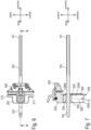
- a surgical instrument system 1 intended for use in a knee joint replacement operation and has an intramedullary rod 100, a reference block 200, at least one bearing element 300, a cutting block 400 and at least one compensation element 500.
- the intramedullary rod 100 is straight elongated between a proximal rod end 101 and a distal rod end 102 and is set up for insertion into a medullary canal of a femur F (see Fig. 3 ).
- the intramedullary rod 100 (hereinafter abbreviated: rod) is aligned coaxially with a proximodistal longitudinal axis of the femur F.
- the distal rod end 102 protrudes from the front end of the femur F and projects beyond its distal condyles, based on Fig. 3 only a lateral distal condyle KL of the femur F is visible.
- the reference block 200 can be pushed onto the rod 100 in the axial direction.
- the reference block 200 has a block back 201, a block front 202, a block top 203, a block bottom 204 and block outsides 205, 206.
- the Block back 201 is oriented proximally. This means that an unspecified surface normal of the back of the block 201 is along a proximodistal axis ( Fig. 1 ) aligned, whereby the alignment, as will be explained in more detail below, does not necessarily have to be parallel.
- the front of the block 202 lies distally opposite the back of the block 201.
- the block top 203 is arranged anterior to the reference block 200.
- the bottom of the block 204 lies posteriorly opposite the top of the block 203.
- the two outer sides of the block 205, 206 lie mediolaterally opposite each other and can also be referred to as the lateral outer side of the block 205 and the medial outer side of the block 206.
- the proximally oriented back of the block 201 is designed to rest on the said distal condyles of the femur F (see Fig. 3 ).
- the reference block 200 is mounted on the distal rod end 102 by means of the bearing element 300.
- the bearing element 300 has a receiving bore 301, which is set up for coaxial and radially positive reception of the distal rod end 102.
- the bearing element 300 is mounted on the reference block 200 so that it can pivot relative to the reference block 200 at least about an anteroposteriorly oriented pivot axis S.
- the bearing element 300 has a proximally oriented back side 302, a distally opposite front side 303, an anteriorly oriented upper side 304, a posteriorly opposite underside 305 and mediolaterally opposite outer sides 306, 307.
- the latter can also be referred to as lateral outside 306 and medial outside 307.
- the receiving hole 301 is along a longitudinal axis L (see Fig. 8 ) extends longitudinally between the back 302 and the front 303.
- the longitudinal axis L and the pivot axis S are aligned orthogonally to one another in the bearing element 300. As will be described in more detail below, different orientations are also provided.
- the bearing element 300 is slidably movable relative to the rod 100.
- the bearing element 300 can basically be rotated in the circumferential direction of the rod 100 about the longitudinal axis L. Apart from this, no relative movement between the bearing element 300 and the rod 100 is possible.
- the reference block 200 Due to the pivotable mounting between the reference block 200 and the bearing element 300, the reference block 200 can be positioned in different angular positions about the pivot axis S relative to the rod 100 and thus also the femur F. This enables a simple and precise adjustment of the varus-valgus angle for the distal resection of the femur F to be subsequently carried out using the cutting block 500.
- the pivot axis S intersects the longitudinal axis L of the receiving hole 301 and thus also the unspecified longitudinal axis of the rod 100.
- a sliding guide with guide surfaces 207, 208 and sliding surfaces 308, 309 is present (see in particular Fig. 5 ).
- the reference block 200 has the guide surfaces 207, 208.
- the bearing element on the other hand, has the sliding surfaces 308, 309.
- the guide surfaces 207, 208 lie mediolaterally opposite each other and are each - with respect to an anterior or posterior direction of view (see Fig. 5 ) - concavely curved in a circular arc.
- the sliding surfaces 308, 309 are shaped complementary to the guide surfaces 207, 208. Accordingly, the sliding surfaces 308, 309 are arranged mediolaterally opposite each other on the bearing element and are convexly curved in the shape of a circular arc.
- the sliding surfaces 308, 309 interact with the guide surfaces 207, 208 in a rotationally slidable manner about the pivot axis S.
- the said surfaces 207, 307, 208, 308 interact in a form-fitting manner proximodistally and thus along the longitudinal axis L. There is also a positive fit in the mediolateral direction.
- the guide surfaces 207, 208 can also be referred to as medial guide surface 207 and lateral guide surface 208.
- the medial guide surface 207 lies on a medial side of the pivot axis S and / or the rod 100.
- the lateral guide surface 208 in contrast, lies on a lateral side of the pivot axis and / or the rod 100.
- the sliding surfaces 308, 309 can also be medial sliding surface 308 and lateral sliding surface 309 are referred to.
- the medial sliding surface 308 is arranged on the medial outside 307 or is formed by it itself. The latter is the case here.
- the lateral sliding surface 309 is formed by the lateral outside 306.
- the guide surfaces 207, 208 each extend straight and longitudinally parallel to the pivot axis S. As a result of the straight and parallel longitudinal extension, they form Guide surfaces 207, 208, as it were, a guide track E extending along the pivot axis S (see in particular Fig. 2 ).
- the reference block 200 and the bearing element 300 can be displaced relative to one another in translation along the guide track E. This allows the reference block 200 to be positioned relative to the rod 100 and thus also to the femur F in different positions with respect to the anteroposterior axis. In other words, the reference block 200 can be positioned differently on the distal femur F with respect to its unspecified vertical axis.
- the reference block 200 is along the guide path E ( Fig. 2 ) can be displaced relative to the bearing element 300 between a lower end position and an upper end position.
- Fig. 3 Positioning in the area of the lower end position is shown. The upper end position is assumed when the reference block 200 starts from the in Fig. 3 position shown is shifted upwards in relation to the drawing plane and until a lower end of the guide surfaces 207, 208 is reached.
- the reference block 200 has a receiving slot 209 extending from the back of the block 201 to the distally opposite front of the block 202.
- the receiving slot 209 is elongated parallel to the pivot axis S and/or the guide track E and has mediolaterally opposite inner walls 2091, 2092, on which the guide surfaces 207, 208 are arranged and/or formed. The latter is the case here.
- the receiving slot has an insertion opening 2093, which is presently arranged on the underside of the block 204.
- the insertion opening 2093 is designed to insert the bearing element 300 into the receiving slot 209.
- the receiving slot 209 also has an end wall 2094.
- the end wall 2094 lies anteriorly opposite the insertion opening 2093 along the pivot axis S.
- the end wall 2094 forms a stop for the bearing element 300, more precisely: its top 304 (see Fig. 7 ).
- the receiving slot 209 divides the reference block 200 into a lateral block section 210 and a medial block section 211 (see in particular Fig. 6 ). Accordingly, the back of the block 201 is divided into a lateral back of the block and a medial back of the block (each without reference numbers).
- the surgical instrument system 1 in the present case has several different bearing elements 300, 300', 300". These can also be referred to as first bearing element 300, second bearing element 300' and third bearing element 300".
- the bearing elements 300, 300', 300" have an essentially identical design and functionality and only differ in terms of the orientation of the longitudinal axis L, L ⁇ , L" of the respective receiving bore 301, 301', 301".
- the longitudinal axes L, L', L" are each longitudinally inclined at different angles. The different angles of inclination are illustrated in relation to a normal direction N of the back of the block 201.
- the normal direction N is in Fig. 8 shown as an example in the second bearing element 300' and the third bearing element 300".
- the normal direction N coincides with the longitudinal axis L.
- the bearing elements 300, 300', 300" can each be attached to the reference block 200 in an interchangeable manner.
- the bearing element 300 can be used - based on the following Fig. 2 configuration shown - can be pulled out of the receiving slot 209 in the posterior direction.
- the assembly is kinematically reversed. Due to the differently inclined longitudinal axes L, L ⁇ , L", the reference block 200 can be positioned at different angles of inclination in relation to the femur F. In particular, the so-called flexion-extension angle can be adjusted easily and precisely.
- the longitudinal axes L, L ⁇ , L" differ from each other in fixed angular steps. Consequently, the adjustment of the angular orientation of the reference block 200 can occur in fixed, defined steps.
- the adjustment of the inclination of the reference block 200 takes place around a mediolaterally aligned axis that intersects both the pivot axis S and the longitudinal axis L.
- the surgical instrument system 1 also has said cutting block 400.
- the function and design of the cutting block 400 is fundamentally known to those skilled in the art.
- the cutting block 400 is used to hold and guide a saw blade for resection of the distal condyles of the femur F.
- the cutting block 400 is detachably attached to the reference block 200 by means of a fixing device 212. Details of the fixing device 212 and the cutting block 400 are not essential to the present invention. Further explanations in this regard can therefore be omitted.
- the compensation element 500 is designed to compensate for wear and tear on the lateral distal condyle KL, which is not shown in more detail, and is releasably attached to the back of the block 201 for this purpose.
- the compensation element has an unspecified proximodistal thickness, which approximately corresponds to the said wear of the lateral condyle KL.
- the surgical instrument system 1 in the present case has several different compensation elements 500, 500', 500" (see Fig. 4 ). This is purely for graphical reasons For reasons only the compensation element 500 is shown in detail.
- the compensation elements 500, 500', 500" have different proximodistal thicknesses and can be attached to the back of the block 201 in an interchangeable manner.
- the compensation elements 500, 500', 500" and their attachment to the back of the block 201 are not essential with regard to the present invention. Further discussions in this regard can therefore be dispensed with.
- the intramedullary rod 100 has a length of 175 mm. In embodiments not shown in the drawing, the length is between 120 mm and 250 mm.
- the Fig. 9 to 14 show a further embodiment of a surgical instrument system 1a according to the invention. Its function and design are essentially identical to the surgical instrument system 1 according to Fig. 1 to 7 . In order to avoid repetitions, the following will primarily focus on essential differences between the surgical instrument system 1a and the surgical instrument system 1 according to the Fig. 1 to 7 received. Functionally identical components and/or sections are marked with identical reference numbers with the addition of the lowercase letter “a”. Functionally identical components and/or sections are not explained separately. Instead, reference is expressly made to what was said about the surgical instrument system 1.
- the surgical instrument system 1a differs primarily in a different implementation of the pivoting mobility between the reference block 200a and the bearing element 300a.
- an axle guide is provided for the purpose of pivoting storage.
- the axle guide has axle elements 220a, 221a oriented coaxially to the pivot axis S and corresponding axle mounts 320a, 321a (see in particular Fig. 12 ).
- the axis elements 220a, 221a are assigned to the reference block 200a.
- the axle mounts 320a, 321a are arranged and/or formed on the bearing element 300a.
- the axle elements 220a, 221a are aligned coaxially with one another.
- the axle elements 220a, 221a and the axle mounts 320a, 321a work together in a sliding manner about the pivot axis S.
- one of the axle elements 220a, 221a engages axially in one of the axle receptacles 320a, 321a.
- Both the axle elements 220a, 221a and the axle receptacles 320a, 321a are in the present case aligned orthogonally to the longitudinal axis of the receiving bore 301a.
- axle mounts 320a, 321a In relation to the longitudinal axis L, one can also speak of an anterior axle element 220a and a posterior axle element 221a. This also applies mutatis mutandis to the axle mounts 320a, 321a.
- the anterior axle mount 320a is sunk posteriorly into an upper side 304a of the bearing element 300a.
- the posterior axle mount 321a is sunk anteriorly into an underside 305a of the bearing element 301a. Both axle mounts 320a, 321a are each introduced into the bearing element 300a in the form of a blind hole.
- the axle elements 220a, 221a are each detachably fixed to the reference block 200a and, in the present case, are each screwed in the form of a countersunk screw to a suitable thread of the reference block 200a. To release the axle elements 220a, 221a, they are each equipped with an unspecified tool surface for receiving a complementary tool.
- the bearing element 300a is mounted in a hollow cylindrical projection 222a of the reference block 200a.
- the projection 222a has a receiving recess 223a ( Fig. 14 ), in which the bearing element 300a is pivotally mounted in the manner described above.
- the receiving recess 223a opens in the proximal direction into a passage 224a ( Fig. 14 ).
- the passage 224a serves to accommodate the distal rod end 102a, which can be guided starting from the back of the block 201a through the passage 224a and from there further via the receiving bore 301a through the reference block 200a.
- the bearing element 300a is not mounted on the reference block 200a so as to be linearly displaceable anteroposteriorly along the pivot axis S.
- the fixing device 212a can be moved accordingly relative to the reference block 200a.
- the reference block 200a has guide holes 225a ( Fig. 10 ), in which guide pins 2121a of the fixing device 212a engage axially.
- compensation element 500a With regard to the function of the compensation element 500a, what has been said about the surgical instrument system 1 applies accordingly. In addition, several different compensation elements with different proximodistal thicknesses can be present.
- the surgical instrument system 1a can in turn have several different bearing elements with differently inclined longitudinal axes, which can be attached to the reference block 200a in an interchangeable manner.
- the axle elements can be detached from the reference block 200a and reattached. This is done using the screw connection described above.
Landscapes
- Health & Medical Sciences (AREA)
- Surgery (AREA)
- Life Sciences & Earth Sciences (AREA)
- Biomedical Technology (AREA)
- Medical Informatics (AREA)
- Oral & Maxillofacial Surgery (AREA)
- Nuclear Medicine, Radiotherapy & Molecular Imaging (AREA)
- Transplantation (AREA)
- Physical Education & Sports Medicine (AREA)
- Engineering & Computer Science (AREA)
- Orthopedic Medicine & Surgery (AREA)
- Heart & Thoracic Surgery (AREA)
- Dentistry (AREA)
- Molecular Biology (AREA)
- Animal Behavior & Ethology (AREA)
- General Health & Medical Sciences (AREA)
- Public Health (AREA)
- Veterinary Medicine (AREA)
- Surgical Instruments (AREA)
- Prostheses (AREA)
Applications Claiming Priority (1)
| Application Number | Priority Date | Filing Date | Title |
|---|---|---|---|
| DE102022205193.9A DE102022205193A1 (de) | 2022-05-24 | 2022-05-24 | Chirurgisches Instrumentensystem |
Publications (1)
| Publication Number | Publication Date |
|---|---|
| EP4282347A1 true EP4282347A1 (fr) | 2023-11-29 |
Family
ID=86497629
Family Applications (1)
| Application Number | Title | Priority Date | Filing Date |
|---|---|---|---|
| EP23174532.4A Pending EP4282347A1 (fr) | 2022-05-24 | 2023-05-22 | Système d'instrument chirurgical |
Country Status (4)
| Country | Link |
|---|---|
| US (1) | US20230380845A1 (fr) |
| EP (1) | EP4282347A1 (fr) |
| JP (1) | JP2023172961A (fr) |
| DE (1) | DE102022205193A1 (fr) |
Citations (5)
| Publication number | Priority date | Publication date | Assignee | Title |
|---|---|---|---|---|
| WO1997021390A1 (fr) * | 1995-12-08 | 1997-06-19 | Wright Medical Technology, Inc. | Appareillage de mesure femorale distale et de resections femorales anterieure et distale |
| DE69722052T2 (de) * | 1996-02-20 | 2004-04-08 | Depuy Products, Inc., Warsaw | Lokalisierungseinrichtung für den Femur |
| DE69636636T2 (de) * | 1995-02-15 | 2007-08-23 | Smith & Nephew, Inc., Memphis | Führung zum Schneiden der Knieschenkeloberfläche |
| US20160030053A1 (en) * | 2014-07-31 | 2016-02-04 | Zimmer, Inc. | Instruments and methods in performing kinematically-aligned total knee arthroplasty |
| DE102015100049A1 (de) * | 2015-01-06 | 2016-07-07 | Waldemar Link Gmbh & Co. Kg | Lehre für die Bestimmung einer für einen Patienten passenden Implantatgröße des Femurimplantats einer Knie-Endoprothese |
Family Cites Families (2)
| Publication number | Priority date | Publication date | Assignee | Title |
|---|---|---|---|---|
| US7011664B2 (en) | 2003-01-31 | 2006-03-14 | Zimmer Technology, Inc. | Resection guide alignment apparatus |
| EP3216426B1 (fr) | 2006-09-06 | 2019-06-12 | Smith & Nephew, Inc | Implants avec surfaces de transition et guide de resection apparenté |
-
2022
- 2022-05-24 DE DE102022205193.9A patent/DE102022205193A1/de active Pending
-
2023
- 2023-05-22 EP EP23174532.4A patent/EP4282347A1/fr active Pending
- 2023-05-23 US US18/321,963 patent/US20230380845A1/en active Pending
- 2023-05-24 JP JP2023085613A patent/JP2023172961A/ja active Pending
Patent Citations (6)
| Publication number | Priority date | Publication date | Assignee | Title |
|---|---|---|---|---|
| DE69636636T2 (de) * | 1995-02-15 | 2007-08-23 | Smith & Nephew, Inc., Memphis | Führung zum Schneiden der Knieschenkeloberfläche |
| WO1997021390A1 (fr) * | 1995-12-08 | 1997-06-19 | Wright Medical Technology, Inc. | Appareillage de mesure femorale distale et de resections femorales anterieure et distale |
| DE69722052T2 (de) * | 1996-02-20 | 2004-04-08 | Depuy Products, Inc., Warsaw | Lokalisierungseinrichtung für den Femur |
| US20160030053A1 (en) * | 2014-07-31 | 2016-02-04 | Zimmer, Inc. | Instruments and methods in performing kinematically-aligned total knee arthroplasty |
| US10130375B2 (en) | 2014-07-31 | 2018-11-20 | Zimmer, Inc. | Instruments and methods in performing kinematically-aligned total knee arthroplasty |
| DE102015100049A1 (de) * | 2015-01-06 | 2016-07-07 | Waldemar Link Gmbh & Co. Kg | Lehre für die Bestimmung einer für einen Patienten passenden Implantatgröße des Femurimplantats einer Knie-Endoprothese |
Also Published As
| Publication number | Publication date |
|---|---|
| DE102022205193A1 (de) | 2023-11-30 |
| US20230380845A1 (en) | 2023-11-30 |
| JP2023172961A (ja) | 2023-12-06 |
Similar Documents
| Publication | Publication Date | Title |
|---|---|---|
| EP0928172B1 (fr) | Prothese d'articulation du genou sans tige | |
| DE60312628T2 (de) | Vorrichtung zum Ausrichten des Beines für eine unikondylare Arthroplastie des Knies | |
| DE60224470T2 (de) | Hüftimplantataufbau | |
| DE60126527T2 (de) | Modulare Gelenkprothese | |
| DE69831107T2 (de) | Tibialen Resektionsführung | |
| EP1304964A1 (fr) | Dispositif pour aligner un gabarit de guidage | |
| DE4038037A1 (de) | Kniegelenkendoprothese | |
| WO2013075925A1 (fr) | Dispositif de définition d'un plan de coupe pour la résection osseuse | |
| DE10057675A1 (de) | Kniegelenk-Endoprothesensystem | |
| EP1284690A1 (fr) | Instruments pour mettre en place une prothese cotyloidienne | |
| EP2515771A1 (fr) | Dispositif de guidage de coupe fémorale pour des opérations de révision dans le domaine des endoprothèses du genou | |
| EP2213262B1 (fr) | Prothèse de genou | |
| DE202021101423U1 (de) | Geführte Fräsvorrichtung für prothetische Chirurgie | |
| EP4245229A1 (fr) | Instrument chirurgical | |
| EP4282347A1 (fr) | Système d'instrument chirurgical | |
| DE69531388T2 (de) | Tibiaresektionsinstrument | |
| WO2010003256A1 (fr) | Dispositif de stimulation d'opérations d'arthroplastie | |
| EP4311506A2 (fr) | Instrument chirurgical et système d'instrument chirurgical | |
| EP4282346A1 (fr) | Instrument chirurgical | |
| DE102022207577A1 (de) | Chirurgisches Instrument, femorales Probeimplantat und chirurgisches Instrumentensystem | |
| EP4285845A1 (fr) | Instrument chirurgical | |
| EP4311507A1 (fr) | Instrument chirurgical | |
| EP4282348A2 (fr) | Instrument chirurgical | |
| EP4311526A1 (fr) | Implant fémoral à sonde condyle | |
| EP4285844A1 (fr) | Instrument chirurgical |
Legal Events
| Date | Code | Title | Description |
|---|---|---|---|
| PUAI | Public reference made under article 153(3) epc to a published international application that has entered the european phase |
Free format text: ORIGINAL CODE: 0009012 |
|
| STAA | Information on the status of an ep patent application or granted ep patent |
Free format text: STATUS: THE APPLICATION HAS BEEN PUBLISHED |
|
| AK | Designated contracting states |
Kind code of ref document: A1 Designated state(s): AL AT BE BG CH CY CZ DE DK EE ES FI FR GB GR HR HU IE IS IT LI LT LU LV MC ME MK MT NL NO PL PT RO RS SE SI SK SM TR |
|
| STAA | Information on the status of an ep patent application or granted ep patent |
Free format text: STATUS: REQUEST FOR EXAMINATION WAS MADE |