EP4282347A1 - Surgical instrument system - Google Patents
Surgical instrument system Download PDFInfo
- Publication number
- EP4282347A1 EP4282347A1 EP23174532.4A EP23174532A EP4282347A1 EP 4282347 A1 EP4282347 A1 EP 4282347A1 EP 23174532 A EP23174532 A EP 23174532A EP 4282347 A1 EP4282347 A1 EP 4282347A1
- Authority
- EP
- European Patent Office
- Prior art keywords
- block
- reference block
- surgical instrument
- instrument system
- bearing element
- Prior art date
- Legal status (The legal status is an assumption and is not a legal conclusion. Google has not performed a legal analysis and makes no representation as to the accuracy of the status listed.)
- Pending
Links
- 210000000689 upper leg Anatomy 0.000 claims abstract description 31
- 238000003780 insertion Methods 0.000 claims abstract description 13
- 230000037431 insertion Effects 0.000 claims abstract description 13
- 210000000629 knee joint Anatomy 0.000 claims abstract description 12
- 238000001356 surgical procedure Methods 0.000 claims 1
- 238000013459 approach Methods 0.000 description 8
- 230000000295 complement effect Effects 0.000 description 5
- 230000000399 orthopedic effect Effects 0.000 description 4
- 210000002303 tibia Anatomy 0.000 description 3
- 210000003484 anatomy Anatomy 0.000 description 2
- 210000000988 bone and bone Anatomy 0.000 description 2
- 238000002271 resection Methods 0.000 description 2
- 238000011883 total knee arthroplasty Methods 0.000 description 2
- 210000004394 hip joint Anatomy 0.000 description 1
- 230000001771 impaired effect Effects 0.000 description 1
- 238000004519 manufacturing process Methods 0.000 description 1
Images


Classifications
-
- A—HUMAN NECESSITIES
- A61—MEDICAL OR VETERINARY SCIENCE; HYGIENE
- A61B—DIAGNOSIS; SURGERY; IDENTIFICATION
- A61B17/00—Surgical instruments, devices or methods, e.g. tourniquets
- A61B17/14—Surgical saws ; Accessories therefor
- A61B17/15—Guides therefor
- A61B17/154—Guides therefor for preparing bone for knee prosthesis
- A61B17/155—Cutting femur
Landscapes
- Health & Medical Sciences (AREA)
- Surgery (AREA)
- Life Sciences & Earth Sciences (AREA)
- Biomedical Technology (AREA)
- Medical Informatics (AREA)
- Oral & Maxillofacial Surgery (AREA)
- Nuclear Medicine, Radiotherapy & Molecular Imaging (AREA)
- Transplantation (AREA)
- Physical Education & Sports Medicine (AREA)
- Engineering & Computer Science (AREA)
- Orthopedic Medicine & Surgery (AREA)
- Heart & Thoracic Surgery (AREA)
- Dentistry (AREA)
- Molecular Biology (AREA)
- Animal Behavior & Ethology (AREA)
- General Health & Medical Sciences (AREA)
- Public Health (AREA)
- Veterinary Medicine (AREA)
- Surgical Instruments (AREA)
- Prostheses (AREA)
Abstract
2.1 Ein derartiges chirurgisches Instrumentensystem zur Verwendung bei einer Kniegelenkersatzoperation, aufweisend einen intramedullären Stab, welcher zwischen einem proximalen Stabende und einem distalen Stabende längserstreckt und zum Einbringen in den Markraum eines Femurs eingerichtet ist, und einen auf das distale Stabende aufgeschobenen oder aufschiebbaren Referenzblock mit einer proximal orientierten Blockrückseite, welche zur Anlage an distalen Kondylen des Femurs eingerichtet ist, ist bekannt.2.2 Erfindungsgemäß ist der Referenzblock mittels eines Lagerelements an dem distalen Stabende gelagert oder lagerbar, wobei das Lagerelement eine Aufnahmebohrung zur koaxialen und radial formschlüssigen Aufnahme des distalen Stabendes aufweist und relativ zu dem Referenzblock wenigstens um eine anteroposterior orientierte Schwenkachse schwenkbeweglich an demselben gelagert ist.2.3 Verwendung bei einer Kniegelenkersatzoperation2.1 Such a surgical instrument system for use in a knee joint replacement operation, comprising an intramedullary rod which extends longitudinally between a proximal rod end and a distal rod end and is set up for insertion into the medullary canal of a femur, and a reference block which is pushed or can be pushed onto the distal rod end and has a proximal oriented back of the block, which is set up to rest on distal condyles of the femur, is known.2.2 According to the invention, the reference block is mounted or can be stored on the distal end of the rod by means of a bearing element, the bearing element having a receiving bore for coaxial and radially positive reception of the distal end of the rod and relatively is mounted on the reference block so that it can pivot at least about an anteroposteriorly oriented pivot axis.2.3 Use in a knee joint replacement operation
Description
Die Erfindung betrifft ein chirurgisches Instrumentensystem zur Verwendung bei einer Kniegelenkersatzoperation, aufweisend einen intramedullären Stab, welcher zwischen einem proximalen Stabende und einem distalen Stabende längserstreckt und zum Einbringen in den Markraum eines Femurs eingerichtet ist, und einen auf das distale Stabende aufgeschobenen oder aufschiebbaren Referenzblock mit einer proximal orientierten Blockrückseite, welche zur Anlage an distalen Kondylen des Femurs eingerichtet ist.The invention relates to a surgical instrument system for use in a knee joint replacement operation, comprising an intramedullary rod which extends longitudinally between a proximal rod end and a distal rod end and is set up for insertion into the medullary canal of a femur, and a reference block which is pushed or can be pushed onto the distal rod end and has a Proximal oriented back of the block, which is designed to rest on the distal condyles of the femur.
Die Verwendung orthopädischer Prothesen als künstlicher Ersatz für beschädigte oder abgenutzte natürlichen Knochenstrukturen eines Patienten ist gängige medizinische Praxis. Insbesondere Hüft- und Kniegelenkersatzoperationen gehören mittlerweile zum Standardrepertoire der chirurgischen Orthopädie.The use of orthopedic prostheses as artificial replacements for a patient's damaged or worn-out natural bone structures is common medical practice. Hip and knee joint replacement operations in particular are now part of the standard repertoire of surgical orthopedics.
Bei einer Kniegelenkersatzoperation (englisch: Total Knee Arthroplasty (TKA)) werden abgenutzte oder anderweitig durch Krankheit oder einen Unfall beeinträchtigte Gelenkflächen des Femurs und/oder der Tibia durch eine Kniegelenkprothese ersetzt. Solche Kniegelenkprothesen umfassen üblicherweise eine Femurkomponente, welche am distalen Ende des Femurs implantiert wird, und eine Tibiakomponente, welche am proximalen Ende der Tibia implantiert wird. Um eine einwandfreie Funktion des künstlichen Gelenkersatzes zu gewährleisten, müssen die besagten Komponenten hinsichtlich ihrer Lage und Orientierung in Bezug auf die Anatomie des Patienten und dessen Körperachsen in definierter Weise möglichst präzise positioniert werden. Andernfalls ist mit einem für den Patienten nicht zufriedenstellenden Ergebnis zu rechnen. Hinsichtlich der Positionierung der Komponenten existieren unterschiedliche chirurgische Ansätze.During total knee arthroplasty (TKA), worn or otherwise impaired articular surfaces of the femur and/or tibia are replaced by a knee joint prosthesis. Such knee joint prostheses typically include a femoral component implanted at the distal end of the femur and a tibial component implanted at the proximal end of the tibia. In order to ensure proper functioning of the artificial joint replacement, the components in question must be positioned as precisely as possible in a defined manner with regard to their position and orientation in relation to the anatomy of the patient and his body axes. Otherwise, an unsatisfactory result for the patient can be expected. There are different surgical approaches regarding the positioning of the components.
Ein als Mechanical Alignment bekannter und bislang üblicher Ansatz sieht vor, dass die Position und Ausrichtung der künstlichen Gelenkachsen der Kniegelenkprothese mechanisch ideal und insoweit ohne Berücksichtigung etwaiger orthopädischer Fehlstellungen des Patienten ausgerichtet werden. Hierbei dient oftmals die Längsachse der Tibia als Referenzachse für die Ausrichtung und Positionierung. Klinische Studien haben gezeigt, dass der Mechanical Alignment-Ansatz zu einer als unnatürlich empfundenen Funktion des künstlichen Kniegelenks führen kann.An approach known as mechanical alignment and which has been common to date envisages that the position and alignment of the artificial joint axes of the knee joint prosthesis are aligned in a mechanically ideal manner and to this extent without taking any orthopedic misalignments of the patient into account. The longitudinal axis of the tibia often serves as a reference axis for alignment and positioning. Clinical studies have shown that the mechanical alignment approach can lead to the function of the artificial knee joint being perceived as unnatural.
Als ein weiterer Ansatz ist das sog. Kinematic Alignment bekannt. Bei dieser Vorgehensweise werden die Femurkomponente und die Tibiakomponente unter Berücksichtigung etwaiger orthopädischer Fehlstellungen des Patienten positioniert. Ziel hierbei ist es, die natürliche und unter Umständen mit Fehlstellungen behaftete Gelenkausrichtung des Patienten wiederherzustellen. Klinische Studien haben gezeigt, dass der Kinematic Alignment-Ansatz oftmals mit einer verbesserten Patientenzufriedenheit einhergeht. Insbesondere die Funktion des künstlichen Kniegelenks wird seitens der Patienten als eher natürlich empfunden.Another approach is known as kinematic alignment. In this approach, the femoral component and the tibial component are positioned taking into account any orthopedic misalignments in the patient. The aim here is to restore the patient's natural joint alignment, which may be affected by misalignments. Clinical studies have shown that the Kinematic Alignment approach is often associated with improved patient satisfaction. In particular, patients perceive the function of the artificial knee joint as rather natural.
Mit dem Bestreben, die Patientenzufriedenheit weiter zu verbessern, geht ein grundsätzlicher Bedarf nach möglichst präzisen, einfach verwendbaren und kosteneffizienten chirurgischen Instrumenten und Instrumentensystemen zur Umsetzung des Kinematic Alignment einher.The desire to further improve patient satisfaction is accompanied by a fundamental need for surgical instruments and instrument systems that are as precise, easy to use and cost-effective as possible to implement kinematic alignment.
Die vorliegende Erfindung befasst sich mit solchen chirurgischen Instrumentensystemen, im Speziellen mit einem chirurgischen Instrumentensystem zur Positionierung eines distalen Femurschnittblocks im Rahmen des Kinematic Alignment.The present invention deals with such surgical instrument systems, in particular with a surgical instrument system for positioning a distal femur incision block as part of kinematic alignment.
Ein derartiges chirurgisches Instrumentensystem ist aus der
Aufgabe der Erfindung ist es, ein chirurgisches Instrumentensystem der eingangs genannten Art bereitzustellen, welches eine präzise Einstellung der Lage und Orientierung des Referenzblocks und letztlich verbesserte Operationsergebnisse ermöglicht.The object of the invention is to provide a surgical instrument system of the type mentioned at the outset, which enables precise adjustment of the position and orientation of the reference block and ultimately improved surgical results.
Diese Aufgabe wird dadurch gelöst, dass der Referenzblock mittels eines Lagerelements an dem distalen Stabende gelagert oder lagerbar ist, wobei das Lagerelement eine Aufnahmebohrung zur koaxialen und radial formschlüssigen Aufnahme des distalen Stabendes aufweist und relativ zu dem Referenzblock wenigstens um eine anteroposterior orientierte Schwenkachse schwenkbeweglich an demselben gelagert ist. Durch die erfindungsgemäße Lösung wird eine verbesserte Lagerung des Referenzblocks an dem intramedullären Stab erreicht. Im Vergleich zu aus dem Stand der Technik bekannten Lösungen ermöglicht die Erfindung eine kinematisch wohldefinierte Relativbeweglichkeit des Referenzblocks. Hierdurch können die Lage und Orientierung des Referenzblocks präzise eingestellt werden. Insbesondere kann durch die Schwenkbeweglichkeit des Referenzblocks um die anteroposterior orientierte Schwenkachse der sogenannte Varus-Valgus-Winkel präzise eingestellt werden. Hierdurch werden Fehlausrichtungen der kinematischen Achsen des Kniegelenkersatzes vermieden und letztlich verbesserte Operationsergebnisse ermöglicht. Der Referenzblock ist mittelbar, nämlich mittels des Lagerelements, an dem intramedullären Stab gelagert oder lagerbar. Zu diesem Zweck weist das Lagerelement die besagte Aufnahmebohrung auf. Die Aufnahmebohrung ist maßlich komplementär zu dem intramedullären Stab gestaltet. In aufgeschobenem Zustand des Referenzblocks sind die Aufnahmebohrung und der intramedulläre Stab koaxial zueinander ausgerichtet und der intramedulläre Stab ist radial formschlüssig in der Aufnahmebohrung aufgenommen. Infolge des Formschlusses sind das Lagerelement und der intramedulläre Stab mediolateral sowie anteroposterior relativ zueinander festgelegt. Die besagte Schwenkbeweglichkeit des Referenzblocks in Relation zu dem intramedullären Stab wird durch die schwenkbewegliche Lagerung des Lagerelements an dem Referenzblock ermöglicht. Die Lagerung kann beispielsweise als Gleitführung, Achsführung oder dergleichen ausgebildet sein und Bauteile und/oder Abschnitte umfassen, die zum einen an dem Referenzblock und zum anderen an dem Lagerelement angeordnet und/oder ausgebildet sind.This object is achieved in that the reference block is mounted or can be stored on the distal rod end by means of a bearing element, the bearing element having a receiving bore for coaxial and radially positive reception of the distal rod end and being pivotable relative to the reference block at least about an anteroposteriorly oriented pivot axis on the same is stored. The solution according to the invention achieves improved positioning of the reference block on the intramedullary rod. In comparison to solutions known from the prior art, the invention enables a kinematically well-defined relative mobility of the reference block. This allows the position and orientation of the reference block to be set precisely. In particular, the so-called varus-valgus angle can be precisely adjusted due to the pivoting mobility of the reference block about the anteroposteriorly oriented pivot axis. This avoids misalignments of the kinematic axes of the knee joint replacement and ultimately enables improved surgical results. The reference block is mounted or can be stored indirectly, namely by means of the bearing element, on the intramedullary rod. For this purpose, the bearing element has the said receiving hole. The receiving hole is dimensionally complementary to the intramedullary rod. When the reference block is pushed on, the receiving hole and the intramedullary rod are coaxially aligned with one another and the intramedullary rod is received in the receiving hole in a radially positive manner. As a result of the positive fit, the bearing element and the intramedullary rod are fixed mediolaterally and anteroposteriorly relative to one another. The said pivoting mobility of the reference block in relation to the intramedullary rod is made possible by the pivotable mounting of the bearing element on the reference block. The bearing can, for example, be designed as a sliding guide, axle guide or the like and include components and/or sections which are arranged and/or formed on the one hand on the reference block and on the other hand on the bearing element.
Die in dieser Beschreibung verwendeten Lage- und Richtungsbezeichnungen beziehen sich auf den Körper eines Patienten, insbesondere dessen Femur, und sind insoweit gemäß ihrer üblichen anatomischen Bedeutung zu verstehen. Folglich bedeutet "anterior" vordere(r) oder vorne liegend, "posterior" hintere(r) oder hinten liegend, "medial" innere(r) oder innen liegend, "lateral" äußere(r) oder außen liegend, "proximal" zum Körperzentrum hin und "distal" vom Körperzentrum entfernt. Weiter bedeuten "proximodistal" entlang, vorzugsweise parallel zu, einer proximal-distal ausgerichteten Achse, "anteroposterior" entlang, vorzugsweise parallel zu, einer anterior-posterior ausgerichteten Achse und "mediolateral" entlang, vorzugsweise parallel zu, einer medial-lateral ausgerichteten Achse. Die besagten Achsen sind orthogonal zueinander ausgerichtet und können selbstverständlich in Bezug zu nicht mit der Anatomie des Patienten in Verbindung stehenden X-, Y- und Z-Achsen gesetzt werden. Beispielsweise kann die proximaldistale Achse alternativ als X-Achse bezeichnet werden. Die medial-laterale Achse kann als Y-Achse bezeichnet werden. Die anterior-posteriore Achse kann als Z-Achse bezeichnet werden. Zur verbesserten Veranschaulichung und der Einfachheit der Bezeichnung wegen werden nachfolgend in erster Linie die besagten anatomischen Lage- und Richtungsbezeichnungen verwendet. Weiter werden Bezeichnungen wie "Rückseite" einer Komponente oder eines Abschnitts des chirurgischen Instrumentensystems, beispielsweise des Referenzblocks, in Bezug auf eine proximal gerichtete Blickrichtung verwendet. Dementgegen werden Bezeichnungen wie "Vorderseite" in Bezug auf eine distal gerichtete Blickrichtung verwendet.The position and direction designations used in this description refer to the body of a patient, in particular the femur, and are to be understood in accordance with their usual anatomical meaning. Consequently, "anterior" means front or lying in front, "posterior" means back or lying behind, "medial" means inside or inside, "lateral" means outside or outside, "proximal" to body center towards and "distally" away from the body center. Furthermore, “proximodistal” means along, preferably parallel to, a proximal-distal oriented axis, “anteroposterior” along, preferably parallel to, an anterior-posterior oriented axis and “mediolateral” along, preferably parallel to, a medial-lateral oriented axis. The axes in question are aligned orthogonally to one another and of course cannot be related to the anatomy of the patient The associated X, Y and Z axes can be set. For example, the proximal-distal axis may alternatively be referred to as the X-axis. The medial-lateral axis can be referred to as the Y axis. The anterior-posterior axis can be called the Z axis. For improved illustration and for the sake of simplicity of the designation, the above-mentioned anatomical position and direction designations are primarily used below. Furthermore, terms such as “back” of a component or a section of the surgical instrument system, for example the reference block, are used in relation to a proximally directed viewing direction. In contrast, terms such as “front” are used in reference to a distal viewing direction.
In Ausgestaltung der Erfindung weist der Referenzblock eine Gleitführung mit mediolateral gegenüberliegenden kreisbogenförmig konkav gekrümmten Führungsflächen auf, und das Lagerelement weist mediolateral gegenüberliegende kreisbogenförmig konvex gekrümmte Gleitflächen auf, wobei die Gleitflächen und die Schwenkachse rotatorisch gleitbeweglich und proximodistal sowie mediolateral translatorisch formschlüssig mit den Führungsflächen zusammenwirken. Hierdurch wird eine konstruktiv besonders einfache und dennoch präzise und robuste schwenkbewegliche Lagerung zwischen dem Lagerelement und dem Referenzblock erreicht. Die Führungsflächen und die Gleitflächen sind jeweils in Bezug auf eine anterior oder posterior gerichtete Blickrichtung kreisbogenförmig. Die Führungsflächen und die Gleitflächen sind zueinander komplementär gekrümmt, wobei die Führungsflächen konkav und die Gleitflächen jeweils konvex sind. Die Führungsflächen definieren einen Innendurchmesser der Gleitführung. Die Gleitflächen definieren einen komplementären Außendurchmesser. Der Außendurchmesser ist in den Innendurchmesser eingepasst. Die Passung ist vorzugsweise derart gewählt, dass eine präzise, spielfreie und gleichzeitig ausreichend leichtgängige Relativbeweglichkeit zwischen dem Lagerelement und dem Referenzblock erreicht ist. Vorzugsweise ist die Aufnahmebohrung in mediolateraler Richtung, bevorzugt mittig, zwischen den gegenüberliegenden Gleitflächen des Lagerelements angeordnet. Die gegenüberliegenden Führungsflächen können auch als erste Führungsfläche und zweite Führungsfläche oder alternativ als mediale Führungsfläche und laterale Führungsfläche bezeichnet werden. Entsprechendes gilt mutatis mutandis hinsichtlich der Gleitflächen.In an embodiment of the invention, the reference block has a sliding guide with mediolaterally opposite circular arc-shaped, concavely curved guide surfaces, and the bearing element has mediolaterally opposite circular arc-shaped, convexly curved sliding surfaces, the sliding surfaces and the pivot axis interacting with the guide surfaces in a rotationally slidable manner and in a proximodistal and mediolaterally translational manner. This achieves a structurally particularly simple yet precise and robust pivoting bearing between the bearing element and the reference block. The guide surfaces and the sliding surfaces are each circular arc-shaped with respect to an anterior or posterior viewing direction. The guide surfaces and the sliding surfaces are curved to complement each other, with the guide surfaces being concave and the sliding surfaces each being convex. The guide surfaces define an inner diameter of the sliding guide. The sliding surfaces define a complementary outside diameter. The outside diameter is fitted into the inside diameter. The fit is preferably selected such that precise, play-free and at the same time sufficiently smooth relative mobility is achieved between the bearing element and the reference block. Preferably, the receiving hole is arranged in the mediolateral direction, preferably centrally, between the opposing sliding surfaces of the bearing element. The opposing guide surfaces can also be referred to as the first guide surface and the second guide surface or alternatively as the medial guide surface and the lateral guide surface. The same applies mutatis mutandis with regard to the sliding surfaces.
In weiterer Ausgestaltung der Erfindung sind die Führungsflächen jeweils parallel zu der Schwenkachse gerade längserstreckt, wobei die Gleitflächen entlang der Schwenkachse translatorisch beweglich mit den Führungsflächen zusammenwirken. Hierdurch ist der Referenzblock anteroposterior relativ zu dem intramedullären Stab gleitbeweglich. Dies erlaubt eine Einstellung der anteroposterioren Position des Referenzblocks. Hierdurch ist die Positionierung des Referenzblocks in verbesserter Weise an eine gegebene Größe des Femurs anpassbar. Infolge ihrer geraden Längserstreckung bilden die gegenüberliegenden Führungsflächen gleichsam jeweils eine Führungsbahn. Der Referenzblock ist entlang der Schwenkachse und/oder der Führungsbahn zwischen einer oberen Endlage und einer unteren Endlage relativ zu dem Lagerelement translatorisch verlagerbar.In a further embodiment of the invention, the guide surfaces each extend straight, parallel to the pivot axis, with the sliding surfaces interacting with the guide surfaces in a translationally movable manner along the pivot axis. This allows the reference block to slide anteroposteriorly relative to the intramedullary rod. This allows adjustment of the anteroposterior position of the reference block. This is the Positioning of the reference block can be adapted in an improved manner to a given size of the femur. As a result of their straight longitudinal extent, the opposing guide surfaces each form a guide track, so to speak. The reference block is translationally displaceable relative to the bearing element along the pivot axis and/or the guide track between an upper end position and a lower end position.
In weiterer Ausgestaltung der Erfindung weist der Referenzblock einen von der Blockrückseite auf eine distal gegenüberliegende Blockvorderseite reichenden sowie parallel zu der Schwenkachse gerade längserstreckten Aufnahmeschlitz mit mediolateral gegenüberliegenden Innenwandungen auf, an welchen die Führungsflächen angeordnet und/oder ausgebildet sind, wobei der Aufnahmeschlitz zum Einführen des Lagerelements eine anterior an einer Blockoberseite oder posterior an einer Blockunterseite des Referenzblocks angeordnete Einführöffnung aufweist. Der Aufnahmeschlitz ermöglicht eine besonders einfache und zeitsparende Anbringung des Lagerelements an dem Referenzblock oder umgekehrt. Beispielsweise kann zunächst das Lagerelement mit der Aufnahmebohrung voran in proximaler Richtung auf das distale Stabende aufgeschoben werden. Hiernach kann der Referenzblock entlang der Schwenkachse anterior oder posterior, je nachdem ob die Einführöffnung auf der Blockober- oder -unterseite angeordnet ist, auf das Lagerelement aufgeschoben werden. Alternativ kann das Lagerelement vor dem Aufschieben auf den intramedullären Stab in den Aufnahmeschlitz eingebracht werden. Bei einer Ausgestaltung ist die Einführöffnung an der Blockoberseite des Referenzblocks angeordnet. Bei einer weiteren Ausgestaltung ist die Einführöffnung auf der Blockunterseite angeordnet. Die Blockoberseite und die Blockunterseite liegen einander anteroposterior gegenüber. Vorzugsweise unterteilt der Aufnahmeschlitz den Referenzblock in einen lateralen Blockabschnitt und einen medialen Blockabschnitt. Eine Rückseite des medialen Blockabschnitts ist zur Anlage an der medialen distalen Kondyle des Femurs eingerichtet. Eine Rückseite des lateralen Blockabschnitts ist zur Anlage an der lateralen distalen Kondyle des Femurs eingerichtet.In a further embodiment of the invention, the reference block has a receiving slot that extends from the back of the block to a distally opposite front of the block and extends straight parallel to the pivot axis with mediolaterally opposite inner walls on which the guide surfaces are arranged and / or formed, the receiving slot for inserting the bearing element has an insertion opening arranged anteriorly on a block top or posteriorly on a block underside of the reference block. The receiving slot enables a particularly simple and time-saving attachment of the bearing element to the reference block or vice versa. For example, the bearing element can first be pushed onto the distal rod end in the proximal direction with the receiving hole first. The reference block can then be pushed onto the bearing element along the pivot axis anteriorly or posteriorly, depending on whether the insertion opening is arranged on the top or bottom of the block. Alternatively, the bearing element can be inserted into the receiving slot before being pushed onto the intramedullary rod. In one embodiment, the insertion opening is arranged on the top of the reference block. In a further embodiment, the insertion opening is arranged on the underside of the block. The top of the block and the bottom of the block lie opposite each other anteroposteriorly. Preferably, the receiving slot divides the reference block into a lateral block section and a medial block section. A rear side of the medial block section is adapted to rest on the medial distal condyle of the femur. A rear side of the lateral block section is designed to rest on the lateral distal condyle of the femur.
In weiterer Ausgestaltung der Erfindung weist der Referenzblock eine Achsführung mit wenigstens einem koaxial zu der Schwenkachse orientierten Achselement auf, und das Lagerelement weist wenigstens eine koaxial zu der Schwenkachse orientierte Achsaufnahme auf, wobei das Achselement um die Schwenkachse gleitbeweglich in die Achsaufnahme eingreift. Das Achselement ist vorzugsweise stift-, bolzen- und/oder zapfenförmig gestaltet, so dass auch von einem Achsstift, Achsbolzen oder Achszapfen gesprochen werden kann. Die Achsführung ist konstruktiv vergleichsweise einfach aufgebaut. Dies erlaubt eine einfache Herstellung und Montage sowie damit einhergehende Kosteneinsparungen. Gleichzeitig kann eine dennoch hinreichend präzise schwenkbewegliche Lagerung erreicht werden. Bei einer Ausgestaltung weist der Referenzblock zwei Achselemente und das Lagerelement dementsprechend zwei Achsaufnahmen auf, die mit jeweils einem der Achselemente zusammenwirken. In diesem Zusammenhang kann auch von einem anterioren Achselement und einem posterioren Achselement gesprochen werden. Entsprechendes gilt mutatis mutandis hinsichtlich der Achsaufnahmen. Bei der besagten Ausgestaltung ist die Aufnahmebohrung vorzugsweise anteroposterior, bevorzugt mittig, zwischen der anterioren Achsaufnahme und der posterioren Achsaufnahme angeordnet.In a further embodiment of the invention, the reference block has an axle guide with at least one axle element oriented coaxially to the pivot axis, and the bearing element has at least one axle receptacle oriented coaxially to the pivot axis, the axle element engaging in the axle receptacle so that it can slide about the pivot axis. The axle element is preferably designed in the shape of a pin, bolt and/or peg, so that it can also be referred to as an axle pin, axle bolt or axle journal. The axle guidance is structurally comparatively simple. This allows for easy manufacturing and assembly as well as associated cost savings. At the same time, a sufficiently precise pivoting bearing can still be achieved. At a Embodiment, the reference block has two axle elements and the bearing element accordingly has two axle mounts, each of which interacts with one of the axle elements. In this context one can also speak of an anterior axis element and a posterior axis element. The same applies mutatis mutandis with regard to the axle mounts. In the said embodiment, the receiving hole is preferably arranged anteroposteriorly, preferably centrally, between the anterior axle mount and the posterior axle mount.
In weiterer Ausgestaltung der Erfindung ist das wenigstens eine Lagerelement lösbar an dem Referenzblock gelagert, und es sind mehrere unterschiedliche Lagerelemente mit unterschiedlich geneigt längserstreckten Aufnahmebohrungen vorhanden, welche zur Einstellung eines Neigungswinkels des Referenzblocks an demselben gegeneinander austauschbar lagerbar sind. Die mehreren unterschiedlichen Lagerelemente unterscheiden sich vorzugsweise ausschließlich im Hinblick auf die Neigung der Aufnahmebohrung voneinander. Vorzugsweise sind die unterschiedlichen Lagerelemente im Übrigen identisch. Infolge der unterschiedlich geneigt längserstreckten Aufnahmebohrungen kann der Neigungswinkel des Referenzblocks - durch eine entsprechende Auswahl des jeweiligen Lagerelements - auf einfache und präzise Weise eingestellt werden. Vorzugsweise sind die Aufnahmebohrungen unterschiedlich geneigt in Bezug auf die proximal orientierte Blockrückseite des Referenzblocks. Dabei sind die Aufnahmebohrungen vorzugsweise relativ zu der Normalenrichtung der Blockrückseite unterschiedlich in anteriorer Richtung und/oder posteriorer Richtung geneigt. Dies erlaubt eine einfache und präzise Einstellung des Flexions-Extensions-Winkels des Referenzblocks, d.h. dessen Rotationswinkel um eine mediolateral ausgerichtete Achse.In a further embodiment of the invention, the at least one bearing element is detachably mounted on the reference block, and there are several different bearing elements with differently inclined, longitudinally extending receiving bores, which can be stored on the reference block in an interchangeable manner in order to adjust an angle of inclination of the reference block. The several different bearing elements preferably differ from each other only with regard to the inclination of the receiving bore. Preferably, the different bearing elements are otherwise identical. As a result of the differently inclined, longitudinally extending receiving bores, the angle of inclination of the reference block can be adjusted in a simple and precise manner - by appropriate selection of the respective bearing element. The receiving bores are preferably inclined at different angles in relation to the proximally oriented back of the reference block. The receiving bores are preferably inclined differently in the anterior direction and/or posterior direction relative to the normal direction of the back of the block. This allows a simple and precise adjustment of the flexion-extension angle of the reference block, i.e. its rotation angle about a mediolaterally aligned axis.
In weiterer Ausgestaltung der Erfindung sind mehrere unterschiedliche Kompensationselemente mit unterschiedlichen proximodistalen Dicken vorhanden und zur Kompensation unterschiedlich stark ausgeprägter Abnutzungen der posterioren Kondylen an der Blockrückseite gegeneinander austauschbar anbringbar. Das chirurgische Instrumentensystem ist, wie eingangs erläutert, zur Umsetzung des Kinematic Alignment-Ansatzes vorgesehen. Dieser Ansatz sieht üblicherweise eine maßliche Kompensation der besagten kondylären Abnutzungen vor. Zu diesem Zweck weist das chirurgische Instrumentensystem bei dieser Ausgestaltung der Erfindung mehrere unterschiedliche und gegeneinander austauschbare Kompensationselemente mit unterschiedlicher proximodistaler Dicke auf.In a further embodiment of the invention, several different compensation elements with different proximodistal thicknesses are present and can be attached to the back of the block in an interchangeable manner to compensate for different levels of wear on the posterior condyles. As explained at the beginning, the surgical instrument system is intended to implement the kinematic alignment approach. This approach usually provides for dimensional compensation of the said condylar wear. For this purpose, the surgical instrument system in this embodiment of the invention has several different and interchangeable compensation elements with different proximodistal thicknesses.
In weiterer Ausgestaltung der Erfindung ist ein Schnittblock vorhanden, welcher zu einer Schnittführung an den distalen Kondylen des Femurs eingerichtet und an einer Fixiervorrichtung des Referenzblocks lösbar fixiert oder fixierbar ist. Der Schnittblock kann auch als Sägeblock oder cutting jig bezeichnet werden. Der Schnittblock weist wenigstens einen Führungsschlitz zur Aufnahme und Führung eines Sägeblatts auf. Die grundsätzliche Gestaltung und Funktionsweise eines solchen Schnittblocks sind dem Fachmann bekannt. Die Fixiervorrichtung ist vorzugsweise im Bereich der anterioren Blockoberseite des Referenzblocks angeordnet.In a further embodiment of the invention, a cutting block is present, which is set up to make an incision on the distal condyles of the femur and on a fixing device of the reference block is releasably fixed or fixable. The cutting block can also be called a saw block or cutting jig. The cutting block has at least one guide slot for receiving and guiding a saw blade. The basic design and functionality of such a cutting block are known to those skilled in the art. The fixing device is preferably arranged in the area of the anterior block top of the reference block.
In weiterer Ausgestaltung der Erfindung weist der intramedulläre Stab eine Länge zwischen 120 mm und 250 mm, bevorzugt zwischen 150 mm und 220 mm, besonders bevorzugt zwischen 170 mm und 200 mm, auf.In a further embodiment of the invention, the intramedullary rod has a length between 120 mm and 250 mm, preferably between 150 mm and 220 mm, particularly preferably between 170 mm and 200 mm.
Weitere Vorteile und Merkmale der Erfindung ergeben sich aus den Ansprüchen sowie aus der nachfolgenden Beschreibung bevorzugter Ausführungsbeispiele der Erfindung, die anhand der Zeichnungen darrgestellt sind.
- Fig. 1
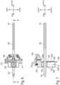
- zeigt in schematischer Perspektivdarstellung eine Ausführungsform eines erfindungsgemäßen chirurgischen Instrumentensystems mit einem intramedullären Stab, einem Referenzblock, einem Lagerelement und einem Schnittblock,
- Fig. 2
- in schematischer Perspektivdarstellung den Referenzblock und das Lagerelement des chirurgischen Instrumentensystems nach
Fig. 1 in einer auf eine Blockrückseite gerichteten Blickrichtung, - Fig. 3
- in schematischer Perspektivdarstellung eine intraoperative Situation unter Verwendung des chirurgischen Instrumentensystems nach
Fig. 1 , - Fig. 4
- das chirurgische Instrumentensystem nach
Fig. 1 in einer schematischen Seitenansicht mit lateral gerichteter Blickrichtung, - Fig. 5
- eine schematische Längsschnittdarstellung entlang einer Schnittlinie B-B gemäß
Fig. 4 , - Fig. 6
- das chirurgische Instrumentensystem nach den
Fig. 1 bis 5 in einer schematischen Aufsicht mit posterior gerichteter Blickrichtung, - Fig. 7
- eine schematische Längsschnittdarstellung entlang einer Schnittlinie A-A gemäß
Fig. 6 , - Fig. 8
- in schematischer Perspektivdarstellung unterschiedliche Lagerelemente mit unterschiedlich geneigten Aufnahmebohrungen,
- Fig. 9
- in schematischer Perspektivdarstellung eine weitere Ausführungsform eines erfindungsgemäßen chirurgische Instrumentensystems in einer intraoperativen Situation,
- Fig. 10
- in schematischer Perspektivdarstellung den Referenzblock und das Lagerelement des chirurgischen Instrumentensystems nach
Fig. 9 , - Fig. 11
- das chirurgische Instrumentensystem nach
Fig. 9 in einer schematischen Aufsicht mit posterior gerichteter Blickrichtung, - Fig. 12
- ein schematischer Längsschnitt entlang einer Schnittlinie A-A gemäß
Fig. 11 , - Fig. 13
- das chirurgische Instrumentensystem nach den
Fig. 9 in einer schematischen Seitenansicht mit medial gerichteter Blickrichtung undbis 12 - Fig. 14
- eine schematische Längsschnittdarstellung entlang einer Schnittlinie C-C gemäß
Fig. 13 .
- Fig. 1
- shows a schematic perspective view of an embodiment of a surgical instrument system according to the invention with an intramedullary rod, a reference block, a bearing element and a cutting block,
- Fig. 2
- a schematic perspective view of the reference block and the bearing element of the surgical instrument system
Fig. 1 in a viewing direction directed towards the back of a block, - Fig. 3
- shows a schematic perspective view of an intraoperative situation using the surgical instrument system
Fig. 1 , - Fig. 4
- the surgical instrument system
Fig. 1 in a schematic side view with a laterally directed viewing direction, - Fig. 5
- a schematic longitudinal sectional representation along a section line BB according to
Fig. 4 , - Fig. 6
- the surgical instrument system according to the
Fig. 1 to 5 in a schematic top view with a posterior direction of view, - Fig. 7
- a schematic longitudinal sectional representation along a section line AA according to
Fig. 6 , - Fig. 8
- a schematic perspective view of different bearing elements with differently inclined mounting holes,
- Fig. 9
- a schematic perspective view of a further embodiment of a surgical instrument system according to the invention in an intraoperative situation,
- Fig. 10
- a schematic perspective view of the reference block and the bearing element of the surgical instrument system
Fig. 9 , - Fig. 11
- the surgical instrument system
Fig. 9 in a schematic top view with a posterior direction of view, - Fig. 12
- a schematic longitudinal section along a section line AA according to
Fig. 11 , - Fig. 13
- the surgical instrument system according to the
Fig. 9 to 12 in a schematic side view with a medially directed viewing direction and - Fig. 14
- a schematic longitudinal sectional representation along a section line CC according to
Fig. 13 .
Gemäß den
Der intramedulläre Stab 100 ist zwischen einem proximalen Stabende 101 und einem distalen Stabende 102 gerade längserstreckt und zum Einbringen in einen Markraum eines Femurs F eingerichtet (siehe
Der Referenzblock 200 ist in axialer Richtung des Stabs 100 auf denselben aufschiebbar. Der Referenzblock 200 weist eine Blockrückseite 201, eine Blockvorderseite 202, eine Blockoberseite 203, eine Blockunterseite 204 sowie Blockaußenseiten 205, 206 auf. Die Blockrückseite 201 ist proximal orientiert. Das heißt eine nicht näher bezeichnete Flächennormale der Blockrückseite 201 ist entlang einer proximodistalen Achse (
Die proximal orientierte Blockrückseite 201 ist zur Anlage an den besagten distalen Kondylen des Femurs F eingerichtet (siehe
Zu diesem Zweck weist das Lagerelement 300 eine Aufnahmebohrung 301 auf, welche zur koaxialen und radial formschlüssigen Aufnahme des distalen Stabendes 102 eingerichtet ist. Zudem ist das Lagerelement 300 relativ zu dem Referenzblock 200 wenigstens um eine anteroposterior orientierte Schwenkachse S schwenkbeweglich an dem Referenzblock 200 gelagert.For this purpose, the
Das Lagerelement 300 weist eine proximal orientierte Rückseite 302, eine distal gegenüberliegende Vorderseite 303, eine anterior orientierte Oberseite 304, eine posterior gegenüberliegende Unterseite 305 sowie mediolateral gegenüberliegende Außenseiten 306, 307 auf. Letztere können auch als laterale Außenseite 306 und mediale Außenseite 307 bezeichnet werden. Die Aufnahmebohrung 301 ist entlang einer Längsachse L (siehe
Ein nicht näher bezeichneter Außenumfang des Stabs 100 und die Aufnahmebohrung 301 wirken in Radialrichtung der Aufnahmebohrung 301 im Wesentlichen spielfrei formschlüssig zusammen. In axialer Richtung der Aufnahmebohrung 301, d.h. entlang der Längsachse L und damit auch entlang der proximodistalen Achse, ist das Lagerelement 300 relativ zu dem Stab 100 gleitbeweglich. Zudem ist das Lagerelement 300 grundsätzlich in Umfangsrichtung des Stabs 100 um die Längsachse L rotierbar. Hiervon abgesehen ist keinerlei Relativbewegung zwischen dem Lagerelement 300 und dem Stab 100 möglich.An unspecified outer circumference of the
Durch die schwenkbewegliche Lagerung zwischen dem Referenzblock 200 und dem Lagerelement 300 kann der Referenzblock 200 um die Schwenkachse S relativ zu dem Stab 100 und damit auch dem Femur F in unterschiedlichen Winkelstellungen positioniert werden. Dies ermöglicht eine einfache und präzise Einstellung des Varus-Valgus-Winkels für die anschließend mittels des Schnittblocks 500 auszuführende distale Resektion des Femurs F.Due to the pivotable mounting between the
Die Schwenkachse S schneidet die Längsachse L der Aufnahmebohrung 301 und damit auch die nicht gesondert bezeichnete Längsachse des Stabs 100.The pivot axis S intersects the longitudinal axis L of the receiving
Bei der Ausführungsform nach den
Vorliegend weist der Referenzblock 200 die Führungsflächen 207, 208 auf. Das Lagerelement weist dementgegen die Gleitflächen 308, 309 auf.In the present case, the
Die Führungsflächen 207, 208 liegen einander mediolateral gegenüber und sind jeweils - in Bezug auf eine anterior oder posterior gerichtete Blickrichtung (siehe
Die Führungsflächen 207, 208 können auch als mediale Führungsfläche 207 und laterale Führungsfläche 208 bezeichnet werden. Mit anderen Worten ausgedrückt liegt die mediale Führungsfläche 207 auf einer medialen Seite der Schwenkachse S und/oder des Stabs 100. Die laterale Führungsfläche 208 liegt dementgegen auf einer lateralen Seite der Schwenkachse und/oder des Stabs 100. Die Gleitflächen 308, 309 können auch als mediale Gleitfläche 308 und laterale Gleitfläche 309 bezeichnet werden. Die mediale Gleitfläche 308 ist an der medialen Außenseite 307 angeordnet oder durch diese selbst gebildet. Vorliegend ist letzteres der Fall. Die laterale Gleitfläche 309 ist durch die laterale Außenseite 306 gebildet.The guide surfaces 207, 208 can also be referred to as
Vorliegend sind die Führungsflächen 207, 208 jeweils parallel zur Schwenkachse S gerade längserstreckt. Infolge der geraden und parallelen Längserstreckung bilden die Führungsflächen 207, 208 gleichsam eine entlang der Schwenkachse S erstreckte Führungsbahn E aus (siehe insbesondere
Vorliegend weist der Referenzblock 200 einen von der Blockrückseite 201 auf die distal gegenüberliegende Blockvorderseite 202 reichenden Aufnahmeschlitz 209 auf. Der Aufnahmeschlitz 209 ist parallel zu der Schwenkachse S und/oder der Führungsbahn E gerade längserstreckt und weist mediolateral gegenüberliegende Innenwandungen 2091, 2092 auf, an welchen die Führungsflächen 207, 208 angeordnet und/oder ausgebildet sind. Vorliegend ist letzteres der Fall. Zudem weist der Aufnahmeschlitz eine vorliegend an der Blockunterseite 204 angeordnete Einführöffnung 2093 auf. Die Einführöffnung 2093 ist zum Einführen des Lagerelements 300 in den Aufnahmeschlitz 209 eingerichtet. Der Aufnahmeschlitz 209 weist zudem eine Stirnwand 2094 auf. Die Stirnwand 2094 liegt der Einführöffnung 2093 entlang der Schwenkachse S anterior gegenüber. Die Stirnwand 2094 bildet einen Anschlag für das Lagerelement 300, genauer: dessen Oberseite 304 (siehe
Bei der gezeigten Ausführungsform unterteilt der Aufnahmeschlitz 209 den Referenzblock 200 in einen lateralen Blockabschnitt 210 und einen medialen Blockabschnitt 211 (siehe insbesondere
Wie anhand
Zwecks Demontage kann das Lagerelement 300 - ausgehend von der anhand
Bei der gezeigten Ausführungsform weist das chirurgische Instrumentensystem 1 zudem den besagten Schnittblock 400 auf. Die Funktion und Gestaltung des Schnittblocks 400 ist dem Fachmann grundsätzlich bekannt. Der Schnittblock 400 dient der Aufnahme und Führung eines Sägeblatts zur Resektion der distalen Kondylen des Femurs F. Der Schnittblock 400 ist mittels einer Fixiervorrichtung 212 lösbar an dem Referenzblock 200 angebracht. Details der Fixiervorrichtung 212 und des Schnittblocks 400 sind hinsichtlich der vorliegenden Erfindung nicht von wesentlicher Bedeutung. Auf weitere diesbezügliche Erläuterungen kann deshalb verzichtet werden.In the embodiment shown, the
Das Kompensationselement 500 ist zur Kompensation einer nicht näher dargestellten Abnutzung der lateralen distalen Kondyle KL eingerichtet und zu diesem Zweck lösbar an der Blockrückseite 201 festgelegt. Das Kompensationselement weist eine nicht näher bezeichnete proximodistale Dicke auf, die in etwa der besagten Abnutzung der lateralen Kondyle KL entspricht. Zur Kompensation unterschiedlich stark ausgeprägter Abnutzungen weist das chirurgische Instrumentensystem 1 vorliegend mehrere unterschiedliche Kompensationselemente 500, 500`, 500" auf (siehe
Der intramedulläre Stab 100 weist bei der gezeigten Ausführungsform eine Länge von 175 mm auf. Bei zeichnerisch nicht dargestellten Ausführungsformen beträgt die Länge zwischen 120 mm und 250 mm.In the embodiment shown, the
Die
Das chirurgische Instrumentensystem 1a unterscheidet sich in erster Linie durch eine unterschiedliche Umsetzung der Schwenkbeweglichkeit zwischen dem Referenzblock 200a und dem Lagerelement 300a. Zwecks schwenkbeweglicher Lagerung ist vorliegend eine Achsführung vorgesehen. Die Achsführung weist koaxial zu der Schwenkachse S orientierte Achselemente 220a, 221a sowie entsprechende Achsaufnahmen 320a, 321a auf (siehe insbesondere
Die Achselemente 220a, 221a sind koaxial zueinander ausgerichtet. Entsprechendes gilt sinngemäß für die Achsaufnahmen 320a, 321a. Die Achselemente 220a, 221a und die Achsaufnahmen 320a, 321a wirken um die Schwenkachse S gleitbeweglich zusammen. Hierfür greift jeweils eines der Achselemente 220a, 221a axial in eine der Achsaufnahmen 320a, 321a ein. Sowohl die Achselemente 220a, 221a als auch die Achsaufnahmen 320a, 321a sind vorliegend orthogonal zu der Längsachse der Aufnahmebohrung 301a ausgerichtet.The
In Bezug auf die Längsachse L kann vorliegend auch von einem anterioren Achselement 220a und einem posterioren Achselement 221a gesprochen werden. Dies gilt mutatis mutandis auch für die Achsaufnahmen 320a, 321a.In relation to the longitudinal axis L, one can also speak of an
Die anteriore Achsaufnahme 320a ist posterior in eine Oberseite 304a des Lagerelements 300a eingesenkt. Die posteriore Achsaufnahme 321a ist anterior in eine Unterseite 305a des Lagerelements 301a eingesenkt. Beide Achsaufnahmen 320a, 321a sind jeweils in Form einer Sackbohrung in das Lagerelement 300a eingebracht.The
Die Achselemente 220a, 221a sind jeweils lösbar an dem Referenzblock 200a festgelegt und vorliegend jeweils in Form einer Senkschraube mit einem hierfür geeigneten Gewinde des Referenzblocks 200a verschraubt. Zum Lösen der Achselemente 220a, 221a sind diese jeweils mit einer nicht näher bezeichneten Werkzeugfläche zur Aufnahme eines komplementären Werkzeugs ausgestattet.The
Das Lagerelement 300a ist bei der gezeigten Ausführungsform in einem hohlzylindrischen Vorsprung 222a des Referenzblocks 200a gelagert. Der Vorsprung 222a weist eine Aufnahmeaussparung 223a auf (
Im Unterschied zu dem Lagerelement 300 des chirurgischen Instrumentensystems 1 ist das Lagerelement 300a nicht anteroposterior entlang der Schwenkachse S linear verschieblich an dem Referenzblock 200a gelagert.In contrast to the
Um dennoch eine anteroposteriore Einstellbarkeit des Schnittblocks 400a zu ermöglichen, ist die Fixiervorrichtung 212a relativ zu dem Referenzblock 200a entsprechend verlagerbar. Zu diesem Zweck weist der Referenzblock 200a Führungsbohrungen 225a auf (
Im Übrigen sind die weitere Funktion und Gestaltung der Fixiervorrichtung 212a hinsichtlich der vorliegenden Erfindung nicht wesentlich, so dass weitere diesbezügliche Erläuterungen entbehrlich sind.Furthermore, the further function and design of the
In Bezug auf die Funktion des Kompensationselements 500a gilt das zu dem chirurgischen Instrumentensystem 1 Gesagte sinngemäß. Zudem können wiederum mehrere unterschiedliche Kompensationselemente mit unterschiedlicher proximodistaler Dicke vorhanden sein.With regard to the function of the
Unter Bezugnahme auf
Claims (9)
Applications Claiming Priority (1)
| Application Number | Priority Date | Filing Date | Title |
|---|---|---|---|
| DE102022205193.9A DE102022205193A1 (en) | 2022-05-24 | 2022-05-24 | Surgical instrument system |
Publications (1)
| Publication Number | Publication Date |
|---|---|
| EP4282347A1 true EP4282347A1 (en) | 2023-11-29 |
Family
ID=86497629
Family Applications (1)
| Application Number | Title | Priority Date | Filing Date |
|---|---|---|---|
| EP23174532.4A Pending EP4282347A1 (en) | 2022-05-24 | 2023-05-22 | Surgical instrument system |
Country Status (4)
| Country | Link |
|---|---|
| US (1) | US20230380845A1 (en) |
| EP (1) | EP4282347A1 (en) |
| JP (1) | JP2023172961A (en) |
| DE (1) | DE102022205193A1 (en) |
Citations (5)
| Publication number | Priority date | Publication date | Assignee | Title |
|---|---|---|---|---|
| WO1997021390A1 (en) * | 1995-12-08 | 1997-06-19 | Wright Medical Technology, Inc. | Instrumentation for distal femoral sizing, and anterior and distal femoral resections |
| DE69722052T2 (en) * | 1996-02-20 | 2004-04-08 | Depuy Products, Inc., Warsaw | Localization device for the femur |
| DE69636636T2 (en) * | 1995-02-15 | 2007-08-23 | Smith & Nephew, Inc., Memphis | Guide for cutting the kneecracle surface |
| US20160030053A1 (en) * | 2014-07-31 | 2016-02-04 | Zimmer, Inc. | Instruments and methods in performing kinematically-aligned total knee arthroplasty |
| DE102015100049A1 (en) * | 2015-01-06 | 2016-07-07 | Waldemar Link Gmbh & Co. Kg | Teaching for the determination of a suitable implant size for a patient of the femur implant of a knee endoprosthesis |
Family Cites Families (2)
| Publication number | Priority date | Publication date | Assignee | Title |
|---|---|---|---|---|
| US7011664B2 (en) | 2003-01-31 | 2006-03-14 | Zimmer Technology, Inc. | Resection guide alignment apparatus |
| EP3216426B1 (en) | 2006-09-06 | 2019-06-12 | Smith & Nephew, Inc | Implants with transition surfaces and related resection guide |
-
2022
- 2022-05-24 DE DE102022205193.9A patent/DE102022205193A1/en active Pending
-
2023
- 2023-05-22 EP EP23174532.4A patent/EP4282347A1/en active Pending
- 2023-05-23 US US18/321,963 patent/US20230380845A1/en active Pending
- 2023-05-24 JP JP2023085613A patent/JP2023172961A/en active Pending
Patent Citations (6)
| Publication number | Priority date | Publication date | Assignee | Title |
|---|---|---|---|---|
| DE69636636T2 (en) * | 1995-02-15 | 2007-08-23 | Smith & Nephew, Inc., Memphis | Guide for cutting the kneecracle surface |
| WO1997021390A1 (en) * | 1995-12-08 | 1997-06-19 | Wright Medical Technology, Inc. | Instrumentation for distal femoral sizing, and anterior and distal femoral resections |
| DE69722052T2 (en) * | 1996-02-20 | 2004-04-08 | Depuy Products, Inc., Warsaw | Localization device for the femur |
| US20160030053A1 (en) * | 2014-07-31 | 2016-02-04 | Zimmer, Inc. | Instruments and methods in performing kinematically-aligned total knee arthroplasty |
| US10130375B2 (en) | 2014-07-31 | 2018-11-20 | Zimmer, Inc. | Instruments and methods in performing kinematically-aligned total knee arthroplasty |
| DE102015100049A1 (en) * | 2015-01-06 | 2016-07-07 | Waldemar Link Gmbh & Co. Kg | Teaching for the determination of a suitable implant size for a patient of the femur implant of a knee endoprosthesis |
Also Published As
| Publication number | Publication date |
|---|---|
| JP2023172961A (en) | 2023-12-06 |
| US20230380845A1 (en) | 2023-11-30 |
| DE102022205193A1 (en) | 2023-11-30 |
Similar Documents
| Publication | Publication Date | Title |
|---|---|---|
| EP0928172B1 (en) | Shankless knee joint endoprosthesis | |
| DE60312628T2 (en) | Device for aligning the leg for unicondylar arthroplasty of the knee | |
| DE60224470T2 (en) | Hüftimplantataufbau | |
| DE60126527T2 (en) | Modular joint prosthesis | |
| DE69831107T2 (en) | Tibial resection guide | |
| DE60320485T2 (en) | Guide device for cutting a recess for a joint prosthesis and associated cutting tool | |
| EP1304964A1 (en) | Device for aligning a guide template | |
| DE4038037A1 (en) | Knee-joint prosthesis | |
| WO2013075925A1 (en) | Device for defining a cutting plane for bone resection | |
| DE10057675A1 (en) | Knee endoprosthesis | |
| EP1284690A1 (en) | Instruments used for inserting a hip cup | |
| WO2011076308A1 (en) | Femoral cutting guide device for revision operations in knee endoprosthetics | |
| EP2213262B1 (en) | Knee prosthesis | |
| DE202021101423U1 (en) | Guided milling device for prosthetic surgery | |
| EP4245229A1 (en) | Surgical instrument | |
| EP4282347A1 (en) | Surgical instrument system | |
| DE69531388T2 (en) | Tibiaresektionsinstrument | |
| WO2010003256A1 (en) | Device for simulating hip joint replacement operations | |
| EP4311506A2 (en) | Surgical instrument and surgical instrument system | |
| EP4282346A1 (en) | Surgical instrument | |
| DE102022207577A1 (en) | Surgical instrument, femoral trial implant and surgical instrument system | |
| EP4285845A1 (en) | Surgical instrument | |
| EP4311507A1 (en) | Surgical instrument | |
| EP4282348A2 (en) | Surgical instrument | |
| EP4311526A1 (en) | Femoral trial condylar implant |
Legal Events
| Date | Code | Title | Description |
|---|---|---|---|
| PUAI | Public reference made under article 153(3) epc to a published international application that has entered the european phase |
Free format text: ORIGINAL CODE: 0009012 |
|
| STAA | Information on the status of an ep patent application or granted ep patent |
Free format text: STATUS: THE APPLICATION HAS BEEN PUBLISHED |
|
| AK | Designated contracting states |
Kind code of ref document: A1 Designated state(s): AL AT BE BG CH CY CZ DE DK EE ES FI FR GB GR HR HU IE IS IT LI LT LU LV MC ME MK MT NL NO PL PT RO RS SE SI SK SM TR |