EP4282292A1 - Rohrförmiger heizkörper und aerosolerzeugungsvorrichtung - Google Patents
Rohrförmiger heizkörper und aerosolerzeugungsvorrichtung Download PDFInfo
- Publication number
- EP4282292A1 EP4282292A1 EP21924331.8A EP21924331A EP4282292A1 EP 4282292 A1 EP4282292 A1 EP 4282292A1 EP 21924331 A EP21924331 A EP 21924331A EP 4282292 A1 EP4282292 A1 EP 4282292A1
- Authority
- EP
- European Patent Office
- Prior art keywords
- heating
- layer
- tubular
- main body
- heating member
- Prior art date
- Legal status (The legal status is an assumption and is not a legal conclusion. Google has not performed a legal analysis and makes no representation as to the accuracy of the status listed.)
- Pending
Links
Images





Classifications
-
- A—HUMAN NECESSITIES
- A24—TOBACCO; CIGARS; CIGARETTES; SIMULATED SMOKING DEVICES; SMOKERS' REQUISITES
- A24F—SMOKERS' REQUISITES; MATCH BOXES; SIMULATED SMOKING DEVICES
- A24F40/00—Electrically operated smoking devices; Component parts thereof; Manufacture thereof; Maintenance or testing thereof; Charging means specially adapted therefor
- A24F40/40—Constructional details, e.g. connection of cartridges and battery parts
- A24F40/46—Shape or structure of electric heating means
-
- A—HUMAN NECESSITIES
- A24—TOBACCO; CIGARS; CIGARETTES; SIMULATED SMOKING DEVICES; SMOKERS' REQUISITES
- A24F—SMOKERS' REQUISITES; MATCH BOXES; SIMULATED SMOKING DEVICES
- A24F40/00—Electrically operated smoking devices; Component parts thereof; Manufacture thereof; Maintenance or testing thereof; Charging means specially adapted therefor
- A24F40/70—Manufacture
-
- H—ELECTRICITY
- H05—ELECTRIC TECHNIQUES NOT OTHERWISE PROVIDED FOR
- H05B—ELECTRIC HEATING; ELECTRIC LIGHT SOURCES NOT OTHERWISE PROVIDED FOR; CIRCUIT ARRANGEMENTS FOR ELECTRIC LIGHT SOURCES, IN GENERAL
- H05B3/00—Ohmic-resistance heating
- H05B3/40—Heating elements having the shape of rods or tubes
- H05B3/42—Heating elements having the shape of rods or tubes non-flexible
- H05B3/46—Heating elements having the shape of rods or tubes non-flexible heating conductor mounted on insulating base
-
- A—HUMAN NECESSITIES
- A24—TOBACCO; CIGARS; CIGARETTES; SIMULATED SMOKING DEVICES; SMOKERS' REQUISITES
- A24F—SMOKERS' REQUISITES; MATCH BOXES; SIMULATED SMOKING DEVICES
- A24F40/00—Electrically operated smoking devices; Component parts thereof; Manufacture thereof; Maintenance or testing thereof; Charging means specially adapted therefor
- A24F40/20—Devices using solid inhalable precursors
-
- H—ELECTRICITY
- H05—ELECTRIC TECHNIQUES NOT OTHERWISE PROVIDED FOR
- H05B—ELECTRIC HEATING; ELECTRIC LIGHT SOURCES NOT OTHERWISE PROVIDED FOR; CIRCUIT ARRANGEMENTS FOR ELECTRIC LIGHT SOURCES, IN GENERAL
- H05B2203/00—Aspects relating to Ohmic resistive heating covered by group H05B3/00
- H05B2203/021—Heaters specially adapted for heating liquids
-
- H—ELECTRICITY
- H05—ELECTRIC TECHNIQUES NOT OTHERWISE PROVIDED FOR
- H05B—ELECTRIC HEATING; ELECTRIC LIGHT SOURCES NOT OTHERWISE PROVIDED FOR; CIRCUIT ARRANGEMENTS FOR ELECTRIC LIGHT SOURCES, IN GENERAL
- H05B2203/00—Aspects relating to Ohmic resistive heating covered by group H05B3/00
- H05B2203/022—Heaters specially adapted for heating gaseous material
-
- H—ELECTRICITY
- H05—ELECTRIC TECHNIQUES NOT OTHERWISE PROVIDED FOR
- H05B—ELECTRIC HEATING; ELECTRIC LIGHT SOURCES NOT OTHERWISE PROVIDED FOR; CIRCUIT ARRANGEMENTS FOR ELECTRIC LIGHT SOURCES, IN GENERAL
- H05B2203/00—Aspects relating to Ohmic resistive heating covered by group H05B3/00
- H05B2203/032—Heaters specially adapted for heating by radiation heating
Definitions
- the present invention relates to the field of vaporization, and more specifically, to a tubular heating member and an aerosol-generating apparatus.
- a heat-not-burn vaporization apparatus is an aerosol-generating apparatus that heats a vaporization material in a low temperature heat-not-burn manner to form an inhalable aerosol.
- heating manners of the heat-not-burn vaporization apparatus mainly include resistive heating, electromagnetic heating, and infrared heating.
- Heating structures of the heat-not-burn vaporization apparatus mainly include center piece heating, center pin heating, and tube heating.
- the center piece heating and the center pin heating have advantages of fast heating speed of the vaporization material, but have disadvantages of low utilization rate of the vaporization material and low consistency of mouthfeel.
- Tube heating has the disadvantages of slow heating speed and low energy utilization, but has the advantages of high utilization of the vaporization material and good consistency of mouthfeel.
- the outer wall of an electromagnetic tube type cannot be directly subjected to heat insulation processing, but heat insulation processing can only be performed on the outer side of a coil, which easily causes excessive coil temperature and affects the stability of a heating member.
- heat insulation processing can only be performed on the outer side of a coil, which easily causes excessive coil temperature and affects the stability of a heating member.
- a technical problem to be resolved in the present invention is, for the foregoing defect in the prior art, to provide an improved tubular heating member and an aerosol-generating apparatus having the tubular heating member.
- a technical solution adopted by the present invention to resolve the technical problem of the present invention is to provide a tubular heating member, including a heating main body, where the heating main body is formed by splicing at least two heating units.
- each heating unit includes a substrate tube, an electric heating layer attached to the substrate tube, and an infrared radiation layer attached to the substrate tube.
- each heating unit further includes a reflective layer and an insulating layer; and the reflective layer, the insulating layer, the electric heating layer, and the infrared radiation layer are sequentially disposed inside the substrate tube.
- the heating main body is formed by splicing the at least two heating units in the circumferential direction.
- the tubular heating member further includes at least one annular hoop sleeved outside the heating main body.
- the tubular heating member further includes two electrode leads electrically connected to the electric heating layer.
- the two electrode leads are led out from the inner surface of the heating main body.
- the two electrode leads are led out from one end surface or two end surfaces of the heating main body.
- fillets are formed on the inner surfaces, respectively at the two ends of the heating unit.
- the heating main body is formed by splicing the at least two heating units in the axial direction.
- the tubular heating member further includes two electrode plates electrically connected to the electric heating layer, and the two electrode plates are respectively disposed outside the two ends of the heating main body.
- the tubular heating member further includes a conductive heat insulating tube disposed between the heating main body and the electrode plate, and conducting the electric heating layer and the electrode plate.
- the tubular heating member further includes a heat insulating sleeve sleeved outside the heating main body.
- the tubular heating member further includes a reflective layer, where the reflective layer is disposed on the inner surface or the outer surface of the substrate tube, or the reflective layer is disposed on the inner surface of the heat insulating sleeve.
- the electric heating layer is disposed on the inner surface and the two end surfaces of the substrate tube, and the infrared radiation layer is disposed on the inner side of the substrate tube.
- fillets are formed on the inner surfaces, respectively at the two ends of the heating unit.
- the axial length of the substrate tube is between 4 mm and 6 mm.
- the electric heating layer and the infrared radiation layer are respectively deposited on the inner side of the substrate tube through PVD (Physical Vapor Deposition).
- the present invention further provides an aerosol-generating apparatus, including the tubular heating member according to any one of the foregoing.
- a heating main body is formed by splicing at least two heating units; and the structure configuration can implement that an electric heating layer and an infrared radiation layer of the heating unit are disposed on the inner surface of a substrate tube, thereby shortening the heating conduction distance and the radiation distance between the infrared radiation layer and an aerosol-generating substrate, and improving heating efficiency and heating uniformity.
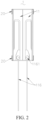
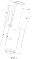
- a tubular heating member 1 in a first embodiment of the present invention may include a heating main body 10 and at least one annular hoop 20 sleeved outside the heating main body 10.
- the heating main body 10 may be a circular tubular body, and may be formed by splicing two semi-circular tubular heating units 11 in the circumferential direction. After the two heating units 11 are spliced into a circular tube in the circumferential direction, the tube is fixed by using the annular hoop 20. In another embodiment, the heating main body 10 may alternatively have another shape such as an oval tubular shape, a square tubular shape, or a polygonal tubular shape. The heating main body 10 may alternatively be formed by splicing two or more heating units 11 in the circumferential direction.
- Each heating unit 11 includes a substrate tube 111 and a composite film disposed on the substrate tube 111.
- the composite film may be a physical vapor deposition composite film (PVD composite film) deposited on the inner surface of the substrate tube 111, and may include a reflective layer 112 disposed inside the substrate tube 111, an insulating layer 113 disposed inside the reflective layer 112, an electric heating layer 114 disposed inside the insulating layer 113, and an infrared radiation layer 115 disposed inside the electric heating layer 114.
- PVD composite film physical vapor deposition composite film
- the electric heating layer 114 and the infrared radiation layer 115 are disposed inside the substrate tube 111, so that the radiation heating ratio can be greatly increased, and heating efficiency of the heating member can be improved.
- the inner wall heating mode can also reduce the temperature of the outer wall of the heating member and simplify heat insulation parts.
- the substrate tube 111 may be molded by injection or extrusion, so that production efficiency is high.
- the substrate tube 111 may be made of a porous high-thermal-resistance ceramic such as porous diatomaceous earth, or high-temperature-resistant glass, and has functions of heat insulation and insulating.
- the thickness of the substrate tube 111 may be between 0.6 mm and 3 mm, and the cross section of the substrate tube 111 is semi-circular arc shaped, and the cross section shape is convenient for extrusion molding.
- the reflective layer 112 may be deposited on the inner surface of the substrate tube 111 by means of pad printing or PVD, and may be made of, for example, a SnO 2 -based, In 2 O 3 -based, ZnO-based, Ag-based, Al-based metal oxide slurry or powder, or a composite doping material thereof having a high reflectance.
- the thickness of the reflective layer 112 may be between 5 ⁇ m and 200 ⁇ m, and preferably between 5 ⁇ m and 30 ⁇ m.
- the insulating layer 113 may be deposited on the reflective layer 112 through screen printing or PVD, and may be made of a non-conductive slurry or powder such as ZrO 2 , SiO 2 , or Al 2 O 3 .
- the thickness of the insulating layer 113 may be between 5 ⁇ m and 40 ⁇ m, preferably between 5 ⁇ m and 20 ⁇ m.
- the insulating layer 113 is disposed between the reflective layer 112 and the electric heating layer 114, so as to insulate the reflective layer 112 from the electric heating layer 114.
- the electric heating layer 114 may be deposited on the insulating layer 113 through screen printing or PVD, and the thickness of the electric heating layer 114 may be between 5 ⁇ m and 100 ⁇ m, preferably between 5 ⁇ m and 50 ⁇ m.
- the electric heating layer 114 may include a conductive line 1141 and a heating film 1142.
- the conductive line 1141 is mainly configured to form an appropriate conductive trace pattern to allocate a heating area according to a requirement.
- the heating film 1142 is mainly configured to heat up after power-on.
- the conductive line 1141 and the heating film 1142 may be made of different materials.
- the conductive line 1141 may be made of a material with a relatively small resistivity and less heat, and the heating film 1142 may be made of a material with a relatively large resistivity.
- the infrared radiation layer 115 may be deposited on the electric heating layer 114 through screen printing or PVD, and may be made of at least one of Fe 2 O 3 , MnO 2 , C O2 O 3 , ZrO 2 , SiO 2 , SiC, TiO 2 , Al 2 O 3 , CeO 2 , La 2 O 3 , MgO, TiC, CrC, TiCN, cordierite, and perovskite.
- the thickness of the infrared radiation layer 115 may be between 5 ⁇ m and 200 ⁇ m, preferably between 5 ⁇ m and 50 ⁇ m.
- the annular hoop 20 may be made of a material such as porous high-thermal-resistance ceramic such as porous diatomaceous earth or high-temperature-resistant glass, and may be integrally sintered with the heating main body 10.
- the sintering temperature may be between 600 degrees Celsius and 1600 degrees Celsius.
- each heating unit 11 may further include two electrode leads 116 electrically connected to the electric heating layer 114, and configured to be electrically connected to a positive electrode and a negative electrode of a battery.
- the two electrode leads 116 may be led out from the inner surface of the heating unit 11, and conductive pads 1161 of the electrode leads 116 may be deposited on the inner surface of the heating unit 11 and directly welded.
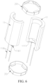
- FIGS. 5-6 show a tubular heating member 1 in a second embodiment of the present invention.
- the two electrode leads 116 of the heating unit 11 in this embodiment may be led out from one end surface of the heating unit 11. It may be understood that in other embodiments, alternatively, the two electrode leads 116 may be respectively led out from two end surfaces of the heating unit 11.
- the conductive pad 1161 of the electrode lead 116 may be deposited on the end surface of the heating unit 11 and directly welded.
- Fillets 1111 are formed on the inner surfaces respectively at the two ends of the heating unit 11. Fillet transition can ensure uniform deposition thickness, and ensure reliable connection of an end surface weld.
- the electric heating layer 114 must be continuously deposited on the end surface of the heating unit 11 to ensure reliable end surface wire bonding.
- the thickness of the substrate tube 111 should be able to put down the pad, and generally is not less than 1.5 mm.
- FIGS. 7-9 show a tubular heating member 1 in a third embodiment of the present invention.
- the tubular heating member 1 may include a heating main body 10, two conductive heat insulating tubes 30 respectively disposed at two axial ends of the heating main body 10, a heat insulating sleeve 50 sleeved outside the heating main body 10 and the two conductive heat insulating tubes 30, and two electrode plates 40 respectively disposed at two ends of the two conductive heat insulating tubes 30.
- the heating main body 10 may be in a cylindrical shape, and may be formed by splicing at least two (three in this embodiment) short cylindrical heating units 11 along the axial direction.
- the heating unit 11 has a low aspect ratio, and an excessively long length of the heating unit 11 is unfavorable for controlling uniformity of PVD deposition thickness. If the length of the heating unit 11 is excessively short, the quantity of assembly sections increases, which is unfavorable for production.
- the axial length of the heating unit 11 may be between 4 mm and 6 mm, so that a reflective layer, an insulating layer, an electric heating layer, and an infrared radiation layer are successively deposited on the inner surface of the substrate tube 111 by means of PVD.
- the reflective layer may be plated on the outer surface of the substrate tube 111, or may be disposed on the inner surface of the heat insulating sleeve 50.
- the heating unit 11 and the conductive heat insulating tube 30 are separately manufactured, the manufacturing process of a single short tube is relatively simplified, and an internal heating part and conductive part may be manufactured into an integral thin film.
- the end surface of the heating unit 11 needs to be polished and flattened, and fillets are formed on the inner surfaces at the two ends of the heating unit 11.
- the electric heating layer must be continuously deposited on two end surfaces of the heating unit 11, and two adjacent heating units 11 are connected in series by using the electric heating layer on the two end surfaces.
- the conductive heat insulating tube 30 is disposed at two ends of the heating main body 10, and is configured to conduct the heating unit 11 and the electrode plate 40 and perform heat insulation.
- the conductive heat insulating tube 30 may include a main substrate and a conductive layer disposed on the main substrate.
- the main substrate may be made of a porous high-thermal-resistance ceramic such as porous diatomaceous earth, high-temperature-resistant glass, or the like.
- the conductive layer may be deposited on the inner surface and two end surfaces of the main substrate through PVD, and is configured to connect the electric heating layer of the heating main body 10 and the electrode plate 40 in series.
- the conductive heat insulating tube 30 has a relatively low aspect ratio, so that a conductive layer is deposited on the inner surface of the main substrate through PVD.
- the heat insulating sleeve 50 is disposed outside the heating main body 10 and the two conductive heat insulating tubes 30, and has a heat insulating function.
- the heat insulating sleeve 50 may be made of a material such as a porous high-thermal-resistance ceramic such as porous diatomaceous earth or high-temperature-resistant glass.
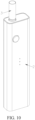
- the present invention further provides an aerosol-generating apparatus.
- the aerosol-generating apparatus may be substantially in a square column shape and includes a housing 2, a tubular heating member 1 disposed in the housing 2, and a battery disposed in the housing 2 and electrically connected to the tubular heating member 1.
- An aerosol-generating substrate 3 may be inserted into the housing 2 from the top of the housing 2 and protrude into the tubular heating member 1. After being energized and heated, the tubular heating member 1 bakes and heats the aerosol-generating substrate 3 to form an aerosol for a user to inhale.
- the aerosol-generating substrate 3 may be a cigarette. It may be understood that the aerosol-generating apparatus is not limited to being in a square columnar shape, or may be in another shape such as a columnar shape.
- the tubular heating member 1 in the present invention has at least the following advantages:
Landscapes
- Resistance Heating (AREA)
Applications Claiming Priority (2)
| Application Number | Priority Date | Filing Date | Title |
|---|---|---|---|
| CN202120298672.0U CN216875034U (zh) | 2021-02-02 | 2021-02-02 | 管状发热体及气溶胶产生装置 |
| PCT/CN2021/133701 WO2022166336A1 (zh) | 2021-02-02 | 2021-11-26 | 管状发热体及气溶胶产生装置 |
Publications (2)
| Publication Number | Publication Date |
|---|---|
| EP4282292A1 true EP4282292A1 (de) | 2023-11-29 |
| EP4282292A4 EP4282292A4 (de) | 2024-08-07 |
Family
ID=82178651
Family Applications (1)
| Application Number | Title | Priority Date | Filing Date |
|---|---|---|---|
| EP21924331.8A Pending EP4282292A4 (de) | 2021-02-02 | 2021-11-26 | Rohrförmiger heizkörper und aerosolerzeugungsvorrichtung |
Country Status (4)
| Country | Link |
|---|---|
| US (1) | US20240016214A1 (de) |
| EP (1) | EP4282292A4 (de) |
| CN (1) | CN216875034U (de) |
| WO (1) | WO2022166336A1 (de) |
Cited By (1)
| Publication number | Priority date | Publication date | Assignee | Title |
|---|---|---|---|---|
| WO2025098936A1 (de) * | 2023-11-06 | 2025-05-15 | Innovative Sensor Technology Ist Ag | Verfahren zur herstellung einer aufnahmevorrichtung für eine aerosolerzeugungsvorrichtung, aufnahmevorrichtung und aerosolerzeugungsvorrichtung |
Families Citing this family (6)
| Publication number | Priority date | Publication date | Assignee | Title |
|---|---|---|---|---|
| CN213848764U (zh) * | 2020-08-03 | 2021-08-03 | 深圳市合元科技有限公司 | 加热器以及包括该加热器的烟具 |
| CN114246369A (zh) * | 2020-09-23 | 2022-03-29 | 深圳市合元科技有限公司 | 气溶胶生成装置以及红外加热器 |
| CN115088880A (zh) * | 2022-07-29 | 2022-09-23 | 深圳市赛尔美电子科技有限公司 | 液体雾化方法及雾化装置 |
| CN115644517A (zh) * | 2022-10-26 | 2023-01-31 | 深圳市泽华永盛技术有限公司 | 组装式发热体及其制备方法和烟草加热器 |
| CN219373827U (zh) * | 2022-11-17 | 2023-07-21 | 思摩尔国际控股有限公司 | 气溶胶产生装置及其发热结构 |
| CN219982157U (zh) * | 2023-05-23 | 2023-11-10 | 深圳市合元科技有限公司 | 气雾生成装置及用于气雾生成装置的加热器 |
Family Cites Families (12)
| Publication number | Priority date | Publication date | Assignee | Title |
|---|---|---|---|---|
| NZ718007A (en) * | 2013-10-29 | 2017-06-30 | British American Tobacco Investments Ltd | Apparatus for heating smokable material |
| WO2016123738A1 (zh) * | 2015-02-02 | 2016-08-11 | 深圳麦克韦尔股份有限公司 | 卷烟加热器及其加热组件 |
| CN104770895B (zh) * | 2015-03-13 | 2017-08-08 | 云南中烟工业有限责任公司 | 用于烟制品的加热装置以及烟雾发生器 |
| WO2016179828A1 (zh) * | 2015-05-14 | 2016-11-17 | 惠州市吉瑞科技有限公司深圳分公司 | 一种电子烟 |
| KR102515109B1 (ko) * | 2017-07-21 | 2023-03-28 | 주식회사 아모그린텍 | 궐련형 전자담배용 원통형 발열히터 및 이를 포함하는 궐련형 전자담배 |
| CN110313639A (zh) * | 2018-03-30 | 2019-10-11 | 湖南中烟工业有限责任公司 | 分区加热式发热体及其应用的低温烟具 |
| CN110101124A (zh) * | 2019-06-10 | 2019-08-09 | 东莞市麦斯莫科电子科技有限公司 | 模块化多温度段发热装置 |
| US20220386698A1 (en) * | 2019-07-04 | 2022-12-08 | Philip Morris Products S.A. | Inductive heating arrangement with segmented inductive heating element |
| CN110384264A (zh) * | 2019-07-15 | 2019-10-29 | 深圳市合元科技有限公司 | 加热器及低温加热烟具 |
| CN211910516U (zh) * | 2019-12-23 | 2020-11-13 | 深圳市合元科技有限公司 | 气雾生成装置和用于气雾生成装置的红外发射器 |
| CN211910554U (zh) * | 2020-01-17 | 2020-11-13 | 深圳市合元科技有限公司 | 烘烤烟具 |
| CN112205682B (zh) * | 2020-11-07 | 2025-12-02 | 松湖神健科技(东莞)有限公司 | 一种纳米碳纤维膜快速升温电子烟加热管 |
-
2021
- 2021-02-02 CN CN202120298672.0U patent/CN216875034U/zh active Active
- 2021-11-26 WO PCT/CN2021/133701 patent/WO2022166336A1/zh not_active Ceased
- 2021-11-26 EP EP21924331.8A patent/EP4282292A4/de active Pending
-
2023
- 2023-08-01 US US18/363,111 patent/US20240016214A1/en active Pending
Cited By (1)
| Publication number | Priority date | Publication date | Assignee | Title |
|---|---|---|---|---|
| WO2025098936A1 (de) * | 2023-11-06 | 2025-05-15 | Innovative Sensor Technology Ist Ag | Verfahren zur herstellung einer aufnahmevorrichtung für eine aerosolerzeugungsvorrichtung, aufnahmevorrichtung und aerosolerzeugungsvorrichtung |
Also Published As
| Publication number | Publication date |
|---|---|
| US20240016214A1 (en) | 2024-01-18 |
| WO2022166336A1 (zh) | 2022-08-11 |
| EP4282292A4 (de) | 2024-08-07 |
| CN216875034U (zh) | 2022-07-05 |
Similar Documents
| Publication | Publication Date | Title |
|---|---|---|
| EP4282292A1 (de) | Rohrförmiger heizkörper und aerosolerzeugungsvorrichtung | |
| EP3815559A1 (de) | Rauchgehärtete tabakvorrichtung und heizanordnung dafür | |
| WO2021139491A1 (zh) | 气溶胶产生装置及其发热组件 | |
| KR20220080724A (ko) | 에어러졸 발생장치 및 그 가열 어셈블리 | |
| US20230330892A1 (en) | Heating tube, manufacturing method thereof, and aerosol generating device | |
| CN109123806B (zh) | 烘烤烟具 | |
| CN110200331A (zh) | 一种电子烟加热器 | |
| EP4353098A1 (de) | Aerosolerzeugungsvorrichtung und heizanordnung dafür | |
| CN114587023A (zh) | 气溶胶形成装置及其加热组件 | |
| CN113712277A (zh) | 烘烤烟具及其加热组件 | |
| CN114246373B (zh) | 发热组件及气溶胶形成装置 | |
| WO2023109532A1 (zh) | 加热器以及包括该加热器的烟具 | |
| CN111990702A (zh) | 一种感应加热装置 | |
| CN212629868U (zh) | 一种感应加热装置 | |
| CN218457298U (zh) | 气溶胶产生装置及其发热组件 | |
| WO2024007613A1 (zh) | 气溶胶产生装置及其发热组件 | |
| CN211065053U (zh) | 一种电子烟加热器 | |
| US20240041114A1 (en) | Aerosol-forming apparatus and heating assembly | |
| CN218605115U (zh) | 气溶胶产生装置及其发热组件 | |
| CN210275912U (zh) | 一种加热元件及雾化设备 | |
| CN218245675U (zh) | 气溶胶产生装置及其发热组件 | |
| CN115486572B (zh) | 一种辐射与传导双加热的加热不燃烧烟具 | |
| CN111954320A (zh) | 金属加热体的制造方法 | |
| CN207854205U (zh) | 一种电加热基板元件以及具有该电加热元件的加热装置 | |
| CN110677936A (zh) | 一种陶瓷加热体 |
Legal Events
| Date | Code | Title | Description |
|---|---|---|---|
| STAA | Information on the status of an ep patent application or granted ep patent |
Free format text: STATUS: THE INTERNATIONAL PUBLICATION HAS BEEN MADE |
|
| PUAI | Public reference made under article 153(3) epc to a published international application that has entered the european phase |
Free format text: ORIGINAL CODE: 0009012 |
|
| STAA | Information on the status of an ep patent application or granted ep patent |
Free format text: STATUS: REQUEST FOR EXAMINATION WAS MADE |
|
| 17P | Request for examination filed |
Effective date: 20230823 |
|
| AK | Designated contracting states |
Kind code of ref document: A1 Designated state(s): AL AT BE BG CH CY CZ DE DK EE ES FI FR GB GR HR HU IE IS IT LI LT LU LV MC MK MT NL NO PL PT RO RS SE SI SK SM TR |
|
| DAV | Request for validation of the european patent (deleted) | ||
| DAX | Request for extension of the european patent (deleted) | ||
| A4 | Supplementary search report drawn up and despatched |
Effective date: 20240710 |
|
| RIC1 | Information provided on ipc code assigned before grant |
Ipc: H05B 3/46 20060101ALI20240704BHEP Ipc: A24F 47/00 20200101ALI20240704BHEP Ipc: A24F 40/40 20200101ALI20240704BHEP Ipc: A24F 40/46 20200101AFI20240704BHEP |
|
| RAP3 | Party data changed (applicant data changed or rights of an application transferred) |
Owner name: SHENZHEN SMOORE TECHNOLOGY LIMITED |
|
| RAP3 | Party data changed (applicant data changed or rights of an application transferred) |
Owner name: SHENZHEN SMOORE TECHNOLOGY LIMITED |