EP4282017B1 - Fördervorrichtung für medien - Google Patents
Fördervorrichtung für medien Download PDFInfo
- Publication number
- EP4282017B1 EP4282017B1 EP22701578.1A EP22701578A EP4282017B1 EP 4282017 B1 EP4282017 B1 EP 4282017B1 EP 22701578 A EP22701578 A EP 22701578A EP 4282017 B1 EP4282017 B1 EP 4282017B1
- Authority
- EP
- European Patent Office
- Prior art keywords
- conveying device
- fuel cell
- conveying
- cooling medium
- drive machine
- Prior art date
- Legal status (The legal status is an assumption and is not a legal conclusion. Google has not performed a legal analysis and makes no representation as to the accuracy of the status listed.)
- Active
Links
Images
Classifications
-
- H—ELECTRICITY
- H01—ELECTRIC ELEMENTS
- H01M—PROCESSES OR MEANS, e.g. BATTERIES, FOR THE DIRECT CONVERSION OF CHEMICAL ENERGY INTO ELECTRICAL ENERGY
- H01M8/00—Fuel cells; Manufacture thereof
- H01M8/04—Auxiliary arrangements, e.g. for control of pressure or for circulation of fluids
- H01M8/04082—Arrangements for control of reactant parameters, e.g. pressure or concentration
- H01M8/04201—Reactant storage and supply, e.g. means for feeding, pipes
-
- H—ELECTRICITY
- H01—ELECTRIC ELEMENTS
- H01M—PROCESSES OR MEANS, e.g. BATTERIES, FOR THE DIRECT CONVERSION OF CHEMICAL ENERGY INTO ELECTRICAL ENERGY
- H01M8/00—Fuel cells; Manufacture thereof
- H01M8/04—Auxiliary arrangements, e.g. for control of pressure or for circulation of fluids
- H01M8/04007—Auxiliary arrangements, e.g. for control of pressure or for circulation of fluids related to heat exchange
- H01M8/04029—Heat exchange using liquids
-
- H—ELECTRICITY
- H01—ELECTRIC ELEMENTS
- H01M—PROCESSES OR MEANS, e.g. BATTERIES, FOR THE DIRECT CONVERSION OF CHEMICAL ENERGY INTO ELECTRICAL ENERGY
- H01M8/00—Fuel cells; Manufacture thereof
- H01M8/04—Auxiliary arrangements, e.g. for control of pressure or for circulation of fluids
- H01M8/04082—Arrangements for control of reactant parameters, e.g. pressure or concentration
- H01M8/04089—Arrangements for control of reactant parameters, e.g. pressure or concentration of gaseous reactants
- H01M8/04097—Arrangements for control of reactant parameters, e.g. pressure or concentration of gaseous reactants with recycling of the reactants
-
- H—ELECTRICITY
- H01—ELECTRIC ELEMENTS
- H01M—PROCESSES OR MEANS, e.g. BATTERIES, FOR THE DIRECT CONVERSION OF CHEMICAL ENERGY INTO ELECTRICAL ENERGY
- H01M8/00—Fuel cells; Manufacture thereof
- H01M8/04—Auxiliary arrangements, e.g. for control of pressure or for circulation of fluids
- H01M8/04082—Arrangements for control of reactant parameters, e.g. pressure or concentration
- H01M8/04089—Arrangements for control of reactant parameters, e.g. pressure or concentration of gaseous reactants
- H01M8/04111—Arrangements for control of reactant parameters, e.g. pressure or concentration of gaseous reactants using a compressor turbine assembly
-
- H—ELECTRICITY
- H01—ELECTRIC ELEMENTS
- H01M—PROCESSES OR MEANS, e.g. BATTERIES, FOR THE DIRECT CONVERSION OF CHEMICAL ENERGY INTO ELECTRICAL ENERGY
- H01M2250/00—Fuel cells for particular applications; Specific features of fuel cell system
- H01M2250/20—Fuel cells in motive systems, e.g. vehicle, ship, plane
-
- Y—GENERAL TAGGING OF NEW TECHNOLOGICAL DEVELOPMENTS; GENERAL TAGGING OF CROSS-SECTIONAL TECHNOLOGIES SPANNING OVER SEVERAL SECTIONS OF THE IPC; TECHNICAL SUBJECTS COVERED BY FORMER USPC CROSS-REFERENCE ART COLLECTIONS [XRACs] AND DIGESTS
- Y02—TECHNOLOGIES OR APPLICATIONS FOR MITIGATION OR ADAPTATION AGAINST CLIMATE CHANGE
- Y02E—REDUCTION OF GREENHOUSE GAS [GHG] EMISSIONS, RELATED TO ENERGY GENERATION, TRANSMISSION OR DISTRIBUTION
- Y02E60/00—Enabling technologies; Technologies with a potential or indirect contribution to GHG emissions mitigation
- Y02E60/30—Hydrogen technology
- Y02E60/50—Fuel cells
-
- Y—GENERAL TAGGING OF NEW TECHNOLOGICAL DEVELOPMENTS; GENERAL TAGGING OF CROSS-SECTIONAL TECHNOLOGIES SPANNING OVER SEVERAL SECTIONS OF THE IPC; TECHNICAL SUBJECTS COVERED BY FORMER USPC CROSS-REFERENCE ART COLLECTIONS [XRACs] AND DIGESTS
- Y02—TECHNOLOGIES OR APPLICATIONS FOR MITIGATION OR ADAPTATION AGAINST CLIMATE CHANGE
- Y02T—CLIMATE CHANGE MITIGATION TECHNOLOGIES RELATED TO TRANSPORTATION
- Y02T90/00—Enabling technologies or technologies with a potential or indirect contribution to GHG emissions mitigation
- Y02T90/40—Application of hydrogen technology to transportation, e.g. using fuel cells
Definitions
- the invention relates to a conveying device for media in a fuel cell system according to the type defined in more detail in the preamble of claim 1.
- the invention also relates to a fuel cell system with such a conveying device and to a vehicle with such a fuel cell system.
- Fuel cell systems for example for use in providing electrical drive power in at least partially electrically powered vehicles, are known from the state of the art.
- air must be supplied as an oxygen supplier and, on the other hand, a cooling system is necessary in which a typically liquid cooling medium is circulated to dissipate waste heat.
- many fuel cells have a so-called anode circuit.
- a recirculation blower is often provided to compensate for pressure losses, either alone or in support of a gas jet pump.
- both the coolant pump and an air conveying device, such as a flow compressor, and a recirculation conveying device, such as a recirculation blower are typically each equipped with their own drive, typically an electric motor drive. On the one hand, this requires a lot of installation space and, on the other hand, the need for a large number of electrical supply lines to the individual components.
- the DE 10 2004 037 141 A1 therefore describes a fuel cell system with media conveying units, in which a common drive is available for several units.
- the necessary speeds and conveying capacities are adjusted using appropriate speed increase and/or reduction devices, i.e. gears, and if necessary the individual units can be switched on and off for propulsion by the one drive unit.
- the object of the present invention is to provide an improved conveying device for media in a fuel cell system.
- this object is achieved by a conveying device having the features in claim 1. Furthermore, a fuel cell system with such a conveying device solves the problem. A vehicle with a fuel cell system and such a conveying device can also solve the problem.
- the conveying device uses, similarly to the prior art mentioned at the beginning, a common drive machine for a cooling medium pump, a
- Conveying device for air and a conveying device for anode exhaust gas The drive machine is directly connected to a rotor shaft of the drive machine with the cooling medium pump. Any lubricants and the like that are required in the area of the drive machine, typically an electric drive machine, are relatively uncritical here, so that the direct connection with a common shaft is advantageous here.
- either the cooling medium pump or the drive machine is now magnetically coupled to one of the conveying devices and the drive machine or the coupled conveying device is then coupled to the other conveying device with another magnetic coupling.
- this has the decisive advantage that only a single drive machine is required, preferably an electric drive machine, which can, however, be supported by a turbine if necessary, as is the case with the so-called electric turbocharger, which is generally known and common in fuel cell systems.
- This drive machine can in turn be coupled directly to the cooling medium pump with its driven shaft, for example the rotor shaft of the electric drive motor, and drive it directly.
- the two conveying devices for the air and the anode exhaust gas are then coupled via magnetic couplings.
- the magnetic coupling of the air conveyor on the one hand and the conveyor for recirculating the anode exhaust gas on the other hand has the decisive advantage that the structure can be sealed very easily and efficiently with the appropriate media. This is a decisive advantage, especially for the anode exhaust gas, which contains hydrogen, in order to prevent the escape of To efficiently prevent hydrogen from escaping into the environment. This is essential for safety reasons.
- a gear for speed adjustment is provided in the area of the cooling medium pump and/or one of the conveying devices for at least one of the conveying devices.
- the gear is arranged on the motor side or in the area of the cooling medium pump and the already translated speed is then transmitted via the magnetic coupling to the compressor wheel and/or the fan wheel of the respective conveying device.
- This structure minimizes contamination with corresponding lubricants, which are provided, for example, in the area of the gear.
- simple unlubricated gear elements can also be used, for example in the area of the recirculation fan, so that the gear could also be arranged between the magnetic coupling and the recirculation fan itself.
- Such a conveying device is particularly suitable for use in fuel cell systems which have at least one cooling medium pump, at least one conveying device for the air and at least one conveying device for recirculating anode exhaust gas.
- the conveying device can be used advantageously there. This applies in principle both to stationary fuel cell systems and to vehicles which are supplied with at least part of their electrical drive power by at least one of these fuel cell systems.
- a fuel cell system 1 can be seen which is to be used in a very schematically indicated vehicle 2 to provide at least part of the electrical drive power.
- vehicle 2 to provide at least part of the electrical drive power.
- the fuel cell stack 3 shown schematically here comprises a cathode chamber 4, an anode chamber 5 and an exemplary cooling heat exchanger 6 inside the fuel cell stack 3.
- the cathode chamber 4 is separated from the anode chamber 5 by a proton-conducting membrane 7.
- this structure is implemented as a stack of individual cells.
- a common cathode chamber 4 and a common anode chamber 5 as well as a common cooling heat exchanger 6 are shown schematically purely as an example.
- Hydrogen is supplied to the cathode chamber 4 from a compressed gas reservoir 10 via a pressure control and metering valve 11. Unused hydrogen is returned to a so-called anode circuit 12 via a recirculation line 13. Pressure losses are compensated for by a conveyor device 14 for the recirculated anode exhaust gas.
- Product water generated in the area of the anode chamber 5 is separated via a water separator 15. This is discharged via a valve 16 together with inert gases accumulating in the anode circuit 12, for example from time to time or depending on the hydrogen concentration in the anode circuit 12.
- the cooling heat exchanger 6 of the fuel cell stack 3 is part of a cooling circuit 28 in which a liquid cooling medium is circulated via a cooling medium pump 17.
- the waste heat is released into the environment of the vehicle 2 via a cooling heat exchanger, colloquially also referred to as a cooler.
- the cooling circuit 28, which is shown in a very simplified manner, also has a bypass line 19 for bypassing the cooling heat exchanger 18, so that the cooling performance can be controlled with a valve 20 controlling this bypass line and the speed of the cooling medium pump 17.
- the cooling medium pump 17 and the two conveying devices 8, 14 are now to be driven by a common drive machine 21.
- this common drive machine 21 is indicated.
- This drive machine 21 can, for example, be an electric drive machine. It can also be mechanically or electrically coupled to the optimal exhaust air turbine mentioned above in order to realize a drive that is as energy-efficient as possible.
- the drive machine 21 is coupled directly to the cooling medium pump 17 via a shaft 22.
- the cooling medium pump 17 itself or its pump wheel is then coupled to the conveying device 8 for the air via a magnetic coupling 23 with a drive side 24 and an output side 25.
- An optional gear 26 shown cross-hatched can also be provided between the output side 25 of the magnetic coupling 23 and the conveying device 8.
- the conveying device 8 for the air is in turn coupled to a drive side 24 and an output side 25 to the conveying device 14 for the returned anode exhaust gas via a further magnetic coupling 23.
- a further gear 27 can be provided between the output side 25 of the second magnetic coupling 23 and the conveyor device 14 or its impeller.
- the primary entry of lubricants occurs in the area where the shaft 22 directly connects the drive motor 21 and the cooling medium pump 17. This entry is typically harmless for the cooling medium.
- the entry of lubricants into the air and especially into the recirculated exhaust gas is critical, as this could reach the anode chamber 5 or the cathode chamber 4 and adversely affect the electrochemical properties of the fuel cell stack 3. For this reason, a A relatively good and easily sealed decoupling of these conveyor devices 8, 14 from the drive machine 21 is possible.
- the optional gears 26, 27 can aggravate the situation again, but often no or only minimally lubricated gears are necessary in this area, so that this remains relatively uncritical.
- the additional conveyor device 14 is now not connected to the compressor wheel of the conveyor device 8, but is arranged on the other side of the drive motor 21.
- the optional gear 27 is arranged on the motor side and only then does the magnetic coupling 23 follow, so that here too, the entry of possible contamination from the electric drive machine 21 and the optional gear into the area of the blower wheel of the conveyor device 14 can be prevented.
Landscapes
- Life Sciences & Earth Sciences (AREA)
- Sustainable Development (AREA)
- Engineering & Computer Science (AREA)
- Manufacturing & Machinery (AREA)
- Sustainable Energy (AREA)
- Chemical & Material Sciences (AREA)
- Chemical Kinetics & Catalysis (AREA)
- Electrochemistry (AREA)
- General Chemical & Material Sciences (AREA)
- Fuel Cell (AREA)
- Electric Propulsion And Braking For Vehicles (AREA)
Description
- Die Erfindung betrifft eine Fördervorrichtung für Medien in einem Brennstoffzellensystem nach der im Oberbegriff von Anspruch 1 näher definierten Art. Außerdem betrifft die Erfindung ein Brennstoffzellensystem mit einer solchen Fördervorrichtung sowie ein Fahrzeug mit einem solchen Brennstoffzellensystem.
- Brennstoffzellensysteme, beispielsweise für den Einsatz zur Bereitstellung von elektrischer Antriebsleistung in zumindest teilweise elektrisch angetriebenen Fahrzeugen, sind soweit aus dem Stand der Technik bekannt. Bei Brennstoffzellensysteme ist es so, dass einerseits Luft als Sauerstofflieferant gefördert werden muss und andererseits eine Kühlanlage notwendig ist, in welcher ein typischerweise flüssiges Kühlmedium zur Abfuhr von Abwärme umgewälzt wird. Darüber hinaus ist es so, dass in vielen Brennstoffzellen ein sogenannter Anodenkreislauf vorhanden ist. Häufig wird zum Ausgleich von Druckverlusten alleine oder unterstützend zu einer Gasstrahlpumpe ein Rezirkulationsgebläse vorgesehen. In der Praxis ist es nun so, dass typischerweise sowohl die Kühlmittelpumpe als auch eine Luftfördereinrichtung, wie beispielsweise ein Strömungsverdichter, als auch eine Rezirkulationsfördereinrichtung, wie beispielsweise ein Rezirkulationsgebläse jeweils mit einem eigenen Antrieb, typischerweise einem elektromotorischen Antrieb, ausgestattet sind. Dies verursacht einerseits einen hohen Bedarf an Bauraum und andererseits die Notwendigkeit einer Vielzahl von elektrischen Zuleitungen zu den einzelnen Komponenten.
- Die
DE 10 2004 037 141 A1 beschreibt deshalb ein Brennstoffzellensystem mit Aggregaten zur Medienförderung, bei welchen ein gemeinsamer Antrieb für mehrere Aggregate vorhanden ist. Über entsprechende Drehzahlüber- und/oder Untersetzungsvorrichtungen, also Getrieben, werden dabei die notwendigen Drehzahlen und Förderleistungen angepasst sowie gegebenenfalls ein Zuschalten und Abschalten der einzelnen Aggregate zum Antrieb durch das eine Antriebsaggregat vorgenommen. - In der Praxis ist dieser Aufbau relativ kritisch zu bewerten, da durch die benötigten Getriebe, ähnlich wie durch die direkte Anbindung an die Antriebsmotoren gemäß dem zuvor genannten allgemeinen Stand der Technik, häufig Öle in den Bereich der geförderten Luft und/oder des umgewälzten Anodenabgases eingebracht werden. Diese sind für die Brennstoffzelle nachteilig und fördern eine Degradation der elektrochemisch aktiven Komponenten in der Brennstoffzelle, sodass es zu Nachteilen hinsichtlich der zu erwartenden Lebensdauer der Brennstoffzelle kommen kann.
- Zum weiteren Stand der Technik kann außerdem auf die
DE 10 2004 044 068 A1 hingewiesen werden. Diese Schrift beschreibt einen gemeinsamen Antrieb für zwei Fördereinrichtungen für die Luft zu einer Brennstoffzelle einerseits und die Rezirkulation von Anodenabgas andererseits. Um ein Vermischen dieser Stoffe zu verhindern, sind diese an den gemeinsamen Antriebsmotor hermetisch abgedichtet angebunden, indem der Aufbau jeweils in Form sogenannter Spaltrohrmotoren realisiert ist. - Zum weiteren Stand der Technik kann auf die
DE 10 2012 008 494 A1 hingewiesen werden, welche zwei Kühlmedienpumpen mit einem gemeinsamen elektromotorischen Antrieb zeigt. Außerdem kann noch auf dieWO 2010/082913 A1 hingewiesen werden. Diese zeigt mehrere in einem Motorgehäuse zusammengefasste elektromotorische Antriebe, welche mit den jeweils angetriebenen Förderaggregaten magnetisch gekoppelt sind. Weiterhin offenbart das DokumentWO 00/54353 A1 CN 205 985 199 U ein Brennstoffzellensystem mit einer integrierten Antriebsstruktur. - Die Aufgabe der hier vorliegenden Erfindung besteht nun darin, eine verbesserte Fördervorrichtung für Medien in einem Brennstoffzellensystem anzugeben.
- Erfindungsgemäß wird diese Aufgabe durch eine Fördervorrichtung mit den Merkmalen im Anspruch 1 gelöst. Ferner löst ein Brennstoffzellensystem mit einer solchen Fördervorrichtung die Aufgabe. Auch ein Fahrzeug mit einem Brennstoffzellensystem und einer solchen Fördervorrichtung kann die Aufgabe lösen.
- Weitere vorteilhafte Ausgestaltungen der Fördervorrichtung ergeben sich dabei außerdem aus den vom Hauptanspruch abhängigen Unteransprüchen.
- Die erfindungsgemäße Fördervorrichtung nutzt ähnlich wie der eingangs genannte Stand der Technik eine gemeinsame Antriebsmaschine für eine Kühlmedienpumpe, eine
- Fördereinrichtung für Luft und eine Fördereinrichtung für Anodenabgas. Die Antriebsmaschine ist dabei direkt mit einer Rotorwelle der Antriebsmaschine mit der Kühlmedienpumpe verbunden. Eventuelle Schmierstoffe und dergleichen, welche im Bereich der Antriebsmaschine, typischerweise eine elektrische Antriebsmaschine, benötigt werden, sind hier relativ unkritisch, sodass hier die direkte Anbindung mit einer gemeinsamen Welle von Vorteil ist. Neben dieser direkten Kopplung ist nun entweder die Kühlmedienpumpe oder die Antriebsmaschine magnetisch mit einer der Fördereinrichtungen gekoppelt und wiederum die Antriebsmaschine oder die gekoppelte Fördereinrichtung ist dann mit einer weiteren magnetischen Kopplung mit der anderen Fördereinrichtung gekoppelt.
- Dies hat prinzipiell den entscheidenden Vorteil, dass lediglich eine einzige Antriebsmaschine, vorzugsweise eine elektrische Antriebsmaschine, welche gegebenenfalls jedoch von einer Turbine unterstützt werden kann, wie es bei dem sogenannten elektrischen Turbolader, wie er in Brennstoffzellensystemen allgemein bekannt und üblich ist, der Fall ist, benötigt wird. Diese Antriebsmaschine kann nun ihrerseits mit ihrer angetriebenen Welle, beispielsweise der Rotorwelle des elektrischen Antriebsmotors, direkt mit der Kühlmedienpumpe gekoppelt sein und diese unmittelbar antreiben. Über magnetische Kupplungen sind dann die beiden Fördereinrichtungen für die Luft und das Anodenabgas angekoppelt. Diese können beispielsweise hintereinander angekoppelt sein, sodass also die eine der Fördereinrichtungen, beispielsweise Luftfördereinrichtung bzw. ihr Verdichterrad, über eine Magnetkupplung mit der Pumpe gekoppelt ist und ein Gebläserad der Rezirkulationsfördereinrichtung wiederum mit einer magnetischen Kupplung mit der Luftfördereinrichtung gekoppelt ist. Dies hat den entscheidenden Vorteil, dass weder in die Luft noch das rezirkulierte Anodenabgas unerwünschte Stoffe aus dem Bereich der elektrischen Maschine eingetragen werden. Ein vergleichbarer Aufbau ist selbstverständlich auch möglich, wenn eine oder beide der Fördereinrichtungen magnetisch an die Antriebsmaschine angekoppelt sind, und auf der anderen Seite die Kühlmedienpumpe alleine oder die Kühlmedienpumpe und eine der Fördereinrichtungen entsprechend angekoppelt ist.
- Die magnetische Ankopplung der Fördereinrichtung für die Luft einerseits und der Fördereinrichtung zur Rezirkulation des Anodenabgases andererseits haben dabei den entscheidenden Vorteil, dass der Aufbau mit den entsprechenden Medien sehr einfach und effizient abgedichtet werden kann. Insbesondere beim Anodenabgas, welches Wasserstoff enthält, ist dies von entscheidendem Vorteil, um das Austreten von Wasserstoff an die Umgebung effizient zu verhindern. Dies ist aus Sicherheitsgründen unumgänglich.
- Für zumindest eine der Fördereinrichtungen ist dabei gemäß einer vorteilhaften Ausgestaltung der Fördereinrichtung ein Getriebe zur Drehzahlanpassung im Bereich der Kühlmedienpumpe und/oder einer der Fördereinrichtungen vorgesehen. Vorzugsweise ist es dabei so, dass das Getriebe motorseitig oder im Bereich der Kühlmedienpumpe angeordnet ist und die bereits übersetzte Drehzahl dann über die Magnetkupplung auf das Verdichterrad und/oder das Gebläserad der jeweiligen Fördereinrichtung übertragen wird. Dieser Aufbau minimiert die Kontamination mit entsprechenden Schmierstoffen, welche beispielsweise im Bereich des Getriebes vorgesehen sind. Je nach Aufbau der entsprechenden Fördereinrichtung können jedoch auch einfache ungeschmierte Getriebeelemente zum Einsatz kommen, beispielsweise im Bereich des Rezirkulationsgebläses, sodass das Getriebe auch zwischen der magnetischen Kupplung und dem Rezirkulationsgebläse selbst angeordnet sein könnte.
- Wie bereits erwähnt eignet sich eine solche Fördervorrichtung insbesondere für den Einsatz in Brennstoffzellensystemen, welche wenigstens eine Kühlmedienpumpe, wenigstens eine Fördereinrichtung für die Luft und wenigstens eine Fördereinrichtung zur Rezirkulation von Anodenabgas aufweisen. Die Fördervorrichtung kann dort vorteilhaft zum Einsatz kommen. Dies gilt dabei prinzipiell sowohl bei stationären Brennstoffzellensystemen als auch bei Fahrzeugen, welche mit wenigstens einem dieser Brennstoffzellensysteme mit zumindest einem Teil ihrer elektrischen Antriebsleistung versorgt werden.
- Weitere vorteilhafte Ausgestaltungen der erfindungsgemäßen Fördervorrichtung, des Brennstoffzellensystems und des Fahrzeugs ergeben sich auch aus dem Ausführungsbeispiel, welches unter Bezugnahme auf die Figuren nachfolgend näher dargestellt ist.
- Dabei zeigen:
- Fig. 1
- ein schematisch angedeutetes Brennstoffzellensystem zur Nutzung der erfindungsgemäßen Fördervorrichtung;
- Fig. 2
- eine erste mögliche Ausführungsform der erfindungsgemäßen Fördervorrichtung in einer schematischen Darstellung; und
- Fig. 3
- eine weitere alternative Ausführungsform der erfindungsgemäßen Fördervorrichtung in einer schematischen Darstellung.
- In der Darstellung der
Figur 1 ist ein Brennstoffzellensystem 1 zu erkennen, welches in einem sehr stark schematisiert angedeuteten Fahrzeug 2 zur Bereitstellung von zumindest einem Teil der elektrischen Antriebsleistung zum Einsatz kommen soll. Je nach Fahrzeug 2 sind dabei mehrere derartige Brennstoffzellensysteme 1 vorgesehen oder innerhalb des hier gezeigten Brennstoffzellensystems 1 sind einer oder mehrere Brennstoffzellenstapel 3 vorgesehen. Der hier schematisch angedeutete eine Brennstoffzellenstapel 3 umfasst einen Kathodenraum 4, einen Anodenraum 5 sowie einen exemplarisch angedeuteten Kühlwärmetauscher 6 im Inneren des Brennstoffzellenstapels 3. Der Kathodenraum 4 ist dabei durch eine protonenleitende Membran 7 vom Anodenraum 5 getrennt. In der Realität ist dieser Aufbau als Stapel von Einzelzellen realisiert. In der Darstellung ist rein beispielhaft ein gemeinsamer Kathodenraum 4 und ein gemeinsamer Anodenraum 5 sowie ein gemeinsamer Kühlwärmetauscher 6 schematisch angedeutet. - Zur Bereitstellung der elektrischen Leistung durch den Brennstoffzellenstapel 3 wird diesem über eine Fördereinrichtung 8 Luft über eine Zuluftleitung 9 zugeführt. Abluft gelangt über eine Abluftleitung 29 an Sauerstoff abgereichert aus dem Brennstoffzellensystem 1 und dem Fahrzeug 2. In diesem Bereich könnte in an sich bekannter Art und Weise eine Abluftturbine vorgesehen werden, um Druckenergie und Wärmeenergie aus der Abluft zurückzugewinnen. Diese ist soweit aus dem Stand der Technik bekannt und könnte hier ebenfalls vorhanden sein. Auf eine Darstellung ist zur Vereinfachung der
Figur 1 verzichtet worden. - Dem Kathodenraum 4 wird Wasserstoff aus einem Druckgasspeicher 10 über ein Druckregel- und Dosierventil 11 zugeführt. Nicht verbrauchter Wasserstoff wird in einem sogenannten Anodenkreislauf 12 über eine Rezirkulationsleitung 13 zurückgeführt. Druckverluste werden dabei durch eine Fördereinrichtung 14 für das rezirkulierte Anodenabgas ausgeglichen. Über einen Wasserabscheider 15 wird im Bereich des Anodenraums 5 entstehendes Produktwasser abgeschieden. Dieses wird über ein Ventil 16 zusammen mit sich im Anodenkreislauf 12 anreichernden inerten Gasen beispielsweise von Zeit zu Zeit oder in Abhängigkeit der Wasserstoffkonzentration in dem Anodenkreislauf 12 abgelassen.
- Der Kühlwärmetauscher 6 des Brennstoffzellenstapels 3 ist Teil eines Kühlkreislaufs 28, in welchem ein flüssiges Kühlmedium über eine Kühlmedienpumpe 17 umgewälzt wird. Die Abwärme wird über einen Kühlwärmetauscher, umgangssprachlich auch als Kühler bezeichnet, in die Umgebung des Fahrzeugs 2 abgegeben. Der sehr stark vereinfacht dargestellte Kühlkreislauf 28 weist außerdem eine Bypassleitung 19 zur Umgehung des Kühlwärmetauschers 18 auf, sodass mit einem diese Bypassleitung steuernden Ventil 20 sowie der Drehzahl der Kühlmedienpumpe 17 die Kühlleistung gesteuert werden kann.
- All dies ist für den Fachmann soweit bekannt, sodass hierauf nicht weiter eingegangen werden muss.
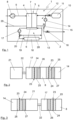
- Die Kühlmedienpumpe 17 und die beiden Fördereinrichtungen 8, 14 sollen nun über eine gemeinsame Antriebsmaschine 21 angetrieben werden. In der Darstellung der
Figur 2 ist diese gemeinsame Antriebsmaschine 21 angedeutet. Es kann sich bei dieser Antriebsmaschine 21 beispielsweise um eine elektrische Antriebsmaschine handeln. Sie kann außerdem mit der oben bereits angesprochenen optimalen Abluftturbine mechanisch oder elektrisch gekoppelt werden, um einen möglichst energieeffizienten Antrieb zu realisieren. Die Antriebsmaschine 21 ist über eine Welle 22 direkt mit der Kühlmedienpumpe 17 gekoppelt. Die Kühlmedienpumpe 17 selbst bzw. ihr Pumpenrad ist dann über eine magnetische Kupplung 23 mit einer Antriebsseite 24 und einer Abtriebsseite 25 mit der Fördereinrichtung 8 für die Luft gekoppelt. Zwischen der Abtriebsseite 25 der magnetischen Kupplung 23 und der Fördereinrichtung 8 kann außerdem ein kreuzschraffiert dargestelltes optionales Getriebe 26 vorgesehen sein. Die Fördereinrichtung 8 für die Luft ist ihrerseits über eine weitere magnetische Kupplung 23 wiederum mit einer Antriebsseite 24 und einer Abtriebsseite 25 mit der Fördereinrichtung 14 für das zurückgeführte Anodenabgas gekoppelt. Auch hier kann ein weiteres Getriebe 27 zwischen der Abtriebsseite 25 der zweiten magnetischen Kupplung 23 und der Fördereinrichtung 14 bzw. ihrem Gebläserad vorgesehen sein. - Der primäre Eintrag von Schmierstoffen geschieht in dem Bereich, in dem die Welle 22 die Antriebsmaschine 21 und die Kühlmedienpumpe 17 direkt verbindet. Für das Kühlmedium ist dieser Eintrag typischerweise unschädlich. Dahingegen ist der Eintrag von Schmierstoffen in die Luft und vor allem in das rezirkulierte Abgas kritisch, da dieses in den Anodenraum 5 oder den Kathodenraum 4 gelangen und dort die elektrochemischen Eigenschaften des Brennstoffzellenstapels 3 nachteilig beeinflussen könnte. Aus diesem Grund kann über die beiden magnetischen Kupplungen 23 eine relativ gute und leicht abzudichtende Abkopplung dieser Fördereinrichtungen 8, 14 von der Antriebsmaschine 21 erfolgen. Die optionalen Getriebe 26, 27 können die Situation zwar wieder verschärfen, häufig sind in diesem Bereich jedoch nicht oder nur minimal geschmierte Getriebe notwendig, sodass dies relativ unkritisch bleibt.
- In der Darstellung der
Figur 3 ist eine alternative Ausführungsvariante dargestellt. Die elektrische Antriebsmaschine 21 ist über ihre Welle 22 wieder mit der Kühlmedienpumpe 17 direkt gekoppelt. Diese ist dann über das optionale Getriebe 26, welches dieses Mal auf der Seite der Kühlmedienpumpe 17 angeordnet ist, mit einer der Magnetkupplungen 23 mit der Fördereinrichtung 8 für die Luft entsprechend gekoppelt. Eventuelle Kontaminationen mit Schmiermittel innerhalb des Getriebes 26 können so von der über die Fördereinrichtung 8 verdichteten Luft ferngehalten werden, da die sehr gut abzudichtende magnetische Kopplung über die magnetische Kupplung 23 zwischen dem Getriebe und dem Verdichterrad der Fördereinrichtung 8 erfolgt. - Die weitere Fördereinrichtung 14 schließt sich nun nicht dem Verdichterrad der Fördereinrichtung 8 an, sondern ist auf der anderen Seite des Antriebsmotors 21 angeordnet. Auch hier ist so, dass motorseitig das optionale Getriebe 27 angeordnet ist und dann erst die magnetische Kupplung 23 folgt, sodass auch hier ein Eintrag eventueller Kontaminationen von der elektrischen Antriebsmaschine 21 und des optionalen Getriebes in den Bereich des Gebläserads der Fördereinrichtung 14 verhindert werden kann.
- Dieser Aufbau mit einer gegenüber der Darstellung in
Figur 2 gedrehten Reihenfolge von optionalem Getriebe 26, 27 und magnetischer Kupplung 23 wäre so selbstverständlich auch in der Darstellung derFigur 2 denkbar. Ebenso wäre es denkbar, bei dem Aufbau gemäßFigur 3 die inFigur 2 gezeigte Reihenfolge einzusetzen. Außerdem wäre es selbstverständlich denkbar, die beiden Fördereinrichtungen 8, 14 gegeneinander zu vertauschen oder beide auf der einen Seite der elektrischen Antriebsmaschine 21 anzubringen und die Kühlmedienpumpe 17 auf der anderen Seite der Antriebsmaschine 21.
Claims (7)
- Fördervorrichtung für Medien in einem Brennstoffzellensystem (1) mit einer Antriebsmaschine (21), über welche über wenigstens eine Kühlmedienpumpe (17) wenigstens eine Fördereinrichtung (8) für Luft und wenigstens eine Fördereinrichtung (14) für rezirkuliertes Anodenabgas angetrieben sind,
dadurch gekennzeichnet, dass
die Antriebsmaschine (21) eine Rotorwelle (22) aufweist, mit welcher die Kühlmedienpumpe (17) direkt gekoppelt ist, wobei die Kühlmedienpumpe (17) oder die Antriebsmaschine (21) magnetisch mit einer der Fördereinrichtungen (8, 14) und die Antriebsmaschine (21) oder die Fördereinrichtung (8, 14) magnetisch mit der anderen Fördereinrichtung (14, 8) gekoppelt ist. - Fördervorrichtung nach Anspruch 1,
dadurch gekennzeichnet, dass
die Fördereinrichtung (8) für die Luft als Strömungsverdichter ausgebildet ist. - Fördervorrichtung nach Anspruch 1 oder 2,
dadurch gekennzeichnet, dass
die Fördereinrichtung (14) zur Rezirkulation von Anodenabgas als Rezirkulationsgebläse ausgebildet ist. - Fördervorrichtung nach Anspruch 1, 2 oder 3,
dadurch gekennzeichnet, dass
im Bereich zumindest einer der Fördereinrichtungen (8, 14) ein Getriebe (26, 27) zur Drehzahlanpassung vorgesehen ist. - Fördervorrichtung nach Anspruch 4,
dadurch gekennzeichnet, dass
das Getriebe (26, 27) auf der der jeweiligen Fördereinrichtung (8, 14) abgewandten Seite der magnetischen Kupplung (23) vorgesehen ist. - Brennstoffzellensystem (1) mit einer Fördervorrichtung nach einem der Ansprüche 1 bis 5.
- Fahrzeug (2) mit wenigstens einem Brennstoffzellensystem (1) nach Anspruch 6.
Applications Claiming Priority (2)
| Application Number | Priority Date | Filing Date | Title |
|---|---|---|---|
| DE102021000306.3A DE102021000306A1 (de) | 2021-01-22 | 2021-01-22 | Fördervorrichtung für Medien |
| PCT/EP2022/051152 WO2022157206A2 (de) | 2021-01-22 | 2022-01-19 | Fördervorrichtung für medien |
Publications (3)
| Publication Number | Publication Date |
|---|---|
| EP4282017A2 EP4282017A2 (de) | 2023-11-29 |
| EP4282017C0 EP4282017C0 (de) | 2024-12-25 |
| EP4282017B1 true EP4282017B1 (de) | 2024-12-25 |
Family
ID=75155700
Family Applications (1)
| Application Number | Title | Priority Date | Filing Date |
|---|---|---|---|
| EP22701578.1A Active EP4282017B1 (de) | 2021-01-22 | 2022-01-19 | Fördervorrichtung für medien |
Country Status (7)
| Country | Link |
|---|---|
| US (1) | US20240072278A1 (de) |
| EP (1) | EP4282017B1 (de) |
| JP (1) | JP7642074B2 (de) |
| KR (1) | KR102876682B1 (de) |
| CN (1) | CN116745943A (de) |
| DE (1) | DE102021000306A1 (de) |
| WO (1) | WO2022157206A2 (de) |
Families Citing this family (1)
| Publication number | Priority date | Publication date | Assignee | Title |
|---|---|---|---|---|
| DE102024116282A1 (de) * | 2024-06-11 | 2025-12-11 | Zf Cv Systems Global Gmbh | Strömungsmaschine für ein wenigstens ein Brennstoffzellensystem mit wenigstens einem Brennstoffzellenstapel aufweisendes Fahrzeug, insbesondere Nutzfahrzeug, Brennstoffzellensystem, Fahrzeug |
Family Cites Families (12)
| Publication number | Priority date | Publication date | Assignee | Title |
|---|---|---|---|---|
| JPS53145132U (de) * | 1977-04-21 | 1978-11-15 | ||
| WO2000054353A1 (de) * | 1999-03-10 | 2000-09-14 | Siemens Aktiengesellschaft | Verfahren zum betreiben einer brennstoffzellenanlage und brennstoffzellenanlage |
| JP2004087147A (ja) * | 2002-08-22 | 2004-03-18 | Aisin Seiki Co Ltd | 改質原料供給装置 |
| DE102004037141A1 (de) | 2004-07-30 | 2006-03-23 | Robert Bosch Gmbh | Zentralantrieb für die Medienversorgung eines Brennstoffzellensystems |
| DE102004044068B4 (de) | 2004-09-11 | 2007-07-26 | Pierburg Gmbh | Vorrichtung zur Sauerstoffversorgung und Anodengasrezirkulation eines Brennstoffzellensystems |
| US7659015B2 (en) * | 2006-01-20 | 2010-02-09 | Airbus Deutschland Gmbh | Combined fuel cell system |
| US9444110B2 (en) | 2009-01-15 | 2016-09-13 | Doosan Fuel Cell America, Inc. | System and method for reducing fuel cell power plant emissions |
| DE102012001604A1 (de) * | 2012-01-26 | 2013-08-01 | Daimler Ag | Anodenkreislauf für ein Brennstoffzellensystem |
| DE102012008494A1 (de) | 2012-04-26 | 2013-10-31 | Daimler Ag | Brennstoffzellensystem |
| JP2016223427A (ja) * | 2015-05-28 | 2016-12-28 | 日産自動車株式会社 | ガス供給システム、燃料電池システム及びガス供給システムの制御方法 |
| JP6465308B2 (ja) * | 2016-02-25 | 2019-02-06 | トヨタ自動車株式会社 | 圧力センサの異常検出方法及び燃料電池システム |
| CN205985199U (zh) * | 2016-08-04 | 2017-02-22 | 上海汽车集团股份有限公司 | 一种燃料电池系统集成化驱动结构 |
-
2021
- 2021-01-22 DE DE102021000306.3A patent/DE102021000306A1/de active Pending
-
2022
- 2022-01-19 EP EP22701578.1A patent/EP4282017B1/de active Active
- 2022-01-19 KR KR1020237026163A patent/KR102876682B1/ko active Active
- 2022-01-19 CN CN202280009357.9A patent/CN116745943A/zh active Pending
- 2022-01-19 WO PCT/EP2022/051152 patent/WO2022157206A2/de not_active Ceased
- 2022-01-19 US US18/261,208 patent/US20240072278A1/en active Pending
- 2022-01-19 JP JP2023540172A patent/JP7642074B2/ja active Active
Also Published As
| Publication number | Publication date |
|---|---|
| EP4282017C0 (de) | 2024-12-25 |
| KR20230128336A (ko) | 2023-09-04 |
| JP7642074B2 (ja) | 2025-03-07 |
| EP4282017A2 (de) | 2023-11-29 |
| JP2024503326A (ja) | 2024-01-25 |
| US20240072278A1 (en) | 2024-02-29 |
| WO2022157206A2 (de) | 2022-07-28 |
| WO2022157206A3 (de) | 2022-09-22 |
| DE102021000306A1 (de) | 2021-04-15 |
| KR102876682B1 (ko) | 2025-10-24 |
| CN116745943A (zh) | 2023-09-12 |
Similar Documents
| Publication | Publication Date | Title |
|---|---|---|
| EP2176911B1 (de) | Verfahren und vorrichtung zum betreiben eines brennstoffzellensystems mit einem in einen brennstoffkreislauf des brennstoffzellensystems angeordneten rezirkulationsgebläse | |
| DE102011087606A1 (de) | Kraftfahrzeugsystemeinrichtung sowie Verfahren zum Betreiben einer Kraftfahrzeugsystemeinrichtung | |
| EP4282018A1 (de) | Brennstoffzellenanlage mit zwei parallelen brennstoffzellensystemen | |
| EP4150688A1 (de) | Luftversorgungsvorrichtung für brennstoffzellensysteme und brennstoffzellensystem | |
| EP4334989B1 (de) | Luftversorgungsvorrichtung, brennstoffzellensystem und fahrzeug | |
| EP4282017B1 (de) | Fördervorrichtung für medien | |
| DE102021207632A1 (de) | Brennstoffzellensystem und Rezirkulationsvorrichtung zur Rezirkulation von Anodenabgas in einem Brennstoffzellensystem | |
| DE102023103755B4 (de) | Ergänzung eines elektrischen Bremswiderstands sowie Alternative zu einem elektrischen Bremswiderstand | |
| DE102015013062A1 (de) | Elektrisches System für ein Brennstoffzellenfahrzeug | |
| DE102009049198A1 (de) | Fahrzeug mit einem Brennstoffzellensystem | |
| DE102021113063A1 (de) | Kühlsystem und Verfahren zum Betreiben eines Kühlsystems | |
| DE102020007640A1 (de) | Anodenkreislauf für eine Brennstoffzelle | |
| DE102020208917A1 (de) | Verfahren zum Betreiben einer rotierenden Arbeitsmaschine, rotierende Arbeitsmaschine sowie Brennstoffzellensystem mit rotierender Arbeitsmaschine | |
| EP4118350B1 (de) | Lageranordnung für eine welle eines turbokompressors | |
| DE102014017806A1 (de) | Brennstoffzellensystem und Klimaanlage | |
| WO2024047116A2 (de) | Strömungsmaschinenanordnung, brennstoffzellensystem und fahrzeug, insbesondere nutzfahrzeug | |
| DE102022125588A1 (de) | Kühlsystem für eine elektrische Traktionsmaschine für ein Kraftfahrzeug | |
| DE102016119444A1 (de) | Kühlereinrichtung für ein Brennstoffzellenfahrzeug | |
| WO2022106194A1 (de) | Gaszuführvorrichtung | |
| EP1641064B1 (de) | Brennstoffzellensystem | |
| DE102024102051A1 (de) | Brennstoffzellensystem und Fahrzeug mit dem Brennstoffzellensystem | |
| EP4325608B1 (de) | Kühlsystem und verfahren zum betreiben eines kühlsystems für wenigstens eine komponente eines brennstoffzellensystems | |
| DE102024116286A1 (de) | Kopplungsanordnung für ein Brennstoffzellensystem für ein Fahrzeug, insbesondere Nutzfahrzeug, Brennstoffzellensystem und Fahrzeug | |
| WO2021190933A1 (de) | Lageranordnung für eine achswelle eines turbokompressors | |
| DE102023211857A1 (de) | Brennstoffzellensystem mit einem turbinengetriebenen Kompressor im Luftsystem |
Legal Events
| Date | Code | Title | Description |
|---|---|---|---|
| STAA | Information on the status of an ep patent application or granted ep patent |
Free format text: STATUS: UNKNOWN |
|
| STAA | Information on the status of an ep patent application or granted ep patent |
Free format text: STATUS: THE INTERNATIONAL PUBLICATION HAS BEEN MADE |
|
| PUAI | Public reference made under article 153(3) epc to a published international application that has entered the european phase |
Free format text: ORIGINAL CODE: 0009012 |
|
| STAA | Information on the status of an ep patent application or granted ep patent |
Free format text: STATUS: REQUEST FOR EXAMINATION WAS MADE |
|
| 17P | Request for examination filed |
Effective date: 20230714 |
|
| AK | Designated contracting states |
Kind code of ref document: A2 Designated state(s): AL AT BE BG CH CY CZ DE DK EE ES FI FR GB GR HR HU IE IS IT LI LT LU LV MC MK MT NL NO PL PT RO RS SE SI SK SM TR |
|
| DAV | Request for validation of the european patent (deleted) | ||
| DAX | Request for extension of the european patent (deleted) | ||
| GRAP | Despatch of communication of intention to grant a patent |
Free format text: ORIGINAL CODE: EPIDOSNIGR1 |
|
| STAA | Information on the status of an ep patent application or granted ep patent |
Free format text: STATUS: GRANT OF PATENT IS INTENDED |
|
| INTG | Intention to grant announced |
Effective date: 20240809 |
|
| GRAS | Grant fee paid |
Free format text: ORIGINAL CODE: EPIDOSNIGR3 |
|
| GRAA | (expected) grant |
Free format text: ORIGINAL CODE: 0009210 |
|
| STAA | Information on the status of an ep patent application or granted ep patent |
Free format text: STATUS: THE PATENT HAS BEEN GRANTED |
|
| AK | Designated contracting states |
Kind code of ref document: B1 Designated state(s): AL AT BE BG CH CY CZ DE DK EE ES FI FR GB GR HR HU IE IS IT LI LT LU LV MC MK MT NL NO PL PT RO RS SE SI SK SM TR |
|
| REG | Reference to a national code |
Ref country code: GB Ref legal event code: FG4D Free format text: NOT ENGLISH |
|
| REG | Reference to a national code |
Ref country code: CH Ref legal event code: EP |
|
| REG | Reference to a national code |
Ref country code: DE Ref legal event code: R096 Ref document number: 502022002503 Country of ref document: DE |
|
| REG | Reference to a national code |
Ref country code: IE Ref legal event code: FG4D Free format text: LANGUAGE OF EP DOCUMENT: GERMAN |
|
| U01 | Request for unitary effect filed |
Effective date: 20241225 |
|
| U07 | Unitary effect registered |
Designated state(s): AT BE BG DE DK EE FI FR IT LT LU LV MT NL PT RO SE SI Effective date: 20250110 |
|
| U1N | Appointed representative for the unitary patent procedure changed after the registration of the unitary effect |
Representative=s name: PLATZOEDER PATENTANWALTSGESELLSCHAFT MBH; DE |
|
| U20 | Renewal fee for the european patent with unitary effect paid |
Year of fee payment: 4 Effective date: 20250220 |
|
| PG25 | Lapsed in a contracting state [announced via postgrant information from national office to epo] |
Ref country code: HR Free format text: LAPSE BECAUSE OF FAILURE TO SUBMIT A TRANSLATION OF THE DESCRIPTION OR TO PAY THE FEE WITHIN THE PRESCRIBED TIME-LIMIT Effective date: 20241225 |
|
| PG25 | Lapsed in a contracting state [announced via postgrant information from national office to epo] |
Ref country code: NO Free format text: LAPSE BECAUSE OF FAILURE TO SUBMIT A TRANSLATION OF THE DESCRIPTION OR TO PAY THE FEE WITHIN THE PRESCRIBED TIME-LIMIT Effective date: 20250325 |
|
| PG25 | Lapsed in a contracting state [announced via postgrant information from national office to epo] |
Ref country code: GR Free format text: LAPSE BECAUSE OF FAILURE TO SUBMIT A TRANSLATION OF THE DESCRIPTION OR TO PAY THE FEE WITHIN THE PRESCRIBED TIME-LIMIT Effective date: 20250326 |
|
| PG25 | Lapsed in a contracting state [announced via postgrant information from national office to epo] |
Ref country code: RS Free format text: LAPSE BECAUSE OF FAILURE TO SUBMIT A TRANSLATION OF THE DESCRIPTION OR TO PAY THE FEE WITHIN THE PRESCRIBED TIME-LIMIT Effective date: 20250325 |
|
| PG25 | Lapsed in a contracting state [announced via postgrant information from national office to epo] |
Ref country code: SM Free format text: LAPSE BECAUSE OF FAILURE TO SUBMIT A TRANSLATION OF THE DESCRIPTION OR TO PAY THE FEE WITHIN THE PRESCRIBED TIME-LIMIT Effective date: 20241225 |
|
| PG25 | Lapsed in a contracting state [announced via postgrant information from national office to epo] |
Ref country code: PL Free format text: LAPSE BECAUSE OF FAILURE TO SUBMIT A TRANSLATION OF THE DESCRIPTION OR TO PAY THE FEE WITHIN THE PRESCRIBED TIME-LIMIT Effective date: 20241225 |
|
| PG25 | Lapsed in a contracting state [announced via postgrant information from national office to epo] |
Ref country code: ES Free format text: LAPSE BECAUSE OF FAILURE TO SUBMIT A TRANSLATION OF THE DESCRIPTION OR TO PAY THE FEE WITHIN THE PRESCRIBED TIME-LIMIT Effective date: 20241225 |
|
| PG25 | Lapsed in a contracting state [announced via postgrant information from national office to epo] |
Ref country code: IS Free format text: LAPSE BECAUSE OF FAILURE TO SUBMIT A TRANSLATION OF THE DESCRIPTION OR TO PAY THE FEE WITHIN THE PRESCRIBED TIME-LIMIT Effective date: 20250425 |
|
| PG25 | Lapsed in a contracting state [announced via postgrant information from national office to epo] |
Ref country code: SK Free format text: LAPSE BECAUSE OF FAILURE TO SUBMIT A TRANSLATION OF THE DESCRIPTION OR TO PAY THE FEE WITHIN THE PRESCRIBED TIME-LIMIT Effective date: 20241225 |
|
| PG25 | Lapsed in a contracting state [announced via postgrant information from national office to epo] |
Ref country code: CZ Free format text: LAPSE BECAUSE OF FAILURE TO SUBMIT A TRANSLATION OF THE DESCRIPTION OR TO PAY THE FEE WITHIN THE PRESCRIBED TIME-LIMIT Effective date: 20241225 |
|
| REG | Reference to a national code |
Ref country code: CH Ref legal event code: PL |
|
| PG25 | Lapsed in a contracting state [announced via postgrant information from national office to epo] |
Ref country code: MC Free format text: LAPSE BECAUSE OF FAILURE TO SUBMIT A TRANSLATION OF THE DESCRIPTION OR TO PAY THE FEE WITHIN THE PRESCRIBED TIME-LIMIT Effective date: 20241225 |
|
| PG25 | Lapsed in a contracting state [announced via postgrant information from national office to epo] |
Ref country code: CH Free format text: LAPSE BECAUSE OF NON-PAYMENT OF DUE FEES Effective date: 20250131 |
|
| PLBE | No opposition filed within time limit |
Free format text: ORIGINAL CODE: 0009261 |
|
| STAA | Information on the status of an ep patent application or granted ep patent |
Free format text: STATUS: NO OPPOSITION FILED WITHIN TIME LIMIT |
|
| 26N | No opposition filed |
Effective date: 20250926 |
|
| PG25 | Lapsed in a contracting state [announced via postgrant information from national office to epo] |
Ref country code: IE Free format text: LAPSE BECAUSE OF NON-PAYMENT OF DUE FEES Effective date: 20250119 |