EP4281663B1 - Francis-type hydraulic machine - Google Patents
Francis-type hydraulic machine Download PDFInfo
- Publication number
- EP4281663B1 EP4281663B1 EP21809958.8A EP21809958A EP4281663B1 EP 4281663 B1 EP4281663 B1 EP 4281663B1 EP 21809958 A EP21809958 A EP 21809958A EP 4281663 B1 EP4281663 B1 EP 4281663B1
- Authority
- EP
- European Patent Office
- Prior art keywords
- resonators
- hydraulic machine
- impeller
- guide vanes
- guide
- Prior art date
- Legal status (The legal status is an assumption and is not a legal conclusion. Google has not performed a legal analysis and makes no representation as to the accuracy of the status listed.)
- Active
Links
Images


Classifications
-
- F—MECHANICAL ENGINEERING; LIGHTING; HEATING; WEAPONS; BLASTING
- F03—MACHINES OR ENGINES FOR LIQUIDS; WIND, SPRING, OR WEIGHT MOTORS; PRODUCING MECHANICAL POWER OR A REACTIVE PROPULSIVE THRUST, NOT OTHERWISE PROVIDED FOR
- F03B—MACHINES OR ENGINES FOR LIQUIDS
- F03B3/00—Machines or engines of reaction type; Parts or details peculiar thereto
- F03B3/02—Machines or engines of reaction type; Parts or details peculiar thereto with radial flow at high-pressure side and axial flow at low-pressure side of rotors, e.g. Francis turbines
-
- F—MECHANICAL ENGINEERING; LIGHTING; HEATING; WEAPONS; BLASTING
- F03—MACHINES OR ENGINES FOR LIQUIDS; WIND, SPRING, OR WEIGHT MOTORS; PRODUCING MECHANICAL POWER OR A REACTIVE PROPULSIVE THRUST, NOT OTHERWISE PROVIDED FOR
- F03B—MACHINES OR ENGINES FOR LIQUIDS
- F03B3/00—Machines or engines of reaction type; Parts or details peculiar thereto
- F03B3/12—Blades; Blade-carrying rotors
- F03B3/125—Rotors for radial flow at high-pressure side and axial flow at low-pressure side, e.g. for Francis-type turbines
-
- F—MECHANICAL ENGINEERING; LIGHTING; HEATING; WEAPONS; BLASTING
- F03—MACHINES OR ENGINES FOR LIQUIDS; WIND, SPRING, OR WEIGHT MOTORS; PRODUCING MECHANICAL POWER OR A REACTIVE PROPULSIVE THRUST, NOT OTHERWISE PROVIDED FOR
- F03B—MACHINES OR ENGINES FOR LIQUIDS
- F03B11/00—Parts or details not provided for in, or of interest apart from, the preceding groups, e.g. wear-protection couplings, between turbine and generator
- F03B11/04—Parts or details not provided for in, or of interest apart from, the preceding groups, e.g. wear-protection couplings, between turbine and generator for diminishing cavitation or vibration, e.g. balancing
-
- G—PHYSICS
- G10—MUSICAL INSTRUMENTS; ACOUSTICS
- G10K—SOUND-PRODUCING DEVICES; METHODS OR DEVICES FOR PROTECTING AGAINST, OR FOR DAMPING, NOISE OR OTHER ACOUSTIC WAVES IN GENERAL; ACOUSTICS NOT OTHERWISE PROVIDED FOR
- G10K11/00—Methods or devices for transmitting, conducting or directing sound in general; Methods or devices for protecting against, or for damping, noise or other acoustic waves in general
- G10K11/16—Methods or devices for protecting against, or for damping, noise or other acoustic waves in general
- G10K11/161—Methods or devices for protecting against, or for damping, noise or other acoustic waves in general in systems with fluid flow
-
- G—PHYSICS
- G10—MUSICAL INSTRUMENTS; ACOUSTICS
- G10K—SOUND-PRODUCING DEVICES; METHODS OR DEVICES FOR PROTECTING AGAINST, OR FOR DAMPING, NOISE OR OTHER ACOUSTIC WAVES IN GENERAL; ACOUSTICS NOT OTHERWISE PROVIDED FOR
- G10K11/00—Methods or devices for transmitting, conducting or directing sound in general; Methods or devices for protecting against, or for damping, noise or other acoustic waves in general
- G10K11/16—Methods or devices for protecting against, or for damping, noise or other acoustic waves in general
- G10K11/172—Methods or devices for protecting against, or for damping, noise or other acoustic waves in general using resonance effects
-
- F—MECHANICAL ENGINEERING; LIGHTING; HEATING; WEAPONS; BLASTING
- F05—INDEXING SCHEMES RELATING TO ENGINES OR PUMPS IN VARIOUS SUBCLASSES OF CLASSES F01-F04
- F05B—INDEXING SCHEME RELATING TO WIND, SPRING, WEIGHT, INERTIA OR LIKE MOTORS, TO MACHINES OR ENGINES FOR LIQUIDS COVERED BY SUBCLASSES F03B, F03D AND F03G
- F05B2270/00—Control
- F05B2270/30—Control parameters, e.g. input parameters
- F05B2270/301—Pressure
-
- Y—GENERAL TAGGING OF NEW TECHNOLOGICAL DEVELOPMENTS; GENERAL TAGGING OF CROSS-SECTIONAL TECHNOLOGIES SPANNING OVER SEVERAL SECTIONS OF THE IPC; TECHNICAL SUBJECTS COVERED BY FORMER USPC CROSS-REFERENCE ART COLLECTIONS [XRACs] AND DIGESTS
- Y02—TECHNOLOGIES OR APPLICATIONS FOR MITIGATION OR ADAPTATION AGAINST CLIMATE CHANGE
- Y02E—REDUCTION OF GREENHOUSE GAS [GHG] EMISSIONS, RELATED TO ENERGY GENERATION, TRANSMISSION OR DISTRIBUTION
- Y02E10/00—Energy generation through renewable energy sources
- Y02E10/20—Hydro energy
Definitions
- the invention relates to a hydraulic machine with a Francis type impeller.
- the invention relates to the prevention of pressure fluctuations that can occur during operation of such a hydraulic machine.
- the hydraulic machine can be a turbine or a pump or a pump turbine.
- Generic hydraulic machines comprise an impeller and a guide vane.
- the impeller is assigned to the rotating system and the guide vane to the stationary system.
- the impeller comprises a large number of blades.
- the guide vane comprises two concentrically arranged rings of guide vanes, with the inner ring having movably mounted guide vanes and the outer ring having immovable guide vanes.
- the immovable guide vanes are often also called cross members.
- the guide vane only comprises a ring of immovable guide vanes.
- the pressure fluctuations usually only occur at selected frequencies that result from the speed and the blade combination.
- the pressure fluctuations spread towards the impeller and the spiral casing, which is connected to the outside of the diffuser, and can be amplified by hydroacoustic resonance effects (i.e. partially standing waves).
- the pressure fluctuations described can lead to unacceptably increased vibrations and associated noise emissions, especially if the pressure fluctuations spread into the pressure pipe.
- the EP 0039459 A1 discloses the use of multiple resonators arranged side by side, each resonator being tuned to a different frequency. For example, one resonator may be tuned to the fundamental frequency and the other resonators may be tuned to harmonics of the fundamental frequency.
- the object of the invention is to provide an alternative arrangement with which the described pressure fluctuations can be effectively reduced in hydraulic machines of this type.
- FIG 1 shows a generic hydraulic machine of the Francis type in a schematic representation.
- the hydraulic machine comprises an impeller, which is designated with 1, and a guide device, which is designated with 2.
- the viewing direction of the Figure 1 coincides with the axis of rotation of the impeller.
- the impeller 1 comprises a plurality of blades, one of which is designated 1.1.
- the guide device 2 comprises a ring of immovable guide vanes, one of which is designated 2.1.
- the immovable guide vanes 2.1 are often also referred to as cross members.
- the guide device 2 further comprises a ring of movable guide vanes, one of which is designated 2.2.
- the in Figure 1 The configuration shown with movable guide vanes 2.2 is generally used in turbines and pump turbines.
- the ring with movable guide vanes is omitted. 2.2, which is therefore to be considered optional.
- the guide vane 2 encloses the impeller 1 in the Figure 1
- the so-called vaneless space extends between the diffuser 2 and the impeller, which is Figure 1 shown hatched and designated 3.
- the guide apparatus 2 comprises movable guide vanes 2.2, then the outer boundary of the vaneless space 3 is formed by a cylinder jacket which touches but does not intersect the movable guide vanes 2.2 when they are in a position in which they come as close as possible to the impeller 1. This is the so-called open position of the guide apparatus.
- the outer boundary of the vaneless space 3 is formed by a cylinder jacket which touches but does not intersect the immovable guide vanes 2.1.
- the inner boundary of the vaneless space 3 is formed by a cylinder jacket which touches but does not intersect the impeller 1.
- the vaneless space 3 is therefore essentially a tubular cylinder, with the impeller 1 located inside the tubular cylinder and the guide apparatus 2 extending outside the tubular cylinder.
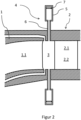
- Figure 2 shows a detailed view of a hydraulic machine according to the invention in a schematic representation.
- the cutting plane of Figure 2 is arranged parallel to the axis of rotation of the impeller 1.
- the designations correspond to the designations in Figure 1 .
- the axial boundaries of the vaneless space 3 are given by the boundaries of the water path, which allows water to flow through the hydraulic machine during operation. In turbine operation, the water flows from the guide vane 2 to the impeller 1, and in pump operation in the opposite direction.
- a hydraulic machine according to the invention comprises resonators for suppressing pressure fluctuations, of which Figure 2 one is designated 4.
- Each resonator 4 comprises a chamber, designated 5, and a pipe socket, designated 6.
- the pipe socket 6 is connected to the chamber 5 and arranged such that the end of the pipe socket 6 facing away from the chamber 4 opens into the waterway in the vaneless space 3. This ensures that during operation of the hydraulic machine the chambers 5 of the resonators 4 are filled with water and connected to the waterway via the pipe sockets 6. This means that the pipe sockets 6 are also filled with water.
- the resonators 4 are to be designed in such a way that they can suppress the undesirable pressure fluctuations.
- the internal dimensions of the chambers 5 and pipe sockets 6 are to be selected in such a way that the hydroacoustic resonance frequency of the resonators 4 is close to the frequency at which the undesirable pressure fluctuations occur. Since the pressure fluctuations are caused by the rotor-stator interaction, depending on the application and blade combination (i.e. number of rotor and guide blades), this can be the first, second or third harmonic of the rotor blade passing frequency.
- the resonators 4 have an adjustment device which enables both initial tuning and readjustment of the resonance frequency of the resonators 4 during operation.
- an adjustable stamp is to be arranged in the chambers 5, the Position can be adjusted precisely using a spindle or other device.
- One of the stamps is designated 7.
- the wall thicknesses of the resonators 4, which are to be made of steel, must be selected so that the sometimes very high static pressures and dynamic pressure fluctuations, depending on the application, can be safely absorbed.
- the resonators 4 can be arranged on both sides of the waterway.
- One of the resonators 4 is arranged on the upper side and another resonator 4 is arranged on the lower side. All of the resonators 4 could just as well be arranged at the top or all of the resonators at the bottom.
- Figure 2 shows a hydraulic machine with a vertical axis of rotation. For hydraulic machines with a horizontal axis of rotation, the Figure 2 shown arrangement is rotated by 90°.
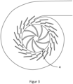
- FIG 3 shows a hydraulic machine according to the invention with an arrangement of resonators 4 in a first embodiment.
- the hydraulic machine comprises four resonators 4, which are arranged in the bladeless space in such a way that they can prevent the spread of vibrations in all directions around the impeller.
- the resonators 4 are arranged in the circumferential direction around the impeller at equal intervals.
- the in Figure 4 The hydraulic machine shown comprises 20 movable guide vanes.
- the resonators 4 are distributed in such a way that one resonator 4 is arranged on every fifth guide vane.
- the resonators 4 are arranged approximately centrally, ie in the middle in relation to the profile of the associated guide vane.
- a further even distribution of resonators 4 results in the example of the hydraulic machine shown when a total of five resonators 4 are used, with one resonator 4 being arranged on every fourth guide vane.
- a further even distribution of resonators 4 results in the example of the hydraulic machine shown when a total of ten resonators 4 are used, with one resonator 4 being arranged on every second guide vane.
- a further even distribution of resonators 4 results in the example of the hydraulic machine shown when a total of twenty resonators 4 are used, with one resonator 4 being arranged on each guide vane.
- This arrangement is in Figure 4
- a further uniform distribution of resonators 4 is obtained in the example of the hydraulic machine shown, if a total of forty resonators 4 are used, with two resonators 4 being arranged on each guide vane. This arrangement is shown in Figure 5 shown.
- FIG. 3 - 5 The hydraulic machine shown comprises nine rotor blades 1.1.
- three, nine or eighteen resonators could be arranged evenly around the rotor.
- the azimuthal orientation is not important.
- resonators 4 are not limited to the derivation from the number of guide or rotor blades.
- an arrangement could be chosen which has seven, eight, eleven, thirteen, etc. resonators 4.
- the azimuthal orientation does not play a role.
Landscapes
- Engineering & Computer Science (AREA)
- Chemical & Material Sciences (AREA)
- Combustion & Propulsion (AREA)
- Mechanical Engineering (AREA)
- General Engineering & Computer Science (AREA)
- Physics & Mathematics (AREA)
- Acoustics & Sound (AREA)
- Multimedia (AREA)
- Aviation & Aerospace Engineering (AREA)
- Fluid Mechanics (AREA)
- Hydraulic Turbines (AREA)
Description
Die Erfindung betrifft eine hydraulische Maschine mit einem Laufrad vom Typ Francis. Die Erfindung betrifft die Vermeidung von Druckschwankungen, welche beim Betrieb einer solchen hydraulischen Maschine auftreten können. Bei der hydraulischen Maschine kann es sich um eine Turbine oder um eine Pumpe oder um eine Pumpturbine handeln.The invention relates to a hydraulic machine with a Francis type impeller. The invention relates to the prevention of pressure fluctuations that can occur during operation of such a hydraulic machine. The hydraulic machine can be a turbine or a pump or a pump turbine.
Gattungsgemäße hydraulische Maschinen umfassen ein Laufrad und einen Leitapparat. Dabei ist das Laufrad dem rotierenden System und der Leitapparat dem stationären System zugeordnet. Das Laufrad umfasst eine Vielzahl von Laufschaufeln. Bei Turbinen oder Pumpturbinen umfasst der Leitapparat zwei konzentrisch angeordnete Kränze von Leitschaufeln, wobei der innen liegende Kranz beweglich gelagerte Leitschaufeln aufweist und der außen liegende Kranz unbewegliche Leitschaufeln aufweist. Die unbeweglichen Leitschaufeln werden häufig auch Traversen genannt. Bei reinen Pumpen umfasst der Leitapparat nur einen Kranz von unbeweglichen Leitschaufeln. Wenn die hydraulische Maschine durchströmt wird und sich das Laufrad dreht, können durch die gegenseitige Beeinflussung der Umströmung von stationären Leitschaufeln und rotierenden Laufschaufeln (d.h. durch Rotor-Stator-Interaktion) Druckschwankungen auftreten. Die Druckschwankungen treten in der Regel nur mit ausgewählten Frequenzen auf, die sich aus der Drehzahl und der Schaufel-Kombination ergeben. Die Druckschwankungen breiten sich in Richtung Laufrad und Spiralgehäuse, welches sich außen an den Leitapparat anschließt, aus und können dabei durch hydroakustische Resonanzeffekte (d.h. teilweise stehende Wellen) verstärkt werden. Die beschriebenen Druckschwankungen können zu inakzeptabel erhöhten Vibrationen und damit verbundenen Schallemissionen führen, insbesondere wenn sich die Druckschwankungen bis in die Druckrohrleitung ausbreiten.Generic hydraulic machines comprise an impeller and a guide vane. The impeller is assigned to the rotating system and the guide vane to the stationary system. The impeller comprises a large number of blades. In turbines or pump turbines, the guide vane comprises two concentrically arranged rings of guide vanes, with the inner ring having movably mounted guide vanes and the outer ring having immovable guide vanes. The immovable guide vanes are often also called cross members. In pure pumps, the guide vane only comprises a ring of immovable guide vanes. When there is flow through the hydraulic machine and the impeller rotates, pressure fluctuations can occur due to the mutual influence of the flow around stationary guide vanes and rotating blades (i.e. due to rotor-stator interaction). The pressure fluctuations usually only occur at selected frequencies that result from the speed and the blade combination. The pressure fluctuations spread towards the impeller and the spiral casing, which is connected to the outside of the diffuser, and can be amplified by hydroacoustic resonance effects (i.e. partially standing waves). The pressure fluctuations described can lead to unacceptably increased vibrations and associated noise emissions, especially if the pressure fluctuations spread into the pressure pipe.
Im Stand der Technik sind folgende Gegenmaßnahmen bekannt geworden. So offenbart "
Die
Die Aufgabe der Erfindung ist es, eine alternative Anordnung anzugeben, mit welcher in gattungsgemäßen hydraulischen Maschinen die beschriebenen Druckschwankungen effektiv reduziert werden können.The object of the invention is to provide an alternative arrangement with which the described pressure fluctuations can be effectively reduced in hydraulic machines of this type.
Die Aufgabe wird erfindungsgemäß durch eine Ausführung entsprechend dem unabhängigen Anspruch gelöst. Weitere vorteilhafte Ausführungsformen der vorliegenden Erfindung finden sich in den Unteransprüchen.The object is achieved according to the invention by an embodiment according to the independent claim. Further advantageous embodiments of the present invention can be found in the subclaims.
Im Folgenden wird die Erfindung anhand von Figuren erläutert. Die Figuren zeigen im Einzelnen:
- Fig.1
- Gattungsgemäße hydraulische Maschine vom Typ Francis
- Fig.2
- Detail einer erfindungsgemäßen hydraulischen Maschine
- Fig. 3
- Erfindungsgemäße hydraulische Maschine in einer ersten Ausführungsform
- Fig. 4
- Erfindungsgemäße hydraulische Maschine in einer zweiten Ausführungsform
- Fig. 5
- Erfindungsgemäße hydraulische Maschine in einer dritten Ausführungsform
- Fig.1
- Generic hydraulic machine of the Francis type
- Fig.2
- Detail of a hydraulic machine according to the invention
- Fig. 3
- Hydraulic machine according to the invention in a first embodiment
- Fig. 4
- Hydraulic machine according to the invention in a second embodiment
- Fig. 5
- Hydraulic machine according to the invention in a third embodiment
Die Resonatoren 4 sind so auszulegen, dass sie die unerwünschten Druckschwankungen unterdrücken können. Dazu sind die Innenabmessungen der Kammern 5 und Rohrstutzen 6 so zu wählen, dass die hydroakustische Resonanzfrequenz der Resonatoren 4 in der Nähe der Frequenz liegt, mit der die unerwünschten Druckschwankungen auftreten. Da die Druckschwankungen durch die Rotor-Stator-Interaktion verursacht werden, kann es sich dabei je nach Anwendung und Schaufelkombination (d.h. Anzahl von Lauf- und Leitschaufeln) um die erste, zweite oder dritte Harmonische der Laufschaufel-Passierfrequenz handeln. Da eine ausreichend genaue rechnerische Vorhersage der Resonator-Eigenschaften oft nicht möglich ist und auch Temperaturschwankungen einen nicht unerheblichen Einfluss haben können, ist es von Vorteil, wenn die Resonatoren 4 eine Verstelleinrichtung aufweisen, welche sowohl eine anfängliche Abstimmung als auch eine Nachjustierung der Resonanzfrequenz der Resonatoren 4 im laufenden Betrieb ermöglichen. Hierzu ist vorgesehen, in den Kammern 5 einen verstellbaren Stempel anzuordnen, dessen Position z.B. mittels Spindel oder einer anderen Einrichtung genau angepasst werden kann. In
Die Resonatoren 4 können an beiden Seiten des Wasserweges angeordnet sein. In
Aus den im vorhergehenden Abschnitt dargelegten Ausführungsbeispielen kann der Fachmann unschwer für jede beliebige hydraulische Maschine (d.h. für jede beliebige Anzahl von Leitschaufeln 2.1 oder 2.2) eine geeignete gleichmäßige Verteilung von Resonatoren 4 ableiten. Wie bereits erwähnt kann dabei die absolute azimutale Ausrichtung der Anordnung der Resonatoren 4 in Bezug auf die benachbarten Leitschaufeln beliebig gewählt werden.From the exemplary embodiments presented in the previous section, the person skilled in the art can easily derive a suitable uniform distribution of
Eine weitere mögliche Ableitung von gleichmäßig um das Laufrad herum verteilten Resonatoren 4 ergibt sich dadurch, dass von der Anzahl der Laufschaufeln 1.1 ausgegangen wird. Die in den
Die Verwendung einer gleichmäßigen Verteilung von Resonatoren 4 um das Laufrad herum ist jedoch nicht auf die Ableitung aus der Anzahl der Leit- oder Laufschaufeln beschränkt. So könnte beispielsweise eine Anordnung gewählt werden, welche sieben, acht, elf, dreizehn, usw. Resonatoren 4 umfasst. Auch hier spielt die azimutale Ausrichtung keine Rolle.However, the use of a uniform distribution of
Erfindungsgemäß sind alle Resonatoren 4 auf ein und dieselbe Resonanzfrequenz eingestellt.According to the invention, all
Die Untersuchungen des Erfinders haben ergeben, dass eine höhere Anzahl von Resonatoren 4 auch eine bessere Unterdrückung von Vibrationen ermöglicht. Außerdem waren in dieser Hinsicht die Anordnungen besonders vorteilhaft, welche sich bei der Ableitung der Anzahl der Resonatoren 4 an der Anzahl der Leitschaufeln orientieren. Im Sinne der Ökonomie wird der Fachmann bestrebt sein, mit möglichst wenigen Resonatoren 4 auszukommen, um die Vibrationen in ausreichendem Ausmaß zu dämpfen. Der Fachmann wird die hierzu notwendige Anzahl und Anordnung von Resonatoren 4 im Rahmen der technischen Lehre dieser Anmeldung mit Hilfe von hydro-akustischen Simulationsrechnungen bestimmen.The inventor's investigations have shown that a higher number of
Abschließend sei erwähnt, dass die technische Lehre dieser Anmeldung selbstverständlich auch dazu geeignet ist, bereits bestehende hydraulische Maschinen mit entsprechend angeordneten Resonatoren 4 nachzurüsten, um das Vibrationsverhalten dieser Maschinen zu verbessern.Finally, it should be mentioned that the technical teaching of this application is of course also suitable for retrofitting existing hydraulic machines with appropriately arranged
- 11
- Laufradwheel
- 1.11.1
- Laufschaufelblade
- 22
- Leitapparatcontrol apparatus
- 2.12.1
- Unbewegliche Leitschaufel (Traverse)Immobile guide vane (traverse)
- 2.22.2
- Bewegliche LeitschaufelMovable guide vane
- 33
- Schaufelloser Raumshovelless space
- 44
- Resonatorresonator
- 55
- Kammerchamber
- 66
- Rohrstutzenpipe socket
- 77
- StempelRubber stamp
- 88
- Spiralgehäusespiral casing
- 99
- Druckrohrleitungpressure pipeline
Claims (6)
- A hydraulic machine comprising an impeller (1) and a guide apparatus (2), wherein the impeller (1) comprises a plurality of impeller blades (1.1) and the guide apparatus (2) comprises at least one ring of guide vanes (2.1, 2.2), and wherein a vane-less space (3) extends between the impeller (1) and the guide apparatus (2), wherein the hydraulic machine comprises a plurality of resonators (4) for suppressing pressure fluctuations which may occur during operation of the hydraulic machine, and wherein each resonator (4) comprises a chamber (5), and wherein the resonators (4) are designed such that they can suppress the pressure fluctuations occurring during operation of the hydraulic machine, characterised in that each resonator (4) comprises a pipe socket (6), and in each case the pipe socket (6) is connected to the associated chamber (5), and in each case the end of the pipe socket (6) facing away from the chamber (5) opens into the bladeless space (3), and in which the number of resonators is at least three, and wherein the resonators (4) are arranged in a circumferential direction around the impeller (1) at uniform intervals, and wherein all resonators (4) are set to one and the same resonant frequency, and wherein the hydraulic machine is of the Francis type.
- Hydraulic machine according to claim 1, wherein an adjustable plunger (7) is arranged in each of the chambers (5), which is designed in such a way that the effective volume of the relevant chamber (5) can be changed by changing the position of the plunger (7) in order to adjust the resonant frequency of the relevant resonator (4).
- Hydraulic machine according to claim 1 or 2, wherein the number of resonators (4) is determined by multiplying the number of resonators (4) by a natural number to give the number of guide vanes (2.1, 2.2).
- Hydraulic machine according to claim 1 or 2, wherein the number of resonators (4) is determined by multiplying the number of guide vanes (2.1, 2.2) by a natural number to give the number of resonators (4).
- Hydraulic machine according to any one of the preceding claims, wherein the guide apparatus (2) comprises a ring of immovable guide vanes (2.1).
- Hydraulic machine according to one of the preceding claims, wherein the guide apparatus (2) comprises a ring of movable guide vanes (2.2).
Applications Claiming Priority (2)
| Application Number | Priority Date | Filing Date | Title |
|---|---|---|---|
| DE102021101197.3A DE102021101197B3 (en) | 2021-01-21 | 2021-01-21 | Francis type hydraulic machine |
| PCT/EP2021/080881 WO2022156929A1 (en) | 2021-01-21 | 2021-11-08 | Francis-type hydraulic machine |
Publications (2)
| Publication Number | Publication Date |
|---|---|
| EP4281663A1 EP4281663A1 (en) | 2023-11-29 |
| EP4281663B1 true EP4281663B1 (en) | 2024-10-23 |
Family
ID=74418426
Family Applications (1)
| Application Number | Title | Priority Date | Filing Date |
|---|---|---|---|
| EP21809958.8A Active EP4281663B1 (en) | 2021-01-21 | 2021-11-08 | Francis-type hydraulic machine |
Country Status (5)
| Country | Link |
|---|---|
| US (1) | US12037975B2 (en) |
| EP (1) | EP4281663B1 (en) |
| CN (1) | CN116745517B (en) |
| DE (1) | DE102021101197B3 (en) |
| WO (1) | WO2022156929A1 (en) |
Family Cites Families (12)
| Publication number | Priority date | Publication date | Assignee | Title |
|---|---|---|---|---|
| JPS5462434A (en) | 1977-10-26 | 1979-05-19 | Hitachi Ltd | Turning stablizing hydraulic mechanism |
| EP0050621A1 (en) | 1980-04-28 | 1982-05-05 | KOOPMANN, Gary H. | Noise reduction system |
| JPS58118273A (en) | 1982-01-06 | 1983-07-14 | Hitachi Ltd | Heat-sensitive recording head |
| JPS58118273U (en) * | 1982-02-08 | 1983-08-12 | 株式会社東芝 | Runner back pressure pulsation reduction device |
| JPS6022076A (en) * | 1983-07-15 | 1985-02-04 | Toshiba Corp | Hydraulic machine |
| US5340275A (en) * | 1993-08-02 | 1994-08-23 | Foster Wheeler Energy Corporation | Rotary throat cutoff device and method for reducing centrifugal fan noise |
| JPH11324883A (en) | 1998-03-16 | 1999-11-26 | Electric Power Dev Co Ltd | Horizontal axis hydraulic machine and operating method thereof |
| DE10210426A1 (en) * | 2002-03-09 | 2003-10-23 | Voith Siemens Hydro Power | Device for flow stabilization in hydraulic flow machines |
| DE102011005025A1 (en) * | 2011-03-03 | 2012-09-06 | Siemens Aktiengesellschaft | Resonator silencer for a radial flow machine, in particular for a centrifugal compressor |
| CN103114954B (en) * | 2012-12-07 | 2016-01-20 | 哈尔滨电机厂有限责任公司 | Improve the method for pressure pulsation of mixed-flow type pump turbine |
| EP3276157A1 (en) | 2016-07-25 | 2018-01-31 | GE Renewable Technologies | Hydraulic turbine |
| FR3068742B1 (en) * | 2017-07-07 | 2021-09-10 | Safran Aircraft Engines | TURBOMACHINE VANE INCLUDING AN IMPROVED-MOUNTED ELECTROACOUSTIC SOURCE, ROW OF OUTPUT GUIDELINES AND TURBOMACHINE INCLUDING SUCH A VANE |
-
2021
- 2021-01-21 DE DE102021101197.3A patent/DE102021101197B3/en active Active
- 2021-11-08 CN CN202180091220.8A patent/CN116745517B/en active Active
- 2021-11-08 EP EP21809958.8A patent/EP4281663B1/en active Active
- 2021-11-08 WO PCT/EP2021/080881 patent/WO2022156929A1/en not_active Ceased
-
2023
- 2023-07-20 US US18/356,077 patent/US12037975B2/en active Active
Also Published As
| Publication number | Publication date |
|---|---|
| WO2022156929A1 (en) | 2022-07-28 |
| EP4281663A1 (en) | 2023-11-29 |
| CN116745517A (en) | 2023-09-12 |
| US20230358201A1 (en) | 2023-11-09 |
| DE102021101197B3 (en) | 2022-03-10 |
| CN116745517B (en) | 2025-10-28 |
| US12037975B2 (en) | 2024-07-16 |
Similar Documents
| Publication | Publication Date | Title |
|---|---|---|
| EP1550812B1 (en) | Turbomachine | |
| EP3408503B1 (en) | Turbomachinery with bladed diffuser | |
| EP3488092A1 (en) | Flow machine and method for the production thereof | |
| DE102015000418A1 (en) | damping device | |
| DE69210462T2 (en) | Action turbines | |
| DE102015219556A1 (en) | Diffuser for radial compressor, centrifugal compressor and turbo machine with centrifugal compressor | |
| EP2041397B1 (en) | Reduction of the amplitude of rotor flexural vibrations | |
| WO2010026005A1 (en) | Turbine rotor blade having an adapted natural frequency by means of an insert | |
| EP4281663B1 (en) | Francis-type hydraulic machine | |
| DE102014212920A1 (en) | showel | |
| WO2021008816A1 (en) | Turbine casing comprising a low-stress connection flange, and exhaust-gas turbine having such a turbine casing | |
| DE102017104087A1 (en) | Method for producing a housing of a screw compressor | |
| DE10255389A1 (en) | Low pressure steam turbine has multi-channel diffuser with inner and outer diffuser rings to take blade outflow out of it | |
| DE102015016486A1 (en) | Radial turbine, turbocharger and insert for a turbine housing of the radial turbine | |
| EP2808558B1 (en) | Structure assembly for a turbomachine | |
| EP3853468B1 (en) | Pelton turbine nozzle and production method | |
| DE2831519A1 (en) | EXHAUST TURBINE FOR CHARGER | |
| EP2061953A1 (en) | Turbine of a gas turbine | |
| CH714650B1 (en) | centrifugal compressor. | |
| EP2623732A1 (en) | Assembly and method for dampening acoustic vibrations in such an assembly | |
| EP3108151A1 (en) | Nozzle plate for an axially damping hydraulic bearing | |
| DE102020115410A1 (en) | VALVE TRIM DEVICE FOR USE WITH VALVES | |
| DE102013207220B3 (en) | turbomachinery | |
| DE112008000140T5 (en) | Manifold for turbomachinery and manufacturing process | |
| DE112023003770T5 (en) | Flow control method for suppressing vibration of a radial turbine blade based on wall surface groove treatment and fluid machine |
Legal Events
| Date | Code | Title | Description |
|---|---|---|---|
| STAA | Information on the status of an ep patent application or granted ep patent |
Free format text: STATUS: UNKNOWN |
|
| STAA | Information on the status of an ep patent application or granted ep patent |
Free format text: STATUS: THE INTERNATIONAL PUBLICATION HAS BEEN MADE |
|
| PUAI | Public reference made under article 153(3) epc to a published international application that has entered the european phase |
Free format text: ORIGINAL CODE: 0009012 |
|
| STAA | Information on the status of an ep patent application or granted ep patent |
Free format text: STATUS: REQUEST FOR EXAMINATION WAS MADE |
|
| 17P | Request for examination filed |
Effective date: 20230821 |
|
| AK | Designated contracting states |
Kind code of ref document: A1 Designated state(s): AL AT BE BG CH CY CZ DE DK EE ES FI FR GB GR HR HU IE IS IT LI LT LU LV MC MK MT NL NO PL PT RO RS SE SI SK SM TR |
|
| DAV | Request for validation of the european patent (deleted) | ||
| DAX | Request for extension of the european patent (deleted) | ||
| REG | Reference to a national code |
Ref country code: DE Ref legal event code: R079 Free format text: PREVIOUS MAIN CLASS: F03B0003020000 Ipc: G10K0011160000 Ref document number: 502021005591 Country of ref document: DE |
|
| GRAP | Despatch of communication of intention to grant a patent |
Free format text: ORIGINAL CODE: EPIDOSNIGR1 |
|
| STAA | Information on the status of an ep patent application or granted ep patent |
Free format text: STATUS: GRANT OF PATENT IS INTENDED |
|
| GRAS | Grant fee paid |
Free format text: ORIGINAL CODE: EPIDOSNIGR3 |
|
| GRAA | (expected) grant |
Free format text: ORIGINAL CODE: 0009210 |
|
| STAA | Information on the status of an ep patent application or granted ep patent |
Free format text: STATUS: THE PATENT HAS BEEN GRANTED |
|
| RIC1 | Information provided on ipc code assigned before grant |
Ipc: G10K 11/172 20060101ALI20240822BHEP Ipc: F03B 11/04 20060101ALI20240822BHEP Ipc: F03B 3/02 20060101ALI20240822BHEP Ipc: G10K 11/16 20060101AFI20240822BHEP |
|
| INTG | Intention to grant announced |
Effective date: 20240909 |
|
| AK | Designated contracting states |
Kind code of ref document: B1 Designated state(s): AL AT BE BG CH CY CZ DE DK EE ES FI FR GB GR HR HU IE IS IT LI LT LU LV MC MK MT NL NO PL PT RO RS SE SI SK SM TR |
|
| REG | Reference to a national code |
Ref country code: GB Ref legal event code: FG4D Free format text: NOT ENGLISH |
|
| REG | Reference to a national code |
Ref country code: CH Ref legal event code: EP |
|
| REG | Reference to a national code |
Ref country code: DE Ref legal event code: R096 Ref document number: 502021005591 Country of ref document: DE |
|
| REG | Reference to a national code |
Ref country code: IE Ref legal event code: FG4D Free format text: LANGUAGE OF EP DOCUMENT: GERMAN |
|
| REG | Reference to a national code |
Ref country code: LT Ref legal event code: MG9D |
|
| REG | Reference to a national code |
Ref country code: NL Ref legal event code: MP Effective date: 20241023 |
|
| PG25 | Lapsed in a contracting state [announced via postgrant information from national office to epo] |
Ref country code: NL Free format text: LAPSE BECAUSE OF FAILURE TO SUBMIT A TRANSLATION OF THE DESCRIPTION OR TO PAY THE FEE WITHIN THE PRESCRIBED TIME-LIMIT Effective date: 20241023 |
|
| PG25 | Lapsed in a contracting state [announced via postgrant information from national office to epo] |
Ref country code: NL Free format text: LAPSE BECAUSE OF FAILURE TO SUBMIT A TRANSLATION OF THE DESCRIPTION OR TO PAY THE FEE WITHIN THE PRESCRIBED TIME-LIMIT Effective date: 20241023 |
|
| PG25 | Lapsed in a contracting state [announced via postgrant information from national office to epo] |
Ref country code: IS Free format text: LAPSE BECAUSE OF FAILURE TO SUBMIT A TRANSLATION OF THE DESCRIPTION OR TO PAY THE FEE WITHIN THE PRESCRIBED TIME-LIMIT Effective date: 20250223 Ref country code: HR Free format text: LAPSE BECAUSE OF FAILURE TO SUBMIT A TRANSLATION OF THE DESCRIPTION OR TO PAY THE FEE WITHIN THE PRESCRIBED TIME-LIMIT Effective date: 20241023 Ref country code: PT Free format text: LAPSE BECAUSE OF FAILURE TO SUBMIT A TRANSLATION OF THE DESCRIPTION OR TO PAY THE FEE WITHIN THE PRESCRIBED TIME-LIMIT Effective date: 20250224 |
|
| PG25 | Lapsed in a contracting state [announced via postgrant information from national office to epo] |
Ref country code: FI Free format text: LAPSE BECAUSE OF FAILURE TO SUBMIT A TRANSLATION OF THE DESCRIPTION OR TO PAY THE FEE WITHIN THE PRESCRIBED TIME-LIMIT Effective date: 20241023 |
|
| PG25 | Lapsed in a contracting state [announced via postgrant information from national office to epo] |
Ref country code: BG Free format text: LAPSE BECAUSE OF FAILURE TO SUBMIT A TRANSLATION OF THE DESCRIPTION OR TO PAY THE FEE WITHIN THE PRESCRIBED TIME-LIMIT Effective date: 20241023 |
|
| PG25 | Lapsed in a contracting state [announced via postgrant information from national office to epo] |
Ref country code: ES Free format text: LAPSE BECAUSE OF FAILURE TO SUBMIT A TRANSLATION OF THE DESCRIPTION OR TO PAY THE FEE WITHIN THE PRESCRIBED TIME-LIMIT Effective date: 20241023 |
|
| PG25 | Lapsed in a contracting state [announced via postgrant information from national office to epo] |
Ref country code: NO Free format text: LAPSE BECAUSE OF FAILURE TO SUBMIT A TRANSLATION OF THE DESCRIPTION OR TO PAY THE FEE WITHIN THE PRESCRIBED TIME-LIMIT Effective date: 20250123 |
|
| PG25 | Lapsed in a contracting state [announced via postgrant information from national office to epo] |
Ref country code: LV Free format text: LAPSE BECAUSE OF FAILURE TO SUBMIT A TRANSLATION OF THE DESCRIPTION OR TO PAY THE FEE WITHIN THE PRESCRIBED TIME-LIMIT Effective date: 20241023 Ref country code: GR Free format text: LAPSE BECAUSE OF FAILURE TO SUBMIT A TRANSLATION OF THE DESCRIPTION OR TO PAY THE FEE WITHIN THE PRESCRIBED TIME-LIMIT Effective date: 20250124 |
|
| PG25 | Lapsed in a contracting state [announced via postgrant information from national office to epo] |
Ref country code: PL Free format text: LAPSE BECAUSE OF FAILURE TO SUBMIT A TRANSLATION OF THE DESCRIPTION OR TO PAY THE FEE WITHIN THE PRESCRIBED TIME-LIMIT Effective date: 20241023 |
|
| PG25 | Lapsed in a contracting state [announced via postgrant information from national office to epo] |
Ref country code: RS Free format text: LAPSE BECAUSE OF FAILURE TO SUBMIT A TRANSLATION OF THE DESCRIPTION OR TO PAY THE FEE WITHIN THE PRESCRIBED TIME-LIMIT Effective date: 20250123 |
|
| PG25 | Lapsed in a contracting state [announced via postgrant information from national office to epo] |
Ref country code: SM Free format text: LAPSE BECAUSE OF FAILURE TO SUBMIT A TRANSLATION OF THE DESCRIPTION OR TO PAY THE FEE WITHIN THE PRESCRIBED TIME-LIMIT Effective date: 20241023 |
|
| PG25 | Lapsed in a contracting state [announced via postgrant information from national office to epo] |
Ref country code: MC Free format text: LAPSE BECAUSE OF FAILURE TO SUBMIT A TRANSLATION OF THE DESCRIPTION OR TO PAY THE FEE WITHIN THE PRESCRIBED TIME-LIMIT Effective date: 20241023 |
|
| PG25 | Lapsed in a contracting state [announced via postgrant information from national office to epo] |
Ref country code: DK Free format text: LAPSE BECAUSE OF FAILURE TO SUBMIT A TRANSLATION OF THE DESCRIPTION OR TO PAY THE FEE WITHIN THE PRESCRIBED TIME-LIMIT Effective date: 20241023 |
|
| PG25 | Lapsed in a contracting state [announced via postgrant information from national office to epo] |
Ref country code: LU Free format text: LAPSE BECAUSE OF NON-PAYMENT OF DUE FEES Effective date: 20241108 |
|
| PG25 | Lapsed in a contracting state [announced via postgrant information from national office to epo] |
Ref country code: EE Free format text: LAPSE BECAUSE OF FAILURE TO SUBMIT A TRANSLATION OF THE DESCRIPTION OR TO PAY THE FEE WITHIN THE PRESCRIBED TIME-LIMIT Effective date: 20241023 |
|
| PG25 | Lapsed in a contracting state [announced via postgrant information from national office to epo] |
Ref country code: RO Free format text: LAPSE BECAUSE OF FAILURE TO SUBMIT A TRANSLATION OF THE DESCRIPTION OR TO PAY THE FEE WITHIN THE PRESCRIBED TIME-LIMIT Effective date: 20241023 |
|
| REG | Reference to a national code |
Ref country code: DE Ref legal event code: R097 Ref document number: 502021005591 Country of ref document: DE |
|
| PG25 | Lapsed in a contracting state [announced via postgrant information from national office to epo] |
Ref country code: SK Free format text: LAPSE BECAUSE OF FAILURE TO SUBMIT A TRANSLATION OF THE DESCRIPTION OR TO PAY THE FEE WITHIN THE PRESCRIBED TIME-LIMIT Effective date: 20241023 |
|
| PG25 | Lapsed in a contracting state [announced via postgrant information from national office to epo] |
Ref country code: CZ Free format text: LAPSE BECAUSE OF FAILURE TO SUBMIT A TRANSLATION OF THE DESCRIPTION OR TO PAY THE FEE WITHIN THE PRESCRIBED TIME-LIMIT Effective date: 20241023 |
|
| PG25 | Lapsed in a contracting state [announced via postgrant information from national office to epo] |
Ref country code: IT Free format text: LAPSE BECAUSE OF FAILURE TO SUBMIT A TRANSLATION OF THE DESCRIPTION OR TO PAY THE FEE WITHIN THE PRESCRIBED TIME-LIMIT Effective date: 20241023 |
|
| REG | Reference to a national code |
Ref country code: BE Ref legal event code: MM Effective date: 20241130 |
|
| PLBE | No opposition filed within time limit |
Free format text: ORIGINAL CODE: 0009261 |
|
| STAA | Information on the status of an ep patent application or granted ep patent |
Free format text: STATUS: NO OPPOSITION FILED WITHIN TIME LIMIT |
|
| PG25 | Lapsed in a contracting state [announced via postgrant information from national office to epo] |
Ref country code: SE Free format text: LAPSE BECAUSE OF FAILURE TO SUBMIT A TRANSLATION OF THE DESCRIPTION OR TO PAY THE FEE WITHIN THE PRESCRIBED TIME-LIMIT Effective date: 20241023 |
|
| 26N | No opposition filed |
Effective date: 20250724 |
|
| PG25 | Lapsed in a contracting state [announced via postgrant information from national office to epo] |
Ref country code: BE Free format text: LAPSE BECAUSE OF NON-PAYMENT OF DUE FEES Effective date: 20241130 |
|
| PG25 | Lapsed in a contracting state [announced via postgrant information from national office to epo] |
Ref country code: IE Free format text: LAPSE BECAUSE OF NON-PAYMENT OF DUE FEES Effective date: 20241108 |
|
| REG | Reference to a national code |
Ref country code: CH Ref legal event code: U11 Free format text: ST27 STATUS EVENT CODE: U-0-0-U10-U11 (AS PROVIDED BY THE NATIONAL OFFICE) Effective date: 20251201 |
|
| PGFP | Annual fee paid to national office [announced via postgrant information from national office to epo] |
Ref country code: DE Payment date: 20251119 Year of fee payment: 5 |
|
| PGFP | Annual fee paid to national office [announced via postgrant information from national office to epo] |
Ref country code: AT Payment date: 20260113 Year of fee payment: 5 |
|
| PGFP | Annual fee paid to national office [announced via postgrant information from national office to epo] |
Ref country code: FR Payment date: 20251126 Year of fee payment: 5 |
|
| PGFP | Annual fee paid to national office [announced via postgrant information from national office to epo] |
Ref country code: CH Payment date: 20251201 Year of fee payment: 5 |
|
| PG25 | Lapsed in a contracting state [announced via postgrant information from national office to epo] |
Ref country code: HU Free format text: LAPSE BECAUSE OF FAILURE TO SUBMIT A TRANSLATION OF THE DESCRIPTION OR TO PAY THE FEE WITHIN THE PRESCRIBED TIME-LIMIT; INVALID AB INITIO Effective date: 20211108 |
|
| PG25 | Lapsed in a contracting state [announced via postgrant information from national office to epo] |
Ref country code: CY Free format text: LAPSE BECAUSE OF FAILURE TO SUBMIT A TRANSLATION OF THE DESCRIPTION OR TO PAY THE FEE WITHIN THE PRESCRIBED TIME-LIMIT; INVALID AB INITIO Effective date: 20211108 |