EP4281663B1 - Machine hydraulique de type francis - Google Patents
Machine hydraulique de type francis Download PDFInfo
- Publication number
- EP4281663B1 EP4281663B1 EP21809958.8A EP21809958A EP4281663B1 EP 4281663 B1 EP4281663 B1 EP 4281663B1 EP 21809958 A EP21809958 A EP 21809958A EP 4281663 B1 EP4281663 B1 EP 4281663B1
- Authority
- EP
- European Patent Office
- Prior art keywords
- resonators
- hydraulic machine
- impeller
- guide vanes
- guide
- Prior art date
- Legal status (The legal status is an assumption and is not a legal conclusion. Google has not performed a legal analysis and makes no representation as to the accuracy of the status listed.)
- Active
Links
Images


Classifications
-
- F—MECHANICAL ENGINEERING; LIGHTING; HEATING; WEAPONS; BLASTING
- F03—MACHINES OR ENGINES FOR LIQUIDS; WIND, SPRING, OR WEIGHT MOTORS; PRODUCING MECHANICAL POWER OR A REACTIVE PROPULSIVE THRUST, NOT OTHERWISE PROVIDED FOR
- F03B—MACHINES OR ENGINES FOR LIQUIDS
- F03B3/00—Machines or engines of reaction type; Parts or details peculiar thereto
- F03B3/02—Machines or engines of reaction type; Parts or details peculiar thereto with radial flow at high-pressure side and axial flow at low-pressure side of rotors, e.g. Francis turbines
-
- F—MECHANICAL ENGINEERING; LIGHTING; HEATING; WEAPONS; BLASTING
- F03—MACHINES OR ENGINES FOR LIQUIDS; WIND, SPRING, OR WEIGHT MOTORS; PRODUCING MECHANICAL POWER OR A REACTIVE PROPULSIVE THRUST, NOT OTHERWISE PROVIDED FOR
- F03B—MACHINES OR ENGINES FOR LIQUIDS
- F03B3/00—Machines or engines of reaction type; Parts or details peculiar thereto
- F03B3/12—Blades; Blade-carrying rotors
- F03B3/125—Rotors for radial flow at high-pressure side and axial flow at low-pressure side, e.g. for Francis-type turbines
-
- F—MECHANICAL ENGINEERING; LIGHTING; HEATING; WEAPONS; BLASTING
- F03—MACHINES OR ENGINES FOR LIQUIDS; WIND, SPRING, OR WEIGHT MOTORS; PRODUCING MECHANICAL POWER OR A REACTIVE PROPULSIVE THRUST, NOT OTHERWISE PROVIDED FOR
- F03B—MACHINES OR ENGINES FOR LIQUIDS
- F03B11/00—Parts or details not provided for in, or of interest apart from, the preceding groups, e.g. wear-protection couplings, between turbine and generator
- F03B11/04—Parts or details not provided for in, or of interest apart from, the preceding groups, e.g. wear-protection couplings, between turbine and generator for diminishing cavitation or vibration, e.g. balancing
-
- G—PHYSICS
- G10—MUSICAL INSTRUMENTS; ACOUSTICS
- G10K—SOUND-PRODUCING DEVICES; METHODS OR DEVICES FOR PROTECTING AGAINST, OR FOR DAMPING, NOISE OR OTHER ACOUSTIC WAVES IN GENERAL; ACOUSTICS NOT OTHERWISE PROVIDED FOR
- G10K11/00—Methods or devices for transmitting, conducting or directing sound in general; Methods or devices for protecting against, or for damping, noise or other acoustic waves in general
- G10K11/16—Methods or devices for protecting against, or for damping, noise or other acoustic waves in general
- G10K11/161—Methods or devices for protecting against, or for damping, noise or other acoustic waves in general in systems with fluid flow
-
- G—PHYSICS
- G10—MUSICAL INSTRUMENTS; ACOUSTICS
- G10K—SOUND-PRODUCING DEVICES; METHODS OR DEVICES FOR PROTECTING AGAINST, OR FOR DAMPING, NOISE OR OTHER ACOUSTIC WAVES IN GENERAL; ACOUSTICS NOT OTHERWISE PROVIDED FOR
- G10K11/00—Methods or devices for transmitting, conducting or directing sound in general; Methods or devices for protecting against, or for damping, noise or other acoustic waves in general
- G10K11/16—Methods or devices for protecting against, or for damping, noise or other acoustic waves in general
- G10K11/172—Methods or devices for protecting against, or for damping, noise or other acoustic waves in general using resonance effects
-
- F—MECHANICAL ENGINEERING; LIGHTING; HEATING; WEAPONS; BLASTING
- F05—INDEXING SCHEMES RELATING TO ENGINES OR PUMPS IN VARIOUS SUBCLASSES OF CLASSES F01-F04
- F05B—INDEXING SCHEME RELATING TO WIND, SPRING, WEIGHT, INERTIA OR LIKE MOTORS, TO MACHINES OR ENGINES FOR LIQUIDS COVERED BY SUBCLASSES F03B, F03D AND F03G
- F05B2270/00—Control
- F05B2270/30—Control parameters, e.g. input parameters
- F05B2270/301—Pressure
-
- Y—GENERAL TAGGING OF NEW TECHNOLOGICAL DEVELOPMENTS; GENERAL TAGGING OF CROSS-SECTIONAL TECHNOLOGIES SPANNING OVER SEVERAL SECTIONS OF THE IPC; TECHNICAL SUBJECTS COVERED BY FORMER USPC CROSS-REFERENCE ART COLLECTIONS [XRACs] AND DIGESTS
- Y02—TECHNOLOGIES OR APPLICATIONS FOR MITIGATION OR ADAPTATION AGAINST CLIMATE CHANGE
- Y02E—REDUCTION OF GREENHOUSE GAS [GHG] EMISSIONS, RELATED TO ENERGY GENERATION, TRANSMISSION OR DISTRIBUTION
- Y02E10/00—Energy generation through renewable energy sources
- Y02E10/20—Hydro energy
Definitions
- the invention relates to a hydraulic machine with a Francis type impeller.
- the invention relates to the prevention of pressure fluctuations that can occur during operation of such a hydraulic machine.
- the hydraulic machine can be a turbine or a pump or a pump turbine.
- Generic hydraulic machines comprise an impeller and a guide vane.
- the impeller is assigned to the rotating system and the guide vane to the stationary system.
- the impeller comprises a large number of blades.
- the guide vane comprises two concentrically arranged rings of guide vanes, with the inner ring having movably mounted guide vanes and the outer ring having immovable guide vanes.
- the immovable guide vanes are often also called cross members.
- the guide vane only comprises a ring of immovable guide vanes.
- the pressure fluctuations usually only occur at selected frequencies that result from the speed and the blade combination.
- the pressure fluctuations spread towards the impeller and the spiral casing, which is connected to the outside of the diffuser, and can be amplified by hydroacoustic resonance effects (i.e. partially standing waves).
- the pressure fluctuations described can lead to unacceptably increased vibrations and associated noise emissions, especially if the pressure fluctuations spread into the pressure pipe.
- the EP 0039459 A1 discloses the use of multiple resonators arranged side by side, each resonator being tuned to a different frequency. For example, one resonator may be tuned to the fundamental frequency and the other resonators may be tuned to harmonics of the fundamental frequency.
- the object of the invention is to provide an alternative arrangement with which the described pressure fluctuations can be effectively reduced in hydraulic machines of this type.
- FIG 1 shows a generic hydraulic machine of the Francis type in a schematic representation.
- the hydraulic machine comprises an impeller, which is designated with 1, and a guide device, which is designated with 2.
- the viewing direction of the Figure 1 coincides with the axis of rotation of the impeller.
- the impeller 1 comprises a plurality of blades, one of which is designated 1.1.
- the guide device 2 comprises a ring of immovable guide vanes, one of which is designated 2.1.
- the immovable guide vanes 2.1 are often also referred to as cross members.
- the guide device 2 further comprises a ring of movable guide vanes, one of which is designated 2.2.
- the in Figure 1 The configuration shown with movable guide vanes 2.2 is generally used in turbines and pump turbines.
- the ring with movable guide vanes is omitted. 2.2, which is therefore to be considered optional.
- the guide vane 2 encloses the impeller 1 in the Figure 1
- the so-called vaneless space extends between the diffuser 2 and the impeller, which is Figure 1 shown hatched and designated 3.
- the guide apparatus 2 comprises movable guide vanes 2.2, then the outer boundary of the vaneless space 3 is formed by a cylinder jacket which touches but does not intersect the movable guide vanes 2.2 when they are in a position in which they come as close as possible to the impeller 1. This is the so-called open position of the guide apparatus.
- the outer boundary of the vaneless space 3 is formed by a cylinder jacket which touches but does not intersect the immovable guide vanes 2.1.
- the inner boundary of the vaneless space 3 is formed by a cylinder jacket which touches but does not intersect the impeller 1.
- the vaneless space 3 is therefore essentially a tubular cylinder, with the impeller 1 located inside the tubular cylinder and the guide apparatus 2 extending outside the tubular cylinder.
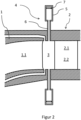
- Figure 2 shows a detailed view of a hydraulic machine according to the invention in a schematic representation.
- the cutting plane of Figure 2 is arranged parallel to the axis of rotation of the impeller 1.
- the designations correspond to the designations in Figure 1 .
- the axial boundaries of the vaneless space 3 are given by the boundaries of the water path, which allows water to flow through the hydraulic machine during operation. In turbine operation, the water flows from the guide vane 2 to the impeller 1, and in pump operation in the opposite direction.
- a hydraulic machine according to the invention comprises resonators for suppressing pressure fluctuations, of which Figure 2 one is designated 4.
- Each resonator 4 comprises a chamber, designated 5, and a pipe socket, designated 6.
- the pipe socket 6 is connected to the chamber 5 and arranged such that the end of the pipe socket 6 facing away from the chamber 4 opens into the waterway in the vaneless space 3. This ensures that during operation of the hydraulic machine the chambers 5 of the resonators 4 are filled with water and connected to the waterway via the pipe sockets 6. This means that the pipe sockets 6 are also filled with water.
- the resonators 4 are to be designed in such a way that they can suppress the undesirable pressure fluctuations.
- the internal dimensions of the chambers 5 and pipe sockets 6 are to be selected in such a way that the hydroacoustic resonance frequency of the resonators 4 is close to the frequency at which the undesirable pressure fluctuations occur. Since the pressure fluctuations are caused by the rotor-stator interaction, depending on the application and blade combination (i.e. number of rotor and guide blades), this can be the first, second or third harmonic of the rotor blade passing frequency.
- the resonators 4 have an adjustment device which enables both initial tuning and readjustment of the resonance frequency of the resonators 4 during operation.
- an adjustable stamp is to be arranged in the chambers 5, the Position can be adjusted precisely using a spindle or other device.
- One of the stamps is designated 7.
- the wall thicknesses of the resonators 4, which are to be made of steel, must be selected so that the sometimes very high static pressures and dynamic pressure fluctuations, depending on the application, can be safely absorbed.
- the resonators 4 can be arranged on both sides of the waterway.
- One of the resonators 4 is arranged on the upper side and another resonator 4 is arranged on the lower side. All of the resonators 4 could just as well be arranged at the top or all of the resonators at the bottom.
- Figure 2 shows a hydraulic machine with a vertical axis of rotation. For hydraulic machines with a horizontal axis of rotation, the Figure 2 shown arrangement is rotated by 90°.
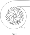
- FIG 3 shows a hydraulic machine according to the invention with an arrangement of resonators 4 in a first embodiment.
- the hydraulic machine comprises four resonators 4, which are arranged in the bladeless space in such a way that they can prevent the spread of vibrations in all directions around the impeller.
- the resonators 4 are arranged in the circumferential direction around the impeller at equal intervals.
- the in Figure 4 The hydraulic machine shown comprises 20 movable guide vanes.
- the resonators 4 are distributed in such a way that one resonator 4 is arranged on every fifth guide vane.
- the resonators 4 are arranged approximately centrally, ie in the middle in relation to the profile of the associated guide vane.
- a further even distribution of resonators 4 results in the example of the hydraulic machine shown when a total of five resonators 4 are used, with one resonator 4 being arranged on every fourth guide vane.
- a further even distribution of resonators 4 results in the example of the hydraulic machine shown when a total of ten resonators 4 are used, with one resonator 4 being arranged on every second guide vane.
- a further even distribution of resonators 4 results in the example of the hydraulic machine shown when a total of twenty resonators 4 are used, with one resonator 4 being arranged on each guide vane.
- This arrangement is in Figure 4
- a further uniform distribution of resonators 4 is obtained in the example of the hydraulic machine shown, if a total of forty resonators 4 are used, with two resonators 4 being arranged on each guide vane. This arrangement is shown in Figure 5 shown.
- FIG. 3 - 5 The hydraulic machine shown comprises nine rotor blades 1.1.
- three, nine or eighteen resonators could be arranged evenly around the rotor.
- the azimuthal orientation is not important.
- resonators 4 are not limited to the derivation from the number of guide or rotor blades.
- an arrangement could be chosen which has seven, eight, eleven, thirteen, etc. resonators 4.
- the azimuthal orientation does not play a role.
Landscapes
- Engineering & Computer Science (AREA)
- Chemical & Material Sciences (AREA)
- Combustion & Propulsion (AREA)
- Mechanical Engineering (AREA)
- General Engineering & Computer Science (AREA)
- Physics & Mathematics (AREA)
- Acoustics & Sound (AREA)
- Multimedia (AREA)
- Aviation & Aerospace Engineering (AREA)
- Fluid Mechanics (AREA)
- Hydraulic Turbines (AREA)
Claims (6)
- Machine hydraulique comprenant un rotor (1) et un distributeur (2), le rotor (1) comprenant une pluralité d'aubes mobiles (1.1) et le distributeur (2) comprenant au moins une couronne d'aubes directrices (2.1, 2.2), et dans lequel un espace sans aubes (3) s'étend entre la roue (1) et le distributeur (2), dans lequel la machine hydraulique comprend une pluralité de résonateurs (4) pour supprimer les variations de pression qui peuvent se produire pendant le fonctionnement de la machine hydraulique, et dans lequel chaque résonateur (4) comprend une chambre (5), et dans lequel les résonateurs (4) sont conçus pour supprimer les variations de pression qui se produisent pendant le fonctionnement de la machine hydraulique, caractérisé en ce que chaque résonateur (4) comprend une tubulure (6), et dans lequel chaque tubulure (6) est reliée à la chambre (5) correspondante, et dans lequel chaque extrémité de la tubulure (6) opposée à la chambre (5) débouche dans l'espace sans aubes (3), et dans lequel le nombre de résonateurs est d'au moins trois, et dans lequel les résonateurs (4) sont disposés à intervalles réguliers dans la direction circonférentielle autour de la roue (1), et dans lequel tous les résonateurs (4) sont réglés sur une seule et même fréquence de résonance, et dans lequel la machine hydraulique est du type Francis.
- Machine hydraulique selon la revendication 1, dans laquelle un poinçon réglable (7) est disposé dans chacune des chambres (5), lequel est conçu de telle sorte qu'un changement de position du poinçon (7) permet de modifier le volume efficace de la chambre (5) concernée afin d'ajuster la fréquence de résonance du résonateur (4) concerné.
- Machine hydraulique selon la revendication 1 ou 2, dans laquelle le nombre de résonateurs (4) est déterminé par le fait que le nombre de résonateurs (4) multiplié par un nombre naturel donne le nombre d'aubes directrices (2.1, 2.2).
- Machine hydraulique selon la revendication 1 ou 2, dans laquelle le nombre de résonateurs (4) est déterminé par le fait que le nombre d'aubes directrices (2.1, 2.2) multiplié par un nombre naturel donne le nombre de résonateurs (4).
- Machine hydraulique selon l'une quelconque des revendications précédentes, dans laquelle le distributeur (2) comprend une couronne d'aubes directrices immobiles (2.1).
- Machine hydraulique selon l'une quelconque des revendications précédentes, dans laquelle le distributeur (2) comprend une couronne d'aubes directrices mobiles (2.2).
Applications Claiming Priority (2)
| Application Number | Priority Date | Filing Date | Title |
|---|---|---|---|
| DE102021101197.3A DE102021101197B3 (de) | 2021-01-21 | 2021-01-21 | Hydraulische Maschine vom Typ Francis |
| PCT/EP2021/080881 WO2022156929A1 (fr) | 2021-01-21 | 2021-11-08 | Machine hydraulique de type francis |
Publications (2)
| Publication Number | Publication Date |
|---|---|
| EP4281663A1 EP4281663A1 (fr) | 2023-11-29 |
| EP4281663B1 true EP4281663B1 (fr) | 2024-10-23 |
Family
ID=74418426
Family Applications (1)
| Application Number | Title | Priority Date | Filing Date |
|---|---|---|---|
| EP21809958.8A Active EP4281663B1 (fr) | 2021-01-21 | 2021-11-08 | Machine hydraulique de type francis |
Country Status (5)
| Country | Link |
|---|---|
| US (1) | US12037975B2 (fr) |
| EP (1) | EP4281663B1 (fr) |
| CN (1) | CN116745517B (fr) |
| DE (1) | DE102021101197B3 (fr) |
| WO (1) | WO2022156929A1 (fr) |
Family Cites Families (12)
| Publication number | Priority date | Publication date | Assignee | Title |
|---|---|---|---|---|
| JPS5462434A (en) | 1977-10-26 | 1979-05-19 | Hitachi Ltd | Turning stablizing hydraulic mechanism |
| EP0050621A1 (fr) | 1980-04-28 | 1982-05-05 | KOOPMANN, Gary H. | Systeme de reduction du bruit |
| JPS58118273A (ja) | 1982-01-06 | 1983-07-14 | Hitachi Ltd | 感熱記録ヘツド |
| JPS58118273U (ja) * | 1982-02-08 | 1983-08-12 | 株式会社東芝 | ランナ背圧脈動軽減装置 |
| JPS6022076A (ja) * | 1983-07-15 | 1985-02-04 | Toshiba Corp | 水力機械 |
| US5340275A (en) * | 1993-08-02 | 1994-08-23 | Foster Wheeler Energy Corporation | Rotary throat cutoff device and method for reducing centrifugal fan noise |
| JPH11324883A (ja) | 1998-03-16 | 1999-11-26 | Electric Power Dev Co Ltd | 横軸水力機械およびその運転方法 |
| DE10210426A1 (de) * | 2002-03-09 | 2003-10-23 | Voith Siemens Hydro Power | Vorrichtung zur Strömungsstabilisierung in hydraulischen Strömungsmaschinen |
| DE102011005025A1 (de) * | 2011-03-03 | 2012-09-06 | Siemens Aktiengesellschaft | Resonatorschalldämpfer für eine radiale Strömungsmaschine, insbesondere für einen Radialverdichter |
| CN103114954B (zh) * | 2012-12-07 | 2016-01-20 | 哈尔滨电机厂有限责任公司 | 改善混流式水泵水轮机压力脉动的方法 |
| EP3276157A1 (fr) | 2016-07-25 | 2018-01-31 | GE Renewable Technologies | Turbine hydraulique |
| FR3068742B1 (fr) * | 2017-07-07 | 2021-09-10 | Safran Aircraft Engines | Aube de turbomachine comprenant une source electroacoustique a montage ameliore, rangee d'aubes directrices de sortie et turbomachine comprenant une telle aube |
-
2021
- 2021-01-21 DE DE102021101197.3A patent/DE102021101197B3/de active Active
- 2021-11-08 CN CN202180091220.8A patent/CN116745517B/zh active Active
- 2021-11-08 EP EP21809958.8A patent/EP4281663B1/fr active Active
- 2021-11-08 WO PCT/EP2021/080881 patent/WO2022156929A1/fr not_active Ceased
-
2023
- 2023-07-20 US US18/356,077 patent/US12037975B2/en active Active
Also Published As
| Publication number | Publication date |
|---|---|
| WO2022156929A1 (fr) | 2022-07-28 |
| EP4281663A1 (fr) | 2023-11-29 |
| CN116745517A (zh) | 2023-09-12 |
| US20230358201A1 (en) | 2023-11-09 |
| DE102021101197B3 (de) | 2022-03-10 |
| CN116745517B (zh) | 2025-10-28 |
| US12037975B2 (en) | 2024-07-16 |
Similar Documents
| Publication | Publication Date | Title |
|---|---|---|
| EP1550812B1 (fr) | Turbomachine | |
| EP3408503B1 (fr) | Turbomachine avec diffuseur à aubes | |
| EP3488092A1 (fr) | Turbomachine et son procédé de fabrication | |
| DE102015000418A1 (de) | Dämpfungsvorrichtung | |
| DE69210462T2 (de) | Aktionsturbinen | |
| DE102015219556A1 (de) | Diffusor für Radialverdichter, Radialverdichter und Turbomaschine mit Radialverdichter | |
| EP2041397B1 (fr) | Réduction d'amplitude de vibrations flexurales d'un rotor | |
| WO2010026005A1 (fr) | Aube de turbine à fréquence propre adaptée au moyen d'un élément rapporté | |
| EP4281663B1 (fr) | Machine hydraulique de type francis | |
| DE102014212920A1 (de) | Schaufelpumpe | |
| WO2021008816A1 (fr) | Carter de turbine comportant une bride de liaison à faible tension et une turbine de gaz d'échappement comportant un tel carter de turbine | |
| DE102017104087A1 (de) | Verfahren zur Herstellung eines Gehäuses eines Schraubenkompressors | |
| DE10255389A1 (de) | Niederdruckdampfturbine mit Mehrkanal-Diffusor | |
| DE102015016486A1 (de) | Radialturbine, Turbolader und Einsatzstück für ein Turbinengehäuse der Radialturbine | |
| EP2808558B1 (fr) | Ensemble structurel pour une turbomachine | |
| EP3853468B1 (fr) | Buse de turbines pelton et procédé de fabrication | |
| DE2831519A1 (de) | Abgasturbine fuer auflader | |
| EP2061953A1 (fr) | Turbine d'une turbine à gaz | |
| CH714650B1 (de) | Radialverdichter. | |
| EP2623732A1 (fr) | Installation et procédé destinés à amortir des vibrations acoustiques dans une installation associée | |
| EP3108151A1 (fr) | Plaque perforée pour palier hydraulique à amortissement axial | |
| DE102020115410A1 (de) | Ventiltrimmvorrichtung zur verwendung mit ventilen | |
| DE102013207220B3 (de) | Turbomaschine | |
| DE112008000140T5 (de) | Leitapparat für Turbomaschinen und Herstellungsverfahren | |
| DE112023003770T5 (de) | Strömungssteuerungsverfahren zum Unterdrücken einer Schwingung einer Radialturbinenschaufel auf der Grundlage einer Wandflächenrillenbehandlung und Strömungsmaschine |
Legal Events
| Date | Code | Title | Description |
|---|---|---|---|
| STAA | Information on the status of an ep patent application or granted ep patent |
Free format text: STATUS: UNKNOWN |
|
| STAA | Information on the status of an ep patent application or granted ep patent |
Free format text: STATUS: THE INTERNATIONAL PUBLICATION HAS BEEN MADE |
|
| PUAI | Public reference made under article 153(3) epc to a published international application that has entered the european phase |
Free format text: ORIGINAL CODE: 0009012 |
|
| STAA | Information on the status of an ep patent application or granted ep patent |
Free format text: STATUS: REQUEST FOR EXAMINATION WAS MADE |
|
| 17P | Request for examination filed |
Effective date: 20230821 |
|
| AK | Designated contracting states |
Kind code of ref document: A1 Designated state(s): AL AT BE BG CH CY CZ DE DK EE ES FI FR GB GR HR HU IE IS IT LI LT LU LV MC MK MT NL NO PL PT RO RS SE SI SK SM TR |
|
| DAV | Request for validation of the european patent (deleted) | ||
| DAX | Request for extension of the european patent (deleted) | ||
| REG | Reference to a national code |
Ref country code: DE Ref legal event code: R079 Free format text: PREVIOUS MAIN CLASS: F03B0003020000 Ipc: G10K0011160000 Ref document number: 502021005591 Country of ref document: DE |
|
| GRAP | Despatch of communication of intention to grant a patent |
Free format text: ORIGINAL CODE: EPIDOSNIGR1 |
|
| STAA | Information on the status of an ep patent application or granted ep patent |
Free format text: STATUS: GRANT OF PATENT IS INTENDED |
|
| GRAS | Grant fee paid |
Free format text: ORIGINAL CODE: EPIDOSNIGR3 |
|
| GRAA | (expected) grant |
Free format text: ORIGINAL CODE: 0009210 |
|
| STAA | Information on the status of an ep patent application or granted ep patent |
Free format text: STATUS: THE PATENT HAS BEEN GRANTED |
|
| RIC1 | Information provided on ipc code assigned before grant |
Ipc: G10K 11/172 20060101ALI20240822BHEP Ipc: F03B 11/04 20060101ALI20240822BHEP Ipc: F03B 3/02 20060101ALI20240822BHEP Ipc: G10K 11/16 20060101AFI20240822BHEP |
|
| INTG | Intention to grant announced |
Effective date: 20240909 |
|
| AK | Designated contracting states |
Kind code of ref document: B1 Designated state(s): AL AT BE BG CH CY CZ DE DK EE ES FI FR GB GR HR HU IE IS IT LI LT LU LV MC MK MT NL NO PL PT RO RS SE SI SK SM TR |
|
| REG | Reference to a national code |
Ref country code: GB Ref legal event code: FG4D Free format text: NOT ENGLISH |
|
| REG | Reference to a national code |
Ref country code: CH Ref legal event code: EP |
|
| REG | Reference to a national code |
Ref country code: DE Ref legal event code: R096 Ref document number: 502021005591 Country of ref document: DE |
|
| REG | Reference to a national code |
Ref country code: IE Ref legal event code: FG4D Free format text: LANGUAGE OF EP DOCUMENT: GERMAN |
|
| REG | Reference to a national code |
Ref country code: LT Ref legal event code: MG9D |
|
| REG | Reference to a national code |
Ref country code: NL Ref legal event code: MP Effective date: 20241023 |
|
| PG25 | Lapsed in a contracting state [announced via postgrant information from national office to epo] |
Ref country code: NL Free format text: LAPSE BECAUSE OF FAILURE TO SUBMIT A TRANSLATION OF THE DESCRIPTION OR TO PAY THE FEE WITHIN THE PRESCRIBED TIME-LIMIT Effective date: 20241023 |
|
| PG25 | Lapsed in a contracting state [announced via postgrant information from national office to epo] |
Ref country code: NL Free format text: LAPSE BECAUSE OF FAILURE TO SUBMIT A TRANSLATION OF THE DESCRIPTION OR TO PAY THE FEE WITHIN THE PRESCRIBED TIME-LIMIT Effective date: 20241023 |
|
| PG25 | Lapsed in a contracting state [announced via postgrant information from national office to epo] |
Ref country code: IS Free format text: LAPSE BECAUSE OF FAILURE TO SUBMIT A TRANSLATION OF THE DESCRIPTION OR TO PAY THE FEE WITHIN THE PRESCRIBED TIME-LIMIT Effective date: 20250223 Ref country code: HR Free format text: LAPSE BECAUSE OF FAILURE TO SUBMIT A TRANSLATION OF THE DESCRIPTION OR TO PAY THE FEE WITHIN THE PRESCRIBED TIME-LIMIT Effective date: 20241023 Ref country code: PT Free format text: LAPSE BECAUSE OF FAILURE TO SUBMIT A TRANSLATION OF THE DESCRIPTION OR TO PAY THE FEE WITHIN THE PRESCRIBED TIME-LIMIT Effective date: 20250224 |
|
| PG25 | Lapsed in a contracting state [announced via postgrant information from national office to epo] |
Ref country code: FI Free format text: LAPSE BECAUSE OF FAILURE TO SUBMIT A TRANSLATION OF THE DESCRIPTION OR TO PAY THE FEE WITHIN THE PRESCRIBED TIME-LIMIT Effective date: 20241023 |
|
| PG25 | Lapsed in a contracting state [announced via postgrant information from national office to epo] |
Ref country code: BG Free format text: LAPSE BECAUSE OF FAILURE TO SUBMIT A TRANSLATION OF THE DESCRIPTION OR TO PAY THE FEE WITHIN THE PRESCRIBED TIME-LIMIT Effective date: 20241023 |
|
| PG25 | Lapsed in a contracting state [announced via postgrant information from national office to epo] |
Ref country code: ES Free format text: LAPSE BECAUSE OF FAILURE TO SUBMIT A TRANSLATION OF THE DESCRIPTION OR TO PAY THE FEE WITHIN THE PRESCRIBED TIME-LIMIT Effective date: 20241023 |
|
| PG25 | Lapsed in a contracting state [announced via postgrant information from national office to epo] |
Ref country code: NO Free format text: LAPSE BECAUSE OF FAILURE TO SUBMIT A TRANSLATION OF THE DESCRIPTION OR TO PAY THE FEE WITHIN THE PRESCRIBED TIME-LIMIT Effective date: 20250123 |
|
| PG25 | Lapsed in a contracting state [announced via postgrant information from national office to epo] |
Ref country code: LV Free format text: LAPSE BECAUSE OF FAILURE TO SUBMIT A TRANSLATION OF THE DESCRIPTION OR TO PAY THE FEE WITHIN THE PRESCRIBED TIME-LIMIT Effective date: 20241023 Ref country code: GR Free format text: LAPSE BECAUSE OF FAILURE TO SUBMIT A TRANSLATION OF THE DESCRIPTION OR TO PAY THE FEE WITHIN THE PRESCRIBED TIME-LIMIT Effective date: 20250124 |
|
| PG25 | Lapsed in a contracting state [announced via postgrant information from national office to epo] |
Ref country code: PL Free format text: LAPSE BECAUSE OF FAILURE TO SUBMIT A TRANSLATION OF THE DESCRIPTION OR TO PAY THE FEE WITHIN THE PRESCRIBED TIME-LIMIT Effective date: 20241023 |
|
| PG25 | Lapsed in a contracting state [announced via postgrant information from national office to epo] |
Ref country code: RS Free format text: LAPSE BECAUSE OF FAILURE TO SUBMIT A TRANSLATION OF THE DESCRIPTION OR TO PAY THE FEE WITHIN THE PRESCRIBED TIME-LIMIT Effective date: 20250123 |
|
| PG25 | Lapsed in a contracting state [announced via postgrant information from national office to epo] |
Ref country code: SM Free format text: LAPSE BECAUSE OF FAILURE TO SUBMIT A TRANSLATION OF THE DESCRIPTION OR TO PAY THE FEE WITHIN THE PRESCRIBED TIME-LIMIT Effective date: 20241023 |
|
| PG25 | Lapsed in a contracting state [announced via postgrant information from national office to epo] |
Ref country code: MC Free format text: LAPSE BECAUSE OF FAILURE TO SUBMIT A TRANSLATION OF THE DESCRIPTION OR TO PAY THE FEE WITHIN THE PRESCRIBED TIME-LIMIT Effective date: 20241023 |
|
| PG25 | Lapsed in a contracting state [announced via postgrant information from national office to epo] |
Ref country code: DK Free format text: LAPSE BECAUSE OF FAILURE TO SUBMIT A TRANSLATION OF THE DESCRIPTION OR TO PAY THE FEE WITHIN THE PRESCRIBED TIME-LIMIT Effective date: 20241023 |
|
| PG25 | Lapsed in a contracting state [announced via postgrant information from national office to epo] |
Ref country code: LU Free format text: LAPSE BECAUSE OF NON-PAYMENT OF DUE FEES Effective date: 20241108 |
|
| PG25 | Lapsed in a contracting state [announced via postgrant information from national office to epo] |
Ref country code: EE Free format text: LAPSE BECAUSE OF FAILURE TO SUBMIT A TRANSLATION OF THE DESCRIPTION OR TO PAY THE FEE WITHIN THE PRESCRIBED TIME-LIMIT Effective date: 20241023 |
|
| PG25 | Lapsed in a contracting state [announced via postgrant information from national office to epo] |
Ref country code: RO Free format text: LAPSE BECAUSE OF FAILURE TO SUBMIT A TRANSLATION OF THE DESCRIPTION OR TO PAY THE FEE WITHIN THE PRESCRIBED TIME-LIMIT Effective date: 20241023 |
|
| REG | Reference to a national code |
Ref country code: DE Ref legal event code: R097 Ref document number: 502021005591 Country of ref document: DE |
|
| PG25 | Lapsed in a contracting state [announced via postgrant information from national office to epo] |
Ref country code: SK Free format text: LAPSE BECAUSE OF FAILURE TO SUBMIT A TRANSLATION OF THE DESCRIPTION OR TO PAY THE FEE WITHIN THE PRESCRIBED TIME-LIMIT Effective date: 20241023 |
|
| PG25 | Lapsed in a contracting state [announced via postgrant information from national office to epo] |
Ref country code: CZ Free format text: LAPSE BECAUSE OF FAILURE TO SUBMIT A TRANSLATION OF THE DESCRIPTION OR TO PAY THE FEE WITHIN THE PRESCRIBED TIME-LIMIT Effective date: 20241023 |
|
| PG25 | Lapsed in a contracting state [announced via postgrant information from national office to epo] |
Ref country code: IT Free format text: LAPSE BECAUSE OF FAILURE TO SUBMIT A TRANSLATION OF THE DESCRIPTION OR TO PAY THE FEE WITHIN THE PRESCRIBED TIME-LIMIT Effective date: 20241023 |
|
| REG | Reference to a national code |
Ref country code: BE Ref legal event code: MM Effective date: 20241130 |
|
| PLBE | No opposition filed within time limit |
Free format text: ORIGINAL CODE: 0009261 |
|
| STAA | Information on the status of an ep patent application or granted ep patent |
Free format text: STATUS: NO OPPOSITION FILED WITHIN TIME LIMIT |
|
| PG25 | Lapsed in a contracting state [announced via postgrant information from national office to epo] |
Ref country code: SE Free format text: LAPSE BECAUSE OF FAILURE TO SUBMIT A TRANSLATION OF THE DESCRIPTION OR TO PAY THE FEE WITHIN THE PRESCRIBED TIME-LIMIT Effective date: 20241023 |
|
| 26N | No opposition filed |
Effective date: 20250724 |
|
| PG25 | Lapsed in a contracting state [announced via postgrant information from national office to epo] |
Ref country code: BE Free format text: LAPSE BECAUSE OF NON-PAYMENT OF DUE FEES Effective date: 20241130 |
|
| PG25 | Lapsed in a contracting state [announced via postgrant information from national office to epo] |
Ref country code: IE Free format text: LAPSE BECAUSE OF NON-PAYMENT OF DUE FEES Effective date: 20241108 |
|
| REG | Reference to a national code |
Ref country code: CH Ref legal event code: U11 Free format text: ST27 STATUS EVENT CODE: U-0-0-U10-U11 (AS PROVIDED BY THE NATIONAL OFFICE) Effective date: 20251201 |
|
| PGFP | Annual fee paid to national office [announced via postgrant information from national office to epo] |
Ref country code: DE Payment date: 20251119 Year of fee payment: 5 |
|
| PGFP | Annual fee paid to national office [announced via postgrant information from national office to epo] |
Ref country code: AT Payment date: 20260113 Year of fee payment: 5 |
|
| PGFP | Annual fee paid to national office [announced via postgrant information from national office to epo] |
Ref country code: FR Payment date: 20251126 Year of fee payment: 5 |
|
| PGFP | Annual fee paid to national office [announced via postgrant information from national office to epo] |
Ref country code: CH Payment date: 20251201 Year of fee payment: 5 |
|
| PG25 | Lapsed in a contracting state [announced via postgrant information from national office to epo] |
Ref country code: HU Free format text: LAPSE BECAUSE OF FAILURE TO SUBMIT A TRANSLATION OF THE DESCRIPTION OR TO PAY THE FEE WITHIN THE PRESCRIBED TIME-LIMIT; INVALID AB INITIO Effective date: 20211108 |
|
| PG25 | Lapsed in a contracting state [announced via postgrant information from national office to epo] |
Ref country code: CY Free format text: LAPSE BECAUSE OF FAILURE TO SUBMIT A TRANSLATION OF THE DESCRIPTION OR TO PAY THE FEE WITHIN THE PRESCRIBED TIME-LIMIT; INVALID AB INITIO Effective date: 20211108 |