EP4281365B1 - Systeme und verfahren zur steuerung eines elektrischen senkrecht startenden und landenden flugzeugs - Google Patents
Systeme und verfahren zur steuerung eines elektrischen senkrecht startenden und landenden flugzeugs Download PDFInfo
- Publication number
- EP4281365B1 EP4281365B1 EP22703539.1A EP22703539A EP4281365B1 EP 4281365 B1 EP4281365 B1 EP 4281365B1 EP 22703539 A EP22703539 A EP 22703539A EP 4281365 B1 EP4281365 B1 EP 4281365B1
- Authority
- EP
- European Patent Office
- Prior art keywords
- aircraft
- electric
- propulsion units
- electric propulsion
- actuators
- Prior art date
- Legal status (The legal status is an assumption and is not a legal conclusion. Google has not performed a legal analysis and makes no representation as to the accuracy of the status listed.)
- Active
Links
Images


Classifications
-
- G—PHYSICS
- G05—CONTROLLING; REGULATING
- G05D—SYSTEMS FOR CONTROLLING OR REGULATING NON-ELECTRIC VARIABLES
- G05D1/00—Control of position, course, altitude or attitude of land, water, air or space vehicles, e.g. using automatic pilots
- G05D1/40—Control within particular dimensions
- G05D1/49—Control of attitude, i.e. control of roll, pitch or yaw
-
- B—PERFORMING OPERATIONS; TRANSPORTING
- B64—AIRCRAFT; AVIATION; COSMONAUTICS
- B64D—EQUIPMENT FOR FITTING IN OR TO AIRCRAFT; FLIGHT SUITS; PARACHUTES; ARRANGEMENT OR MOUNTING OF POWER PLANTS OR PROPULSION TRANSMISSIONS IN AIRCRAFT
- B64D31/00—Power plant control systems; Arrangement of power plant control systems in aircraft
- B64D31/02—Initiating means
-
- B—PERFORMING OPERATIONS; TRANSPORTING
- B60—VEHICLES IN GENERAL
- B60L—PROPULSION OF ELECTRICALLY-PROPELLED VEHICLES; SUPPLYING ELECTRIC POWER FOR AUXILIARY EQUIPMENT OF ELECTRICALLY-PROPELLED VEHICLES; ELECTRODYNAMIC BRAKE SYSTEMS FOR VEHICLES IN GENERAL; MAGNETIC SUSPENSION OR LEVITATION FOR VEHICLES; MONITORING OPERATING VARIABLES OF ELECTRICALLY-PROPELLED VEHICLES; ELECTRIC SAFETY DEVICES FOR ELECTRICALLY-PROPELLED VEHICLES
- B60L50/00—Electric propulsion with power supplied within the vehicle
- B60L50/50—Electric propulsion with power supplied within the vehicle using propulsion power supplied by batteries or fuel cells
- B60L50/60—Electric propulsion with power supplied within the vehicle using propulsion power supplied by batteries or fuel cells using power supplied by batteries
-
- B—PERFORMING OPERATIONS; TRANSPORTING
- B60—VEHICLES IN GENERAL
- B60L—PROPULSION OF ELECTRICALLY-PROPELLED VEHICLES; SUPPLYING ELECTRIC POWER FOR AUXILIARY EQUIPMENT OF ELECTRICALLY-PROPELLED VEHICLES; ELECTRODYNAMIC BRAKE SYSTEMS FOR VEHICLES IN GENERAL; MAGNETIC SUSPENSION OR LEVITATION FOR VEHICLES; MONITORING OPERATING VARIABLES OF ELECTRICALLY-PROPELLED VEHICLES; ELECTRIC SAFETY DEVICES FOR ELECTRICALLY-PROPELLED VEHICLES
- B60L58/00—Methods or circuit arrangements for monitoring or controlling batteries or fuel cells, specially adapted for electric vehicles
- B60L58/10—Methods or circuit arrangements for monitoring or controlling batteries or fuel cells, specially adapted for electric vehicles for monitoring or controlling batteries
- B60L58/12—Methods or circuit arrangements for monitoring or controlling batteries or fuel cells, specially adapted for electric vehicles for monitoring or controlling batteries responding to state of charge [SoC]
-
- B—PERFORMING OPERATIONS; TRANSPORTING
- B60—VEHICLES IN GENERAL
- B60L—PROPULSION OF ELECTRICALLY-PROPELLED VEHICLES; SUPPLYING ELECTRIC POWER FOR AUXILIARY EQUIPMENT OF ELECTRICALLY-PROPELLED VEHICLES; ELECTRODYNAMIC BRAKE SYSTEMS FOR VEHICLES IN GENERAL; MAGNETIC SUSPENSION OR LEVITATION FOR VEHICLES; MONITORING OPERATING VARIABLES OF ELECTRICALLY-PROPELLED VEHICLES; ELECTRIC SAFETY DEVICES FOR ELECTRICALLY-PROPELLED VEHICLES
- B60L58/00—Methods or circuit arrangements for monitoring or controlling batteries or fuel cells, specially adapted for electric vehicles
- B60L58/10—Methods or circuit arrangements for monitoring or controlling batteries or fuel cells, specially adapted for electric vehicles for monitoring or controlling batteries
- B60L58/18—Methods or circuit arrangements for monitoring or controlling batteries or fuel cells, specially adapted for electric vehicles for monitoring or controlling batteries of two or more battery modules
-
- B—PERFORMING OPERATIONS; TRANSPORTING
- B64—AIRCRAFT; AVIATION; COSMONAUTICS
- B64C—AEROPLANES; HELICOPTERS
- B64C11/00—Propellers, e.g. of ducted type; Features common to propellers and rotors for rotorcraft
- B64C11/30—Blade pitch-changing mechanisms
-
- B—PERFORMING OPERATIONS; TRANSPORTING
- B64—AIRCRAFT; AVIATION; COSMONAUTICS
- B64C—AEROPLANES; HELICOPTERS
- B64C11/00—Propellers, e.g. of ducted type; Features common to propellers and rotors for rotorcraft
- B64C11/46—Arrangements of, or constructional features peculiar to, multiple propellers
-
- B—PERFORMING OPERATIONS; TRANSPORTING
- B64—AIRCRAFT; AVIATION; COSMONAUTICS
- B64C—AEROPLANES; HELICOPTERS
- B64C27/00—Rotorcraft; Rotors peculiar thereto
- B64C27/22—Compound rotorcraft, i.e. aircraft using in flight the features of both aeroplane and rotorcraft
- B64C27/28—Compound rotorcraft, i.e. aircraft using in flight the features of both aeroplane and rotorcraft with forward-propulsion propellers pivotable to act as lifting rotors
-
- B—PERFORMING OPERATIONS; TRANSPORTING
- B64—AIRCRAFT; AVIATION; COSMONAUTICS
- B64C—AEROPLANES; HELICOPTERS
- B64C27/00—Rotorcraft; Rotors peculiar thereto
- B64C27/54—Mechanisms for controlling blade adjustment or movement relative to rotor head, e.g. lag-lead movement
- B64C27/56—Mechanisms for controlling blade adjustment or movement relative to rotor head, e.g. lag-lead movement characterised by the control initiating means, e.g. manually actuated
- B64C27/57—Mechanisms for controlling blade adjustment or movement relative to rotor head, e.g. lag-lead movement characterised by the control initiating means, e.g. manually actuated automatic or condition responsive, e.g. responsive to rotor speed, torque or thrust
-
- B—PERFORMING OPERATIONS; TRANSPORTING
- B64—AIRCRAFT; AVIATION; COSMONAUTICS
- B64C—AEROPLANES; HELICOPTERS
- B64C27/00—Rotorcraft; Rotors peculiar thereto
- B64C27/54—Mechanisms for controlling blade adjustment or movement relative to rotor head, e.g. lag-lead movement
- B64C27/58—Transmitting means, e.g. interrelated with initiating means or means acting on blades
- B64C27/59—Transmitting means, e.g. interrelated with initiating means or means acting on blades mechanical
-
- B—PERFORMING OPERATIONS; TRANSPORTING
- B64—AIRCRAFT; AVIATION; COSMONAUTICS
- B64C—AEROPLANES; HELICOPTERS
- B64C29/00—Aircraft capable of landing or taking-off vertically, e.g. vertical take-off and landing [VTOL] aircraft
- B64C29/0008—Aircraft capable of landing or taking-off vertically, e.g. vertical take-off and landing [VTOL] aircraft having its flight directional axis horizontal when grounded
- B64C29/0016—Aircraft capable of landing or taking-off vertically, e.g. vertical take-off and landing [VTOL] aircraft having its flight directional axis horizontal when grounded the lift during taking-off being created by free or ducted propellers or by blowers
- B64C29/0033—Aircraft capable of landing or taking-off vertically, e.g. vertical take-off and landing [VTOL] aircraft having its flight directional axis horizontal when grounded the lift during taking-off being created by free or ducted propellers or by blowers the propellers being tiltable relative to the fuselage
-
- B—PERFORMING OPERATIONS; TRANSPORTING
- B64—AIRCRAFT; AVIATION; COSMONAUTICS
- B64D—EQUIPMENT FOR FITTING IN OR TO AIRCRAFT; FLIGHT SUITS; PARACHUTES; ARRANGEMENT OR MOUNTING OF POWER PLANTS OR PROPULSION TRANSMISSIONS IN AIRCRAFT
- B64D27/00—Arrangement or mounting of power plants in aircraft; Aircraft characterised by the type or position of power plants
- B64D27/02—Aircraft characterised by the type or position of power plants
- B64D27/30—Aircraft characterised by electric power plants
- B64D27/31—Aircraft characterised by electric power plants within, or attached to, wings
-
- B—PERFORMING OPERATIONS; TRANSPORTING
- B64—AIRCRAFT; AVIATION; COSMONAUTICS
- B64D—EQUIPMENT FOR FITTING IN OR TO AIRCRAFT; FLIGHT SUITS; PARACHUTES; ARRANGEMENT OR MOUNTING OF POWER PLANTS OR PROPULSION TRANSMISSIONS IN AIRCRAFT
- B64D27/00—Arrangement or mounting of power plants in aircraft; Aircraft characterised by the type or position of power plants
- B64D27/02—Aircraft characterised by the type or position of power plants
- B64D27/30—Aircraft characterised by electric power plants
- B64D27/34—All-electric aircraft
-
- B—PERFORMING OPERATIONS; TRANSPORTING
- B64—AIRCRAFT; AVIATION; COSMONAUTICS
- B64D—EQUIPMENT FOR FITTING IN OR TO AIRCRAFT; FLIGHT SUITS; PARACHUTES; ARRANGEMENT OR MOUNTING OF POWER PLANTS OR PROPULSION TRANSMISSIONS IN AIRCRAFT
- B64D27/00—Arrangement or mounting of power plants in aircraft; Aircraft characterised by the type or position of power plants
- B64D27/02—Aircraft characterised by the type or position of power plants
- B64D27/30—Aircraft characterised by electric power plants
- B64D27/35—Arrangements for on-board electric energy production, distribution, recovery or storage
- B64D27/357—Arrangements for on-board electric energy production, distribution, recovery or storage using batteries
-
- B—PERFORMING OPERATIONS; TRANSPORTING
- B64—AIRCRAFT; AVIATION; COSMONAUTICS
- B64D—EQUIPMENT FOR FITTING IN OR TO AIRCRAFT; FLIGHT SUITS; PARACHUTES; ARRANGEMENT OR MOUNTING OF POWER PLANTS OR PROPULSION TRANSMISSIONS IN AIRCRAFT
- B64D31/00—Power plant control systems; Arrangement of power plant control systems in aircraft
- B64D31/14—Transmitting means between initiating means and power plants
-
- B—PERFORMING OPERATIONS; TRANSPORTING
- B64—AIRCRAFT; AVIATION; COSMONAUTICS
- B64D—EQUIPMENT FOR FITTING IN OR TO AIRCRAFT; FLIGHT SUITS; PARACHUTES; ARRANGEMENT OR MOUNTING OF POWER PLANTS OR PROPULSION TRANSMISSIONS IN AIRCRAFT
- B64D31/00—Power plant control systems; Arrangement of power plant control systems in aircraft
- B64D31/16—Power plant control systems; Arrangement of power plant control systems in aircraft for electric power plants
-
- G—PHYSICS
- G05—CONTROLLING; REGULATING
- G05D—SYSTEMS FOR CONTROLLING OR REGULATING NON-ELECTRIC VARIABLES
- G05D1/00—Control of position, course, altitude or attitude of land, water, air or space vehicles, e.g. using automatic pilots
- G05D1/60—Intended control result
- G05D1/644—Optimisation of travel parameters, e.g. of energy consumption, journey time or distance
- G05D1/645—Vehicle-induced nuisance abatement, e.g. minimising noise or visual impact
-
- B—PERFORMING OPERATIONS; TRANSPORTING
- B60—VEHICLES IN GENERAL
- B60L—PROPULSION OF ELECTRICALLY-PROPELLED VEHICLES; SUPPLYING ELECTRIC POWER FOR AUXILIARY EQUIPMENT OF ELECTRICALLY-PROPELLED VEHICLES; ELECTRODYNAMIC BRAKE SYSTEMS FOR VEHICLES IN GENERAL; MAGNETIC SUSPENSION OR LEVITATION FOR VEHICLES; MONITORING OPERATING VARIABLES OF ELECTRICALLY-PROPELLED VEHICLES; ELECTRIC SAFETY DEVICES FOR ELECTRICALLY-PROPELLED VEHICLES
- B60L2200/00—Type of vehicles
- B60L2200/10—Air crafts
-
- B—PERFORMING OPERATIONS; TRANSPORTING
- B64—AIRCRAFT; AVIATION; COSMONAUTICS
- B64C—AEROPLANES; HELICOPTERS
- B64C2220/00—Active noise reduction systems
-
- G—PHYSICS
- G05—CONTROLLING; REGULATING
- G05D—SYSTEMS FOR CONTROLLING OR REGULATING NON-ELECTRIC VARIABLES
- G05D2105/00—Specific applications of the controlled vehicles
- G05D2105/20—Specific applications of the controlled vehicles for transportation
- G05D2105/22—Specific applications of the controlled vehicles for transportation of humans
- G05D2105/24—Specific applications of the controlled vehicles for transportation of humans personal mobility devices
-
- G—PHYSICS
- G05—CONTROLLING; REGULATING
- G05D—SYSTEMS FOR CONTROLLING OR REGULATING NON-ELECTRIC VARIABLES
- G05D2109/00—Types of controlled vehicles
- G05D2109/20—Aircraft, e.g. drones
- G05D2109/22—Aircraft, e.g. drones with fixed wings
- G05D2109/23—Vertical take-off and landing [VTOL] aircraft; Short take-off and landing [STOL, STOVL] aircraft
- G05D2109/24—Convertible aircraft, e.g. tiltrotor aircraft
-
- Y—GENERAL TAGGING OF NEW TECHNOLOGICAL DEVELOPMENTS; GENERAL TAGGING OF CROSS-SECTIONAL TECHNOLOGIES SPANNING OVER SEVERAL SECTIONS OF THE IPC; TECHNICAL SUBJECTS COVERED BY FORMER USPC CROSS-REFERENCE ART COLLECTIONS [XRACs] AND DIGESTS
- Y02—TECHNOLOGIES OR APPLICATIONS FOR MITIGATION OR ADAPTATION AGAINST CLIMATE CHANGE
- Y02T—CLIMATE CHANGE MITIGATION TECHNOLOGIES RELATED TO TRANSPORTATION
- Y02T50/00—Aeronautics or air transport
- Y02T50/60—Efficient propulsion technologies, e.g. for aircraft
Definitions
- electric propulsion units may be operated at different speeds during straight-ahead flight.
- proprotor refers to a variable pitch propeller that can provide thrust for vertical lift and for forward propulsion by varying the pitch of the propeller.
- battery pack means any combination of electrically connected batteries (i.e., battery cells) and can include a plurality of batteries arranged in series, parallel, or a combination of series and parallel.
- FIGS. 1A and 1B illustrate a VTOL aircraft 100 in a cruise configuration and a vertical take-off and landing configuration, respectively, according to various embodiments.
- Exemplary embodiments of a VTOL aircraft according to various embodiments are discussed in U.S. Patent Application No. 16/878,380, titled “Vertical Take-Off and Landing Aircraft” and filed May 19, 2020 .
- the aircraft 100 includes a fuselage 102, wings 104 mounted to the fuselage 102, and one or more rear stabilizers 106 mounted to the rear of the fuselage 102.
- the aircraft 100 includes a plurality rotors 112 and a plurality of proprotors 114 (collectively referred to herein as EPUs).
- the EPUs (112, 114) generally include an electric motor driving a plurality of blades and a motor controller for controlling/powering the motor.
- the pitch of the blades of one or more of the EPUs can be controlled in-flight.
- an EPU can include a plurality of partial motors that can independently and together drive the fan and can be controlled by a plurality of separate motor controllers.
- Rotors 112 are mounted to the wings 104 and are configured to provide lift for vertical take-off and landing.
- Proprotors 114 are mounted to the wings 104 and are tiltable between lift configurations in which they provide a portion of the lift required for vertical take-off and landing and hovering, as shown in FIG. 1B , and propulsion configurations in which they provide forward thrust to the aircraft 100 for horizontal flight, as shown in FIG. 1A .
- a proprotor lift configuration refers to any proprotor orientation in which the proprotor thrust is providing primarily lift to the aircraft and a proprotor propulsion configuration refers to any proprotor orientation in which the proprotor thrust is providing primarily forward thrust to the aircraft.
- the proprotors 114 tilt from their lift configurations to their propulsion configurations.
- the tilt of the proprotors 114 is varied from a range of tilt positions in which the proprotor thrust is directed upward to provide lift during vertical take-off and landing and during hover to a range of tilt positions in which the proprotor thrust is directed forward to provide forward thrust to the aircraft 100.
- the proprotors tilt about axes 118 that are perpendicular to the forward direction of the aircraft 100.
- lift may be provided entirely by the wings 104, and the rotors 112 may be shut-off.
- the blades 120 of the rotors 112 may be locked in a low drag position for aircraft cruising.
- the rotors 112 are all located rearward of the wings 104 and the proprotors 114 are all located forward of the wings 104. According to some embodiments, all rotors 112 and proprotors 114 are positioned inward of the wing tips 109.
- the rotors 112 and proprotors 114 are mounted to the wings 104 by booms 122.
- the booms 122 may be mounted beneath the wings 104, on top of the wings, and/or may be integrated into the wing profile.
- one rotor 112 and one proprotor 114 are mounted to each boom 122.
- the rotor 112 may be mounted at a rear end of the boom 122 and a proprotor 114 may be mounted at a front end of the boom 122.
- the rotor 112 is mounted in a fixed position on the boom 122.
- the proprotor 114 is mounted to a front end of the boom 122 via a hinge 124.
- the proprotor 114 may be mounted to the boom 122 such that the proprotor 114 is aligned with the body of the boom 122 when in its propulsion configuration, forming a continuous extension of the front end of the boom 122 that minimizes drag for forward flight.
- the aircraft 100 may include multiple wings on each side of the aircraft 100, only one wing on each side of the aircraft 100, or a single wing that extends across the aircraft 100.
- at least one wing 104 is a high wing mounted to an upper side of the fuselage 102.
- the wings include control surfaces 150, such as flaps and/or ailerons, which are positioned via one or more control surface actuators (not shown).
- the wings can have curved wing tips 109 for reduced drag during forward flight.
- FIG. 2A illustrates a power distribution architecture for powering the EPUs (112, 114) of aircraft 100, according to various embodiments.
- FIGS. 1A-2A illustrates 12 EPUs (numbered 1-12 in FIG. 2A ) mounted to wings 104 aircraft according to various embodiments can have any suitable number of EPUs, including four, six, eight, ten, fourteen, eighteen, twenty, or more.
- the EPUs are powered by a plurality of battery packs 200. In the embodiment illustrated in FIG. 2A , there are six battery packs 200-numbered 1 through 6. Each battery pack 200 powers only a portion of the EPUs. In the illustrated embodiment, each battery pack 200 powers two EPUs.
- the battery pack 200 are electrically isolated from one another, an electrical failure in one battery pack or its power distribution does not affect the operation of the other EPUs and battery packs. Only the EPUs powered by the failed battery pack or power distribution are affected. Thus, there is no single point of failure in the powering of the aircraft. Further, since the battery packs and power distribution circuitry are isolated from one another, there is no need for diodes to prevent current from flowing from one battery pack to another. This can result in significant weight savings and increased efficiency relative to systems that have battery packs in parallel.
- the particular EPUs that are powered by a given battery pack may be selected to reduce the destabilization effects caused by a loss of power to the EPUs should the battery pack fail.
- EPUs that are arranged on opposite sides of one or more axes of symmetry of the collection of EPUs can be powered by the same battery pack to reduce the roll, pitch, or yaw moments that may be caused by the loss of power to the EPUs driven by the battery pack.
- EPUs in the same relative position on either side of the longitudinal axis 280 of the aircraft may be driven by a first battery pack so that, should one of the battery packs fail, minimal roll moments will occur because the thrust provided by the remaining EPUs will remain uniform about the longitudinal axis.
- the one or more secondary objectives includes balancing energy draw of the electric propulsion units based on the energy state of a plurality of battery packs of the aircraft, as indicated by optional block 308 of method 300.
- the aircraft includes a plurality of battery packs that independently power different EPUs and may be electrically isolated from one another. The energy states of the battery packs may be monitored and the EPUs controlled such that EPUs powered by lower energy battery packs may be utilized less than EPUs powered by higher energy battery packs via the control allocation of step 304. For example, with respect to the embodiment illustrated in FIG.
- battery pack 1 may have relatively less charge than battery pack 2 at some point during flight and, to balance the energy of the battery packs, according to various embodiments, one or more of the EPUs powered by battery pack 1 may be operated at a relatively lower power state and one or more EPUs connected to battery pack 2 may be operated at a relatively higher power state to make up at least a portion of the lost thrust from the one or more EPUs connected to battery pack 1.
- relatively less charge can mean altogether less charge, such as where the battery packs have the same energy capacity and one has less remaining charge than the other. In some embodiments, relatively less charge can be relative to the capacity of the respective battery pack.
- battery pack 2 of FIGS. 2A and 2B can be lower capacity than battery pack 1 but can have a higher relative charge than battery pack 1 (e.g., 90% for battery pack 2 and 80% for battery pack 1).
- the one or more EPUs connected to a lower energy battery pack are operated at a lower power than the one or more EPUs connected to the higher energy battery pack.
- at least one EPU connected to battery pack 1 and at least one EPU connected to battery pack 2 may have the same power rating and the EPU connected to battery pack 1 may be operated at a lower power than the EPU connected to battery pack 2.
- the one or more EPUs connected to a lower energy battery pack are operated at a lower power relative to a nominal power for the given aircraft operational state, which may or may not be a lower power than the one or more EPUs connected to a higher energy battery pack, which are operated at a higher power relative to their nominal power given the aircraft operational state.
- an EPU connected to a lower energy battery pack may have a higher rated power than an EPU connected to a higher energy battery pack, and the EPU connected to the lower energy battery pack may be operated at a relatively lower power that is still higher than the relatively higher power of the EPU connected to the higher energy battery pack.
- FIG. 4 is a functional block diagram of a control system 400 for controlling actuators of an electric VTOL aircraft, such as aircraft 100, according to various embodiments.
- System 400 includes a control allocation module 402 that generates actuator commands 404 based on various inputs 406.
- control allocation module 402 determines actuator commands 404 by minimizing an objective function that includes one or more primary objectives, such as meeting commanded aircraft forces and moments, and one or more secondary objectives, which can include minimizing acoustic noise and/or optimizing battery pack usage.
- the control system 400 may be implemented by a microprocessor-based controller executing software code stored in a storage medium to implement the functions described herein. Control system 400 may also be implemented in hardware, or a combination of hardware and software. Control system 400 may be implemented as part of a flight control system of the aircraft. It is to be understood that many of conventional functions of the control system are not shown in FIG. 4 for ease of description.
- the inputs 406 to the control allocation module 402 can include one or more of: force and moment commands 408, actuator states 410, envelope protection limits 412, scheduling parameter 414, aerodynamic parameters 416, battery states 418, and optimizer parameters 420.
- the force and moment commands 408 includes up to six force and moment commands, which can include x, y, and z force commands and x, y, and z moment commands.
- the force and moment commands can be derived from operator commands (or autopilot commands, or commands from an autonomous controller for un-piloted aircraft) and the aircraft states (e.g., speed, acceleration, altitude, attitude).
- the force and moment commands 408 are generated by an upstream controller (not shown) and provided to the control allocation module 402.
- the actuator states 410 include actuator hardware limits, such as travel limits, speed limits, response time limits, etc., and can include actuator health indicators that may indicate deteriorations in actuator performance that may limit a given actuator's ability to satisfy actuator commands.
- the actuator states 410 may be used to determine the bounds (e.g., minimum/maximum values) for individual actuator commands.
- the battery states 418 are the remaining energy of the battery packs of the aircraft, which may be monitored when the control allocation includes balancing battery pack energy states, according to various embodiments.
- the envelope protection limits 412 can include command limits that prevent operation outside of the flight envelope, which defines the operational limits for the aircraft, including speed and acceleration-based limits, as is known in the art.
- the scheduling parameter 414 is a speed-related parameter that is used for defining the allocation problem.
- the aerodynamic parameters 416 are parameters derived from aerodynamic and acoustic modeling and can be based on the actuator Jacobian matrices and actuator states.
- the aerodynamic parameters 416 may be functions of the scheduling parameter 414.
- the optimizer parameters 420 are parameters used to define the optimization problem, as discussed further below.
- the optimizer parameters 420 can include axis weights that define relative prioritization of force and moment axes.
- the optimizer parameters 420 can also include individual actuator weights that define the relative importance of different actuators in the control allocation problem.
- the optimizer parameters 420 are functions of the scheduling parameter 414.
- the optimization module 434 minimizes an objective function that includes the primary objective 440 and secondary objective 442.
- an objective function ⁇ W Bu ⁇ FM req ⁇ 2 2 + ⁇ null B ⁇ u ⁇ u 0 ⁇ 2 2
- the first function, ⁇ W Bu ⁇ FM req ⁇ 2 2 corresponds to the primary objective 440.
- W includes weights for prioritizing particular force and moment axes and is determined by the interpolation module 432 based on the optimizer parameters 420.
- B is the actuator Jacobian matrix, which is determined by the interpolation module 432 based on the aerodynamic parameters.
- FM req is the force and moment commands.
- the second function in expression 1, ⁇ null B ⁇ u ⁇ u 0 ⁇ 2 2 corresponds to the secondary objective 442 and includes the null space of the Jacobian matrix B .
- ⁇ includes weights for relative prioritization of actuators and is determined by the interpolation module 432 based on the optimizer parameters 420.
- u 0 includes the actuator preferred operating states and is determined by the interpolation module 432 based on the aerodynamic parameters 416.
- the secondary objective function in expression 1 is an l 2 norm that minimizes the deviation from the actuator preferred operating states.
- Other minimization functions can be used, such as an l 1 norm to minimize control effort or an l oo norm to minimize the maximum command.
- energy balance for a plurality of electric propulsion units powered by electrically isolated battery packs is included in the secondary objective based on adjusting at least one of the weights ⁇ and the actuator preferred operating states u 0 based on the battery states 418.
- a weight ⁇ for an actuator associated with a lower energy battery pack may have a higher value (a higher penalty for deviating from a preferred state) than a weight ⁇ for an actuator associated with a higher energy battery pack.
- a preferred operating state u 0 for an actuator associated with a lower energy battery pack may have a lower value than a preferred operating state u 0 for an actuator associated with a lower energy battery pack.
- acoustic modulation of the plurality of electric propulsion units of the aircraft is included in the secondary objective by applying the preferred operating states u 0 that minimize the acoustics received in the cabin.
- the preferred operating speeds of rotors and/or proprotors are spread across a range of frequencies according to the method outlined in [00039], so as to reduce the noise perceived by the passengers.
- the optimization module 434 finds the set of actuator commands u that minimizes the objective function of expression 1, subject to the requirement that u is between the actuator command limits u min and u max as determined by the limit computing module 430.
- the objective function can be solved by formulating the objective function as a quadratic problem and using a quadratic programming solver to solve the quadratic problem.
- suitable quadratic programming solvers include interior point, active set, conjugate gradient, and augmented Lagrangian solvers.
- FIG. 5 is a functional block diagram of a system 500 for control allocation that includes multi-step optimization with frequency partitioning, according to various embodiments.
- the control allocation of system 500 includes a first control allocation step performed based on low frequency force and moment commands and a second control allocation step performed based on high frequency force and moment commands.
- System 500 can ensure that high frequency commands are not generated for slow actuators that cannot respond to the high frequency commands.
- system 500 can provide control allocation that seeks to achieve one or more secondary objectives, such as reduced noise and/or battery pack energy balance, with lower computational cost relative to single-step optimization.
- the slow actuation allocation module 512 shall output slow actuator commands 514 that may be close to but not exceeding the hardware limits of the slow actuators.
- the unfulfilled portion of the force and moment commands 504 can then be subsequently met by the fast actuators via fast actuation allocation module 518. While the multi-step optimization with frequency partitioning of system 500 may be computationally more intensive than a single step optimization control allocation, it allows concurrent utilization of both slow and fast actuators.
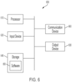
- Storage 640 can be any suitable device that provides storage, such as an electrical, magnetic, or optical memory including a RAM, cache, hard drive, removable storage disk, or other non-transitory computer readable medium.
- Communication device 660 can include any suitable device or combination of devices capable of transmitting and receiving signals from one or more other computing systems or modules.
- the components of the computing system 600 can be connected in any suitable manner, such as via a physical bus or wirelessly.
- Processor(s) 610 can be any suitable processor or combination of processors, including any of, or any combination of, a central processing unit (CPU), graphics processing unit (GPU), field programmable gate array (FPGA), and application-specific integrated circuit (ASIC).
- Software 650 which can be stored in storage 640 and executed by one or more processors 610, can include, for example, the programming that embodies the functionality or portions of the functionality of the present disclosure (e.g., as embodied in the devices as described above).
- software 650 can include one or more programs for execution by one or more processor(s) 610 for performing one or more of the steps of the methods described herein, such as one or more steps of method 300 of FIG. 3 .
Landscapes
- Engineering & Computer Science (AREA)
- Aviation & Aerospace Engineering (AREA)
- Mechanical Engineering (AREA)
- Life Sciences & Earth Sciences (AREA)
- Transportation (AREA)
- Power Engineering (AREA)
- Sustainable Energy (AREA)
- Sustainable Development (AREA)
- General Physics & Mathematics (AREA)
- Automation & Control Theory (AREA)
- Physics & Mathematics (AREA)
- Remote Sensing (AREA)
- Radar, Positioning & Navigation (AREA)
- Chemical & Material Sciences (AREA)
- Combustion & Propulsion (AREA)
- Charge And Discharge Circuits For Batteries Or The Like (AREA)
- Details Of Aerials (AREA)
- Control Of Multiple Motors (AREA)
- Transmission Devices (AREA)
- Control Of Position, Course, Altitude, Or Attitude Of Moving Bodies (AREA)
- Remote Monitoring And Control Of Power-Distribution Networks (AREA)
- Feedback Control In General (AREA)
Claims (14)
- Verfahren zum Steuern eines elektrischen Luftfahrzeugs (100), das eine Vielzahl von Aktuatoren umfasst, die eine Vielzahl von elektrischen Antriebseinheiten (112, 114) enthalten, wobei das Verfahren Folgendes umfasst:Empfangen (302) gewünschter Kraft- und Momentenbefehle (408) für das elektrische Luftfahrzeug;Bestimmen (304) von Steuerbefehlen für die Vielzahl von Aktuatoren basierend auf den gewünschten Kraft- und Momentenbefehlen durch Lösen eines Optimierungsproblems, das einen Geräuschminimierungsterm zum Minimieren eines durch die elektrischen Antriebseinheiten erzeugten Geräusches umfasst; undSteuern (310) der Vielzahl von Aktuatoren gemäß den bestimmten Steuerbefehlen, um die Kraft- und Momentenbefehle für das elektrische Luftfahrzeug zu erfüllen,wobei mindestens ein Teil der Vielzahl von elektrischen Antriebseinheiten neigbar ist, dadurch gekennzeichnet, dassdas Steuern der Vielzahl von Aktuatoren gemäß den bestimmten Steuerbefehlen mindestens eines von Neigen der elektrischen Antriebseinheiten und Anpassen einer Lage des elektrischen Luftfahrzeugs, um die Hochkantflugzeit zu minimieren, umfasst.
- Verfahren nach Anspruch 1, wobei das Steuern der Vielzahl von Aktuatoren gemäß den bestimmten Steuerbefehlen Betreiben von mindestens einer ersten elektrischen Antriebseinheit der Vielzahl von elektrischen Antriebseinheiten mit einer anderen Geschwindigkeit als mindestens eine zweite elektrische Antriebseinheit der Vielzahl von elektrischen Antriebseinheiten, um Frequenzen der Vielzahl von elektrischen Antriebseinheiten über ein breiteres Frequenzband zu verteilen, umfasst.
- Verfahren nach Anspruch 2, wobei elektrische Antriebseinheiten, die sich näher an einem Rumpf (102) des elektrischen Luftfahrzeugs befinden, mit niedrigeren Geschwindigkeiten betrieben werden als elektrische Antriebseinheiten, die weiter von dem Rumpf entfernt sind, um ein Geräusch an dem Rumpf zu verringern.
- Verfahren nach Anspruch 2 oder Anspruch 3, wobei elektrische Antriebseinheiten während des Geradeausflugs mit unterschiedlichen Geschwindigkeiten betrieben werden.
- Verfahren nach einem der vorhergehenden Ansprüche, wobei das Steuern der Vielzahl von Aktuatoren gemäß den bestimmten Steuerbefehlen Einstellen einer Steigung der Blätter von mindestens einer elektrischen Antriebseinheit (116, 120) umfasst, um eine Geschwindigkeit der mindestens einen elektrischen Antriebseinheit zu minimieren.
- Verfahren nach einem der vorhergehenden Ansprüche, wobei das elektrische Luftfahrzeug ein senkrecht startendes und landendes Luftfahrzeug ist.
- Verfahren nach einem der vorhergehenden Ansprüche, wobei das elektrische Luftfahrzeug bemannt ist.
- Verfahren nach einem der vorhergehenden Ansprüche, wobei das elektrische Luftfahrzeug mehrere elektrische Antriebseinheiten auf beiden Seiten eines Rumpfs des elektrischen Luftfahrzeugs umfasst.
- System zum Steuern eines elektrischen Luftfahrzeugs, das eine Vielzahl von Aktuatoren umfasst, die eine Vielzahl von elektrischen Antriebseinheiten enthalten, wobei das System Folgendes umfasst:einen oder mehrere Prozessoren (610),einen Speicher (640) undein oder mehrere Programme (650), die in dem Speicher zur Ausführung durch den einen oder die mehreren Prozessoren gespeichert sind, um zu bewirken, dass das System das Verfahren nach einem der vorhergehenden Ansprüche durchführt.
- Elektrisches Luftfahrzeug, umfassend:eine Vielzahl von Aktuatoren, die eine Vielzahl von elektrischen Antriebseinheiten enthält; unddas System nach Anspruch 9 zum Steuern des elektrischen Luftfahrzeugs über die Vielzahl von Aktuatoren.
- Elektrisches Luftfahrzeug nach Anspruch 10, wobei mindestens ein Teil der Vielzahl von elektrischen Antriebseinheiten neigbar ist.
- Elektrisches Luftfahrzeug nach Anspruch 10 oder 11, wobei das elektrische Luftfahrzeug ein senkrecht startendes und landendes Luftfahrzeug ist.
- Elektrisches Luftfahrzeug nach einem der Ansprüche 10-12, wobei das elektrische Luftfahrzeug bemannt ist.
- Elektrisches Luftfahrzeug nach einem der Ansprüche 10-13, mehrere elektrische Antriebseinheiten auf beiden Seiten eines Rumpfs (102) des elektrischen Luftfahrzeugs umfassend.
Priority Applications (1)
| Application Number | Priority Date | Filing Date | Title |
|---|---|---|---|
| EP23220866.0A EP4324745A3 (de) | 2021-01-25 | 2022-01-24 | Systeme und verfahren zur steuerung eines elektrischen vertikal startenden und landenden flugzeugs |
Applications Claiming Priority (2)
| Application Number | Priority Date | Filing Date | Title |
|---|---|---|---|
| US17/157,580 US11945597B2 (en) | 2021-01-25 | 2021-01-25 | Systems and methods for control allocation for electric vertical take-off and landing aircraft |
| PCT/US2022/070303 WO2022159975A1 (en) | 2021-01-25 | 2022-01-24 | Systems and methods for controlling an electric vertical take-off and landing aircraft |
Related Child Applications (2)
| Application Number | Title | Priority Date | Filing Date |
|---|---|---|---|
| EP23220866.0A Division EP4324745A3 (de) | 2021-01-25 | 2022-01-24 | Systeme und verfahren zur steuerung eines elektrischen vertikal startenden und landenden flugzeugs |
| EP23220866.0A Division-Into EP4324745A3 (de) | 2021-01-25 | 2022-01-24 | Systeme und verfahren zur steuerung eines elektrischen vertikal startenden und landenden flugzeugs |
Publications (3)
| Publication Number | Publication Date |
|---|---|
| EP4281365A1 EP4281365A1 (de) | 2023-11-29 |
| EP4281365C0 EP4281365C0 (de) | 2024-07-03 |
| EP4281365B1 true EP4281365B1 (de) | 2024-07-03 |
Family
ID=80445720
Family Applications (2)
| Application Number | Title | Priority Date | Filing Date |
|---|---|---|---|
| EP22703539.1A Active EP4281365B1 (de) | 2021-01-25 | 2022-01-24 | Systeme und verfahren zur steuerung eines elektrischen senkrecht startenden und landenden flugzeugs |
| EP23220866.0A Pending EP4324745A3 (de) | 2021-01-25 | 2022-01-24 | Systeme und verfahren zur steuerung eines elektrischen vertikal startenden und landenden flugzeugs |
Family Applications After (1)
| Application Number | Title | Priority Date | Filing Date |
|---|---|---|---|
| EP23220866.0A Pending EP4324745A3 (de) | 2021-01-25 | 2022-01-24 | Systeme und verfahren zur steuerung eines elektrischen vertikal startenden und landenden flugzeugs |
Country Status (9)
| Country | Link |
|---|---|
| US (2) | US11945597B2 (de) |
| EP (2) | EP4281365B1 (de) |
| JP (2) | JP7660209B2 (de) |
| KR (2) | KR102860909B1 (de) |
| CN (2) | CN118220497A (de) |
| AU (2) | AU2022211444B2 (de) |
| CA (2) | CA3206218A1 (de) |
| ES (1) | ES2984856T3 (de) |
| WO (1) | WO2022159975A1 (de) |
Families Citing this family (14)
| Publication number | Priority date | Publication date | Assignee | Title |
|---|---|---|---|---|
| US10618656B2 (en) * | 2017-10-04 | 2020-04-14 | Textron Innovations Inc. | Tiltrotor aircraft having interchangeable payload modules |
| US11453513B2 (en) * | 2018-04-26 | 2022-09-27 | Skydio, Inc. | Autonomous aerial vehicle hardware configuration |
| US20210362849A1 (en) | 2020-05-19 | 2021-11-25 | Archer Aviation, Inc. | Vertical take-off and landing aircraft |
| DE102021102251A1 (de) * | 2021-02-01 | 2022-08-04 | Volocopter Gmbh | Verfahren und Steuereinheit zum Steuern eines überbestimmten Systems, System und Luftfahrzeug |
| US11919631B2 (en) | 2021-02-08 | 2024-03-05 | Archer Aviation, Inc. | Vertical take-off and landing aircraft with aft rotor tilting |
| US12344390B2 (en) * | 2021-03-10 | 2025-07-01 | Textron Innovations Inc. | Method of adjusting directional movement ability in a multi-rotor aircraft |
| US11435762B1 (en) * | 2021-08-17 | 2022-09-06 | Beta Air, Llc | System and method for the autonomous transition of an electric vertical takeoff and landing aircraft |
| MX2024004577A (es) * | 2021-10-15 | 2024-07-10 | Real Time Robotics Inc | Un multicoptero. |
| US11562653B1 (en) * | 2021-11-17 | 2023-01-24 | Beta Air, Llc | Systems and methods for in-flight re-routing of an electric aircraft |
| JP7735201B2 (ja) * | 2022-02-22 | 2025-09-08 | 本田技研工業株式会社 | 姿勢制御装置 |
| USD1067164S1 (en) | 2022-08-05 | 2025-03-18 | Archer Aviation, Inc. | Aircraft |
| USD1087851S1 (en) | 2022-09-19 | 2025-08-12 | Wisk Aero Llc | Interior of an autonomous aircraft |
| CN121752968A (zh) * | 2023-07-10 | 2026-03-27 | 阿切尔航空公司 | 用于航空器的飞行控制的系统和方法 |
| GB2642543A (en) | 2024-07-12 | 2026-01-14 | Vertical Aerospace Group Ltd | Propellers |
Family Cites Families (51)
| Publication number | Priority date | Publication date | Assignee | Title |
|---|---|---|---|---|
| US3059876A (en) * | 1958-07-03 | 1962-10-23 | Haviland H Platt | Vertical take-off airplane |
| US5001646A (en) | 1988-12-19 | 1991-03-19 | Mcdonnell Douglas Corporation | Automated helicopter flight control system |
| US6344700B1 (en) | 1999-10-01 | 2002-02-05 | Bell Helicopter Textron Inc. | Redundant electrical DC power system for aircraft |
| JP2003533404A (ja) | 2000-05-16 | 2003-11-11 | ベル ヘリコプター テクストロン インコーポレイテッド | エンベローププロテクションを統合したマルチモードのティルトローターナセル制御システム |
| US6655631B2 (en) * | 2000-07-28 | 2003-12-02 | John Frederick Austen-Brown | Personal hoverplane with four tiltmotors |
| DE10212036B4 (de) * | 2002-03-19 | 2009-01-02 | Eads Deutschland Gmbh | Verfahren zur Geräuschreduktion für mehrmotorige Propellerflugzeuge |
| US6885917B2 (en) | 2002-11-07 | 2005-04-26 | The Boeing Company | Enhanced flight control systems and methods for a jet powered tri-mode aircraft |
| US7861967B2 (en) * | 2008-04-25 | 2011-01-04 | Abe Karem | Aircraft with integrated lift and propulsion system |
| WO2008065664A2 (en) | 2006-11-30 | 2008-06-05 | Urban Aeronautics Ltd. | Flight control cockpit modes in ducted fan vtol vehicles |
| DE102010021022A1 (de) | 2010-05-19 | 2011-11-24 | Eads Deutschland Gmbh | Kippflügel-Flugzeug |
| US9162752B2 (en) | 2011-07-15 | 2015-10-20 | Bell Helicopter Textron Inc. | Flight control laws for automatic hover hold |
| US9411329B2 (en) * | 2011-11-15 | 2016-08-09 | Palo Alto Research Center Incorporated | Hierarchical model communication and control in a managed electrical system |
| US9694911B2 (en) * | 2014-03-18 | 2017-07-04 | Joby Aviation, Inc. | Aerodynamically efficient lightweight vertical take-off and landing aircraft with pivoting rotors and stowing rotor blades |
| CA2996844A1 (en) * | 2014-08-29 | 2016-06-16 | Tzunum, Inc. | Power train for a hybrid-electric aircraft |
| US9415870B1 (en) | 2015-09-02 | 2016-08-16 | Amazon Technologies, Inc. | Unmanned aerial vehicle motor driving randomization and feedback for noise abatement |
| RU2018143894A (ru) * | 2016-05-18 | 2020-06-18 | А^3 Бай Эйрбас Ллк | Самопилотируемый летательный аппарат для пассажирских и грузовых перевозок |
| WO2018064209A1 (en) | 2016-09-28 | 2018-04-05 | Kitty Hawk Corporation | Tilt-wing aircraft |
| US10364036B2 (en) * | 2016-10-18 | 2019-07-30 | Kitty Hawk Corporation | Multicopter with boom-mounted rotors |
| US10370099B2 (en) * | 2016-10-18 | 2019-08-06 | Kitty Hawk Corporation | Online optimization-based flight control system |
| US9898033B1 (en) | 2016-12-08 | 2018-02-20 | Kitty Hawk Corporation | Magnetic spring inceptor |
| US10536078B2 (en) * | 2017-05-04 | 2020-01-14 | Amazon Technologies, Inc. | Hysteresis-controlled DC-DC boost converter for aerial vehicles |
| US10435148B2 (en) * | 2017-05-08 | 2019-10-08 | Aurora Flight Sciences Corporation | Systems and methods for acoustic radiation control |
| CA3063192A1 (en) * | 2017-05-10 | 2018-11-15 | Embry-Riddle Aeronautical University, Inc. | Systems and methods for noise mitigation for hybrid and electric aircraft |
| CN111051201A (zh) | 2017-06-30 | 2020-04-21 | 空中客车A^3有限责任公司 | 用于飞行器的故障容限电气系统 |
| US10618656B2 (en) * | 2017-10-04 | 2020-04-14 | Textron Innovations Inc. | Tiltrotor aircraft having interchangeable payload modules |
| US11008093B2 (en) * | 2018-03-22 | 2021-05-18 | Aurora Flight Sciences Corporation | Systems and methods for reducing the propeller noise |
| US10935985B2 (en) | 2018-04-25 | 2021-03-02 | The Boeing Company | Pitch and thrust control for tilt-rotor aircraft |
| US11091260B2 (en) * | 2018-04-27 | 2021-08-17 | Wing Aviation Llc | Counter-rotating propellers for aerial vehicle |
| US12006048B2 (en) | 2018-05-31 | 2024-06-11 | Joby Aero, Inc. | Electric power system architecture and fault tolerant VTOL aircraft using same |
| EP3803132B1 (de) | 2018-06-01 | 2025-08-27 | Joby Aero, Inc. | System zur geräuschminderung von flugzeugen |
| DE102018118437A1 (de) * | 2018-07-31 | 2020-02-06 | Airbus Defence and Space GmbH | System und Verfahren zum Überwachen des Zustands eines unbemannten Luftfahrzeugs |
| US11198515B2 (en) | 2018-09-11 | 2021-12-14 | Embraer S.A. | Method and system for distributed electrical loads connected to shared power sources |
| EP3656669B1 (de) * | 2018-11-26 | 2021-01-13 | AIRBUS HELICOPTERS DEUTSCHLAND GmbH | Senkrecht startendes und landendes multirotorflugzeug mit mindestens acht schuberzeugungseinheiten |
| US10983534B2 (en) | 2018-12-07 | 2021-04-20 | Joby Aero, Inc. | Aircraft control system and method |
| US11254219B2 (en) * | 2019-03-25 | 2022-02-22 | Beta Air, Llc | Systems and methods for maintaining attitude control under degraded energy source conditions using multiple propulsors |
| WO2020240567A1 (en) | 2019-05-28 | 2020-12-03 | Eviation Aircraft Ltd. | Thrust control system and method |
| US11420735B2 (en) * | 2019-06-14 | 2022-08-23 | Textron Innovations Inc. | Multi-rotor noise control by automated distribution propulsion |
| DE102019214343A1 (de) | 2019-09-20 | 2021-03-25 | Robert Bosch Gmbh | Verfahren zum Ausgleichen von Ladezuständen eines elektrischen Energiespeichers |
| EP3848287A1 (de) | 2020-01-07 | 2021-07-14 | Hamilton Sundstrand Corporation | Elektrisches antriebssystem |
| US11554865B2 (en) * | 2020-02-18 | 2023-01-17 | Aurora Flight Sciences Corporation | Vertical take-off and landing (VTOL) aircraft and related methods |
| US11155356B2 (en) | 2020-02-19 | 2021-10-26 | Kitty Hawk Corporation | Thrust allocation using optimization in a distributed flight control system |
| EP4157717A4 (de) | 2020-05-29 | 2024-05-29 | Flightwave Aerospace Systems | Schubvektorisierungssystem und verfahren zur verwendung mit unbemannten luftfahrzeugen |
| DE102020209359A1 (de) | 2020-07-24 | 2022-01-27 | Robert Bosch Gesellschaft mit beschränkter Haftung | Kurz- oder senkrechtstartfähiges Fluggerät, Leistungselektronik und Verfahren zum Betreiben des Fluggeräts |
| US11495982B2 (en) | 2020-08-31 | 2022-11-08 | The Boeing Company | System and method for allocating propulsion load power drawn from high-energy and high-power batteries |
| US12227290B2 (en) | 2020-10-27 | 2025-02-18 | Wisk Aero Llc | Power distribution circuits for electrically powered aircraft |
| US11919631B2 (en) | 2021-02-08 | 2024-03-05 | Archer Aviation, Inc. | Vertical take-off and landing aircraft with aft rotor tilting |
| US20220289395A1 (en) | 2021-03-09 | 2022-09-15 | Honda Motor Co., Ltd. | Propulsion system for aircraft and method of manufacturing aircraft |
| US11524767B2 (en) | 2021-03-31 | 2022-12-13 | Beta Air, Llc | Methods and systems for flight control configured for use in an electric aircraft |
| CN113002784A (zh) | 2021-04-06 | 2021-06-22 | 广东汇天航空航天科技有限公司 | 电动载人飞行器的动力装置和电动载人飞行器 |
| CN215475774U (zh) | 2021-04-06 | 2022-01-11 | 广东汇天航空航天科技有限公司 | 电动载人飞行器的动力装置和电动载人飞行器 |
| US11435761B1 (en) | 2021-07-23 | 2022-09-06 | Beta Air, Llc | System and method for distributed flight control system for an electric vehicle |
-
2021
- 2021-01-25 US US17/157,580 patent/US11945597B2/en active Active
-
2022
- 2022-01-24 KR KR1020247027355A patent/KR102860909B1/ko active Active
- 2022-01-24 JP JP2023544754A patent/JP7660209B2/ja active Active
- 2022-01-24 EP EP22703539.1A patent/EP4281365B1/de active Active
- 2022-01-24 CN CN202410408459.9A patent/CN118220497A/zh active Pending
- 2022-01-24 ES ES22703539T patent/ES2984856T3/es active Active
- 2022-01-24 CA CA3206218A patent/CA3206218A1/en active Pending
- 2022-01-24 WO PCT/US2022/070303 patent/WO2022159975A1/en not_active Ceased
- 2022-01-24 EP EP23220866.0A patent/EP4324745A3/de active Pending
- 2022-01-24 KR KR1020237028439A patent/KR102861159B1/ko active Active
- 2022-01-24 AU AU2022211444A patent/AU2022211444B2/en active Active
- 2022-01-24 CA CA3285939A patent/CA3285939A1/en active Pending
- 2022-01-24 CN CN202280019988.9A patent/CN117062751B/zh active Active
-
2023
- 2023-12-28 US US18/398,577 patent/US12291343B2/en active Active
-
2024
- 2024-04-10 AU AU2024202298A patent/AU2024202298B2/en active Active
- 2024-06-06 JP JP2024092378A patent/JP7675262B2/ja active Active
Also Published As
| Publication number | Publication date |
|---|---|
| CA3285939A1 (en) | 2025-10-28 |
| JP7675262B2 (ja) | 2025-05-12 |
| AU2022211444A9 (en) | 2024-09-26 |
| CN118220497A (zh) | 2024-06-21 |
| AU2022211444A1 (en) | 2023-08-17 |
| JP7660209B2 (ja) | 2025-04-10 |
| JP2024116265A (ja) | 2024-08-27 |
| EP4324745A3 (de) | 2024-05-15 |
| AU2022211444B2 (en) | 2024-06-13 |
| US20240132224A1 (en) | 2024-04-25 |
| WO2022159975A1 (en) | 2022-07-28 |
| CN117062751B (zh) | 2025-09-26 |
| EP4281365C0 (de) | 2024-07-03 |
| NZ813595A (en) | 2025-08-29 |
| KR102860909B1 (ko) | 2025-09-18 |
| KR20230175179A (ko) | 2023-12-29 |
| CN117062751A (zh) | 2023-11-14 |
| AU2024202298A1 (en) | 2024-05-02 |
| KR102861159B1 (ko) | 2025-09-18 |
| US11945597B2 (en) | 2024-04-02 |
| KR20240128137A (ko) | 2024-08-23 |
| CA3206218A1 (en) | 2022-07-28 |
| NZ802368A (en) | 2025-05-30 |
| US12291343B2 (en) | 2025-05-06 |
| EP4281365A1 (de) | 2023-11-29 |
| ES2984856T3 (es) | 2024-10-31 |
| JP2024506816A (ja) | 2024-02-15 |
| EP4324745A2 (de) | 2024-02-21 |
| US20220234747A1 (en) | 2022-07-28 |
| AU2024202298B2 (en) | 2025-04-10 |
Similar Documents
| Publication | Publication Date | Title |
|---|---|---|
| EP4281365B1 (de) | Systeme und verfahren zur steuerung eines elektrischen senkrecht startenden und landenden flugzeugs | |
| WO2019070752A1 (en) | AUTONOMOUS FLIGHT AMBULANCE | |
| CN110466752B (zh) | 一种倾转旋翼无人机的控制方法及倾转旋翼无人机 | |
| EP4345001B1 (de) | Luftfahrzeug und steuerungsverfahren und -vorrichtung dafür sowie speichermedium | |
| US20250074582A1 (en) | Aircraft, aircraft control method and device, and computer-readable storage medium | |
| US9944388B2 (en) | Rotorcraft state control | |
| US12164311B1 (en) | Systems and methods for applying a movable notch filter in flight control of EVTOL aircraft | |
| US20240326988A1 (en) | Systems and methods for active control of aircraft's center of gravity | |
| US12377999B2 (en) | Systems and methods for vibration attenuation in flight control of an aircraft | |
| HK40101286A (en) | Systems and methods for controlling an electric vertical take-off and landing aircraft | |
| HK40101286B (en) | Systems and methods for controlling an electric vertical take-off and landing aircraft | |
| HK40098578A (en) | Systems and methods for controlling an electric vertical take-off and landing aircraft | |
| EP4719907A2 (de) | Systeme und verfahren zur flugzeuglastminderung | |
| WO2025042458A2 (en) | Systems and methods for vibration attenuation in flight control of an aircraft | |
| Liu et al. | Active aerodynamic enhancement control for hybrid quadrotors with moving wings | |
| KR20260035830A (ko) | 항공기 비행 제어를 위한 시스템 및 방법 | |
| CN121693710A (zh) | 用于航空器功能优先级排序和分配的系统和方法 |
Legal Events
| Date | Code | Title | Description |
|---|---|---|---|
| STAA | Information on the status of an ep patent application or granted ep patent |
Free format text: STATUS: UNKNOWN |
|
| STAA | Information on the status of an ep patent application or granted ep patent |
Free format text: STATUS: THE INTERNATIONAL PUBLICATION HAS BEEN MADE |
|
| PUAI | Public reference made under article 153(3) epc to a published international application that has entered the european phase |
Free format text: ORIGINAL CODE: 0009012 |
|
| STAA | Information on the status of an ep patent application or granted ep patent |
Free format text: STATUS: REQUEST FOR EXAMINATION WAS MADE |
|
| 17P | Request for examination filed |
Effective date: 20230818 |
|
| AK | Designated contracting states |
Kind code of ref document: A1 Designated state(s): AL AT BE BG CH CY CZ DE DK EE ES FI FR GB GR HR HU IE IS IT LI LT LU LV MC MK MT NL NO PL PT RO RS SE SI SK SM TR |
|
| GRAP | Despatch of communication of intention to grant a patent |
Free format text: ORIGINAL CODE: EPIDOSNIGR1 |
|
| STAA | Information on the status of an ep patent application or granted ep patent |
Free format text: STATUS: GRANT OF PATENT IS INTENDED |
|
| DAV | Request for validation of the european patent (deleted) | ||
| DAX | Request for extension of the european patent (deleted) | ||
| REG | Reference to a national code |
Ref country code: HK Ref legal event code: DE Ref document number: 40101286 Country of ref document: HK |
|
| INTG | Intention to grant announced |
Effective date: 20240416 |
|
| GRAS | Grant fee paid |
Free format text: ORIGINAL CODE: EPIDOSNIGR3 |
|
| GRAA | (expected) grant |
Free format text: ORIGINAL CODE: 0009210 |
|
| STAA | Information on the status of an ep patent application or granted ep patent |
Free format text: STATUS: THE PATENT HAS BEEN GRANTED |
|
| AK | Designated contracting states |
Kind code of ref document: B1 Designated state(s): AL AT BE BG CH CY CZ DE DK EE ES FI FR GB GR HR HU IE IS IT LI LT LU LV MC MK MT NL NO PL PT RO RS SE SI SK SM TR |
|
| REG | Reference to a national code |
Ref country code: CH Ref legal event code: EP |
|
| REG | Reference to a national code |
Ref country code: DE Ref legal event code: R096 Ref document number: 602022004349 Country of ref document: DE |
|
| U01 | Request for unitary effect filed |
Effective date: 20240726 |
|
| U07 | Unitary effect registered |
Designated state(s): AT BE BG DE DK EE FI FR IT LT LU LV MT NL PT SE SI Effective date: 20240809 |
|
| REG | Reference to a national code |
Ref country code: ES Ref legal event code: FG2A Ref document number: 2984856 Country of ref document: ES Kind code of ref document: T3 Effective date: 20241031 |
|
| U20 | Renewal fee for the european patent with unitary effect paid |
Year of fee payment: 4 Effective date: 20241205 |
|
| PG25 | Lapsed in a contracting state [announced via postgrant information from national office to epo] |
Ref country code: NO Free format text: LAPSE BECAUSE OF FAILURE TO SUBMIT A TRANSLATION OF THE DESCRIPTION OR TO PAY THE FEE WITHIN THE PRESCRIBED TIME-LIMIT Effective date: 20241003 |
|
| PG25 | Lapsed in a contracting state [announced via postgrant information from national office to epo] |
Ref country code: PL Free format text: LAPSE BECAUSE OF FAILURE TO SUBMIT A TRANSLATION OF THE DESCRIPTION OR TO PAY THE FEE WITHIN THE PRESCRIBED TIME-LIMIT Effective date: 20240703 Ref country code: GR Free format text: LAPSE BECAUSE OF FAILURE TO SUBMIT A TRANSLATION OF THE DESCRIPTION OR TO PAY THE FEE WITHIN THE PRESCRIBED TIME-LIMIT Effective date: 20241004 |
|
| PG25 | Lapsed in a contracting state [announced via postgrant information from national office to epo] |
Ref country code: IS Free format text: LAPSE BECAUSE OF FAILURE TO SUBMIT A TRANSLATION OF THE DESCRIPTION OR TO PAY THE FEE WITHIN THE PRESCRIBED TIME-LIMIT Effective date: 20241103 |
|
| PG25 | Lapsed in a contracting state [announced via postgrant information from national office to epo] |
Ref country code: CZ Free format text: LAPSE BECAUSE OF FAILURE TO SUBMIT A TRANSLATION OF THE DESCRIPTION OR TO PAY THE FEE WITHIN THE PRESCRIBED TIME-LIMIT Effective date: 20240703 Ref country code: HR Free format text: LAPSE BECAUSE OF FAILURE TO SUBMIT A TRANSLATION OF THE DESCRIPTION OR TO PAY THE FEE WITHIN THE PRESCRIBED TIME-LIMIT Effective date: 20240703 |
|
| PG25 | Lapsed in a contracting state [announced via postgrant information from national office to epo] |
Ref country code: RS Free format text: LAPSE BECAUSE OF FAILURE TO SUBMIT A TRANSLATION OF THE DESCRIPTION OR TO PAY THE FEE WITHIN THE PRESCRIBED TIME-LIMIT Effective date: 20241003 |
|
| PG25 | Lapsed in a contracting state [announced via postgrant information from national office to epo] |
Ref country code: RS Free format text: LAPSE BECAUSE OF FAILURE TO SUBMIT A TRANSLATION OF THE DESCRIPTION OR TO PAY THE FEE WITHIN THE PRESCRIBED TIME-LIMIT Effective date: 20241003 Ref country code: PL Free format text: LAPSE BECAUSE OF FAILURE TO SUBMIT A TRANSLATION OF THE DESCRIPTION OR TO PAY THE FEE WITHIN THE PRESCRIBED TIME-LIMIT Effective date: 20240703 Ref country code: NO Free format text: LAPSE BECAUSE OF FAILURE TO SUBMIT A TRANSLATION OF THE DESCRIPTION OR TO PAY THE FEE WITHIN THE PRESCRIBED TIME-LIMIT Effective date: 20241003 Ref country code: IS Free format text: LAPSE BECAUSE OF FAILURE TO SUBMIT A TRANSLATION OF THE DESCRIPTION OR TO PAY THE FEE WITHIN THE PRESCRIBED TIME-LIMIT Effective date: 20241103 Ref country code: HR Free format text: LAPSE BECAUSE OF FAILURE TO SUBMIT A TRANSLATION OF THE DESCRIPTION OR TO PAY THE FEE WITHIN THE PRESCRIBED TIME-LIMIT Effective date: 20240703 Ref country code: GR Free format text: LAPSE BECAUSE OF FAILURE TO SUBMIT A TRANSLATION OF THE DESCRIPTION OR TO PAY THE FEE WITHIN THE PRESCRIBED TIME-LIMIT Effective date: 20241004 Ref country code: CZ Free format text: LAPSE BECAUSE OF FAILURE TO SUBMIT A TRANSLATION OF THE DESCRIPTION OR TO PAY THE FEE WITHIN THE PRESCRIBED TIME-LIMIT Effective date: 20240703 |
|
| PG25 | Lapsed in a contracting state [announced via postgrant information from national office to epo] |
Ref country code: SM Free format text: LAPSE BECAUSE OF FAILURE TO SUBMIT A TRANSLATION OF THE DESCRIPTION OR TO PAY THE FEE WITHIN THE PRESCRIBED TIME-LIMIT Effective date: 20240703 |
|
| PG25 | Lapsed in a contracting state [announced via postgrant information from national office to epo] |
Ref country code: SK Free format text: LAPSE BECAUSE OF FAILURE TO SUBMIT A TRANSLATION OF THE DESCRIPTION OR TO PAY THE FEE WITHIN THE PRESCRIBED TIME-LIMIT Effective date: 20240703 |
|
| PLBE | No opposition filed within time limit |
Free format text: ORIGINAL CODE: 0009261 |
|
| STAA | Information on the status of an ep patent application or granted ep patent |
Free format text: STATUS: NO OPPOSITION FILED WITHIN TIME LIMIT |
|
| 26N | No opposition filed |
Effective date: 20250404 |
|
| PG25 | Lapsed in a contracting state [announced via postgrant information from national office to epo] |
Ref country code: MC Free format text: LAPSE BECAUSE OF FAILURE TO SUBMIT A TRANSLATION OF THE DESCRIPTION OR TO PAY THE FEE WITHIN THE PRESCRIBED TIME-LIMIT Effective date: 20240703 |
|
| PG25 | Lapsed in a contracting state [announced via postgrant information from national office to epo] |
Ref country code: IE Free format text: LAPSE BECAUSE OF NON-PAYMENT OF DUE FEES Effective date: 20250124 |
|
| REG | Reference to a national code |
Ref country code: CH Ref legal event code: R18 Free format text: ST27 STATUS EVENT CODE: U-0-0-R10-R18 (AS PROVIDED BY THE NATIONAL OFFICE) Effective date: 20260123 |
|
| REG | Reference to a national code |
Ref country code: CH Ref legal event code: U11 Free format text: ST27 STATUS EVENT CODE: U-0-0-U10-U11 (AS PROVIDED BY THE NATIONAL OFFICE) Effective date: 20260201 |
|
| U20 | Renewal fee for the european patent with unitary effect paid |
Year of fee payment: 5 Effective date: 20260108 |
|
| REG | Reference to a national code |
Ref country code: GB Ref legal event code: S117 Free format text: REQUEST FILED; REQUEST FOR CORRECTION UNDER SECTION 117 FILED ON 16 JANUARY 2026 Ref country code: GB Ref legal event code: S117 Free format text: CORRECTIONS ALLOWED; REQUEST FOR CORRECTION UNDER SECTION 117 FILED ON 16 JANUARY 2026 WAS ALLOWED ON 24 FEBRUARY 2026 |
|
| PGFP | Annual fee paid to national office [announced via postgrant information from national office to epo] |
Ref country code: GB Payment date: 20260108 Year of fee payment: 5 |
|
| PGFP | Annual fee paid to national office [announced via postgrant information from national office to epo] |
Ref country code: ES Payment date: 20260213 Year of fee payment: 5 |
|
| PG25 | Lapsed in a contracting state [announced via postgrant information from national office to epo] |
Ref country code: RO Free format text: LAPSE BECAUSE OF FAILURE TO SUBMIT A TRANSLATION OF THE DESCRIPTION OR TO PAY THE FEE WITHIN THE PRESCRIBED TIME-LIMIT Effective date: 20240703 |
|
| PGFP | Annual fee paid to national office [announced via postgrant information from national office to epo] |
Ref country code: CH Payment date: 20260201 Year of fee payment: 5 |