EP4281340B1 - Anhängersteuergerät - Google Patents
Anhängersteuergerät Download PDFInfo
- Publication number
- EP4281340B1 EP4281340B1 EP21824675.9A EP21824675A EP4281340B1 EP 4281340 B1 EP4281340 B1 EP 4281340B1 EP 21824675 A EP21824675 A EP 21824675A EP 4281340 B1 EP4281340 B1 EP 4281340B1
- Authority
- EP
- European Patent Office
- Prior art keywords
- trailer
- coupling force
- vehicle
- control
- brake system
- Prior art date
- Legal status (The legal status is an assumption and is not a legal conclusion. Google has not performed a legal analysis and makes no representation as to the accuracy of the status listed.)
- Active
Links
Images


Classifications
-
- B—PERFORMING OPERATIONS; TRANSPORTING
- B60—VEHICLES IN GENERAL
- B60T—VEHICLE BRAKE CONTROL SYSTEMS OR PARTS THEREOF; BRAKE CONTROL SYSTEMS OR PARTS THEREOF, IN GENERAL; ARRANGEMENT OF BRAKING ELEMENTS ON VEHICLES IN GENERAL; PORTABLE DEVICES FOR PREVENTING UNWANTED MOVEMENT OF VEHICLES; VEHICLE MODIFICATIONS TO FACILITATE COOLING OF BRAKES
- B60T8/00—Arrangements for adjusting wheel-braking force to meet varying vehicular or ground-surface conditions, e.g. limiting or varying distribution of braking force
- B60T8/17—Using electrical or electronic regulation means to control braking
- B60T8/1701—Braking or traction control means specially adapted for particular types of vehicles
- B60T8/1708—Braking or traction control means specially adapted for particular types of vehicles for lorries or tractor-trailer combinations
-
- B—PERFORMING OPERATIONS; TRANSPORTING
- B60—VEHICLES IN GENERAL
- B60Q—ARRANGEMENT OF SIGNALLING OR LIGHTING DEVICES, THE MOUNTING OR SUPPORTING THEREOF OR CIRCUITS THEREFOR, FOR VEHICLES IN GENERAL
- B60Q9/00—Arrangement or adaptation of signal devices not provided for in one of main groups B60Q1/00 - B60Q7/00, e.g. haptic signalling
-
- B—PERFORMING OPERATIONS; TRANSPORTING
- B60—VEHICLES IN GENERAL
- B60T—VEHICLE BRAKE CONTROL SYSTEMS OR PARTS THEREOF; BRAKE CONTROL SYSTEMS OR PARTS THEREOF, IN GENERAL; ARRANGEMENT OF BRAKING ELEMENTS ON VEHICLES IN GENERAL; PORTABLE DEVICES FOR PREVENTING UNWANTED MOVEMENT OF VEHICLES; VEHICLE MODIFICATIONS TO FACILITATE COOLING OF BRAKES
- B60T13/00—Transmitting braking action from initiating means to ultimate brake actuator with power assistance or drive; Brake systems incorporating such transmitting means, e.g. air-pressure brake systems
- B60T13/02—Transmitting braking action from initiating means to ultimate brake actuator with power assistance or drive; Brake systems incorporating such transmitting means, e.g. air-pressure brake systems with mechanical assistance or drive
- B60T13/06—Transmitting braking action from initiating means to ultimate brake actuator with power assistance or drive; Brake systems incorporating such transmitting means, e.g. air-pressure brake systems with mechanical assistance or drive by inertia, e.g. flywheel
- B60T13/08—Overrun brakes
-
- B—PERFORMING OPERATIONS; TRANSPORTING
- B60—VEHICLES IN GENERAL
- B60T—VEHICLE BRAKE CONTROL SYSTEMS OR PARTS THEREOF; BRAKE CONTROL SYSTEMS OR PARTS THEREOF, IN GENERAL; ARRANGEMENT OF BRAKING ELEMENTS ON VEHICLES IN GENERAL; PORTABLE DEVICES FOR PREVENTING UNWANTED MOVEMENT OF VEHICLES; VEHICLE MODIFICATIONS TO FACILITATE COOLING OF BRAKES
- B60T13/00—Transmitting braking action from initiating means to ultimate brake actuator with power assistance or drive; Brake systems incorporating such transmitting means, e.g. air-pressure brake systems
- B60T13/10—Transmitting braking action from initiating means to ultimate brake actuator with power assistance or drive; Brake systems incorporating such transmitting means, e.g. air-pressure brake systems with fluid assistance, drive, or release
- B60T13/12—Transmitting braking action from initiating means to ultimate brake actuator with power assistance or drive; Brake systems incorporating such transmitting means, e.g. air-pressure brake systems with fluid assistance, drive, or release the fluid being liquid
-
- B—PERFORMING OPERATIONS; TRANSPORTING
- B60—VEHICLES IN GENERAL
- B60T—VEHICLE BRAKE CONTROL SYSTEMS OR PARTS THEREOF; BRAKE CONTROL SYSTEMS OR PARTS THEREOF, IN GENERAL; ARRANGEMENT OF BRAKING ELEMENTS ON VEHICLES IN GENERAL; PORTABLE DEVICES FOR PREVENTING UNWANTED MOVEMENT OF VEHICLES; VEHICLE MODIFICATIONS TO FACILITATE COOLING OF BRAKES
- B60T13/00—Transmitting braking action from initiating means to ultimate brake actuator with power assistance or drive; Brake systems incorporating such transmitting means, e.g. air-pressure brake systems
- B60T13/10—Transmitting braking action from initiating means to ultimate brake actuator with power assistance or drive; Brake systems incorporating such transmitting means, e.g. air-pressure brake systems with fluid assistance, drive, or release
- B60T13/24—Transmitting braking action from initiating means to ultimate brake actuator with power assistance or drive; Brake systems incorporating such transmitting means, e.g. air-pressure brake systems with fluid assistance, drive, or release the fluid being gaseous
- B60T13/26—Compressed-air systems
- B60T13/261—Compressed-air systems systems with both indirect application and application by springs or weights and released by compressed air
- B60T13/263—Compressed-air systems systems with both indirect application and application by springs or weights and released by compressed air specially adapted for coupling with dependent systems, e.g. tractor-trailer systems
-
- B—PERFORMING OPERATIONS; TRANSPORTING
- B60—VEHICLES IN GENERAL
- B60T—VEHICLE BRAKE CONTROL SYSTEMS OR PARTS THEREOF; BRAKE CONTROL SYSTEMS OR PARTS THEREOF, IN GENERAL; ARRANGEMENT OF BRAKING ELEMENTS ON VEHICLES IN GENERAL; PORTABLE DEVICES FOR PREVENTING UNWANTED MOVEMENT OF VEHICLES; VEHICLE MODIFICATIONS TO FACILITATE COOLING OF BRAKES
- B60T13/00—Transmitting braking action from initiating means to ultimate brake actuator with power assistance or drive; Brake systems incorporating such transmitting means, e.g. air-pressure brake systems
- B60T13/10—Transmitting braking action from initiating means to ultimate brake actuator with power assistance or drive; Brake systems incorporating such transmitting means, e.g. air-pressure brake systems with fluid assistance, drive, or release
- B60T13/66—Electrical control in fluid-pressure brake systems
- B60T13/662—Electrical control in fluid-pressure brake systems characterised by specified functions of the control system components
-
- B—PERFORMING OPERATIONS; TRANSPORTING
- B60—VEHICLES IN GENERAL
- B60T—VEHICLE BRAKE CONTROL SYSTEMS OR PARTS THEREOF; BRAKE CONTROL SYSTEMS OR PARTS THEREOF, IN GENERAL; ARRANGEMENT OF BRAKING ELEMENTS ON VEHICLES IN GENERAL; PORTABLE DEVICES FOR PREVENTING UNWANTED MOVEMENT OF VEHICLES; VEHICLE MODIFICATIONS TO FACILITATE COOLING OF BRAKES
- B60T13/00—Transmitting braking action from initiating means to ultimate brake actuator with power assistance or drive; Brake systems incorporating such transmitting means, e.g. air-pressure brake systems
- B60T13/10—Transmitting braking action from initiating means to ultimate brake actuator with power assistance or drive; Brake systems incorporating such transmitting means, e.g. air-pressure brake systems with fluid assistance, drive, or release
- B60T13/66—Electrical control in fluid-pressure brake systems
- B60T13/68—Electrical control in fluid-pressure brake systems by electrically-controlled valves
-
- B—PERFORMING OPERATIONS; TRANSPORTING
- B60—VEHICLES IN GENERAL
- B60T—VEHICLE BRAKE CONTROL SYSTEMS OR PARTS THEREOF; BRAKE CONTROL SYSTEMS OR PARTS THEREOF, IN GENERAL; ARRANGEMENT OF BRAKING ELEMENTS ON VEHICLES IN GENERAL; PORTABLE DEVICES FOR PREVENTING UNWANTED MOVEMENT OF VEHICLES; VEHICLE MODIFICATIONS TO FACILITATE COOLING OF BRAKES
- B60T17/00—Component parts, details, or accessories of power brake systems not covered by groups B60T8/00, B60T13/00 or B60T15/00, or presenting other characteristic features
- B60T17/18—Safety devices; Monitoring
- B60T17/22—Devices for monitoring or checking brake systems; Signal devices
-
- B—PERFORMING OPERATIONS; TRANSPORTING
- B60—VEHICLES IN GENERAL
- B60T—VEHICLE BRAKE CONTROL SYSTEMS OR PARTS THEREOF; BRAKE CONTROL SYSTEMS OR PARTS THEREOF, IN GENERAL; ARRANGEMENT OF BRAKING ELEMENTS ON VEHICLES IN GENERAL; PORTABLE DEVICES FOR PREVENTING UNWANTED MOVEMENT OF VEHICLES; VEHICLE MODIFICATIONS TO FACILITATE COOLING OF BRAKES
- B60T7/00—Brake-action initiating means
- B60T7/12—Brake-action initiating means for automatic initiation; for initiation not subject to will of driver or passenger
- B60T7/20—Brake-action initiating means for automatic initiation; for initiation not subject to will of driver or passenger specially for trailers, e.g. in case of uncoupling of or overrunning by trailer
-
- B—PERFORMING OPERATIONS; TRANSPORTING
- B60—VEHICLES IN GENERAL
- B60T—VEHICLE BRAKE CONTROL SYSTEMS OR PARTS THEREOF; BRAKE CONTROL SYSTEMS OR PARTS THEREOF, IN GENERAL; ARRANGEMENT OF BRAKING ELEMENTS ON VEHICLES IN GENERAL; PORTABLE DEVICES FOR PREVENTING UNWANTED MOVEMENT OF VEHICLES; VEHICLE MODIFICATIONS TO FACILITATE COOLING OF BRAKES
- B60T8/00—Arrangements for adjusting wheel-braking force to meet varying vehicular or ground-surface conditions, e.g. limiting or varying distribution of braking force
- B60T8/17—Using electrical or electronic regulation means to control braking
- B60T8/1701—Braking or traction control means specially adapted for particular types of vehicles
-
- B—PERFORMING OPERATIONS; TRANSPORTING
- B60—VEHICLES IN GENERAL
- B60T—VEHICLE BRAKE CONTROL SYSTEMS OR PARTS THEREOF; BRAKE CONTROL SYSTEMS OR PARTS THEREOF, IN GENERAL; ARRANGEMENT OF BRAKING ELEMENTS ON VEHICLES IN GENERAL; PORTABLE DEVICES FOR PREVENTING UNWANTED MOVEMENT OF VEHICLES; VEHICLE MODIFICATIONS TO FACILITATE COOLING OF BRAKES
- B60T8/00—Arrangements for adjusting wheel-braking force to meet varying vehicular or ground-surface conditions, e.g. limiting or varying distribution of braking force
- B60T8/17—Using electrical or electronic regulation means to control braking
- B60T8/171—Detecting parameters used in the regulation; Measuring values used in the regulation
-
- B—PERFORMING OPERATIONS; TRANSPORTING
- B60—VEHICLES IN GENERAL
- B60T—VEHICLE BRAKE CONTROL SYSTEMS OR PARTS THEREOF; BRAKE CONTROL SYSTEMS OR PARTS THEREOF, IN GENERAL; ARRANGEMENT OF BRAKING ELEMENTS ON VEHICLES IN GENERAL; PORTABLE DEVICES FOR PREVENTING UNWANTED MOVEMENT OF VEHICLES; VEHICLE MODIFICATIONS TO FACILITATE COOLING OF BRAKES
- B60T8/00—Arrangements for adjusting wheel-braking force to meet varying vehicular or ground-surface conditions, e.g. limiting or varying distribution of braking force
- B60T8/17—Using electrical or electronic regulation means to control braking
- B60T8/172—Determining control parameters used in the regulation, e.g. by calculations involving measured or detected parameters
-
- B—PERFORMING OPERATIONS; TRANSPORTING
- B60—VEHICLES IN GENERAL
- B60T—VEHICLE BRAKE CONTROL SYSTEMS OR PARTS THEREOF; BRAKE CONTROL SYSTEMS OR PARTS THEREOF, IN GENERAL; ARRANGEMENT OF BRAKING ELEMENTS ON VEHICLES IN GENERAL; PORTABLE DEVICES FOR PREVENTING UNWANTED MOVEMENT OF VEHICLES; VEHICLE MODIFICATIONS TO FACILITATE COOLING OF BRAKES
- B60T8/00—Arrangements for adjusting wheel-braking force to meet varying vehicular or ground-surface conditions, e.g. limiting or varying distribution of braking force
- B60T8/17—Using electrical or electronic regulation means to control braking
- B60T8/1755—Brake regulation specially adapted to control the stability of the vehicle, e.g. taking into account yaw rate or transverse acceleration in a curve
- B60T8/17551—Brake regulation specially adapted to control the stability of the vehicle, e.g. taking into account yaw rate or transverse acceleration in a curve determining control parameters related to vehicle stability used in the regulation, e.g. by calculations involving measured or detected parameters
-
- B—PERFORMING OPERATIONS; TRANSPORTING
- B60—VEHICLES IN GENERAL
- B60T—VEHICLE BRAKE CONTROL SYSTEMS OR PARTS THEREOF; BRAKE CONTROL SYSTEMS OR PARTS THEREOF, IN GENERAL; ARRANGEMENT OF BRAKING ELEMENTS ON VEHICLES IN GENERAL; PORTABLE DEVICES FOR PREVENTING UNWANTED MOVEMENT OF VEHICLES; VEHICLE MODIFICATIONS TO FACILITATE COOLING OF BRAKES
- B60T8/00—Arrangements for adjusting wheel-braking force to meet varying vehicular or ground-surface conditions, e.g. limiting or varying distribution of braking force
- B60T8/18—Arrangements for adjusting wheel-braking force to meet varying vehicular or ground-surface conditions, e.g. limiting or varying distribution of braking force responsive to vehicle weight or load, e.g. load distribution
-
- B—PERFORMING OPERATIONS; TRANSPORTING
- B60—VEHICLES IN GENERAL
- B60T—VEHICLE BRAKE CONTROL SYSTEMS OR PARTS THEREOF; BRAKE CONTROL SYSTEMS OR PARTS THEREOF, IN GENERAL; ARRANGEMENT OF BRAKING ELEMENTS ON VEHICLES IN GENERAL; PORTABLE DEVICES FOR PREVENTING UNWANTED MOVEMENT OF VEHICLES; VEHICLE MODIFICATIONS TO FACILITATE COOLING OF BRAKES
- B60T8/00—Arrangements for adjusting wheel-braking force to meet varying vehicular or ground-surface conditions, e.g. limiting or varying distribution of braking force
- B60T8/24—Arrangements for adjusting wheel-braking force to meet varying vehicular or ground-surface conditions, e.g. limiting or varying distribution of braking force responsive to vehicle inclination or change of direction, e.g. negotiating bends
- B60T8/245—Longitudinal vehicle inclination
-
- B—PERFORMING OPERATIONS; TRANSPORTING
- B60—VEHICLES IN GENERAL
- B60T—VEHICLE BRAKE CONTROL SYSTEMS OR PARTS THEREOF; BRAKE CONTROL SYSTEMS OR PARTS THEREOF, IN GENERAL; ARRANGEMENT OF BRAKING ELEMENTS ON VEHICLES IN GENERAL; PORTABLE DEVICES FOR PREVENTING UNWANTED MOVEMENT OF VEHICLES; VEHICLE MODIFICATIONS TO FACILITATE COOLING OF BRAKES
- B60T8/00—Arrangements for adjusting wheel-braking force to meet varying vehicular or ground-surface conditions, e.g. limiting or varying distribution of braking force
- B60T8/24—Arrangements for adjusting wheel-braking force to meet varying vehicular or ground-surface conditions, e.g. limiting or varying distribution of braking force responsive to vehicle inclination or change of direction, e.g. negotiating bends
- B60T8/248—Trailer sway, e.g. for preventing jackknifing
-
- B—PERFORMING OPERATIONS; TRANSPORTING
- B60—VEHICLES IN GENERAL
- B60T—VEHICLE BRAKE CONTROL SYSTEMS OR PARTS THEREOF; BRAKE CONTROL SYSTEMS OR PARTS THEREOF, IN GENERAL; ARRANGEMENT OF BRAKING ELEMENTS ON VEHICLES IN GENERAL; PORTABLE DEVICES FOR PREVENTING UNWANTED MOVEMENT OF VEHICLES; VEHICLE MODIFICATIONS TO FACILITATE COOLING OF BRAKES
- B60T8/00—Arrangements for adjusting wheel-braking force to meet varying vehicular or ground-surface conditions, e.g. limiting or varying distribution of braking force
- B60T8/32—Arrangements for adjusting wheel-braking force to meet varying vehicular or ground-surface conditions, e.g. limiting or varying distribution of braking force responsive to a speed condition, e.g. acceleration or deceleration
- B60T8/321—Arrangements for adjusting wheel-braking force to meet varying vehicular or ground-surface conditions, e.g. limiting or varying distribution of braking force responsive to a speed condition, e.g. acceleration or deceleration deceleration
- B60T8/323—Systems specially adapted for tractor-trailer combinations
-
- B—PERFORMING OPERATIONS; TRANSPORTING
- B60—VEHICLES IN GENERAL
- B60T—VEHICLE BRAKE CONTROL SYSTEMS OR PARTS THEREOF; BRAKE CONTROL SYSTEMS OR PARTS THEREOF, IN GENERAL; ARRANGEMENT OF BRAKING ELEMENTS ON VEHICLES IN GENERAL; PORTABLE DEVICES FOR PREVENTING UNWANTED MOVEMENT OF VEHICLES; VEHICLE MODIFICATIONS TO FACILITATE COOLING OF BRAKES
- B60T2201/00—Particular use of vehicle brake systems; Special systems using also the brakes; Special software modules within the brake system controller
- B60T2201/04—Hill descent control
-
- B—PERFORMING OPERATIONS; TRANSPORTING
- B60—VEHICLES IN GENERAL
- B60T—VEHICLE BRAKE CONTROL SYSTEMS OR PARTS THEREOF; BRAKE CONTROL SYSTEMS OR PARTS THEREOF, IN GENERAL; ARRANGEMENT OF BRAKING ELEMENTS ON VEHICLES IN GENERAL; PORTABLE DEVICES FOR PREVENTING UNWANTED MOVEMENT OF VEHICLES; VEHICLE MODIFICATIONS TO FACILITATE COOLING OF BRAKES
- B60T2210/00—Detection or estimation of road or environment conditions; Detection or estimation of road shapes
- B60T2210/30—Environment conditions or position therewithin
-
- B—PERFORMING OPERATIONS; TRANSPORTING
- B60—VEHICLES IN GENERAL
- B60T—VEHICLE BRAKE CONTROL SYSTEMS OR PARTS THEREOF; BRAKE CONTROL SYSTEMS OR PARTS THEREOF, IN GENERAL; ARRANGEMENT OF BRAKING ELEMENTS ON VEHICLES IN GENERAL; PORTABLE DEVICES FOR PREVENTING UNWANTED MOVEMENT OF VEHICLES; VEHICLE MODIFICATIONS TO FACILITATE COOLING OF BRAKES
- B60T2250/00—Monitoring, detecting, estimating vehicle conditions
- B60T2250/02—Vehicle mass
-
- B—PERFORMING OPERATIONS; TRANSPORTING
- B60—VEHICLES IN GENERAL
- B60T—VEHICLE BRAKE CONTROL SYSTEMS OR PARTS THEREOF; BRAKE CONTROL SYSTEMS OR PARTS THEREOF, IN GENERAL; ARRANGEMENT OF BRAKING ELEMENTS ON VEHICLES IN GENERAL; PORTABLE DEVICES FOR PREVENTING UNWANTED MOVEMENT OF VEHICLES; VEHICLE MODIFICATIONS TO FACILITATE COOLING OF BRAKES
- B60T2250/00—Monitoring, detecting, estimating vehicle conditions
- B60T2250/03—Vehicle yaw rate
-
- B—PERFORMING OPERATIONS; TRANSPORTING
- B60—VEHICLES IN GENERAL
- B60Y—INDEXING SCHEME RELATING TO ASPECTS CROSS-CUTTING VEHICLE TECHNOLOGY
- B60Y2200/00—Type of vehicle
- B60Y2200/10—Road Vehicles
- B60Y2200/14—Trucks; Load vehicles, Busses
- B60Y2200/147—Trailers, e.g. full trailers or caravans
-
- B—PERFORMING OPERATIONS; TRANSPORTING
- B60—VEHICLES IN GENERAL
- B60Y—INDEXING SCHEME RELATING TO ASPECTS CROSS-CUTTING VEHICLE TECHNOLOGY
- B60Y2200/00—Type of vehicle
- B60Y2200/20—Off-Road Vehicles
- B60Y2200/22—Agricultural vehicles
-
- B—PERFORMING OPERATIONS; TRANSPORTING
- B60—VEHICLES IN GENERAL
- B60Y—INDEXING SCHEME RELATING TO ASPECTS CROSS-CUTTING VEHICLE TECHNOLOGY
- B60Y2200/00—Type of vehicle
- B60Y2200/20—Off-Road Vehicles
- B60Y2200/22—Agricultural vehicles
- B60Y2200/221—Tractors
Definitions
- the invention relates to a control system for a vehicle trailer brake, especially for use in agricultural vehicles such as tractors.
- US 2004/051374 A1 relates to a towing vehicle equipped with a braking device and coupled to a trailer vehicle also equipped with a braking device.
- a braking device When braking the towing vehicle, an intensity of force induced in a coupling device is measured and compared with a target value.
- the braking device of the trailer vehicle is actuated until a difference between the measured intensity of the induced force and the target value is less than a predetermined threshold.
- US 2020/040956 A1 relates to a vehicle towed trailer equipped with a brake system. Based on a difference of a wheel speed of the trailer and a wheel speed of the vehicle and whether a first brake pad temperature and a second brake pad temperature of the trailer exceed a temperature threshold, brake drag is determined. A retarder of the towing vehicle may be activated to assist the service brakes in slowing down the vehicle.
- trailers for the transportation of goods and materials.
- trailer braking systems to allow for safe control of the trailer, and to prevent jack-knifing or skidding of the trailer when braking.
- Both jack-knifing or skidding occurs when the force applied by the trailer to the towing vehicle, also referred to as coupling force, exceeds a certain level.
- the coupling force is mainly generated by the trailer weight and the inertia during breaking.
- a first effect of an excessive coupling force is that the towing vehicle is excessively pushed (later referred to as push condition) and the vehicles track guiding forces are overcome. This results in a yaw moment/movement about the vertical vehicle axis of the towing vehicle which cannot be bear by the wheel-ground contact. The towing vehicle then starts to skid.
- a further effect may be that in case of drawbar trailer wherein the front wheels are pivotably attached to the trailer chassis the drawbar may be unintentionally be pivoted relative to the chassis by the coupling force so that the trailer behaves like the jack knife and swerve out of its track.
- trailers used in combination with trucks are mainly using information of on-board assistant systems like electronic trailer suspension, ABS, ESP, ASR to determine the coupling force.
- on-board assistant systems like electronic trailer suspension, ABS, ESP, ASR to determine the coupling force.
- the trailer suspension helps to determine the weight of the trailer, other of these sensors help to fine tune the brake actuation by determining wheel speeds and accelerations.
- the method shall only include parameters and components which are already installed on the tractor to reduce keep costs down and reduce complexity.
- tractors and especially tractors with Continuously Variable Transmission (CVT) such as hydrostatic- mechanical split type transmissions, are provided with different operating modes especially to determine the drivers demand with regard to acceleration and deceleration of the vehicle., including a driver lever mode wherein the acceleration or deceleration of the vehicle (or a combination) is entered by driver by pushing or pulling the lever and a foot pedal mode wherein the vehicle speed is set by depressing the foot pedal.
- CVT Continuously Variable Transmission
- a further aspect of the invention provides a braking system comprising and/or being controllable by a control system of the preceding aspect of the invention.
- a further aspect of the invention provides an agricultural vehicle coupleable to a trailer to form a vehicle-trailer combination, and comprising and/or being controllable by a control system described herein.
- a further aspect of the invention provides a method of controlling operation of a trailer brake system associated with an agricultural vehicle-trailer combination, comprising: determining a coupling force between the vehicle and the trailer; and generating and outputting control signals for controlling operation of the trailer brake system in dependence on the determined coupling force; wherein the method comprises: controlling operation of the trailer brake system in accordance with a primary control strategy in dependence on the determined coupling force being within a coupling force range; and controlling operation of the trailer brake system in accordance with one of one or more secondary control strategies in dependence on the determined coupling force being outside of the coupling force range.
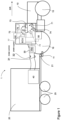
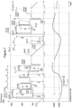
- FIG. 1 shows a vehicle combination 1 comprising a tractor 10 and a trailer 20 which is attached to the tractor hitch system 11 of the tractor 10 via a trailer drawbar 21.
- the tractor 10 comprises front and rear wheels 5, 6 which are braked by a service brake system and a park brake systems which is not described hereinafter in detail as well known in the art.
- a trailer brake system 30 mainly including a trailer brake valve 30a and or further valve arrangements and is provided to forward a pneumatic or hydraulic brake signal to the trailer via the standardized trailer control coupling 31.
- the further trailer supply coupling 32 is provided for air or oil supply to the trailer brakes. Both couplings 31, 32 are used to connected at least the trailer brake system 30 to a brake system 40 of the trailer.
- the brake system 40 serves to actuate the brakes of the wheels 25 of the trailer 20.
- the trailer brake actuation pressure can be generated by trailer brake system 30 e.g. when the driver activates the service brake system with the brake pedal (not shown) and/ or the park brake system (with the handbrake lever) of the tractor 10 so that brake demand is directly forwarded by pressurized fluids such as air or oil to the trailer brake system 30.
- a trailer brake actuation pressure may be generated independent of the direct driver activation but in response to a trailer brake signal TBS coming from an electronic vehicle control unit ECU, which is also referred to as electronic trailer braking. This type of brake signal generation is focused in the following invention.
- the electronic vehicle control unit ECU receives parameter and/or sends control signals to various components of the tractor 10, such as:
- the electronic vehicle control unit ECU has the major task to provide a processing method which includes:
- the trailer brake signal TBS is represented by a pressure demand to control a pneumatic trailer brake system 30.
- the trailer brake signal TBS may be provided to control a hydraulic brake system and the trailer brake valve 30a is also hydraulically operated.
- the trailer brake signal TBS may be forwarded to the trailer brake system by any other means such as an electronic signal if brake-by-wire systems are installed on the trailer.
- the method can be implemented on the electronic vehicle control unit ECU or may alternatively be part of the trailer brake control system 30 when equipped with a respective control unit and interface to receive the above mentioned parameters.
- the electronic vehicle control unit ECU iteratively generates a trailer brake signal TBS to be forwarded to the trailer valve 30a.
- the trailer brake signal TBS receives different values which are described hereinafter.
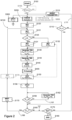
- the electronic vehicle control unit ECU executes the method M100 as depicted in Figure 1 .
- the main method M100 is depicted in several sub processes wherein Figure 2 shows the main method M100 which includes sub process S200 as shown in Figure 3 , sub process S300 as shown in Figure 4 and sub process S400 as shown in Figure 5 .
- the electronic vehicle control unit ECU is initializing the method with step S100.
- the initialization may be triggered if the ignition is ON and the electronic vehicle control unit ECU is energized.
- the initialization may be triggered if the electronic vehicle control unit ECU detect that a trailer 20 is attached to the vehicle 10. This may be determined if the standardized current supply connector (which supplies current to the trailer 20 and/or activates lights or the turn indicator of the trailer 20) is connected to the receiving connector on vehicle 10.
- pre-condition means that these conditions must be met to generally enable activation of the electronic trailer braking while activation parameters serve to determine what event causes deceleration and additionally may establish the degree of deceleration and to adapt the trailer brake signal accordingly.
- step S205 (re)sets status parameters SP DL , SP AS , SP CA , SP CC , SP REV , SP ENG , to zero.
- the status parameter are explained lateron.
- the activation checks pre-conditions which allow the electronic trailer brake function is to be activated and whether and how the vehicle is decelerated, especially but not exclusively if this is done by using the acceleration foot paddle 71or the drive lever 72. Furthermore, this step serves to determine the driver's demand regarding the degree of deceleration, also referred to as the driver deceleration demand DD.
- Step S206a checks a first pre-condition by determining if the coupling force F C,real (see subroutine S300) is below a set value of F CA,min , say -3500 N (in a range of negative sign) to ensure that the trailer 20 significantly pushes the tractor 10 (push condition). There are conditions, in which higher coupling force F c,real (smaller when seen with negative sign) may occur but electronic trailer brake should not be activated. E.g. this condition may occur if an implement is initially coupled to the tractor or if potholes are passed. If NO, the process returns prior to step S206a with loop L207.
- Step S206a must be seen as a pre-condition which , when once met, enables the coupling force F C,real to take any value in the further processing, even being above F CA,min without aborting the process or the activation.
- Step S210a checks if the driveline clutch is activated. This provision is necessary when e.g. the operator intends to let the vehicle combination roll towards a crossing. The method should not be executed further as this results in that the CVT is drivingly disconnected from the wheels so that the determination of the coupling force based on CVT parameters is not possible. So if YES step S210b is proceeded to check next pre-condition while NO would be followed by step S220 explained lateron.
- step S210a is provided subsequent to step S206a (which requires the detection of a coupling force when clutch is disengaged) to make sure that the activation is aborted whenever clutch is subsequently disengaged.
- steps S210b and S210c proceed to check two pre-conditions in an OR relationship which means that one of both is met.
- the vehicle speed shall be v v > 0 kph (or alternatively v SET > 0 kph) or according step S210c the tractor 10 drives uphill with ⁇ ⁇ CA,max , of say -4° as a negative sign is downhill inclination, as both conditions are known for resulting in push condition.
- step S210b may consider a minimum value for the vehicle speed v v or vehicle speed set point v SET to be exceeded to avoid electronic trailer activation at low speeds where push condition is less critical. When one of these pre-condition is met, the method proceeds to step S220 explained lateron. Otherwise, next pre-condition is checked in step S210d.
- the electronic vehicle control unit ECU provides control of the transmission to maintain the output speed of the transmission (and thereby the wheels) at zero rpm to compensate unmeant movement resulting from idle oil flow in the hydraulic branch of the CVT (as described in applicant's published patent applications EP 1 990 230 and EP 2 935 948 ).
- the hydraulic units are permanently adjust which may result in that a coupling force may be detected which should not result in trailer brake activation.
- the steps S210b, S210c and S210d serve to enable electronic trailer braking when driving on even ground, uphill or downhill and when the tractor stands still on downhill as push condition may be present. But when standing uphill or on even ground, activation shall be prohibited as these conditions will not result in push condition.
- step S210d results in YES
- the loop L210 returns prior to step 210 with status parameters SP CA remaining zero.
- step S210d may result in further processing of step S220 or a loop which returns prior to step 210 with status parameters SP CA remaining zero.
- the method detects in which way the operator inputs a demand to decelerate the vehicle (without actuating service or park brake). This is done in activation branches B211, B212, B213, B214 and B215.
- Activation branch B211 commences with step S220, in which the activation via the drive lever 72 is checked. If the operator intends to decelerate the vehicle, he pushes back the drive lever 72 in the opposite direction as indicated with arrow DR. Thereby, the demand value V DL which is forwarded to the ECU is in a minus range and the parameter V DLminus is set to 1. If the drive lever 72 is released, vehicle speed remains constant so that parameter V DLminus is set to 0.
- step S225 in which the status parameter SP DL is set to 1 indicating that the deceleration is inputed via drive lever 72.
- step S226 in which the value of the acceleration rate input 73 is determined.
- the acceleration rate input 73 serves to determine the operators input regarding the driver deceleration demand DD on response of the operator's input and therefore offers four set points: level I, II, III, IV. If the operator adjusts the acceleration rate input 73 to level I in which the status parameter SP AS would receive the value 1, the driving speed of the vehicle decreases at slowest so that the deceleration is low and smooth. At Level IV in which the status parameter SP AS would receive the value 4 the driving speed of the vehicle speed decreases rapidly and would result in an "aggressive" deceleration.
- the drive lever may provide a proportional speed control which means that the acceleration rate depends on the deflection angle or the deflection speed.
- an acceleration grade input 73 may not be present but the status parameter SP AS would be set depending on deflection angle or speed.
- activation branch B212 is further executed in which further operator inputs are checked.
- branch B212 branches of in branch B213, B214 and B215.
- step S230 the process checks deactivation of the cruise control in step S230. If YES, the deceleration via the speed foot paddle 71 is checked with step S232.
- the speed foot paddle 71 is depressed by the operator's foot and forwards the speed demand to the ECU. This is different to the driver lever 72 in that the deflection angle is proportional to the demand value for the vehicle speed. In other words, if fully depressed, the demand is maximum vehicle speed or alternatively any vehicle speed limit value which the driver can set via the HMI terminal 75. E.g. if the vehicle is operated for shunting, the driver may set a lower speed assigned to full pedal depression to increase the pedal resolution and enable finer control.
- step S232 checks if the pedal mode is activated. If not, depressing the speed foot paddle 71 would not impact the vehicle movement but only adjust engine speed. As a consequence, the loop L233 returns prior to step S205.
- Step S234 checks if the speed foot paddle 71 is completely released (after depression), so that V FP is set to 0. If not, the loop L235 returns prior to step S205.
- step S236 sets the status parameter sp DL to zero.
- status parameter sp DL is generally providing the information if speed foot paddle 71 or drive lever 72 indicate deceleration.
- step S230 indicates activation of the cruise control, branches B213 is proceeded to determine subsequent condition present in cruise control mode.
- step S240 determines if the current vehicle speeds exceeds the set point of the cruise control.
- cruise control mode may still result in a situation where electronic trailer braking is demanded, referred to as the second cruise control mode. This may happen if the vehicle combination drives in cruise control mode on an even course and then enters a downhill passage. The weight of the trailer would then start to push the tractor resulting in an increase of the vehicle speed and a deviation from the set point.
- step S240 determines conditions in cruise control mode in which the vehicle speed is considerably changed with v v > f CAv * v SET which is when the current vehicle speed v v exceeds the speed set point v SET of the cruise control about a factor f CAv .
- loop L241 returns prior to step S205.
- step S242 sets the status parameter for activation in cruise control mode SP CC to 1 indicating the activation of electronic trailer braking based on a condition in cruise control mode.
- the status parameter SP AS is stored in step S243 similar to step S226.
- status parameter SP AS may always set to one single value, say 2, when the set point is not changed but the vehicle speed increases relative to set point on downhill drive in second cruise control mode.
- a further condition is checked with branch B214 in which the process determines reversing of the tractor.
- Reversing of the tractor or the vehicle combination means that the operation of the tractor is changed from a first, say forward direction at a predetermined vehicle speed to the opposite direction with the same or a preselected vehicle speed. So reversing always results in deceleration which may cause push condition so that electronic trailer brake must be activated. Reversing can be activated by an operator user interface. The tractor is than decelerated, passes standstill and is changed to the opposite direction driving without further manual intervention. This function offers a comfortable manoeuvring, e.g. during front loader operation. Reversing of the tractor 10 can be initiated by various inputs:
- the driver can chose if reversing is provided only by changing the direction, but with the same speed, or changing direction and decelerate/accelerate to a set point which can be pre-selected in the HMI terminal 75 for each driving direction. This is advantageous drivers may prefer to drive slower in rearward driving
- step S250 the method checks if the tractor is reversed. If NO the loop L251 returns prior to step 205.
- the status parameter SP REV is set to 1 in step S252 and as the degree of deceleration depends on the setting of the acceleration rate input 73, the status parameter SP AS is stored in step S253.
- step S260 monitors a decrease of the engine speed.
- the HMI terminal enable driver to save to set points MAX and MIN for different engine speed set points. Both values can be selected by pushing a button assigned to MAX and MIN which may be positioned close or on the drive lever 72.
- tractor 10 may be equipped with a hand throttle (not shown) which enables the driver to directly adjust engine speed via a rotary control.
- This branch may additionally include the determination of a further status parameter to consider a degree of deceleration depending of the absolute value of the difference in engine speed ⁇ n ENG .
- step S270 All activation branches B211,B212, B213, B214, B215 merge to step S270 in which, when one of the activation requirements in branches B211 to B215 is met, the status parameter SP AS is set to 1, indicating that the activation is generally enabled, independent of whether by drive lever 72 or speed foot paddle 71 or any other condition caused the activation ..
- step S250 the method proceeds to step 120 as depicted in Figure 2 .
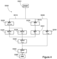
- step S300 determines the actual coupling force F c,actual by considering various driving dynamic parameters as depicted in Figure 4 .
- the mass m v of the vehicle is determined according the prior art and is not described in detail.
- the mass m v may be determined by considering the empty weight of the tractor plus additional ballast attached thereto. These values may be stored in the ECU. Alternatively, mass values could be taken from vehicle acceleration or wheel load detection. A method is described in applicant's published patent application EP2766239 .
- both values may be determined by gyroscope 60 which may be part of a GPS navigation system.
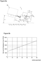
- the force must be inserted with negative or positive signs according the effective direction shown in Figure 6a .
- F TRV F IN + F H + F AR + F R , RA + F R , FA
- the Overall Resistance Force F R is taken from the graph shown in Figure 6b in which the vertical axis shows the Overall Resistance Force F R and the horizontal axis shows the vehicle speed v.
- the graph is determined by coast down tests during development and is then stored for each vehicle series in the ECU.
- the shown graph is determined for a vehicle on asphalt (or road operation).
- further graphs may be determined for grassland, farmland or gravel tracks which could then be considered when the vehicle is provided with means to detect on which terrain the vehicle drives. This may be determined by GPS navigation system which delivers the geographic information, eg. if the vehicles is driving on a public road (on asphalt), on a gravel track or offside any road, which may be grassland or farmland.
- the Tractive Force of the vehicle combination FTRC is determined as known in prior art by measuring the fluid pressure in a Continuously Variable Transmission (CVT) of the hydrostatic-mechanical split type which includes a hydraulic drive circuit in which a hydraulic pump supplies pressurized fluid to a hydraulic motor. Details are explained in applicant's published patent application WO2013/053645 and are no explained in detail. Alternatively, any other means to determine the Tractive Force of the vehicle combination FTRC such as using the torque supplied by the engine to receive the tractive force as described in US 4 548 079 may be taken instead. (See GB11/44)
- the Coupling force can then be received with equation E7.
- a first branch B305 determines the Tractive Force of the vehicle combination F TRC in step S335 as explained above.
- a second branch B310 determines the mass m v , acceleration a and the inclination ⁇ in step S320 as explained above to further calculate Inertia Force F IN in step S325 and downhill-slope Force F H in step 326.
- step S330 determines speed v of as explained above to further determine Overall Resistance Force F R in step S331 with reference to Figure 6b .
- Second branch B310 and third branch B315 then proceeds into step S340 to calculate Tractive Force of the towing vehicle F TRV as defined with equation E6.
- step S335 and S340 are then used to calculate the actual Coupling Force F C . actual according equation E7.
- sub process S300 is permanently proceeded to deliver the actual Coupling Force F C,actual for further steps.
- the method M100 in Figure 2 further continues with permanently monitoring the status parameter SP CA in step S110 which indicates that the driver still demands vehicle deceleration via speed foot paddle 71 or drive lever 72. If the activation is interrupted and status parameter SP CA is changed to zero, the loop L211 resets all parameters in step S115 and returns to START.
- step S120 is setting a first interval counter c, also referred to as the brake interval counter) to zero.
- a first timer value t 0 is also set to zero (seconds) and a timer is started.
- EU-Regulation 2015/68 dated 15.10.2014
- Appendix I Number 2.2.1.19.1
- EU Mother regulation RVBR also referred to as "EU Mother regulation RVBR" which limits the duration of electronically activated trailer braking (without the driver operating the service brake) to a maximum duration of 5 s. After this the trailer brake must be released.
- the first time value t 0 is used to monitor the time limit while the brake interval counter c is used to determine the number of the brake intervals.
- a brake interval is thereby characterised by a time period in which the electronic trailer brake control is activated/enabled and may be followed by an optional pause time, in which the trailer brake is not activated. The next brake interval starts when the trailer brake is activated again after being in pause.
- the brake interval is thereby interrupted if activation requirements as described in step 200 are not meet and status parameter SP CA returns to zero. This results in the reset of all parameters in step 115 and thereby also the first interval counter c and first timer value t 0 , discussed in detail herein.
- Step S125 checks if the method is currently proceeding in the first brake interval (meaning that the time limit has not been exceeded) or in a subsequent brake interval.
- the pressure level depends on setting of the acceleration rate input 73 which is provided by status parameter SP AS :
- step S260 If the deceleration results from the engine speed decrease with step S260 resulting in YES (and the status parameter SP ENG set to 1), the pilot pressure P P,0 is set to 80 kPA
- the set values for pilot pressure P P,0 depending on status parameter SP AS are shared over different deceleration conditions (with one of status parameters SP DL , SP CA , SP CC , SP REV , SP ENG set to 1) but may alternatively be defined differently for each deceleration conditions.
- a trailer brake signal TBS is generated, also referred to "First-in-Shot" .
- This step serves to provide a pressure peak which is used to fill the lines on the trailer.
- This step is provided to keep bias the system and make it more responsive.
- the height of the Trailer brake signal TBS, or the trailer brake actuation pressure must be chosen high enough to fill the lines but low enough to avoid an excessive brake reaction which would result in jerking and negative impact on driving comfort. Therefore the "First-in-Shot" is time controlled and depends on the driver deceleration demand DD as determined in step S200.
- the first-in-shot-pressure P FIS is to 300 kPA and the duration is set to 0,03 s
- the pressure level and duration depends on setting of the acceleration rate input 73 which is provided by status parameter SP AS :
- step S260 If the deceleration results from the engine speed decrease with step S260 resulting in YES (and the status parameter SP ENG set to 1), the pilot pressure P P,0 is set to 80 kPA
- the set values for first-in-shot-pressure P FIS is to 300 kPA and the duration depending on status parameter SP AS are shared over different deceleration conditions (with one of status parameters SP DL , SP CA , SP CC , SP REV , SP ENG set to 1) but may alternatively be defined differently for each deceleration conditions.
- the Correction factor f 1 is in a range between >0 ..1 and considers the fact that with increasing vehicle speed, high First-in-Shot pressure peaks result in that the trailer tends to jerk which negatively impacts the driving comfort. On the other hand, when the vehicle combination 1 drives downhill, the trailer brake system reaction should be as fast as possible.
- the Correction factor f 2 is also in a range between >0 ..1 and considers the fact pressure level of the "First-in-Shot" is reduced during the process to avoid overshoots in the trailer brake actuation pressure reducing driving comfort.
- the equation for correction factor f 2 is:
- step S140 is straight away generating a trailer brake signal TBS based on the pressure determination as described in Steps 131, 132.
- the trailer brake signal TBS generated in step S135 is maintained constant until the ECU is generating a further pressure signal TBS as explained herein.
- step S145 the process is waiting for 0,75 s to enable the ECU to determine the actual coupling force F C, actual as described with step S300.
- the waiting period is necessary to consider the effects of the trailer brake signals TBS generated with steps S135, S140 and the resulting changes in the actual coupling force F C, actual . Otherwise, the ongoing process would be based on a coupling force F C,actual which is still changes under the influence of steps S135, S140.
- step S140 serve to provide a fast reaction on the deceleration in form of trailer brake signal TBS based on predetermined pressure values while in the ongoing process, a 3-point control algorithm is applied to determine trailer brake signal TBS. This makes the system responsive in the first.
- control algorithm is executed with step S400 as explained in detail in Figure 5 .
- Step S400 and the subsequent steps S401 to S 490 mainly contains the steps to control the trailer brake signal TBS by means of a 3-point controller.
- a 3-point controller represents a discontinuous controller type and takes three values, which are 1, 0 and -1.
- trailer brake signal TBS respective the pressure value is increased, kept constant or decreased.
- continuous controller types such as P, I, or D-Controllers or combinations of them
- the 3-point controller tends less to overshooting and can be handled easier in terms of setting parameters to influence the controller dynamics. Especially these values may be easier adapted to operating conditions, which may be done by the driver or trained service personal.
- step S405 is setting a status parameter, the In-Shot parameter SP IS .
- the in-Shot serves to increase responsiveness by supporting the pressure build up in the trailer brake system 40. But as pressure peaks may result in jerking of the trailer, the In-Shots may be deactivated if the Coupling force (which is permanently determined shows) a rapid decrease. As a rapid decrease (determined in Step S300) indicates a fast reaction to trailer brake signal TBS further In-shots may be omitted. The in-shot is explained in more detail herein.
- step S406 is proceeded in which the ECU takes the predetermined values defining a coupling force range defined by lower coupling force F C,L and a upper coupling force F C , L which is need to realize a 3-point controller and which is explained herein.
- a second interval counter i also referred to as the controller interval counter, is set to zero in step S407.
- the controller pressure p PC,0 is taken from the subsequent controller interval as stored in step S465 and depicted with p PC,i . This results in the advantage that after the controller pressure p PC,0 always receives the value which was last generated in the previous controller interval. This avoids trailer brake signal peaks between brake intervals which would decrease driving comfort.
- step S420 the 3-point controller is adjusting the pressure values based on the initial settings of controller pressure p Pc,0 in step S415, S416.
- step S406 the coupling force band defined by lower coupling force F C,L and upper coupling force F C,L is now explained in detail. Both values have a negative sign (as they are counteracting the vehicle) and are needed to operate the 3-point controller.
- the lower coupling force F C,L represents a value which shall not be undercut as this may cause the vehicle 10 to become unstable due to the force applied and the resulting yaw moment about the vertical vehicle axis.
- This value is stored in the ECU and may vary for different vehicle configurations. E.g. a lightweight vehicle cannot bear the same force/yaw moment compared a vehicle 10 with higher weight. The same applies depending on wheel base or wheel width which also influence the vehicle stability.
- the upper coupling force F C,L represents a value which shall not be exceed as the brake actuation shall be stopped before the coupling force gets zero.
- the 3-point controller checks the value of the actual coupling force F C, actual relative to the coupling force band defined by lower coupling force F C,L and upper coupling force F C,L .
- the value for AP PC,set is stored in the ECU and is 15 kPA. This means, that the pressure will be increased to increase brake force on the trailer.
- the method then proceeds in two parallel branches into the steps encircled with a dotted line 440 which serve to apply the In-shot not.
- step S441 results in that step S445 is proceeded. Otherwise the method proceeds to Step 451 without applying in-shot.
- the value ⁇ P IC,set and the time t IS1 is stored in the CU and is 100 kpa and 0,05s.
- step S442 results in that step S446 is proceeded. Otherwise the method proceeds to Step 451 without applying in-shot.
- the value ⁇ P IC,set and the time t IS2 is stored in the CU and is 100 kpa and 0,1 s.
- the duration in this step is greater as with step S445 due to the fact that the reaction time of the trailer brake system is higher when the pressure is decreased. This is balanced by a longer in-Shot duration.
- step S450 in which pressure values are set:
- This step overwrites the trailer brake signal TBS generated in step S140 (in Figure 2 ).
- the last value of the trailer brake signal TBS is then saved in the ECU with step S465 for consideration in the next controller interval in step S416.
- step S430 may result in that the method is proceeds with step S465 as there is no pressure increase and the trailer brake pressure generated in step S140 (see Figure 2 ) is still upheld.
- step S475 the controller interval counter i is increased by 1 for characterising an subsequent interval as requested for step S410.
- step S145 the process is waiting for 0,75 s to enable the ECU to determine the actual coupling force F C, actual as described with step S300 and then return prior to step 410.
- step S490 aborts the sub process S400 and returns to main method M100 depicted in Figure 2 .
- sub process S400 is continuously adapting the trailer brake signal TBS by applying the 3-point controller and an optional In-shot until the time of 4s is reached. In the meantime, the process passes several controller interval, whereby subsequent interval are based on the trailer brake signal TBS generated in the previous interval.
- step S150 saves the last value of the trailer brake signal in the ECU for consideration in the next brake interval in step S132.
- step S475 the brake interval counter c is increased by 1 for characterising an subsequent interval as requested for step S125.
- the timer value T 0 is provided to ensure that the brake actuation is not active for more than 5 s.
- the sub process S400 is aborted after 4 s. The remaining time of 1 s is used to ramp down the trailer brake signal TBS to zero before the 5s are passed.
- Equation E10 For a last trailer brake signal TBS of 100 kPa equation E10 would determine a ramp pressure decrease ⁇ p R of 4kPa.
- step S160 does not show that the trailer brake signal TBS is zero
- the loop L161 and step S162 is repeatedly proceeded to generate a trailer brake signal TBS which is reduced with ⁇ p R .
- the loop L161 is repeated and returns prior to step S160 until the trailer brake signal TBS is zero.
- step S175 checks if a shut-down condition is met so that the method is ended with step S180. We have chosen Ignition OFF in step S175.
- FIG. 7 briefly depicts the results of the method according the invention.
- the horizontal axis depicts the time in which the method proceeds.
- the vertical axis is shows two portions:
- step S131 determines the Pressure value P FIS of the First-In-Shot which is then generated at step S135. During the waiting period in step S145, the Pilot pressure P FIS kept. Then the process proceeds to step S400.
- the In-Shot with p IS is applied with step S455 based on the determination in steps S438, S445, S450.
- step S460 the controller pressure P PC is generated based on the determination in step S438.
- the steps S438, S445, S450 deliver an positive pressure increase as the coupling force F C,actual is below F C,L . This is repeated until the coupling force F C,actual is above the F C,L .
- a negative pressure increase is determined in steps S439, S446, S450 for generating the in-shot p IS in S455 and the controller pressure P PC in step 460.
- step S480 timer t 0 reaches 4s and the 3-pont-controller is aborted.
- step S480 timer t 0 reaches 4s and the 3-pont-controller is aborted.
- step S480 the trailer brake signal TBS and pressure p TBS is ramped down in steps L161/s162. After 5s (overall, or 1s of down ramping) the pressure p TBS is to zero. A waiting period of 1s is then applied with step S170.
Landscapes
- Engineering & Computer Science (AREA)
- Mechanical Engineering (AREA)
- Transportation (AREA)
- Human Computer Interaction (AREA)
- Physics & Mathematics (AREA)
- Fluid Mechanics (AREA)
- Regulating Braking Force (AREA)
Claims (12)
- Steuersystem zum Steuern des Betriebs eines Anhängerbremssystems (30), welches einer landwirtschaftlichen Fahrzeug-Anhänger-Kombination (1) zugeordnet ist, wobei das Steuersystem eine Fahrzeugsteuereinheit (ECU) aufweist und konfiguriert ist, umeine Kupplungskraft zwischen dem Fahrzeug (10) und dem Anhänger (20) zu ermitteln, undSteuersignale zu generieren und auszugeben zum Steuern des Betriebs des Anhängerbremssystems (30) in Abhängigkeit von der ermittelten Kupplungskraft;wobei das Steuersystem konfiguriert ist, umdadurch gekennzeichnet dass, das Steuersystem konfiguriert ist, umden Betrieb des Anhängerbremssystems (30) entsprechend einer primären Steuerstrategie in Abhängigkeit davon, dass die ermittelte Kupplungskraft innerhalb eines Kupplungskraft-Bereiches ist, zu steuern;den Betrieb des Anhängerbremssystems (30) entsprechend einer oder einer von mehreren sekundären Steuerstrategien in Abhängigkeit davon, dass die ermittelte Kupplungskraft außerhalb des Kupplungskraft-Bereichs ist, zu steuern;die ermittelte Kupplungskraft mit einem oberen Kupplungskraft-Grenzwert und einem unteren Kupplungskraft-Grenzwert zu vergleichen, um zu ermitteln, ob die Kupplungskraft innerhalb des Kupplungskraft-Bereichs liegt; undden Betrieb des Anhängerbremssystems (30) entsprechend einer zweiten sekundären Steuerstrategie zu steuern in Abhängigkeit davon, dass die ermittelte Kupplungskraft den oberen Kupplungskraft-Grenzwert überschreitet, wobei die zweite sekundäre Steuerstrategie eine Verringerung eines Druckniveaus des Anhängerbremssystems (30) beinhaltet zur Reduzierung einer Bremskraft, die auf den Anhänger (20) appliziert wird.
- Steuersystems nach Anspruch 1, wobei der untere Kupplungskraft-Grenzwert einer Kupplungskraft entspricht mit oder nahe einem Niveau, durch das die applizierte Kraft und/oder das Giermoment, welches hieraus resultiert, ein für die Fahrzeug-Anhänger-Kombination (1) akzeptables Niveau überschreitet.
- Steuersystem nach Anspruch 2, wobei das akzeptable Niveau der applizierten Kraft und/oder des applizierten Giermoments von der Masse des Fahrzeugs (10) und/oder dem Rad- oder Achsstand des Fahrzeugs oder des Anhängers (20) und/oder Radbreite des Fahrzeugs (10) oder Anhängers (20) abhängig ist.
- Steuersystem nach Anspruch 1 oder einem davon abhängigen Anspruch, wobei die obere Kupplungskraft auf ein Niveau zur Gewährleistung, dass die Betätigung des Anhängerbremssystems (30) verhindert ist, bevor die Kupplungskraft auf Null abfällt, gesetzt wird.
- Steuersystem nach Anspruch 1 oder einem davon abhängigen Anspruch, welches konfiguriert ist, um den Betrieb des Anhängerbremssystems (30) entsprechend einer ersten sekundären Steuerstrategie in Abhängigkeit davon, dass die ermittelte Kupplungskraft unter dem unteren Kupplungskraftgrenzwert liegt, zu steuern; wobei die erste sekundäre Steuerstrategie eine Erhöhung eines Druckniveaus des Anhängerbremssystems (30) beinhaltet zur Erhöhung einer Bremskraft, die auf den Anhänger (20) aufgebracht wird.
- Steuersystem nach einem der vorhergehenden Ansprüche, welches konfiguriert ist zur Ermöglichung der Kupplungskraft in Abhängigkeit mindestens einer der folgenden Größen:eine Zugkraft, die von dem Motor und dem Getriebe (50) des Fahrzeugs (10) bereitgestellt wird und auf die Räder des Fahrzeugs (10) aufgebracht wird;eine Trägheitskraft infolge einer Beschleunigung oder Abbremsung der Fahrzeug-Anhänger-Kombination (1);eine Neigungskraft infolge der Neigung der Fahrzeug-Anhänger-Kombination (1);der Masse des Fahrzeugs (10) und/oder des Anhängers (20);ein Luftwiderstand; undein Rollwiderstand.
- Steuersystem nach einem der vorhergehenden Ansprüche, wobei das Anhängerbremssystem (30) ein hydraulisches Bremssystem aufweist und das Steuersystem konfiguriert ist, um einen Öldruck für mindestens eine Fluidleitung des hydraulischen Bremssystems zu steuern.
- Steuersystem nach einem der Ansprüche 1 bis 6, wobei das Anhängerbremssystem (30) ein pneumatisches Bremssystem aufweist und das Steuersystem konfiguriert ist, um einen Luft- oder Gasdruck für mindestens eine Luft- oder Gasleitung des pneumatischen Bremssystems zu steuern.
- Steuersystem nach einem der vorhergehenden Ansprüche, welches geeignet konfiguriert ist, um in Abhängigkeit eines Merkmals eines Betriebsparameters eines Getriebes (50) der Fahrzeug-Anhänger-Kombination (1) eine Kupplungskraft zu ermitteln, die der Kupplung zwischen dem Fahrzeug (10) und dem Anhänger (20) zugeordnet ist.
- Bremssystem mit einem und/oder steuerbar durch ein Steuersystem nach einem der vorhergehenden Ansprüche.
- Landwirtschaftliches Fahrzeug (10), welches mit einem Anhänger (20) zur Bildung einer Fahrzeug-Anhänger-Kombination (1) koppelbar ist und das Steuersystem nach einem der Ansprüche 1 bis 9 aufweist und/oder durch dieses steuerbar ist.
- Verfahren zum Steuern des Betriebs eines Anhängerbremssystems (30), welches einer landwirtschaftlichen Fahrzeug-Anhänger-Kombination (1) zugeordnet ist, miteinem Ermitteln einer Kupplungskraft zwischen dem Fahrzeug (10) und dem Anhänger (20); undeinem Erzeugen und Ausgeben von Steuersignalen zum Steuern des Betriebs des Anhängerbremssystems (30) in Abhängigkeit von der ermittelten Kupplungskraft;wobei das Verfahren aufweist:ein Steuern des Betriebs des Anhängerbremssystems (30) entsprechend einer primären Steuerstrategie in Abhängigkeit davon, dass die ermittelte Kupplungskraft innerhalb eines Kupplungskraft-Bereichs ist;ein Steuern des Betriebs des Anhängerbremssystems (30) entsprechend einer oder einer von mehreren sekundären Steuerstrategie(n) in Abhängigkeit davon, dass die ermittelte Kupplungskraft außerhalb des Kupplungskraft-Bereichs liegt,gekennzeichnet durchein Vergleichen der ermittelten Kupplungskraft mit einem oberen Kupplungskraft-Grenzwert und einem unteren Kupplungskraft-Grenzwert zur Ermittlung, ob die Kupplungskraft in dem Kupplungskraft-Bereich liegt; undein Steuern des Betriebs des Anhängerbremssystems (30) entsprechend einer zweiten sekundären Steuerstrategie in Abhängigkeit davon, dass die ermittelte Kupplungskraft den oberen Kupplungskraft-Grenzwert überschreitet, wobei die zweite sekundäre Steuerstrategie eine Verringerung eines Druckniveaus des Anhängerbremssystems (30) aufweist zur Reduzierung einer Bremskraft, die auf den Anhänger (20) aufgebracht wird.
Applications Claiming Priority (3)
| Application Number | Priority Date | Filing Date | Title |
|---|---|---|---|
| GBGB2100651.5A GB202100651D0 (en) | 2021-01-19 | 2021-01-19 | Trailer brake control system |
| GB202111426 | 2021-08-09 | ||
| PCT/IB2021/061303 WO2022157574A1 (en) | 2021-01-19 | 2021-12-03 | Trailer brake control system |
Publications (2)
| Publication Number | Publication Date |
|---|---|
| EP4281340A1 EP4281340A1 (de) | 2023-11-29 |
| EP4281340B1 true EP4281340B1 (de) | 2025-05-21 |
Family
ID=78916691
Family Applications (7)
| Application Number | Title | Priority Date | Filing Date |
|---|---|---|---|
| EP21824673.4A Active EP4281339B1 (de) | 2021-01-19 | 2021-12-03 | Anhängersteuergerät |
| EP21824676.7A Active EP4281341B1 (de) | 2021-01-19 | 2021-12-03 | Anhängersteuergerät |
| EP21824679.1A Active EP4281344B1 (de) | 2021-01-19 | 2021-12-03 | Anhängersteuergerät |
| EP21824672.6A Active EP4281338B1 (de) | 2021-01-19 | 2021-12-03 | Anhängerbremssteuerungssystem |
| EP21824677.5A Active EP4281342B1 (de) | 2021-01-19 | 2021-12-03 | Anhängersteuergerät |
| EP21824675.9A Active EP4281340B1 (de) | 2021-01-19 | 2021-12-03 | Anhängersteuergerät |
| EP21824678.3A Active EP4281343B1 (de) | 2021-01-19 | 2021-12-03 | Anhängersteuergerät |
Family Applications Before (5)
| Application Number | Title | Priority Date | Filing Date |
|---|---|---|---|
| EP21824673.4A Active EP4281339B1 (de) | 2021-01-19 | 2021-12-03 | Anhängersteuergerät |
| EP21824676.7A Active EP4281341B1 (de) | 2021-01-19 | 2021-12-03 | Anhängersteuergerät |
| EP21824679.1A Active EP4281344B1 (de) | 2021-01-19 | 2021-12-03 | Anhängersteuergerät |
| EP21824672.6A Active EP4281338B1 (de) | 2021-01-19 | 2021-12-03 | Anhängerbremssteuerungssystem |
| EP21824677.5A Active EP4281342B1 (de) | 2021-01-19 | 2021-12-03 | Anhängersteuergerät |
Family Applications After (1)
| Application Number | Title | Priority Date | Filing Date |
|---|---|---|---|
| EP21824678.3A Active EP4281343B1 (de) | 2021-01-19 | 2021-12-03 | Anhängersteuergerät |
Country Status (3)
| Country | Link |
|---|---|
| US (7) | US12454255B2 (de) |
| EP (7) | EP4281339B1 (de) |
| WO (8) | WO2022157578A1 (de) |
Families Citing this family (10)
| Publication number | Priority date | Publication date | Assignee | Title |
|---|---|---|---|---|
| WO2022157578A1 (en) * | 2021-01-19 | 2022-07-28 | Agco International Gmbh | Trailer brake control system |
| GB2620183B (en) * | 2022-06-30 | 2024-10-09 | Bamford Excavators Ltd | A method and system for enhanced braking in a tractor unit |
| US12263823B2 (en) * | 2022-12-19 | 2025-04-01 | Bendix Commercial Vehicle System Llc | Braking control apparatus and method determining trailer brake pressure model based on trailer information |
| US12304444B2 (en) * | 2023-02-09 | 2025-05-20 | GM Global Technology Operations LLC | Methods and systems for automatic trailer brake gain scaling |
| US12304445B2 (en) | 2023-02-09 | 2025-05-20 | GM Global Technology Operations LLC | Automatic trailer brake gain scaling system and method using hitch forces |
| US12269472B2 (en) | 2023-03-21 | 2025-04-08 | GM Global Technology Operations LLC | Systems and methods for determining vehicle and trailer resistance related characteristics |
| US20250010824A1 (en) * | 2023-07-03 | 2025-01-09 | Lippert Components, Inc. | Trailer panic braking assist |
| DE102023207020A1 (de) * | 2023-07-24 | 2025-01-30 | Zf Friedrichshafen Ag | Verfahren zum Ermitteln eines Zustands einer Bremseinrichtung eines Anhängers |
| GB202313366D0 (en) * | 2023-09-01 | 2023-10-18 | Agco Int Gmbh | Trailer brake temperature estimation |
| GB202405473D0 (en) | 2024-04-18 | 2024-06-05 | Agco Int Gmbh | Manual brake controlling of a trailer brake |
Citations (5)
| Publication number | Priority date | Publication date | Assignee | Title |
|---|---|---|---|---|
| US5522649A (en) | 1992-05-09 | 1996-06-04 | Wabco Standard Gmbh | Process and apparatus for monitoring a trialer brake for overload |
| US20040051374A1 (en) | 2002-09-18 | 2004-03-18 | Zbinden Posieux Sa | Method of controlling the braking device of a trailer and braking device operating according to this method |
| DE102009031851A1 (de) | 2009-07-03 | 2011-01-05 | Dipl. Ing. Tietjen Gmbh | Abbremsung einer Zugfahrzeug-Anhänger-Kombination |
| EP3569458A1 (de) | 2018-05-15 | 2019-11-20 | CLAAS Tractor S.A.S. | Verfahren zum betreiben eines bremssystems eines landwirtschaftlichen zuges, bremssystem für einen landwirtschaftlichen zug sowie landwirtschaftlicher zug |
| US20200040956A1 (en) | 2018-08-01 | 2020-02-06 | Bendix Commercial Vehicle Systems Llc | Method for using brake pad information in braking applications |
Family Cites Families (62)
| Publication number | Priority date | Publication date | Assignee | Title |
|---|---|---|---|---|
| DE3246201A1 (de) | 1982-12-14 | 1984-06-14 | Wabco Westinghouse Fahrzeugbremsen GmbH, 3000 Hannover | Verfahren und einrichtung zur ermittlung des gewichtes eines fahrzeuges |
| US4771838A (en) * | 1987-05-21 | 1988-09-20 | Ketcham George M | Obedient self-powered slave vehicles |
| US5149121A (en) | 1987-08-05 | 1992-09-22 | Pfister Gbmh | Force measuring device |
| GB8827101D0 (en) | 1988-11-19 | 1988-12-21 | Lucas Ind Plc | Trailer brake control for towing vehicles having electronic brake control |
| US5005130A (en) * | 1989-12-20 | 1991-04-02 | Eaton Corporation | Trailer swing control |
| US5330020A (en) * | 1991-06-03 | 1994-07-19 | Ketcham George M | Self-powered towing servomechanism |
| DE4438222B4 (de) | 1994-10-26 | 2008-02-14 | Knorr-Bremse Systeme für Nutzfahrzeuge GmbH | Verfahren und Vorrichtung zur Steuerung bzw. Regelung der Bremsanlage eines Fahrzeugs |
| DE19521872B4 (de) * | 1995-06-16 | 2006-03-16 | Knorr-Bremse Systeme für Nutzfahrzeuge GmbH | Verfahren zur Steuerung der Bremsanlage eines Fahrzeugs |
| JP3715321B2 (ja) | 1995-07-14 | 2005-11-09 | クノーループレムゼ ジュステーメ フュア ヌッツファールツォイゲ ゲーエムベーハー | 複合車両用の制動(ブレーキ)制御装置 |
| GB9524048D0 (en) * | 1995-11-24 | 1996-01-24 | Lucas Ind Plc | Electronic braking system for road vehicles operating with a trailer |
| SE522239C2 (sv) | 2001-10-03 | 2004-01-27 | Scania Cv Ab | Förfarande och system för bromsaktivering av ett nyttofordon |
| DE10219040A1 (de) | 2002-04-29 | 2003-11-13 | Wabco Gmbh & Co Ohg | Verfahren und Anordnung zur Zuspannenergieregelung bei elektronisch geregelten Bremssystemen von Fahrzeugkombinationen aus wenigstens einem Zug- und Anhängerfahrzeug |
| DE10219039A1 (de) | 2002-04-29 | 2003-11-13 | Wabco Gmbh & Co Ohg | Verfahren und Anordnung zur Überwachung von Fahrzeugbremsen elektronisch geregelter Bremssysteme von Fahrzeugen und Fahrzeugkombinationen auf Überlast |
| US20060033308A1 (en) * | 2002-11-08 | 2006-02-16 | Continental Teves Ag & Co.Ohg | Method and system for stabilizing a car-trailer combination |
| DE10327564A1 (de) * | 2003-06-18 | 2005-01-05 | Robert Bosch Gmbh | Verfahren zur Bremsregelung eines Kraftfahrzeug-Anhängers |
| SE533870C2 (sv) * | 2005-07-11 | 2011-02-15 | Volvo Lastvagnar Ab | System och förfarande för stabilisering av en fordonskombination |
| WO2008086087A2 (en) * | 2007-01-03 | 2008-07-17 | Ken Degrave | Hybrid trailer system |
| DE102007021732A1 (de) | 2007-05-09 | 2008-11-20 | Agco Gmbh | Antriebssystem für Fahrzeuge mit mindestens zwei antreibbaren Fahrzeugachsen |
| DE102008024630A1 (de) | 2008-05-21 | 2009-11-26 | Wabco Gmbh | Fahrzeugkombination mit einer Streckbremsvorrichtung |
| DE102008048208B4 (de) | 2008-09-20 | 2010-07-01 | Haldex Brake Products Gmbh | Bremseinrichtung für ein hydraulisch gebremstes Zugfahrzeug mit pneumatisch gebremstem Anhänger |
| DE102009004023B4 (de) * | 2009-01-08 | 2018-07-12 | Knorr-Bremse Systeme für Nutzfahrzeuge GmbH | Verfahren zum Steuern eines Start-Stop-Betriebs eines Fahrzeugs mit Hybridantrieb und ein entsprechendes Fahrzeug |
| DE102009045191C5 (de) | 2009-09-30 | 2020-08-13 | Haldex Brake Products Aktiebolag | Verfahren zum Betrieb einer Bremseinrichtung für ein hydraulisch gebremstes Zugfahrzeug |
| DE102009050793A1 (de) | 2009-10-27 | 2011-04-28 | Robert Bosch Gmbh | Adaptives Bremssystem für Lastanhänger |
| DE102010038766A1 (de) | 2010-08-02 | 2012-02-02 | Deere & Company | Zugfahrzeug |
| DE102011053707B4 (de) | 2011-09-16 | 2017-01-26 | Haldex Brake Products Aktiebolag | Druckluftaufbereitungseinheit |
| GB201117720D0 (en) | 2011-10-13 | 2011-11-23 | Agco Int Gmbh | Method to determine vehicle weight |
| GB201117724D0 (en) | 2011-10-13 | 2011-11-23 | Agco Int Gmbh | Hitch control system |
| DE102012101501B4 (de) | 2012-02-24 | 2016-05-04 | Haldex Brake Products Gmbh | Landwirtschaftliches Zugfahrzeug |
| GB2500221A (en) | 2012-03-14 | 2013-09-18 | Tractair Ltd | Vehicle brake apparatus having a trailer with an electro-pneumatic valve, controlled based on a vehicle parameter signal |
| FI125919B (fi) | 2012-08-14 | 2016-04-15 | John Deere Forestry Oy | Työkonejärjestelmä ja menetelmä työkonejärjestelmän ohjauksessa |
| DE102012024982B4 (de) * | 2012-12-20 | 2023-05-25 | Zf Cv Systems Hannover Gmbh | Verfahren zur Zuspannenergieregelung einer Fahrzeugkombination, EBS-Steuereinrichtung und Fahrzeugkombination |
| GB201223546D0 (en) | 2012-12-21 | 2013-02-13 | Agco Int Gmbh | Control mechanism for a continuously variable transmission |
| DE102013103068A1 (de) | 2013-03-26 | 2014-10-02 | Knorr-Bremse Systeme für Nutzfahrzeuge GmbH | Verfahren und Vorrichtung zur Abbremsung eines Anhängers einer Zugfahrzeug-Anhängerkombination |
| DE102014100069A1 (de) | 2014-01-07 | 2015-07-09 | Knorr-Bremse Systeme für Nutzfahrzeuge GmbH | Verfahren zum Steuern einer Bremseinrichtung einer Zugfahrzeug-Anhängerkombination und Bremseinrichtung gesteuert nach dem Verfahren |
| DE102014220686A1 (de) | 2014-10-13 | 2016-04-14 | Deere & Company | Verfahren zur Ansteuerung eines Bremssystems |
| CN108025723B (zh) | 2015-09-23 | 2021-11-23 | 爱科国际有限公司 | 车辆拖车制动系统和方法 |
| DE102015015922A1 (de) * | 2015-12-09 | 2017-06-14 | Wabco Gmbh | Verfahren zum Einstellen von Bremsdrücken an pneumatisch betätigten Radbremsen eines Fahrzeugs, Bremsanlage zur Durchführung des Verfahrens sowie Fahrzeug |
| US9738125B1 (en) * | 2016-05-17 | 2017-08-22 | Horizon Global Americas Inc. | Communication device, system, and method for active control of external vehicle components |
| US10173652B2 (en) | 2016-07-28 | 2019-01-08 | Deere & Company | Hydraulic trailer brake circuit for adjustable gain and improved stability |
| WO2018106900A1 (en) | 2016-12-07 | 2018-06-14 | Horizon Global Americas Inc. | Automated gain and boost for a brake controller |
| US10994715B2 (en) | 2017-01-31 | 2021-05-04 | Hall Labs Llc | Auto gain adjusting trailer brake controller |
| US10479334B2 (en) | 2017-05-24 | 2019-11-19 | Ford Global Technologies, Llc | Method to automatically adjust a trailer brake controller |
| US10960860B2 (en) | 2017-08-07 | 2021-03-30 | Curt Manufacturing, Llc | Brake controller interface |
| DE102017119637A1 (de) | 2017-08-28 | 2019-02-28 | Claas Tractor Sas | Landwirtschaftlicher Zug |
| GB2566492B (en) | 2017-09-15 | 2020-06-17 | Jaguar Land Rover Ltd | System and method for a trailer towable by a vehicle |
| US10703345B2 (en) | 2018-01-23 | 2020-07-07 | Ford Global Technologies, Llc | Methods and apparatus to automatically calibrate electronic trailer brake gain |
| DE102018001695A1 (de) | 2018-03-03 | 2019-09-05 | Wabco Gmbh | Verfahren zur Bremssteuerung eines Fahrzeugzuges sowie derart betreibbarer Fahrzeugzug |
| DE102018002488B4 (de) | 2018-03-26 | 2021-07-01 | Wabco Europe Bvba | Bremssystem eines Fahrzeugzuges |
| JP2019206312A (ja) | 2018-05-30 | 2019-12-05 | トヨタ自動車株式会社 | 牽引車両の制御装置 |
| US10836366B2 (en) | 2018-05-31 | 2020-11-17 | Ford Global Technologies, Llc | Methods and apparatus for automatic calibration of electronic trailer brake gain |
| US20200001841A1 (en) * | 2018-06-29 | 2020-01-02 | Cnh Industrial America Llc | System and method for braking a tractor-trailer assembly |
| US10829098B2 (en) * | 2018-07-16 | 2020-11-10 | Ford Global Technologies, Llc | Automatic downhill snub braking |
| IT201800007776A1 (it) | 2018-08-02 | 2020-02-02 | Cnh Ind Italia Spa | Valvola idraulica intelligente di freno di rimorchio |
| DE102018121439A1 (de) * | 2018-09-03 | 2020-03-05 | Wabco Gmbh | Anhängerbremssteuergerät sowie Verfahren und Software dafür und Anhängerfahrzeug damit |
| US20200094738A1 (en) * | 2018-09-20 | 2020-03-26 | Continental Automotive Systems, Inc. | Water Level Detection During Trailer Backup |
| US10875497B2 (en) * | 2018-10-31 | 2020-12-29 | Thermo King Corporation | Drive off protection system and method for preventing drive off |
| DE102019114346A1 (de) | 2019-05-28 | 2020-12-03 | Horsch Maschinen Gmbh | Bremssystem für einen landwirtschaftlich einsetzbaren Anhänger sowie landwirtschaftlicher Zugverbund, umfassend eine Zugmaschine und wenigstens einen damit gekoppelten Anhänger |
| US12415486B2 (en) | 2019-10-31 | 2025-09-16 | Deere & Company | Cart stability system |
| DE102020106448A1 (de) | 2020-03-10 | 2021-09-16 | Wabco Europe Bvba | Verfahren zur Bremssteuerung eines Fahrzeuggespanns |
| US12145557B1 (en) * | 2020-05-14 | 2024-11-19 | Creed 2.0 Llc | Electronically controlled brake system |
| WO2022157578A1 (en) * | 2021-01-19 | 2022-07-28 | Agco International Gmbh | Trailer brake control system |
| US12263823B2 (en) * | 2022-12-19 | 2025-04-01 | Bendix Commercial Vehicle System Llc | Braking control apparatus and method determining trailer brake pressure model based on trailer information |
-
2021
- 2021-12-03 WO PCT/IB2021/061313 patent/WO2022157578A1/en not_active Ceased
- 2021-12-03 EP EP21824673.4A patent/EP4281339B1/de active Active
- 2021-12-03 US US18/258,622 patent/US12454255B2/en active Active
- 2021-12-03 EP EP21824676.7A patent/EP4281341B1/de active Active
- 2021-12-03 EP EP21824679.1A patent/EP4281344B1/de active Active
- 2021-12-03 WO PCT/IB2021/061307 patent/WO2022157576A1/en not_active Ceased
- 2021-12-03 US US18/258,625 patent/US11932225B1/en active Active
- 2021-12-03 WO PCT/IB2021/061301 patent/WO2022157572A1/en not_active Ceased
- 2021-12-03 WO PCT/IB2021/061309 patent/WO2022157577A1/en not_active Ceased
- 2021-12-03 US US18/258,607 patent/US20240270217A1/en active Pending
- 2021-12-03 US US18/258,618 patent/US11964647B2/en active Active
- 2021-12-03 EP EP21824672.6A patent/EP4281338B1/de active Active
- 2021-12-03 WO PCT/IB2021/061304 patent/WO2022157575A1/en not_active Ceased
- 2021-12-03 WO PCT/IB2021/061302 patent/WO2022157573A1/en not_active Ceased
- 2021-12-03 US US18/259,294 patent/US12427954B2/en active Active
- 2021-12-03 WO PCT/IB2021/061303 patent/WO2022157574A1/en not_active Ceased
- 2021-12-03 EP EP21824677.5A patent/EP4281342B1/de active Active
- 2021-12-03 EP EP21824675.9A patent/EP4281340B1/de active Active
- 2021-12-03 WO PCT/IB2021/061300 patent/WO2022157571A1/en not_active Ceased
- 2021-12-03 US US18/258,591 patent/US12351151B2/en active Active
- 2021-12-03 EP EP21824678.3A patent/EP4281343B1/de active Active
-
2025
- 2025-06-16 US US19/239,179 patent/US20250304021A1/en active Pending
Patent Citations (5)
| Publication number | Priority date | Publication date | Assignee | Title |
|---|---|---|---|---|
| US5522649A (en) | 1992-05-09 | 1996-06-04 | Wabco Standard Gmbh | Process and apparatus for monitoring a trialer brake for overload |
| US20040051374A1 (en) | 2002-09-18 | 2004-03-18 | Zbinden Posieux Sa | Method of controlling the braking device of a trailer and braking device operating according to this method |
| DE102009031851A1 (de) | 2009-07-03 | 2011-01-05 | Dipl. Ing. Tietjen Gmbh | Abbremsung einer Zugfahrzeug-Anhänger-Kombination |
| EP3569458A1 (de) | 2018-05-15 | 2019-11-20 | CLAAS Tractor S.A.S. | Verfahren zum betreiben eines bremssystems eines landwirtschaftlichen zuges, bremssystem für einen landwirtschaftlichen zug sowie landwirtschaftlicher zug |
| US20200040956A1 (en) | 2018-08-01 | 2020-02-06 | Bendix Commercial Vehicle Systems Llc | Method for using brake pad information in braking applications |
Non-Patent Citations (1)
| Title |
|---|
| -: "Regulation No. 13", 4 August 2011 (2011-08-04), Retrieved from the Internet <URL:https://unece.org/DAM/trans/main/wp29/wp29regs/r013r.7e.pdf> [retrieved on 20260128] |
Also Published As
Similar Documents
| Publication | Publication Date | Title |
|---|---|---|
| EP4281340B1 (de) | Anhängersteuergerät | |
| EP3055173B1 (de) | Fahrzeugbremsverfahren und entsprechende vorrichtungen | |
| EP2729333B1 (de) | Verfahren und vorrichtung zum bremsen einer traktor-anhänger-kombination | |
| US10745012B2 (en) | Apparatus and method for controlling motor vehicle movement | |
| US20250346243A1 (en) | Anti-lock braking system for utility vehicle | |
| CN116710336A (zh) | 挂车制动控制系统 |
Legal Events
| Date | Code | Title | Description |
|---|---|---|---|
| STAA | Information on the status of an ep patent application or granted ep patent |
Free format text: STATUS: UNKNOWN |
|
| STAA | Information on the status of an ep patent application or granted ep patent |
Free format text: STATUS: THE INTERNATIONAL PUBLICATION HAS BEEN MADE |
|
| PUAI | Public reference made under article 153(3) epc to a published international application that has entered the european phase |
Free format text: ORIGINAL CODE: 0009012 |
|
| STAA | Information on the status of an ep patent application or granted ep patent |
Free format text: STATUS: REQUEST FOR EXAMINATION WAS MADE |
|
| 17P | Request for examination filed |
Effective date: 20230821 |
|
| AK | Designated contracting states |
Kind code of ref document: A1 Designated state(s): AL AT BE BG CH CY CZ DE DK EE ES FI FR GB GR HR HU IE IS IT LI LT LU LV MC MK MT NL NO PL PT RO RS SE SI SK SM TR |
|
| DAV | Request for validation of the european patent (deleted) | ||
| DAX | Request for extension of the european patent (deleted) | ||
| GRAP | Despatch of communication of intention to grant a patent |
Free format text: ORIGINAL CODE: EPIDOSNIGR1 |
|
| STAA | Information on the status of an ep patent application or granted ep patent |
Free format text: STATUS: GRANT OF PATENT IS INTENDED |
|
| GRAJ | Information related to disapproval of communication of intention to grant by the applicant or resumption of examination proceedings by the epo deleted |
Free format text: ORIGINAL CODE: EPIDOSDIGR1 |
|
| STAA | Information on the status of an ep patent application or granted ep patent |
Free format text: STATUS: REQUEST FOR EXAMINATION WAS MADE |
|
| INTG | Intention to grant announced |
Effective date: 20240917 |
|
| INTC | Intention to grant announced (deleted) | ||
| GRAP | Despatch of communication of intention to grant a patent |
Free format text: ORIGINAL CODE: EPIDOSNIGR1 |
|
| STAA | Information on the status of an ep patent application or granted ep patent |
Free format text: STATUS: GRANT OF PATENT IS INTENDED |
|
| INTG | Intention to grant announced |
Effective date: 20241216 |
|
| GRAS | Grant fee paid |
Free format text: ORIGINAL CODE: EPIDOSNIGR3 |
|
| GRAA | (expected) grant |
Free format text: ORIGINAL CODE: 0009210 |
|
| STAA | Information on the status of an ep patent application or granted ep patent |
Free format text: STATUS: THE PATENT HAS BEEN GRANTED |
|
| AK | Designated contracting states |
Kind code of ref document: B1 Designated state(s): AL AT BE BG CH CY CZ DE DK EE ES FI FR GB GR HR HU IE IS IT LI LT LU LV MC MK MT NL NO PL PT RO RS SE SI SK SM TR |
|
| REG | Reference to a national code |
Ref country code: GB Ref legal event code: FG4D |
|
| REG | Reference to a national code |
Ref country code: CH Ref legal event code: EP |
|
| REG | Reference to a national code |
Ref country code: DE Ref legal event code: R096 Ref document number: 602021031232 Country of ref document: DE |
|
| REG | Reference to a national code |
Ref country code: IE Ref legal event code: FG4D |
|
| REG | Reference to a national code |
Ref country code: NL Ref legal event code: MP Effective date: 20250521 |
|
| PG25 | Lapsed in a contracting state [announced via postgrant information from national office to epo] |
Ref country code: ES Free format text: LAPSE BECAUSE OF FAILURE TO SUBMIT A TRANSLATION OF THE DESCRIPTION OR TO PAY THE FEE WITHIN THE PRESCRIBED TIME-LIMIT Effective date: 20250521 Ref country code: PT Free format text: LAPSE BECAUSE OF FAILURE TO SUBMIT A TRANSLATION OF THE DESCRIPTION OR TO PAY THE FEE WITHIN THE PRESCRIBED TIME-LIMIT Effective date: 20250922 Ref country code: FI Free format text: LAPSE BECAUSE OF FAILURE TO SUBMIT A TRANSLATION OF THE DESCRIPTION OR TO PAY THE FEE WITHIN THE PRESCRIBED TIME-LIMIT Effective date: 20250521 |
|
| REG | Reference to a national code |
Ref country code: LT Ref legal event code: MG9D |
|
| PG25 | Lapsed in a contracting state [announced via postgrant information from national office to epo] |
Ref country code: GR Free format text: LAPSE BECAUSE OF FAILURE TO SUBMIT A TRANSLATION OF THE DESCRIPTION OR TO PAY THE FEE WITHIN THE PRESCRIBED TIME-LIMIT Effective date: 20250822 Ref country code: NO Free format text: LAPSE BECAUSE OF FAILURE TO SUBMIT A TRANSLATION OF THE DESCRIPTION OR TO PAY THE FEE WITHIN THE PRESCRIBED TIME-LIMIT Effective date: 20250821 |
|
| PG25 | Lapsed in a contracting state [announced via postgrant information from national office to epo] |
Ref country code: NL Free format text: LAPSE BECAUSE OF FAILURE TO SUBMIT A TRANSLATION OF THE DESCRIPTION OR TO PAY THE FEE WITHIN THE PRESCRIBED TIME-LIMIT Effective date: 20250521 Ref country code: PL Free format text: LAPSE BECAUSE OF FAILURE TO SUBMIT A TRANSLATION OF THE DESCRIPTION OR TO PAY THE FEE WITHIN THE PRESCRIBED TIME-LIMIT Effective date: 20250521 |
|
| PG25 | Lapsed in a contracting state [announced via postgrant information from national office to epo] |
Ref country code: BG Free format text: LAPSE BECAUSE OF FAILURE TO SUBMIT A TRANSLATION OF THE DESCRIPTION OR TO PAY THE FEE WITHIN THE PRESCRIBED TIME-LIMIT Effective date: 20250521 |
|
| PG25 | Lapsed in a contracting state [announced via postgrant information from national office to epo] |
Ref country code: HR Free format text: LAPSE BECAUSE OF FAILURE TO SUBMIT A TRANSLATION OF THE DESCRIPTION OR TO PAY THE FEE WITHIN THE PRESCRIBED TIME-LIMIT Effective date: 20250521 |
|
| PG25 | Lapsed in a contracting state [announced via postgrant information from national office to epo] |
Ref country code: RS Free format text: LAPSE BECAUSE OF FAILURE TO SUBMIT A TRANSLATION OF THE DESCRIPTION OR TO PAY THE FEE WITHIN THE PRESCRIBED TIME-LIMIT Effective date: 20250821 |
|
| PG25 | Lapsed in a contracting state [announced via postgrant information from national office to epo] |
Ref country code: IS Free format text: LAPSE BECAUSE OF FAILURE TO SUBMIT A TRANSLATION OF THE DESCRIPTION OR TO PAY THE FEE WITHIN THE PRESCRIBED TIME-LIMIT Effective date: 20250921 |
|
| PG25 | Lapsed in a contracting state [announced via postgrant information from national office to epo] |
Ref country code: LV Free format text: LAPSE BECAUSE OF FAILURE TO SUBMIT A TRANSLATION OF THE DESCRIPTION OR TO PAY THE FEE WITHIN THE PRESCRIBED TIME-LIMIT Effective date: 20250521 |
|
| REG | Reference to a national code |
Ref country code: AT Ref legal event code: MK05 Ref document number: 1796510 Country of ref document: AT Kind code of ref document: T Effective date: 20250521 |
|
| PGFP | Annual fee paid to national office [announced via postgrant information from national office to epo] |
Ref country code: DE Payment date: 20251211 Year of fee payment: 5 |
|
| PGFP | Annual fee paid to national office [announced via postgrant information from national office to epo] |
Ref country code: GB Payment date: 20251219 Year of fee payment: 5 |
|
| PG25 | Lapsed in a contracting state [announced via postgrant information from national office to epo] |
Ref country code: AT Free format text: LAPSE BECAUSE OF FAILURE TO SUBMIT A TRANSLATION OF THE DESCRIPTION OR TO PAY THE FEE WITHIN THE PRESCRIBED TIME-LIMIT Effective date: 20250521 Ref country code: DK Free format text: LAPSE BECAUSE OF FAILURE TO SUBMIT A TRANSLATION OF THE DESCRIPTION OR TO PAY THE FEE WITHIN THE PRESCRIBED TIME-LIMIT Effective date: 20250521 Ref country code: SM Free format text: LAPSE BECAUSE OF FAILURE TO SUBMIT A TRANSLATION OF THE DESCRIPTION OR TO PAY THE FEE WITHIN THE PRESCRIBED TIME-LIMIT Effective date: 20250521 |
|
| PGFP | Annual fee paid to national office [announced via postgrant information from national office to epo] |
Ref country code: IT Payment date: 20251222 Year of fee payment: 5 |
|
| PGFP | Annual fee paid to national office [announced via postgrant information from national office to epo] |
Ref country code: FR Payment date: 20251229 Year of fee payment: 5 |
|
| PG25 | Lapsed in a contracting state [announced via postgrant information from national office to epo] |
Ref country code: CZ Free format text: LAPSE BECAUSE OF FAILURE TO SUBMIT A TRANSLATION OF THE DESCRIPTION OR TO PAY THE FEE WITHIN THE PRESCRIBED TIME-LIMIT Effective date: 20250521 |
|
| PG25 | Lapsed in a contracting state [announced via postgrant information from national office to epo] |
Ref country code: EE Free format text: LAPSE BECAUSE OF FAILURE TO SUBMIT A TRANSLATION OF THE DESCRIPTION OR TO PAY THE FEE WITHIN THE PRESCRIBED TIME-LIMIT Effective date: 20250521 |
|
| PG25 | Lapsed in a contracting state [announced via postgrant information from national office to epo] |
Ref country code: SK Free format text: LAPSE BECAUSE OF FAILURE TO SUBMIT A TRANSLATION OF THE DESCRIPTION OR TO PAY THE FEE WITHIN THE PRESCRIBED TIME-LIMIT Effective date: 20250521 |
|
| PLBI | Opposition filed |
Free format text: ORIGINAL CODE: 0009260 |
|
| REG | Reference to a national code |
Ref country code: CH Ref legal event code: L10 Free format text: ST27 STATUS EVENT CODE: U-0-0-L10-L00 (AS PROVIDED BY THE NATIONAL OFFICE) Effective date: 20260211 |