EP4280321A2 - Système d'échappement à pile à combustible - Google Patents
Système d'échappement à pile à combustible Download PDFInfo
- Publication number
- EP4280321A2 EP4280321A2 EP23169659.2A EP23169659A EP4280321A2 EP 4280321 A2 EP4280321 A2 EP 4280321A2 EP 23169659 A EP23169659 A EP 23169659A EP 4280321 A2 EP4280321 A2 EP 4280321A2
- Authority
- EP
- European Patent Office
- Prior art keywords
- fuel cell
- cell exhaust
- line section
- exhaust gas
- exhaust system
- Prior art date
- Legal status (The legal status is an assumption and is not a legal conclusion. Google has not performed a legal analysis and makes no representation as to the accuracy of the status listed.)
- Pending
Links
Images





Classifications
-
- H—ELECTRICITY
- H01—ELECTRIC ELEMENTS
- H01M—PROCESSES OR MEANS, e.g. BATTERIES, FOR THE DIRECT CONVERSION OF CHEMICAL ENERGY INTO ELECTRICAL ENERGY
- H01M8/00—Fuel cells; Manufacture thereof
- H01M8/06—Combination of fuel cells with means for production of reactants or for treatment of residues
- H01M8/0662—Treatment of gaseous reactants or gaseous residues, e.g. cleaning
-
- H—ELECTRICITY
- H01—ELECTRIC ELEMENTS
- H01M—PROCESSES OR MEANS, e.g. BATTERIES, FOR THE DIRECT CONVERSION OF CHEMICAL ENERGY INTO ELECTRICAL ENERGY
- H01M8/00—Fuel cells; Manufacture thereof
- H01M8/04—Auxiliary arrangements, e.g. for control of pressure or for circulation of fluids
- H01M8/04291—Arrangements for managing water in solid electrolyte fuel cell systems
-
- H—ELECTRICITY
- H01—ELECTRIC ELEMENTS
- H01M—PROCESSES OR MEANS, e.g. BATTERIES, FOR THE DIRECT CONVERSION OF CHEMICAL ENERGY INTO ELECTRICAL ENERGY
- H01M8/00—Fuel cells; Manufacture thereof
- H01M8/04—Auxiliary arrangements, e.g. for control of pressure or for circulation of fluids
- H01M8/04298—Processes for controlling fuel cells or fuel cell systems
- H01M8/04694—Processes for controlling fuel cells or fuel cell systems characterised by variables to be controlled
- H01M8/04746—Pressure; Flow
- H01M8/04761—Pressure; Flow of fuel cell exhausts
-
- F—MECHANICAL ENGINEERING; LIGHTING; HEATING; WEAPONS; BLASTING
- F01—MACHINES OR ENGINES IN GENERAL; ENGINE PLANTS IN GENERAL; STEAM ENGINES
- F01N—GAS-FLOW SILENCERS OR EXHAUST APPARATUS FOR MACHINES OR ENGINES IN GENERAL; GAS-FLOW SILENCERS OR EXHAUST APPARATUS FOR INTERNAL-COMBUSTION ENGINES
- F01N1/00—Silencing apparatus characterised by method of silencing
- F01N1/08—Silencing apparatus characterised by method of silencing by reducing exhaust energy by throttling or whirling
- F01N1/082—Silencing apparatus characterised by method of silencing by reducing exhaust energy by throttling or whirling by passing the exhaust gases through porous members
-
- H—ELECTRICITY
- H01—ELECTRIC ELEMENTS
- H01M—PROCESSES OR MEANS, e.g. BATTERIES, FOR THE DIRECT CONVERSION OF CHEMICAL ENERGY INTO ELECTRICAL ENERGY
- H01M8/00—Fuel cells; Manufacture thereof
- H01M8/02—Details
- H01M8/0202—Collectors; Separators, e.g. bipolar separators; Interconnectors
- H01M8/0267—Collectors; Separators, e.g. bipolar separators; Interconnectors having heating or cooling means, e.g. heaters or coolant flow channels
-
- H—ELECTRICITY
- H01—ELECTRIC ELEMENTS
- H01M—PROCESSES OR MEANS, e.g. BATTERIES, FOR THE DIRECT CONVERSION OF CHEMICAL ENERGY INTO ELECTRICAL ENERGY
- H01M8/00—Fuel cells; Manufacture thereof
- H01M8/04—Auxiliary arrangements, e.g. for control of pressure or for circulation of fluids
- H01M8/04082—Arrangements for control of reactant parameters, e.g. pressure or concentration
- H01M8/04089—Arrangements for control of reactant parameters, e.g. pressure or concentration of gaseous reactants
- H01M8/04119—Arrangements for control of reactant parameters, e.g. pressure or concentration of gaseous reactants with simultaneous supply or evacuation of electrolyte; Humidifying or dehumidifying
- H01M8/04156—Arrangements for control of reactant parameters, e.g. pressure or concentration of gaseous reactants with simultaneous supply or evacuation of electrolyte; Humidifying or dehumidifying with product water removal
-
- H—ELECTRICITY
- H01—ELECTRIC ELEMENTS
- H01M—PROCESSES OR MEANS, e.g. BATTERIES, FOR THE DIRECT CONVERSION OF CHEMICAL ENERGY INTO ELECTRICAL ENERGY
- H01M8/00—Fuel cells; Manufacture thereof
- H01M8/04—Auxiliary arrangements, e.g. for control of pressure or for circulation of fluids
- H01M8/04082—Arrangements for control of reactant parameters, e.g. pressure or concentration
- H01M8/04089—Arrangements for control of reactant parameters, e.g. pressure or concentration of gaseous reactants
- H01M8/04119—Arrangements for control of reactant parameters, e.g. pressure or concentration of gaseous reactants with simultaneous supply or evacuation of electrolyte; Humidifying or dehumidifying
- H01M8/04156—Arrangements for control of reactant parameters, e.g. pressure or concentration of gaseous reactants with simultaneous supply or evacuation of electrolyte; Humidifying or dehumidifying with product water removal
- H01M8/04164—Arrangements for control of reactant parameters, e.g. pressure or concentration of gaseous reactants with simultaneous supply or evacuation of electrolyte; Humidifying or dehumidifying with product water removal by condensers, gas-liquid separators or filters
-
- F—MECHANICAL ENGINEERING; LIGHTING; HEATING; WEAPONS; BLASTING
- F01—MACHINES OR ENGINES IN GENERAL; ENGINE PLANTS IN GENERAL; STEAM ENGINES
- F01N—GAS-FLOW SILENCERS OR EXHAUST APPARATUS FOR MACHINES OR ENGINES IN GENERAL; GAS-FLOW SILENCERS OR EXHAUST APPARATUS FOR INTERNAL-COMBUSTION ENGINES
- F01N2900/00—Details of electrical control or of the monitoring of the exhaust gas treating apparatus
- F01N2900/06—Parameters used for exhaust control or diagnosing
-
- H—ELECTRICITY
- H01—ELECTRIC ELEMENTS
- H01M—PROCESSES OR MEANS, e.g. BATTERIES, FOR THE DIRECT CONVERSION OF CHEMICAL ENERGY INTO ELECTRICAL ENERGY
- H01M2250/00—Fuel cells for particular applications; Specific features of fuel cell system
- H01M2250/20—Fuel cells in motive systems, e.g. vehicle, ship, plane
-
- H—ELECTRICITY
- H01—ELECTRIC ELEMENTS
- H01M—PROCESSES OR MEANS, e.g. BATTERIES, FOR THE DIRECT CONVERSION OF CHEMICAL ENERGY INTO ELECTRICAL ENERGY
- H01M2250/00—Fuel cells for particular applications; Specific features of fuel cell system
- H01M2250/40—Combination of fuel cells with other energy production systems
-
- Y—GENERAL TAGGING OF NEW TECHNOLOGICAL DEVELOPMENTS; GENERAL TAGGING OF CROSS-SECTIONAL TECHNOLOGIES SPANNING OVER SEVERAL SECTIONS OF THE IPC; TECHNICAL SUBJECTS COVERED BY FORMER USPC CROSS-REFERENCE ART COLLECTIONS [XRACs] AND DIGESTS
- Y02—TECHNOLOGIES OR APPLICATIONS FOR MITIGATION OR ADAPTATION AGAINST CLIMATE CHANGE
- Y02E—REDUCTION OF GREENHOUSE GAS [GHG] EMISSIONS, RELATED TO ENERGY GENERATION, TRANSMISSION OR DISTRIBUTION
- Y02E60/00—Enabling technologies; Technologies with a potential or indirect contribution to GHG emissions mitigation
- Y02E60/30—Hydrogen technology
- Y02E60/50—Fuel cells
Definitions
- the present invention relates to a fuel cell exhaust system, via which the process gas emitted from a fuel cell can be released to the environment as fuel cell exhaust gas.
- fuel cells In order to be able to provide the energy to operate the traction electric motors and also the other consumers of electrical energy in such vehicles, particularly in electric motor-driven vehicles, it is known to use fuel cells.
- hydrogen or an anode gas highly enriched with hydrogen is supplied to an anode region.
- Oxygen or oxygen-containing air is supplied as cathode gas to a cathode area.
- Electricity is generated by converting hydrogen and oxygen into water.
- the hydrogen-depleted anode exhaust gas and the water-enriched cathode exhaust gas leave the fuel cell as fuel cell exhaust gas or process gas.
- at least the cathode exhaust gas is released into the environment.
- various operating phases such as when flushing, in particular, the anode area before the start of fuel cell operation, the anode exhaust gas or the gas passed through the anode area in such an operating phase can also be released to the environment.
- a swirl flow of the fuel cell exhaust gas is generated upstream of the ring-like first liquid discharge opening.
- the centrifugal forces acting in such a swirl flow cause liquid or liquid particles carried in the fuel cell exhaust gas to move radially outwards and thus a high liquid concentration is generated in the radially outer region of the fuel cell exhaust gas flow.
- the liquid that increasingly accumulates in the radially outer region of the fuel cell exhaust gas flow can then be drained off via the first liquid discharge opening.
- the swirl flow generating unit can comprise a plurality of flow deflection elements which are successive in the circumferential direction with respect to a flow center axis in the upstream line section and are positioned with respect to the main exhaust gas flow direction in the upstream line section.
- Such swirl current generating units constructed with a plurality of blade-like flow deflection elements are used, for example, in exhaust systems of diesel internal combustion engines as mixers in order to generate a swirl of the exhaust gas flow and thus the thorough mixing of exhaust gas and the reducing agent injected into it, generally a urea/water mixture. Solution to support upstream of an SCR catalyst unit.
- the flow deflection elements can extend radially inwards from a ring-like body of the swirl flow generating unit and/or the flow deflection elements adjacent to one another in the circumferential direction can overlap in their radially inner regions in the circumferential direction.
- the swirl current generating unit with the ring-like body and the flow deflection elements is designed as a preferably one-piece sheet metal part.
- the swirl current generating unit can preferably be constructed in one piece with plastic material, for example with the ring-like body and the flow deflection elements.
- an upstream end section of the downstream line section is positioned in the opening region so as to engage in a downstream end section of the upstream line section in such a way that between the upstream end section of the downstream Line section and the downstream end section of the upstream line section, the first liquid discharge opening is formed.
- downstream end section of the upstream line section is preferably designed to widen substantially conically in the main exhaust gas flow direction and/or the upstream end section of the downstream line section is preferably designed to widen substantially conically in the main exhaust gas flow direction .
- the downstream line section has a smaller cross-sectional dimension at its upstream end than the upstream line section in its length range lying between the swirl current generating unit and its downstream end .
- the first liquid delivery opening can be designed essentially like a ring
- the separation unit may comprise a separation unit housing, with the opening area being arranged in the separation unit housing. This ensures that, particularly where the first liquid discharge opening is formed, the fuel cell exhaust system is essentially closed to the outside and no foreign bodies can enter it.
- the downstream line section has a second liquid discharge opening downstream of the opening region.
- the downstream line section in the separation unit housing can comprise a bend region with a bend peak to be positioned at the bottom in the vertical direction, the second liquid discharge opening being arranged in the area of the bend peak.
- a liquid collecting region with at least one liquid drain opening for draining liquid from the separator unit housing can be provided.
- a heating unit for heating liquid accumulated in the liquid collection area may be provided in association with the liquid collection area.
- a hydrogen collection area is provided with at least one hydrogen discharge opening for discharging hydrogen from the separation unit housing.
- the hydrogen collection area comprises a wall region of the separation unit housing that tapers upwards in the vertical direction, the at least one hydrogen discharge opening being in one upper apex area of the wall area is provided.
- the process gases conveying generally electrically operated air compressors, such as compressors, can produce noises that can be perceived as disturbing in the environment of a vehicle or also by the vehicle occupants. It is therefore proposed that a silencer unit through which fuel cell exhaust gas can flow is preferably provided downstream of the separation unit.
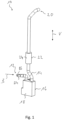
- the fuel cell exhaust system 10 includes an inlet area 12 in which fuel cell exhaust B can enter a fuel cell exhaust line 14.
- the fuel cell exhaust system 10 includes, following the inlet area 12, a separation unit 16 with an in Fig. 1 cut or open separated separation unit housing 18.
- the fuel cell exhaust line 14 passes through the separation unit housing 18 and extends essentially upwards from the separation unit housing 18 in a vertical direction V when the fuel cell exhaust system 10 is installed in a vehicle.
- the fuel cell exhaust gas B leaves the fuel cell exhaust system 10 in an exit area 20.
- the silencer unit 22 comprises a tubular silencer housing 24, which surrounds the length section 26 of the fuel cell exhaust line 14 located in the area of the silencer unit 22. Openings 32, 34 are provided in the longitudinal section 26 in association with two silencer chambers 28, 30 delimited by the silencer unit housing 24, so that there is a connection between the internal volume of the fuel cell exhaust line 14 in the length region 26 and the silencer chambers 28, 30.
- the silencer chambers 28, 30 can be separated from one another by a partition 36. It should be noted that, as in Fig.
- silencer unit 22 in Fig. 3 is only shown as an example and could also be configured in a different form in a very understandable way.
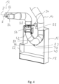
- the fuel cell exhaust line 14 leads with a tubular upstream line section 38, for example with a circular cross section and elongated in the direction of a flow center axis S, downstream of the inlet region 12 into the separation unit housing 18.
- a downstream line section adjoins the upstream line section 38 42 of the fuel cell exhaust line 14.
- the downstream line section 42 is positioned with an upstream end region 46 thereof engaging in a downstream end region 48 of the upstream line section 38.
- the downstream end region 48 of the upstream line section 38 is along the flow center axis S, which is essentially can also correspond to the center axis of the rectilinearly extending upstream line section 38, essentially conically widening.
- downstream line section 42 is in its upstream end region 46, which extends into the downstream end region 48 of the upstream line section 38, along the flow center axis S and in the direction of an Abas main flow direction H, in which the fuel cell exhaust gas B flows through the upstream line section 38, preferably in Essentially designed to expand conically.
- a ring-like first liquid discharge opening 50 is formed between the end sections 46, 48, which widen radially in a substantially complementary manner to one another, via which the fuel cell exhaust line 14 is open to the interior 40 of the separation unit housing 18.
- the fuel cell exhaust line 14 can be covered by a housing element 52, which in its lower area in the vertical direction V faces the interior 40 of the separation unit housing 18 can be open.
- a swirl current generating unit 54 is arranged upstream of the first liquid discharge opening 50 or the radially expanding downstream end region 48 of the upstream line section 38.
- the swirl flow generating unit 54 comprises a plurality of flow deflection elements 56 which are arranged one after the other around the flow center axis S in the circumferential direction, are designed like blades and extend essentially radially.
- the flow deflection elements 56 are positioned with respect to the main exhaust gas flow direction H, i.e.
- swirl current generating units are used as mixers, for example, in exhaust systems of diesel internal combustion engines.
- the exhaust gas of a diesel internal combustion engine flowing in such an exhaust system is swirled by the swirl flow generated in this way, so that an efficient mixing of the exhaust gas with the reducing agent injected into it, for example a urea / water solution, is generated and the mixture thus generated of exhaust gas and Reducing agent is introduced into an SCR catalyst unit.
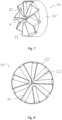
- the Fig. 7-9 show in more detail an embodiment example of the swirl current generation unit 54 that can be used in the fuel cell exhaust system 10.
- This can, for example, be bent in one piece from a sheet metal material and comprises a ring-like or essentially cylindrical body 55, with which the swirl current generation unit 68, for example, on the upstream line section 38 can be held.
- the flow deflection elements 56 which are designed like blades and are arranged one after the other in the circumferential direction, extend radially inwards, so that, for example, their radially inner end regions partially overlap in the circumferential direction.
- the flow deflection elements 56 are positioned with respect to the main exhaust gas flow direction H, i.e.
- the swirl current generating unit 54 can be constructed with plastic material. This leads to a lightweight structure that can be manufactured inexpensively, in which the swirl current generating unit 54 has a high level of corrosion resistance, particularly with regard to the water contained in the fuel cell exhaust gas.
- the extent of the deflection in the circumferential direction and thus the extent of the swirl flow generated, but at the same time also the extent of the flow caused by the Flow damming generated by flow deflection elements 56 depends on the angle of attack of the flow deflection elements 56 with respect to the main exhaust gas flow direction H.
- the flow deflection elements 56 are angled comparatively less, i.e. oriented more in the direction of the main exhaust gas flow direction H, so that a less strong deflection of the fuel cell exhaust gas flow in the circumferential direction is generated.
- FIG. 9 shows an embodiment of the swirl current generation unit 54, in which the flow deflection elements 56, which are also further extended in the circumferential direction, are positioned more strongly with respect to the main exhaust gas flow direction.
- the fuel cell exhaust gas flow is deflected more in the circumferential direction, which contributes to an increased centrifugal force acting on liquid particles contained in the fuel cell exhaust gas.
- the liquid-enriched part of the fuel cell exhaust gas flow enters the first liquid discharge opening 50, so that in particular the liquid carried in this part of the fuel cell exhaust gas flow also reaches the interior 40 and is thus extracted from the remaining part of the fuel cell exhaust gas stream, which enters the downstream line section 42 depleted of liquid.
- a liquid collecting region 62 is formed in a lower region of the separator unit housing 18 in the vertical direction V.
- the liquid collecting area 62 is designed with an upwardly open, bowl-like collecting container 64, which is inserted into the lower area of the interior 40 of the separator unit housing 18.
- a first liquid drain opening 68 is formed, via which liquid can be discharged from the separator unit housing 18.
- a valve can be assigned to the drain connection 66 in order to release liquid at defined times and to feed it back into the fuel cell process, for example.
- a second liquid drain opening 72 closed by a closing element 70 can be provided, via which the separating unit housing 18 can be completely emptied, for example when carrying out maintenance work.
- an electrically excitable heating unit 74 for example a heating coil or the like, can be provided in the liquid collection area 62, for example on a bottom area of the liquid collection container 64 or the separation unit housing 18.
- This heating unit 74 can be used to heat the liquid accumulating in the liquid collecting area 62 in order to prevent it from freezing, especially at comparatively low ambient temperatures, or in order to be able to release liquid from the liquid collecting area 62 even in the event of frost or low ambient temperatures.
- the liquid collection area 62 can also be used without the liquid collection container 64 could be designed and the discharge connection 66 can be formed, for example, directly on the separation unit housing 18.
- the downstream line section 42 is formed in its length region extending in the interior 40 of the separation unit housing 18 with a knee-like bend region 80, which forms a bend apex 82 positioned or to be positioned at the bottom in the vertical direction V.
- the second liquid discharge opening 78 is arranged, so that liquid accumulating downstream of the opening area 44, for example due to condensation, accumulates in the deepest area of the fuel cell exhaust line 14 downstream of the opening area 44 and towards the liquid collection area 62 from the fuel cell exhaust line 14 can exit.
- the need to extract liquid from the fuel cell exhaust gas B in particular in order to be able to continue using it in fuel cell operation, primarily exists when the process gas emerging from the cathode region of a fuel cell, i.e. the cathode exhaust gas K, passes through the fuel cell exhaust gas B
- Fuel cell exhaust system is routed. At the beginning of operation of a fuel cell system, it may be necessary to purge the anode region of a fuel cell with gas. This gas, which may still be present in the anode area, can be passed into the fuel cell exhaust system as anode exhaust gas A and released to the outside via this.
- the fuel cell exhaust line 14 can have two inlet connections 84, 86 in the inlet area 12, which are connected to the cathode area for receiving the cathode exhaust gas K and the anode area for receiving the anode exhaust gas A are connected or can be connected via corresponding valve arrangements in order to be able to specifically direct one or both of these exhaust gas streams through the fuel cell exhaust system 10.
- the anode regions or the cathode regions of several fuel cells or fuel cell stacks of a fuel cell system can be connected to the fuel cell exhaust system 10, for example via the inlet connections 84, 86.
- hydrogen-containing anode exhaust gas A is passed through the fuel cell exhaust system 14, there is basically the possibility that hydrogen reaches the interior 40 of the separation unit housing 18 via the first liquid delivery opening 50 or the second liquid delivery opening 78.
- the hydrogen which is significantly lighter compared to air or oxygen and nitrogen, will accumulate in the upper region of the interior 40 in the separation unit housing 18 in the vertical direction V.
- a hydrogen collection area 88 is therefore formed in this area of the separation unit housing 18 positioned at the top in the vertical direction V.
- the separation unit housing 18 is formed with a wall region 92 which tapers upward in the vertical direction V to an upper apex region 90, which conducts the upwardly volatile hydrogen to the upper apex region 90 in the manner of a funnel.
- a discharge pipe 94 connects to the wall region 92, which provides a preferably permanently open hydrogen discharge opening 96. Hydrogen introduced into the interior 40 is therefore guided into the apex region 90 due to its tendency to move upwards and released into the environment via the hydrogen discharge opening 96 in a fundamentally uncritical concentration.
- Providing the hydrogen collection area 88 formed with the essentially permanently open hydrogen discharge opening 96 further leads to the interior 40 of the separation unit housing 18 not being permanently closed. This avoids the creation of a dynamic pressure when the fuel cell exhaust gas flow is conducted through the fuel cell exhaust line 14 and thus also enables fuel cell exhaust gas B containing a high concentration of liquid to escape from the fuel cell exhaust line 14 via the first liquid discharge opening 50, essentially without backlog.
- the presence of the second liquid discharge opening 78 also prevents the creation of such a dynamic pressure in the interior 40 of the separation unit housing 18.
- the possibility is created of extracting liquid particles carried in the fuel cell exhaust, in particular water vapor or water droplets, from the fuel cell exhaust gas efficiently and with low back pressure or pressure loss.
- This enables significantly more efficient operation of a fuel cell, since it can be operated with lower compressor power, for example, due to the lower back pressure or flow resistance in the area of the fuel cell exhaust system.
- other system areas such as the fuel cell exhaust line, the separation unit and the silencer unit, can, for example, be constructed essentially completely with plastic material. This contributes to constructing a fuel cell exhaust system with a light weight and a low manufacturing cost. The construction with plastic material also leads to very good corrosion resistance and great freedom in the shape of various components of the fuel cell exhaust system.
- Such a fuel cell exhaust system can also be used in conjunction with fuel cell systems that are stationary or, for example, operated in ships or the like.
Landscapes
- Engineering & Computer Science (AREA)
- Chemical & Material Sciences (AREA)
- Chemical Kinetics & Catalysis (AREA)
- Sustainable Development (AREA)
- Sustainable Energy (AREA)
- Manufacturing & Machinery (AREA)
- Life Sciences & Earth Sciences (AREA)
- Electrochemistry (AREA)
- General Chemical & Material Sciences (AREA)
- Combustion & Propulsion (AREA)
- Mechanical Engineering (AREA)
- General Engineering & Computer Science (AREA)
- Fuel Cell (AREA)
- Exhaust Silencers (AREA)
Applications Claiming Priority (1)
| Application Number | Priority Date | Filing Date | Title |
|---|---|---|---|
| DE102022112683.8A DE102022112683A1 (de) | 2022-05-20 | 2022-05-20 | Brennstoffzellen-Abgasanlage |
Publications (2)
| Publication Number | Publication Date |
|---|---|
| EP4280321A2 true EP4280321A2 (fr) | 2023-11-22 |
| EP4280321A3 EP4280321A3 (fr) | 2024-03-13 |
Family
ID=86226448
Family Applications (1)
| Application Number | Title | Priority Date | Filing Date |
|---|---|---|---|
| EP23169659.2A Pending EP4280321A3 (fr) | 2022-05-20 | 2023-04-25 | Système d'échappement à pile à combustible |
Country Status (6)
| Country | Link |
|---|---|
| US (1) | US20230378500A1 (fr) |
| EP (1) | EP4280321A3 (fr) |
| JP (1) | JP7662705B2 (fr) |
| KR (1) | KR20230162554A (fr) |
| CN (1) | CN117096401A (fr) |
| DE (1) | DE102022112683A1 (fr) |
Families Citing this family (3)
| Publication number | Priority date | Publication date | Assignee | Title |
|---|---|---|---|---|
| CN120476489A (zh) * | 2023-12-12 | 2025-08-12 | 曼·胡默尔有限公司 | 用于氢燃料电池车辆的排气系统 |
| JP2025101952A (ja) * | 2023-12-26 | 2025-07-08 | 株式会社クボタ | 作業車両 |
| DE102024119112A1 (de) * | 2024-07-05 | 2026-01-08 | Purem GmbH | Brennstoffzellenabgasanlage, Brennstoffzellensystem und Verfahren zum Verringern des Wassergehalts in Brennstoffzellenabgas |
Family Cites Families (8)
| Publication number | Priority date | Publication date | Assignee | Title |
|---|---|---|---|---|
| US6579637B1 (en) * | 2000-05-31 | 2003-06-17 | General Motors Corporation | Fuel cell system having a compact water separator |
| JP2007268340A (ja) | 2006-03-30 | 2007-10-18 | Nissan Motor Co Ltd | 気液分離装置 |
| JP2014072096A (ja) * | 2012-09-28 | 2014-04-21 | Daihatsu Motor Co Ltd | 燃料電池システムの気液分離器 |
| US9437890B2 (en) | 2013-06-25 | 2016-09-06 | Ford Global Technologies, Llc | Purge assembly for a fuel cell system |
| DE102016221566A1 (de) | 2016-11-03 | 2018-05-03 | Bayerische Motoren Werke Aktiengesellschaft | Wasserabscheider zum Abscheiden von Wasser in einem Fahrzeug |
| CN110492146B (zh) * | 2019-07-17 | 2025-01-24 | 格罗夫氢能源科技集团有限公司 | 燃料电池排气排水装置 |
| DE102019214756A1 (de) | 2019-09-26 | 2021-04-01 | Robert Bosch Gmbh | Vorrichtung zur Abscheidung von Wasser aus einem Wasser-Dampf-Luft-Gemischstrom |
| US11211619B2 (en) * | 2019-10-11 | 2021-12-28 | GM Global Technology Operations LLC | Fuel cell architectures, aftertreatment systems, and control logic for exhaust water extraction |
-
2022
- 2022-05-20 DE DE102022112683.8A patent/DE102022112683A1/de active Pending
-
2023
- 2023-04-25 EP EP23169659.2A patent/EP4280321A3/fr active Pending
- 2023-05-16 CN CN202310546674.0A patent/CN117096401A/zh active Pending
- 2023-05-18 KR KR1020230064647A patent/KR20230162554A/ko active Pending
- 2023-05-19 US US18/320,501 patent/US20230378500A1/en active Pending
- 2023-05-19 JP JP2023082805A patent/JP7662705B2/ja active Active
Also Published As
| Publication number | Publication date |
|---|---|
| KR20230162554A (ko) | 2023-11-28 |
| JP7662705B2 (ja) | 2025-04-15 |
| US20230378500A1 (en) | 2023-11-23 |
| CN117096401A (zh) | 2023-11-21 |
| EP4280321A3 (fr) | 2024-03-13 |
| JP2023171352A (ja) | 2023-12-01 |
| DE102022112683A1 (de) | 2023-11-23 |
Similar Documents
| Publication | Publication Date | Title |
|---|---|---|
| EP4280321A2 (fr) | Système d'échappement à pile à combustible | |
| EP4280324A2 (fr) | Système d'échappement à pile à combustible | |
| EP2502300B1 (fr) | Système de pile à combustible avec séparateur gaz-liquide dans le boucle de recirculation anodique | |
| EP3717822A1 (fr) | Séparateur gaz-liquide servant à séparer au moins un constituant liquide d'un constituant gazeux | |
| DE102006038700B4 (de) | Vorrichtung zur Abscheidung von Flüssigkeiten aus Gasen | |
| EP4422775B1 (fr) | Dispositif de séparation, compresseur avec un dispositif de séparation et installation de réfrigération avec un dispositif de séparation | |
| DE102012023682A1 (de) | Flüssigkeitsabscheider für ein Brennstoffzellensystem | |
| WO2009138384A1 (fr) | Séparateur pour une ventilation de carter de vilebrequin d’un moteur à combustion interne | |
| EP0946251A2 (fr) | Dispositif pour la separation de liquides et/ou de matieres solides ou de gaz ayant un autre poids specifique, a partir d'un flux gazeux | |
| DE10007522B4 (de) | Verfahren zur Trennung von Kraftstoffdampf-Luft-Gemischen und Vorrichtung zur Durchführung dieses Verfahrens | |
| DE4040142A1 (de) | Kaelteanlage | |
| DE102004011176B4 (de) | Ölabscheider | |
| WO2024056134A1 (fr) | Section de guidage de gaz d'échappement d'un turbocompresseur de gaz, et turbocompresseur de gaz | |
| WO2024056133A1 (fr) | Dispositif de flux entrant d'un canal en spirale d'une section de guidage de gaz d'échappement d'un turbocompresseur de gaz et turbocompresseur de gaz | |
| DE102004011177B4 (de) | Zylinderkopfhaube mit Ölabscheider | |
| DE102011114732A1 (de) | Gasstrahlpumpe und Brennstoffzellensystem | |
| DE10129098A1 (de) | Verfahren und Vorrichtung zum Abscheiden von Flüssigkeit aus einem Gasstrom | |
| DE102022131312A1 (de) | Fluidabscheider und Brennstoffzellensystem mit einem Flüssigkeitsabscheider | |
| DE102015116022A1 (de) | Verfahren und Vorrichtung zum Abscheiden von Gas aus einem Ölgasgemisch | |
| DE102004022245B4 (de) | Brennstoffzellensystem und Verfahren zu dessen Betrieb | |
| DE102005027415B4 (de) | Ölabscheider für ein Kurbelgehäuse einer Brennkraftmaschine | |
| DE102017211675B3 (de) | Vorrichtung und Verfahren zur Vermeidung von Kondensatansammlung beim Aufladen einer Brennkraftmaschine | |
| DE102023101749B4 (de) | Mobiles Brennstoffzellensystem | |
| EP1337000A2 (fr) | Dispositif de piles à combustible | |
| EP4675717A1 (fr) | Système d'échappement de pile à combustible, système de pile à combustible et procédé de réduction de la teneur en eau dans le gaz d'échappement de pile à combustible |
Legal Events
| Date | Code | Title | Description |
|---|---|---|---|
| PUAI | Public reference made under article 153(3) epc to a published international application that has entered the european phase |
Free format text: ORIGINAL CODE: 0009012 |
|
| STAA | Information on the status of an ep patent application or granted ep patent |
Free format text: STATUS: THE APPLICATION HAS BEEN PUBLISHED |
|
| AK | Designated contracting states |
Kind code of ref document: A2 Designated state(s): AL AT BE BG CH CY CZ DE DK EE ES FI FR GB GR HR HU IE IS IT LI LT LU LV MC ME MK MT NL NO PL PT RO RS SE SI SK SM TR |
|
| PUAL | Search report despatched |
Free format text: ORIGINAL CODE: 0009013 |
|
| AK | Designated contracting states |
Kind code of ref document: A3 Designated state(s): AL AT BE BG CH CY CZ DE DK EE ES FI FR GB GR HR HU IE IS IT LI LT LU LV MC ME MK MT NL NO PL PT RO RS SE SI SK SM TR |
|
| RIC1 | Information provided on ipc code assigned before grant |
Ipc: H01M 8/0662 20160101ALI20240205BHEP Ipc: H01M 8/04291 20160101ALI20240205BHEP Ipc: H01M 8/04119 20160101AFI20240205BHEP |
|
| STAA | Information on the status of an ep patent application or granted ep patent |
Free format text: STATUS: REQUEST FOR EXAMINATION WAS MADE |
|
| 17P | Request for examination filed |
Effective date: 20240821 |
|
| RBV | Designated contracting states (corrected) |
Designated state(s): AL AT BE BG CH CY CZ DE DK EE ES FI FR GB GR HR HU IE IS IT LI LT LU LV MC ME MK MT NL NO PL PT RO RS SE SI SK SM TR |