EP4279681B1 - Window frame with filling profile - Google Patents
Window frame with filling profile Download PDFInfo
- Publication number
- EP4279681B1 EP4279681B1 EP23173318.9A EP23173318A EP4279681B1 EP 4279681 B1 EP4279681 B1 EP 4279681B1 EP 23173318 A EP23173318 A EP 23173318A EP 4279681 B1 EP4279681 B1 EP 4279681B1
- Authority
- EP
- European Patent Office
- Prior art keywords
- stile
- wall
- frame
- window
- window frame
- Prior art date
- Legal status (The legal status is an assumption and is not a legal conclusion. Google has not performed a legal analysis and makes no representation as to the accuracy of the status listed.)
- Active
Links
Images

Classifications
-
- E—FIXED CONSTRUCTIONS
- E04—BUILDING
- E04D—ROOF COVERINGS; SKY-LIGHTS; GUTTERS; ROOF-WORKING TOOLS
- E04D13/00—Special arrangements or devices in connection with roof coverings; Protection against birds; Roof drainage ; Sky-lights
- E04D13/03—Sky-lights; Domes; Ventilating sky-lights
- E04D13/035—Sky-lights; Domes; Ventilating sky-lights characterised by having movable parts
- E04D13/0351—Sky-lights; Domes; Ventilating sky-lights characterised by having movable parts the parts pivoting about a fixed axis
- E04D13/0354—Sky-lights; Domes; Ventilating sky-lights characterised by having movable parts the parts pivoting about a fixed axis the parts being flat
-
- E—FIXED CONSTRUCTIONS
- E04—BUILDING
- E04D—ROOF COVERINGS; SKY-LIGHTS; GUTTERS; ROOF-WORKING TOOLS
- E04D13/00—Special arrangements or devices in connection with roof coverings; Protection against birds; Roof drainage ; Sky-lights
- E04D13/03—Sky-lights; Domes; Ventilating sky-lights
-
- E—FIXED CONSTRUCTIONS
- E04—BUILDING
- E04D—ROOF COVERINGS; SKY-LIGHTS; GUTTERS; ROOF-WORKING TOOLS
- E04D13/00—Special arrangements or devices in connection with roof coverings; Protection against birds; Roof drainage ; Sky-lights
- E04D13/03—Sky-lights; Domes; Ventilating sky-lights
- E04D13/0305—Supports or connecting means for sky-lights of flat or domed shape
- E04D13/031—Supports or connecting means for sky-lights of flat or domed shape characterised by a frame for connection to an inclined roof
-
- E—FIXED CONSTRUCTIONS
- E04—BUILDING
- E04D—ROOF COVERINGS; SKY-LIGHTS; GUTTERS; ROOF-WORKING TOOLS
- E04D13/00—Special arrangements or devices in connection with roof coverings; Protection against birds; Roof drainage ; Sky-lights
- E04D13/03—Sky-lights; Domes; Ventilating sky-lights
- E04D13/035—Sky-lights; Domes; Ventilating sky-lights characterised by having movable parts
-
- E—FIXED CONSTRUCTIONS
- E06—DOORS, WINDOWS, SHUTTERS, OR ROLLER BLINDS IN GENERAL; LADDERS
- E06B—FIXED OR MOVABLE CLOSURES FOR OPENINGS IN BUILDINGS, VEHICLES, FENCES OR LIKE ENCLOSURES IN GENERAL, e.g. DOORS, WINDOWS, BLINDS, GATES
- E06B3/00—Window sashes, door leaves, or like elements for closing wall or like openings; Layout of fixed or moving closures, e.g. windows in wall or like openings; Features of rigidly-mounted outer frames relating to the mounting of wing frames
- E06B3/04—Wing frames not characterised by the manner of movement
- E06B3/06—Single frames
- E06B3/08—Constructions depending on the use of specified materials
- E06B3/20—Constructions depending on the use of specified materials of plastics
- E06B3/22—Hollow frames
Definitions
- the object of the invention is a welded thermoplastic frame for a roof window with an infill profile.
- a skylight with at least one plastic frame was disclosed under patent GB2099899A .
- the skylight frame is made of stiles connected at frame corners using a welding method.
- Stiles of previously disclosed welded window frames include chambers and comprises a cross-sections which make it possible to weld their edges in frame corners whilst maintaining its tightness.
- the invention relates to a window frame for a roof window, comprising a stiles with cross-sections which make it possible to weld them to one another.
- the window frame is constructed in a way which also ensures unhindered insertion and extraction of roof window sash seated on hinges in the window frame.
- its sash pivot around the horizontal axis so that sash lower stile is raised upwards above the window frame lower stile. Therefore, the sash lower stile moves in circular motion relative to the window frame, which requires a greater gap between the window frame and sash lower stiles than between the window frame and sash side stiles, where the sash side stiles move parallel relative to the window frame side stiles.
- an infill profile according to claim 1 was used which at least partially covers the gap in the lower section of the window and facilitates the aforementioned unhindered sash insertion and extraction into and out of the window frame and makes it possible to weld frame stiles together.
- the window frame according to the invention is a frame comprising an upper stile, a lower stile and two side stiles.
- the frame stiles are made from plastic profiles which comprise their walls: an outer wall, an inner wall, a top wall and a bottom wall.
- the stile bottom wall comprises a lining groove for the edge of roof window lining.
- the window frame stile chambers may include metal strengthening profiles, preferably at least partially flush with frame stile outer wall as well as insulation profiles.
- the window frame is designed for a window, and in particular a roof window which also includes an sash frame with a glass unit.
- the sash frame referred to as the sash, is constructed out of an upper, a lower and two side stiles, which, when the window is in its closed position, are flush with corresponding window frame stiles according to the invention.
- the window frame comprises an infill profile, mounted to the lower stile inner wall.
- the infill profile is designed to fill the gap between the frame lower stile and lower stile of the sash which is ultimately to be seated in the said window frame.
- the infill profile is preferably made out of plastic and comprises a longitudinal edge and it is not longer than the frame stile to which it is attached. Once installed, at least one infill profile longitudinal edge is in the frame lower stile longitudinal socket, and the infill profile overlaps at least partially the sash lower stile or does not overlap the sash bottom stile when the window is closed. This stems from the position of the window frame lower stile longitudinal socket.
- the lower stile with an infill profile includes a latching cube attached to a strengthening plate in a chamber of that stile. The latching cube works with the roof window sash handle latch. The latching cube is partially seated on the infill profile or is fully seated on the infill profile.
- stiles of the frame window according to the invention can be welded together and a sash may be seated in that frame, which is inserted and extracted unhindered into and out of the window frame when closing and opening the roof window.
- the infill profile also ensures that the gap between the sash and the jamb is as small as possible and preferably the same from all sides in the window closed position, and the latching cube seated at least partially on the infill profile makes it possible to lock the sash in the window frame.
- this invention may be used in particular for small windows for which the radius of the circle constituting sash extraction path from the window frame is smaller than for larger windows. That requires a larger gap between sash and window frame lower stiles and a larger infill profile, and connecting the latching cube with the infill profile provides such an opportunity whilst at the same time making it possible to lock the sash in the window frame by latching the handle in the latching cube.
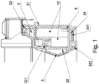
- FIG. 1 lower stile with infill profile
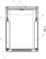
- Fig. 2 spatial view of window frame
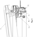
- Fig. 3 top view of window frame.
- the plastic window frame comprising an upper stile 1, a side stiles 2 and a lower stile 3.
- Each stile comprising an outer wall 31, an inner wall 32, joining a top wall 33 and a bottom wall 34 with chambers 4 in between stile walls.
- Stile wall edges are welded to each other.
- Frame lower stile 3 additionally comprises an infill profile 5 seated in longitudinal grooves 321, 322 of inner wall 32.
- Frame stile chambers 4 house strengthening profiles 6 and insulation profiles 10.
- Latching cube 7 is in infill profile 5 and lower stile inner wall 32, it is attached to a plate and strengthens the inside of frame lower stile 3.
- the latching cube works with sash 11 handle latch designed to be seated in a window frame.
- Stile bottom walls 34 comprises a lining groove 341 for the interior lining around the window and window frame.
- the window also comprises a set of shielding profiles, with frame side stiles shielding profiles 8 seated on frame side stile 2 top wall.
- the window frame also includes ventilation channel 9 in upper stile 1.
- the ventilation channel terminates with vent 91 in upper stile 1 inner wall which constitutes the ventilation channel outlet.
- the ventilation channel inlet is in upper stile 1 top wall.
- the ventilation channel inlet is shielded by the window frame hood which is one of the shielding profiles from the set of profiles shielding the window with frame according to the invention.
Landscapes
- Engineering & Computer Science (AREA)
- Civil Engineering (AREA)
- Structural Engineering (AREA)
- Architecture (AREA)
- Wing Frames And Configurations (AREA)
- Joining Of Corner Units Of Frames Or Wings (AREA)
Description
- The object of the invention is a welded thermoplastic frame for a roof window with an infill profile.
- A skylight with at least one plastic frame was disclosed under patent
GB2099899A - The invention relates to a window frame for a roof window, comprising a stiles with cross-sections which make it possible to weld them to one another. The window frame is constructed in a way which also ensures unhindered insertion and extraction of roof window sash seated on hinges in the window frame. When opening the roof window, its sash pivot around the horizontal axis so that sash lower stile is raised upwards above the window frame lower stile. Therefore, the sash lower stile moves in circular motion relative to the window frame, which requires a greater gap between the window frame and sash lower stiles than between the window frame and sash side stiles, where the sash side stiles move parallel relative to the window frame side stiles. As for aesthetic reasons the smallest possible gap between appropriate roof window frame and sash stiles is desired, an infill profile according to
claim 1 was used which at least partially covers the gap in the lower section of the window and facilitates the aforementioned unhindered sash insertion and extraction into and out of the window frame and makes it possible to weld frame stiles together. - The window frame according to the invention is a frame comprising an upper stile, a lower stile and two side stiles. The frame stiles are made from plastic profiles which comprise their walls: an outer wall, an inner wall, a top wall and a bottom wall. Once the frame is installed in a roof opening, the outer wall of the frame stiles is at least partially flush with the roof structure, whereas its inner wall is facing towards the frame inner opening. The top wall and the bottom wall join the inner and outer walls together making a stile profile with inner chambers. Once installed on a roof, the frame bottom wall faces towards the interior, whereas the top wall is on the opposite side and is shielded from the outside by the window shielding profiles. Furthermore, the stile bottom wall comprises a lining groove for the edge of roof window lining. When welding frame stiles, essentially all their walls are joined to each other. The window frame stile chambers may include metal strengthening profiles, preferably at least partially flush with frame stile outer wall as well as insulation profiles. The window frame is designed for a window, and in particular a roof window which also includes an sash frame with a glass unit. The sash frame, referred to as the sash, is constructed out of an upper, a lower and two side stiles, which, when the window is in its closed position, are flush with corresponding window frame stiles according to the invention. The window frame comprises an infill profile, mounted to the lower stile inner wall. The infill profile is designed to fill the gap between the frame lower stile and lower stile of the sash which is ultimately to be seated in the said window frame. The infill profile is preferably made out of plastic and comprises a longitudinal edge and it is not longer than the frame stile to which it is attached. Once installed, at least one infill profile longitudinal edge is in the frame lower stile longitudinal socket, and the infill profile overlaps at least partially the sash lower stile or does not overlap the sash bottom stile when the window is closed. This stems from the position of the window frame lower stile longitudinal socket. The lower stile with an infill profile includes a latching cube attached to a strengthening plate in a chamber of that stile. The latching cube works with the roof window sash handle latch. The latching cube is partially seated on the infill profile or is fully seated on the infill profile.
- For windows with a plastic window frame and stiles welded together, it is desirable for walls of joined stiles to be identical. Therefore, without changing the window frame lower style shape, but by mounting an infill profile on it, stiles of the frame window according to the invention can be welded together and a sash may be seated in that frame, which is inserted and extracted unhindered into and out of the window frame when closing and opening the roof window. The infill profile also ensures that the gap between the sash and the jamb is as small as possible and preferably the same from all sides in the window closed position, and the latching cube seated at least partially on the infill profile makes it possible to lock the sash in the window frame. As the latching cube overlaps the infill profile, this invention may be used in particular for small windows for which the radius of the circle constituting sash extraction path from the window frame is smaller than for larger windows. That requires a larger gap between sash and window frame lower stiles and a larger infill profile, and connecting the latching cube with the infill profile provides such an opportunity whilst at the same time making it possible to lock the sash in the window frame by latching the handle in the latching cube.
- The illustration depicts the solution, with given figures showing the following:
Fig. 1 lower stile with infill profile,Fig. 2 spatial view of window frame,Fig. 3 top view of window frame. - The plastic window frame comprising an
upper stile 1, aside stiles 2 and alower stile 3. Each stile comprising anouter wall 31, aninner wall 32, joining atop wall 33 and abottom wall 34 withchambers 4 in between stile walls. Stile wall edges are welded to each other. Framelower stile 3 additionally comprises aninfill profile 5 seated inlongitudinal grooves inner wall 32.Frame stile chambers 4 house strengtheningprofiles 6 andinsulation profiles 10. Latchingcube 7 is ininfill profile 5 and lower stileinner wall 32, it is attached to a plate and strengthens the inside of framelower stile 3. The latching cube works with sash 11 handle latch designed to be seated in a window frame. Whilst opening the window, sash 111 lower stile moves in circular motion relative to the window framelower stile 3.Stile bottom walls 34 comprises alining groove 341 for the interior lining around the window and window frame. The window also comprises a set of shielding profiles, with frame sidestiles shielding profiles 8 seated onframe side stile 2 top wall. The window frame also includesventilation channel 9 inupper stile 1. The ventilation channel terminates withvent 91 inupper stile 1 inner wall which constitutes the ventilation channel outlet. The ventilation channel inlet is inupper stile 1 top wall. The ventilation channel inlet is shielded by the window frame hood which is one of the shielding profiles from the set of profiles shielding the window with frame according to the invention.
Claims (10)
- Window frame for a roof window comprising an upper stile (1), a lower stile (3) and two side stiles (2), constructed out of thermoplastic profiles welded together at corners of the frame, said stile profiles (1, 2, comprise an outer wall (31), an inner wall (32) as well as a top wall (33) and a bottom wall (34) with at least one chamber (4) in between them, wherein stile inner wall (32) is facing the interior frame opening, and outer wall (31), once installed, is partially flush with the roof structure
said window frame being characterized in that it includes an infill profile (5) attached to the lower stile (3) inner wall (32), said infill profile (5) being designed to fill the gap between the frame lower stile (3) and lower stile of the sash seated in the window frame,such that unhindered sash insertion and extraction into and out of the window frame is provided, and the window frame being further characterized in that it comprises a latching cube (7) seated at least partially on the infill profile (5). - The window frame according to claim 1 characterized in that latching cube (7) is fully seated on infill profile (5).
- The frame according to claim 1 or 2 characterized in that the inner wall (32) of lower stile with infill profile (5) comprises at least one longitudinal socket (321, 322) for infill profile (5) longitudinal arm for attaching infill profile (5) on lower stile (3).
- The frame according to patent claim 1 or 2, or 3 characterized in that the infill profile overlaps at least partially the sash lower stile.
- The frame according to patent claim 1 or 2, or 3 characterized in that the infill profile does not overlap the sash lower stile when the window is closed.
- The frame according to patent claim 1 or 2, or 3, or 4, or 5 characterized in that strengthening profile (6) is located between frame stile outer wall and inner wall (32) which in particular is flush with at least the stile outer wall (31).
- The frame according to claim 1 or 2, or 3, or 4, or 5, or 6 characterized in that latching cube (7) attached to strengthening plate inside lower stile (3) is located in lower stile (3) with infill profile (5).
- The window frame according to patent claim 1 or 2, or 3, or 4, or 5, or 6, or 7 characterized in that insulation profiles (10) are located in frame stile chambers (4).
- The window frame according to patent claim 1 or 2, or 3, or 4, or 5, or 6, or 7, or 8 characterized in that stile bottom wall (34) comprises lining groove (341) for the edge of roof window lining.
- The window frame according to claim 1 characterized in that upper stile (1) includes ventilation channel (9), terminating with vent (91) in upper stile (1) inner wall.
Applications Claiming Priority (1)
| Application Number | Priority Date | Filing Date | Title |
|---|---|---|---|
| PL441213A PL248508B1 (en) | 2022-05-18 | 2022-05-18 | Window frame with filling profile |
Publications (3)
| Publication Number | Publication Date |
|---|---|
| EP4279681A1 EP4279681A1 (en) | 2023-11-22 |
| EP4279681B1 true EP4279681B1 (en) | 2025-05-07 |
| EP4279681C0 EP4279681C0 (en) | 2025-05-07 |
Family
ID=86605768
Family Applications (1)
| Application Number | Title | Priority Date | Filing Date |
|---|---|---|---|
| EP23173318.9A Active EP4279681B1 (en) | 2022-05-18 | 2023-05-15 | Window frame with filling profile |
Country Status (2)
| Country | Link |
|---|---|
| EP (1) | EP4279681B1 (en) |
| PL (1) | PL248508B1 (en) |
Families Citing this family (1)
| Publication number | Priority date | Publication date | Assignee | Title |
|---|---|---|---|---|
| PL131720U1 (en) * | 2023-10-09 | 2025-04-14 | Fakro Pp Spółka Z Ograniczoną Odpowiedzialnością | Plastic roof window |
Citations (16)
| Publication number | Priority date | Publication date | Assignee | Title |
|---|---|---|---|---|
| GB2099899A (en) | 1981-06-04 | 1982-12-15 | Wasco Products | Skylight construction |
| US5414962A (en) | 1990-11-09 | 1995-05-16 | Chelsea Industries, Inc. | Removable sash window construction having releasable guide members |
| DE202005020240U1 (en) | 2005-07-25 | 2006-12-07 | Frey, Inge | Bottom cross sill for windows and doors has closing plate matching shape of adjoining profiled cover aligned flush gap-free with same for seamless seal |
| EP1870532A2 (en) | 2006-06-22 | 2007-12-26 | The Metal Window Co. Ltd. | Rooflight |
| EP1932997A2 (en) | 2006-12-11 | 2008-06-18 | SYLID Systemlogistik und Industriedienstleistung GmbH | Upper closure of a threshold, closure system and threshold |
| EP2150658B1 (en) | 2007-04-27 | 2011-07-20 | Fakro PP Spolka Z O.O. | Roof window with air supply channel |
| EP2426303A2 (en) | 2010-09-06 | 2012-03-07 | FAKRO PP Spolka z o.o. | Metal reinforced plastic window frame |
| EP2546450A2 (en) | 2011-07-13 | 2013-01-16 | Dempsey Dyer Ltd | Apparatus, system and method for joining sub-frame members |
| EP2740853A1 (en) | 2012-12-07 | 2014-06-11 | Keystone Lintels Limited | A roof window with a locking apparatus |
| EP2826934A2 (en) | 2013-07-19 | 2015-01-21 | FAKRO PP Sp. z o.o. | Deadbolt socket assembly in a frame, having an increased break-in resistance |
| EP2408978B1 (en) | 2008-12-19 | 2015-05-06 | FAKRO PP Spolka z o.o. | A window frame, in particular a roof window frame, provided with a bolt socket unit |
| DE102016124443A1 (en) | 2015-12-15 | 2017-06-22 | Profine Gmbh | Method for connecting two hollow chamber profiles of different cross-section |
| EP3252249A1 (en) | 2016-05-30 | 2017-12-06 | VKR Holding A/S | A roof window refurbishment system and method for refurbishing a roof window |
| EP3181795B1 (en) | 2015-12-15 | 2018-08-08 | Profine GmbH | Method for connecting two holow-chamber sections having different cross-sections |
| EP3578729A1 (en) | 2018-06-06 | 2019-12-11 | VKR Holding A/S | Roof window with improved handle |
| EP3916187A1 (en) | 2020-05-29 | 2021-12-01 | VKR Holding A/S | A roof window installation system, and a method of installing a roof window |
Family Cites Families (2)
| Publication number | Priority date | Publication date | Assignee | Title |
|---|---|---|---|---|
| US4514943A (en) * | 1980-08-04 | 1985-05-07 | Wasco Products, Inc. | Thermal break skylight |
| US7296388B2 (en) * | 2003-08-12 | 2007-11-20 | Valentz Arthur J | Skylight having a molded plastic frame |
-
2022
- 2022-05-18 PL PL441213A patent/PL248508B1/en unknown
-
2023
- 2023-05-15 EP EP23173318.9A patent/EP4279681B1/en active Active
Patent Citations (16)
| Publication number | Priority date | Publication date | Assignee | Title |
|---|---|---|---|---|
| GB2099899A (en) | 1981-06-04 | 1982-12-15 | Wasco Products | Skylight construction |
| US5414962A (en) | 1990-11-09 | 1995-05-16 | Chelsea Industries, Inc. | Removable sash window construction having releasable guide members |
| DE202005020240U1 (en) | 2005-07-25 | 2006-12-07 | Frey, Inge | Bottom cross sill for windows and doors has closing plate matching shape of adjoining profiled cover aligned flush gap-free with same for seamless seal |
| EP1870532A2 (en) | 2006-06-22 | 2007-12-26 | The Metal Window Co. Ltd. | Rooflight |
| EP1932997A2 (en) | 2006-12-11 | 2008-06-18 | SYLID Systemlogistik und Industriedienstleistung GmbH | Upper closure of a threshold, closure system and threshold |
| EP2150658B1 (en) | 2007-04-27 | 2011-07-20 | Fakro PP Spolka Z O.O. | Roof window with air supply channel |
| EP2408978B1 (en) | 2008-12-19 | 2015-05-06 | FAKRO PP Spolka z o.o. | A window frame, in particular a roof window frame, provided with a bolt socket unit |
| EP2426303A2 (en) | 2010-09-06 | 2012-03-07 | FAKRO PP Spolka z o.o. | Metal reinforced plastic window frame |
| EP2546450A2 (en) | 2011-07-13 | 2013-01-16 | Dempsey Dyer Ltd | Apparatus, system and method for joining sub-frame members |
| EP2740853A1 (en) | 2012-12-07 | 2014-06-11 | Keystone Lintels Limited | A roof window with a locking apparatus |
| EP2826934A2 (en) | 2013-07-19 | 2015-01-21 | FAKRO PP Sp. z o.o. | Deadbolt socket assembly in a frame, having an increased break-in resistance |
| DE102016124443A1 (en) | 2015-12-15 | 2017-06-22 | Profine Gmbh | Method for connecting two hollow chamber profiles of different cross-section |
| EP3181795B1 (en) | 2015-12-15 | 2018-08-08 | Profine GmbH | Method for connecting two holow-chamber sections having different cross-sections |
| EP3252249A1 (en) | 2016-05-30 | 2017-12-06 | VKR Holding A/S | A roof window refurbishment system and method for refurbishing a roof window |
| EP3578729A1 (en) | 2018-06-06 | 2019-12-11 | VKR Holding A/S | Roof window with improved handle |
| EP3916187A1 (en) | 2020-05-29 | 2021-12-01 | VKR Holding A/S | A roof window installation system, and a method of installing a roof window |
Non-Patent Citations (5)
| Title |
|---|
| D18 - EUROPEAN SEARCH REPORT FOR THE EUROPEAN PATENT APPLICATION |
| D19 - THE EUROPEAN SEARCH OPINION FOR THE EUROPEAN PATENT APPLICATION |
| D20 - PATENTEE RESPONSE TO THE EUROPEAN SEARCH OPINION |
| OLAF ROLF: "Moderne Fenstertechnik - Werkstoff, Konstruktionen und Anforderungen", 1 January 1993, VERLAG MODERNE INDUSTRIE, München, Germany, ISBN: 3-478-93099-5, article OLAF ROLF: "Der Bau von Fenstern", pages: 35 - 43, XP009565871 |
| OLAF ROLF: "Moderne Fenstertechnik - Werkstoff, Konstruktionen und Anforderungen", 1 January 1993, VERLAG MODERNE INDUSTRIE, München, Germany, ISBN: 3-478-93099-5, article OLAF ROLF: "Grundlagen der modernen Fenstertechnik", pages: 19 - 34, XP009565872 |
Also Published As
| Publication number | Publication date |
|---|---|
| PL441213A1 (en) | 2023-11-20 |
| EP4279681A1 (en) | 2023-11-22 |
| PL248508B1 (en) | 2025-12-22 |
| EP4279681C0 (en) | 2025-05-07 |
Similar Documents
| Publication | Publication Date | Title |
|---|---|---|
| US20150159428A1 (en) | Anti-sputtering sill system and method | |
| US20140145061A1 (en) | Brick moulding system for window frames and door frames and method of manufacture of same | |
| EP4279681B1 (en) | Window frame with filling profile | |
| KR101554922B1 (en) | Sistem windows with enhanced insulation and structure | |
| JP6954803B2 (en) | Joinery | |
| JP7066601B2 (en) | Resin frame and fittings | |
| JP2000120349A (en) | Double-hung window and door with double-hung window | |
| JP2002121969A (en) | Double-hung window | |
| EP4279680B1 (en) | Window frame with corners | |
| EP4279682A1 (en) | A roof window with at least one window frame and a flange of the window's frame lower rail | |
| GB2488042A (en) | Window frame assembly | |
| JP7041019B2 (en) | Joinery | |
| KR102044162B1 (en) | Fittings system for mixing a sash window and sliding window | |
| JP7071589B2 (en) | System fittings with casement windows | |
| KR101467244B1 (en) | Multiple Fittings for Building | |
| CN218150457U (en) | Novel integrated structure of mullion-free split window screen | |
| KR102086254B1 (en) | Ventilation window for System window | |
| JP7023153B2 (en) | Joinery | |
| GB2196041A (en) | Window frames | |
| US7841138B1 (en) | Plastic paneling on metallic door frame | |
| CN110552595A (en) | a panoramic door | |
| US20060156653A1 (en) | Window conversion unit | |
| JP3964339B2 (en) | Joinery frame design method | |
| JP3238374B2 (en) | Insulated door | |
| JP3017084B2 (en) | Ventilation frame mounting structure |
Legal Events
| Date | Code | Title | Description |
|---|---|---|---|
| PUAI | Public reference made under article 153(3) epc to a published international application that has entered the european phase |
Free format text: ORIGINAL CODE: 0009012 |
|
| STAA | Information on the status of an ep patent application or granted ep patent |
Free format text: STATUS: THE APPLICATION HAS BEEN PUBLISHED |
|
| AK | Designated contracting states |
Kind code of ref document: A1 Designated state(s): AL AT BE BG CH CY CZ DE DK EE ES FI FR GB GR HR HU IE IS IT LI LT LU LV MC ME MK MT NL NO PL PT RO RS SE SI SK SM TR |
|
| STAA | Information on the status of an ep patent application or granted ep patent |
Free format text: STATUS: REQUEST FOR EXAMINATION WAS MADE |
|
| 17P | Request for examination filed |
Effective date: 20240110 |
|
| RBV | Designated contracting states (corrected) |
Designated state(s): AL AT BE BG CH CY CZ DE DK EE ES FI FR GB GR HR HU IE IS IT LI LT LU LV MC ME MK MT NL NO PL PT RO RS SE SI SK SM TR |
|
| GRAP | Despatch of communication of intention to grant a patent |
Free format text: ORIGINAL CODE: EPIDOSNIGR1 |
|
| STAA | Information on the status of an ep patent application or granted ep patent |
Free format text: STATUS: GRANT OF PATENT IS INTENDED |
|
| GRAS | Grant fee paid |
Free format text: ORIGINAL CODE: EPIDOSNIGR3 |
|
| INTG | Intention to grant announced |
Effective date: 20250303 |
|
| GRAA | (expected) grant |
Free format text: ORIGINAL CODE: 0009210 |
|
| STAA | Information on the status of an ep patent application or granted ep patent |
Free format text: STATUS: THE PATENT HAS BEEN GRANTED |
|
| AK | Designated contracting states |
Kind code of ref document: B1 Designated state(s): AL AT BE BG CH CY CZ DE DK EE ES FI FR GB GR HR HU IE IS IT LI LT LU LV MC ME MK MT NL NO PL PT RO RS SE SI SK SM TR |
|
| REG | Reference to a national code |
Ref country code: GB Ref legal event code: FG4D |
|
| REG | Reference to a national code |
Ref country code: CH Ref legal event code: EP |
|
| REG | Reference to a national code |
Ref country code: IE Ref legal event code: FG4D |
|
| U01 | Request for unitary effect filed |
Effective date: 20250507 |
|
| U07 | Unitary effect registered |
Designated state(s): AT BE BG DE DK EE FI FR IT LT LU LV MT NL PT RO SE SI Effective date: 20250513 |
|
| U20 | Renewal fee for the european patent with unitary effect paid |
Year of fee payment: 3 Effective date: 20250610 |
|
| PG25 | Lapsed in a contracting state [announced via postgrant information from national office to epo] |
Ref country code: ES Free format text: LAPSE BECAUSE OF FAILURE TO SUBMIT A TRANSLATION OF THE DESCRIPTION OR TO PAY THE FEE WITHIN THE PRESCRIBED TIME-LIMIT Effective date: 20250507 |
|
| PG25 | Lapsed in a contracting state [announced via postgrant information from national office to epo] |
Ref country code: GR Free format text: LAPSE BECAUSE OF FAILURE TO SUBMIT A TRANSLATION OF THE DESCRIPTION OR TO PAY THE FEE WITHIN THE PRESCRIBED TIME-LIMIT Effective date: 20250808 Ref country code: NO Free format text: LAPSE BECAUSE OF FAILURE TO SUBMIT A TRANSLATION OF THE DESCRIPTION OR TO PAY THE FEE WITHIN THE PRESCRIBED TIME-LIMIT Effective date: 20250807 |
|
| PG25 | Lapsed in a contracting state [announced via postgrant information from national office to epo] |
Ref country code: PL Free format text: LAPSE BECAUSE OF FAILURE TO SUBMIT A TRANSLATION OF THE DESCRIPTION OR TO PAY THE FEE WITHIN THE PRESCRIBED TIME-LIMIT Effective date: 20250507 |
|
| PG25 | Lapsed in a contracting state [announced via postgrant information from national office to epo] |
Ref country code: HR Free format text: LAPSE BECAUSE OF FAILURE TO SUBMIT A TRANSLATION OF THE DESCRIPTION OR TO PAY THE FEE WITHIN THE PRESCRIBED TIME-LIMIT Effective date: 20250507 |
|
| PG25 | Lapsed in a contracting state [announced via postgrant information from national office to epo] |
Ref country code: RS Free format text: LAPSE BECAUSE OF FAILURE TO SUBMIT A TRANSLATION OF THE DESCRIPTION OR TO PAY THE FEE WITHIN THE PRESCRIBED TIME-LIMIT Effective date: 20250807 |
|
| PG25 | Lapsed in a contracting state [announced via postgrant information from national office to epo] |
Ref country code: IS Free format text: LAPSE BECAUSE OF FAILURE TO SUBMIT A TRANSLATION OF THE DESCRIPTION OR TO PAY THE FEE WITHIN THE PRESCRIBED TIME-LIMIT Effective date: 20250907 |
|
| PG25 | Lapsed in a contracting state [announced via postgrant information from national office to epo] |
Ref country code: SM Free format text: LAPSE BECAUSE OF FAILURE TO SUBMIT A TRANSLATION OF THE DESCRIPTION OR TO PAY THE FEE WITHIN THE PRESCRIBED TIME-LIMIT Effective date: 20250507 |
|
| PG25 | Lapsed in a contracting state [announced via postgrant information from national office to epo] |
Ref country code: CZ Free format text: LAPSE BECAUSE OF FAILURE TO SUBMIT A TRANSLATION OF THE DESCRIPTION OR TO PAY THE FEE WITHIN THE PRESCRIBED TIME-LIMIT Effective date: 20250507 |
|
| PG25 | Lapsed in a contracting state [announced via postgrant information from national office to epo] |
Ref country code: SK Free format text: LAPSE BECAUSE OF FAILURE TO SUBMIT A TRANSLATION OF THE DESCRIPTION OR TO PAY THE FEE WITHIN THE PRESCRIBED TIME-LIMIT Effective date: 20250507 |
|
| PLBI | Opposition filed |
Free format text: ORIGINAL CODE: 0009260 |
|
| REG | Reference to a national code |
Ref country code: CH Ref legal event code: L10 Free format text: ST27 STATUS EVENT CODE: U-0-0-L10-L00 (AS PROVIDED BY THE NATIONAL OFFICE) Effective date: 20260218 |
|
| PG25 | Lapsed in a contracting state [announced via postgrant information from national office to epo] |
Ref country code: MC Free format text: LAPSE BECAUSE OF FAILURE TO SUBMIT A TRANSLATION OF THE DESCRIPTION OR TO PAY THE FEE WITHIN THE PRESCRIBED TIME-LIMIT Effective date: 20250507 |
|
| PLAX | Notice of opposition and request to file observation + time limit sent |
Free format text: ORIGINAL CODE: EPIDOSNOBS2 |
|
| 26 | Opposition filed |
Opponent name: VKR HOLDING A/S Effective date: 20260206 |