EP4279351A1 - Verfahren zur einstellung einer tempomatfunktion mit automatischer abstandseinstellung in einem einspurfahrzeug - Google Patents
Verfahren zur einstellung einer tempomatfunktion mit automatischer abstandseinstellung in einem einspurfahrzeug Download PDFInfo
- Publication number
- EP4279351A1 EP4279351A1 EP23159636.2A EP23159636A EP4279351A1 EP 4279351 A1 EP4279351 A1 EP 4279351A1 EP 23159636 A EP23159636 A EP 23159636A EP 4279351 A1 EP4279351 A1 EP 4279351A1
- Authority
- EP
- European Patent Office
- Prior art keywords
- vehicle
- track
- distance
- track vehicle
- threshold value
- Prior art date
- Legal status (The legal status is an assumption and is not a legal conclusion. Google has not performed a legal analysis and makes no representation as to the accuracy of the status listed.)
- Granted
Links
Images

Classifications
-
- B—PERFORMING OPERATIONS; TRANSPORTING
- B60—VEHICLES IN GENERAL
- B60W—CONJOINT CONTROL OF VEHICLE SUB-UNITS OF DIFFERENT TYPE OR DIFFERENT FUNCTION; CONTROL SYSTEMS SPECIALLY ADAPTED FOR HYBRID VEHICLES; ROAD VEHICLE DRIVE CONTROL SYSTEMS FOR PURPOSES NOT RELATED TO THE CONTROL OF A PARTICULAR SUB-UNIT
- B60W30/00—Purposes of road vehicle drive control systems not related to the control of a particular sub-unit, e.g. of systems using conjoint control of vehicle sub-units
- B60W30/14—Adaptive cruise control
- B60W30/16—Control of distance between vehicles, e.g. keeping a distance to preceding vehicle
-
- B—PERFORMING OPERATIONS; TRANSPORTING
- B60—VEHICLES IN GENERAL
- B60W—CONJOINT CONTROL OF VEHICLE SUB-UNITS OF DIFFERENT TYPE OR DIFFERENT FUNCTION; CONTROL SYSTEMS SPECIALLY ADAPTED FOR HYBRID VEHICLES; ROAD VEHICLE DRIVE CONTROL SYSTEMS FOR PURPOSES NOT RELATED TO THE CONTROL OF A PARTICULAR SUB-UNIT
- B60W40/00—Estimation or calculation of non-directly measurable driving parameters for road vehicle drive control systems not related to the control of a particular sub unit, e.g. by using mathematical models
- B60W40/02—Estimation or calculation of non-directly measurable driving parameters for road vehicle drive control systems not related to the control of a particular sub unit, e.g. by using mathematical models related to ambient conditions
- B60W40/06—Road conditions
-
- B—PERFORMING OPERATIONS; TRANSPORTING
- B60—VEHICLES IN GENERAL
- B60W—CONJOINT CONTROL OF VEHICLE SUB-UNITS OF DIFFERENT TYPE OR DIFFERENT FUNCTION; CONTROL SYSTEMS SPECIALLY ADAPTED FOR HYBRID VEHICLES; ROAD VEHICLE DRIVE CONTROL SYSTEMS FOR PURPOSES NOT RELATED TO THE CONTROL OF A PARTICULAR SUB-UNIT
- B60W2300/00—Indexing codes relating to the type of vehicle
- B60W2300/36—Cycles; Motorcycles; Scooters
-
- B—PERFORMING OPERATIONS; TRANSPORTING
- B60—VEHICLES IN GENERAL
- B60W—CONJOINT CONTROL OF VEHICLE SUB-UNITS OF DIFFERENT TYPE OR DIFFERENT FUNCTION; CONTROL SYSTEMS SPECIALLY ADAPTED FOR HYBRID VEHICLES; ROAD VEHICLE DRIVE CONTROL SYSTEMS FOR PURPOSES NOT RELATED TO THE CONTROL OF A PARTICULAR SUB-UNIT
- B60W2552/00—Input parameters relating to infrastructure
- B60W2552/05—Type of road, e.g. motorways, local streets, paved or unpaved roads
-
- B—PERFORMING OPERATIONS; TRANSPORTING
- B60—VEHICLES IN GENERAL
- B60W—CONJOINT CONTROL OF VEHICLE SUB-UNITS OF DIFFERENT TYPE OR DIFFERENT FUNCTION; CONTROL SYSTEMS SPECIALLY ADAPTED FOR HYBRID VEHICLES; ROAD VEHICLE DRIVE CONTROL SYSTEMS FOR PURPOSES NOT RELATED TO THE CONTROL OF A PARTICULAR SUB-UNIT
- B60W2554/00—Input parameters relating to objects
- B60W2554/80—Spatial relation or speed relative to objects
-
- B—PERFORMING OPERATIONS; TRANSPORTING
- B60—VEHICLES IN GENERAL
- B60W—CONJOINT CONTROL OF VEHICLE SUB-UNITS OF DIFFERENT TYPE OR DIFFERENT FUNCTION; CONTROL SYSTEMS SPECIALLY ADAPTED FOR HYBRID VEHICLES; ROAD VEHICLE DRIVE CONTROL SYSTEMS FOR PURPOSES NOT RELATED TO THE CONTROL OF A PARTICULAR SUB-UNIT
- B60W2554/00—Input parameters relating to objects
- B60W2554/80—Spatial relation or speed relative to objects
- B60W2554/801—Lateral distance
-
- B—PERFORMING OPERATIONS; TRANSPORTING
- B60—VEHICLES IN GENERAL
- B60W—CONJOINT CONTROL OF VEHICLE SUB-UNITS OF DIFFERENT TYPE OR DIFFERENT FUNCTION; CONTROL SYSTEMS SPECIALLY ADAPTED FOR HYBRID VEHICLES; ROAD VEHICLE DRIVE CONTROL SYSTEMS FOR PURPOSES NOT RELATED TO THE CONTROL OF A PARTICULAR SUB-UNIT
- B60W2554/00—Input parameters relating to objects
- B60W2554/80—Spatial relation or speed relative to objects
- B60W2554/802—Longitudinal distance
-
- B—PERFORMING OPERATIONS; TRANSPORTING
- B60—VEHICLES IN GENERAL
- B60W—CONJOINT CONTROL OF VEHICLE SUB-UNITS OF DIFFERENT TYPE OR DIFFERENT FUNCTION; CONTROL SYSTEMS SPECIALLY ADAPTED FOR HYBRID VEHICLES; ROAD VEHICLE DRIVE CONTROL SYSTEMS FOR PURPOSES NOT RELATED TO THE CONTROL OF A PARTICULAR SUB-UNIT
- B60W2754/00—Output or target parameters relating to objects
- B60W2754/10—Spatial relation or speed relative to objects
- B60W2754/30—Longitudinal distance
-
- B—PERFORMING OPERATIONS; TRANSPORTING
- B60—VEHICLES IN GENERAL
- B60Y—INDEXING SCHEME RELATING TO ASPECTS CROSS-CUTTING VEHICLE TECHNOLOGY
- B60Y2200/00—Type of vehicle
- B60Y2200/10—Road Vehicles
Definitions
- the invention relates to a method for setting a cruise control function with automatic distance adjustment in a single-track vehicle.
- Distance cruise control functions are known, with the help of which the current vehicle speed is automatically adjusted depending on the distance to a vehicle in front.
- the driver can set a target speed in the adaptive cruise control, whereby the actual vehicle speed can be lower and is based on the speed of the vehicle in front.
- the distance to the vehicle in front is usually recorded using a radar device in the vehicle.
- the method according to the invention relates to the setting of a cruise control function with automatic distance adjustment in a single-track vehicle.
- the single-track vehicle is in particular a motor-driven single-track vehicle, preferably a motor-driven two-wheeler such as a motorcycle or a motor scooter.
- the cruise control function When the cruise control function is activated, the speed of the single-track vehicle is automatically set to a target speed, with both acceleration and braking processes being carried out automatically. Due to the design as a cruise control function With automatic distance adjustment, the actual speed can be set depending on a vehicle in front, which is detected using a distance detection unit. The actual speed can be adjusted to the speed of the vehicle in front, with the following vehicle maintaining a speed-dependent distance from the vehicle in front.
- the method according to the invention can be used in a group trip of single-track vehicles.
- the cruise control function is activated with a specified target speed
- the distance between two single-track vehicles in front is first determined using the distance detection unit.
- the side distance characterizes the lateral distance transverse to the longitudinal direction between the two single-track vehicles in front.
- a threshold value is determined which is calculated as a function of the previously determined lateral distance between the two single-track vehicles in front.
- the single-track vehicle driving in front is used as the following target vehicle for the cruise control function in the event that the lateral distance between the ego vehicle and the single-track vehicle driving in front, in particular immediately, is less than or equal to the threshold value.
- This approach has the advantage that the cruise control function automatically decides whether it is a group trip and whether the ego vehicle follows a single-track vehicle in front as part of the group.
- the decision can be made with existing hardware for a cruise control function with automatic distance adjustment; no additional hardware is required. If it is automatically recognized that it is a group trip, this is also the case belongs to the ego vehicle, the ego vehicle follows a single-track vehicle in front that is part of the group. If, on the other hand, the evaluation shows that the conditions mentioned for the ego vehicle to participate in the group journey are not met, which is the case if the threshold value is exceeded, the speed in the ego vehicle is not adjusted to the speed of the single-track vehicle in front. In this case, particularly in the case of a higher target speed compared to the speed of the single-track vehicles in front, the ego vehicle is overtaken until the target speed is reached.
- the determination of the lateral distance both between the two single-track vehicles in front and between the ego vehicle and a single-track vehicle in front can be carried out using a distance detection unit, which is part of an adaptive cruise control device for carrying out the method.
- the distance detection unit is in particular a radar-based distance detection unit, with the help of which both the longitudinal distance between the ego vehicle and one or more vehicles in front as well as the lateral distance between two vehicles in front and between the ego vehicle and a vehicle in front can be determined .
- the resolution of the radar-based distance detection unit is good enough for determining both the longitudinal distance and the transverse distance.
- the method according to the invention can be applied to situations in which at least two single-track vehicles drive in front of the ego vehicle. If necessary, more than two single-track vehicles can be in front of the ego vehicle. With the help of the sensors in the ego vehicle, which belongs to the distance detection unit, the lateral distance between two single-track vehicles immediately in front and between the ego vehicle and the next single-track vehicle in front is determined in particular.
- the threshold value that corresponds to the comparison with the lateral distance between the ego vehicle and the the single-track vehicle in front is taken as a basis, set to a larger value than the lateral distance between the two single-track vehicles in front.
- the threshold value is, for example, at least 10%, at least 20%, at least 30%, at least 40% or at least 50% greater than the lateral distance between the two single-track vehicles in front.
- the threshold value is limited to a maximum value. This ensures that the ego vehicle is only recognized as part of the group ride if it is within a limited lateral distance. A distinction can be made between a group ride and an overtaking maneuver.
- the maximum value is set, for example, to the roadway width or lane width of the road on which the single-lane vehicles in front are currently moving.
- the method steps are carried out at regular time intervals, so that the threshold value is adjusted regularly and the query is carried out as to whether the ego vehicle should follow the single-track vehicle in front.
- this query can be used to record situations in which the group ride breaks up, for example when one or more single-track vehicles in front pull out. It is also possible to detect other changing conditions, for example the threshold value being exceeded due to an increasing side distance between the ego vehicle and the single-track vehicle in front.
- the method steps take place in a control unit that is part of an adaptive cruise control device in the ego vehicle or is installed independently of the adaptive cruise control device in the ego vehicle.
- control unit in particular, sensor information from the distance detection unit can be evaluated and the speed of the ego vehicle can be adjusted automatically by controlling the drive motor and, if necessary, a braking system in the ego vehicle.
- the invention also relates to an adaptive cruise control device in a single-track vehicle with a control device as described above, a device for automatic speed adjustment and a distance detection unit for detecting the longitudinal distance to a single-track vehicle in front and for detecting the lateral distance between two single-track vehicles, both of which are driving in front of the ego vehicle or the lateral distance between the ego vehicle and a vehicle in front.
- the device for automatic speed adjustment can be formed by the control unit itself, in which control signals for acting on the drive motor and the brake system are generated.
- the invention relates to a single-track vehicle such as a motorcycle or a motor scooter, which is equipped with a distance cruise control device as described above.
- the invention also relates to a computer program product with a program code that is designed to carry out the method steps described above.
- the computer program product runs in a previously described control device.
- Fig. 1a is a top view of a group of single-track vehicles, which are designed as motorcycles and drive along a lane of a road 1.
- the two motorcycles 2 and 3 in front travel offset one behind the other and have a lateral distance x 1 from each other, based on the longitudinal extent of the road 1 and the direction of travel of the motorcycles.
- the following motorcycle 4 is equipped with a cruise control function with automatic distance adjustment, which allows, if necessary, to follow one of the motorcycles 2, 3 in front, in particular the motorcycle 3 immediately in front.
- the longitudinal distance between the motorcycle in front 3 and the following single-track vehicle 4 ( Ego vehicle) is determined using a distance detection unit, which in particular includes a radar system.
- the distance detection unit also makes it possible to determine both the lateral distance x 1 between the two motorcycles 2 and 3 in front and the lateral distance x 2 between the vehicle 3 immediately in front and the ego vehicle 4.
- the cruise control function is activated with a specified target speed, which is higher than the speed of the motorcycles 2, 3 in front, the ego vehicle 4 can either overtake or carry out a group ride with the motorcycles 2, 3 in front, depending on the lateral distance x 2 .
- the detection of whether the two motorcycles 2, 3 in front, together with the ego vehicle 4, form a group in which the ego vehicle 4 is moving, is achieved by comparing the current lateral distance x2 between the ego vehicle 4 and the one immediately ahead Motorcycle 3 hit with a threshold value a, which is determined as a function of the lateral distance x 1 between the two motorcycles 2, 3 in front. It is expedient here that the threshold value a is greater than the lateral distance x 1 between the motorcycles 2, 3.
- the threshold value a can, for example, be half larger than the lateral distance x 1 , but limited to a maximum value, for example the road width or . Lane in which motorcycles 2, 3, 4 move on road 1.
- Fig. 1a A driving situation is shown in which the lateral distance x 2 between the ego vehicle 4 and the motorcycle 3 immediately in front is smaller than the previously determined threshold value a, which is determined as a function of the lateral distance x 1 between the two motorcycles 2, 3 in front.
- a group ride is assumed, whereupon the cruise control function with automatic distance adjustment is carried out in such a way that the ego vehicle 4 attaches itself to the motorcycle 3 immediately in front as the target vehicle and follows it. Accordingly, the speed of the ego vehicle 4 is adjusted via the cruise control function by controlling the drive motor in the ego vehicle 4 and, if necessary, the braking system.
- Fig. 1b 1 shows an embodiment variant with the same initial situation of the motorcycles 2 and 3 in front, which have the side stance x 1 relative to each other, from which the threshold value a is determined.
- the lateral distance x 2 between the ego vehicle 4 and the motorcycle 3 immediately in front is greater than the threshold value a.
- the current speed of the ego vehicle 4 is not adjusted to the speed of the motorcycle 3 in front, but rather the ego vehicle 4 is accelerated to the set target speed, which is higher than the speed of the motorcycle 3 in front.
- a driving situation with three motorcycles 2, 3, 4 is shown on a road, which basically corresponds to the driving situation Fig. 1a is comparable.
- the side distance x 1 between the two motorcycles 2, 3 in front is larger, and the side distance x 2 between the ego vehicle 4 and the motorcycle 3 immediately in front is also larger.
- the threshold value a is calculated from the side distance x 1 , which approximately corresponds to the width of the road. Since the threshold value a is greater than the lateral distance x 2 between the ego vehicle 4 and the motorcycle 3 immediately in front, a group ride is assumed and the speed of the vehicle 4 is adapted to the speed of the motorcycle 3 immediately in front.
- Fig. 2b in which the two motorcycles in front 2, 3 are at the same distance x 1 as in Fig. 2a have, the lateral distance x 2 of the ego vehicle 4 to the motorcycle 3 immediately in front is greater than the threshold value a, so that a group ride is not assumed and the ego vehicle 4 does not attach itself to the motorcycle 3 in front. Rather, it is assumed that an overtaking process occurs in which the ego vehicle 4 accelerates to the set target speed.
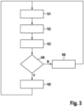
- Fig. 3 shows a flowchart for carrying out the procedural steps for setting the cruise control function. The flowchart is based on the activation of the cruise control function in the ego vehicle and the setting of a target speed in the cruise control function.
- a threshold value a is determined, which is as Function of the side distance x 1 is determined. It is advisable to set the threshold value a to a value greater than the side distance x 1 , but limited to a maximum value, which is in particular half the lane width. If necessary, other variables can be taken into account when determining the threshold value a, for example the type of road such as motorway, country road or local road.
- step V3 the current lateral distance x 2 between the ego vehicle and the motorcycle immediately in front is determined.
- step V4 the query is then made as to whether the lateral distance x 2 between the ego vehicle and the motorcycle immediately in front is less than or equal to the threshold value a. If this is the case, the yes branch ("Y") is followed by the next method step V5, according to which there is a group ride of the motorcycles and the ego vehicle follows the motorcycle immediately in front.
- control unit which can be part of an adaptive cruise control device in the single-track vehicle.
- This also includes a distance detection unit for detecting the longitudinal distance to a vehicle in front and for detecting the lateral distance between two single-track vehicles. After evaluating all the information, the control unit can be used to generate control signals for adjusting the drive motor and, if necessary, the brake system.
Landscapes
- Engineering & Computer Science (AREA)
- Automation & Control Theory (AREA)
- Transportation (AREA)
- Mechanical Engineering (AREA)
- Physics & Mathematics (AREA)
- Mathematical Physics (AREA)
- Control Of Driving Devices And Active Controlling Of Vehicle (AREA)
Abstract
Description
- Die Erfindung bezieht sich auf ein Verfahren zur Einstellung einer Tempomatfunktion mit automatischer Abstandseinstellung in einem Einspurfahrzeug.
- Bekannt sind Abstandstempomatfunktionen, mit deren Hilfe die aktuelle Fahrzeuggeschwindigkeit selbsttätig in Abhängigkeit des Abstandes zu einem vorausfahrenden Fahrzeug eingestellt wird. Hierbei kann der Fahrer eine Zielgeschwindigkeit im Abstandsregeltempomat einstellen, wobei die tatsächliche Fahrzeuggeschwindigkeit geringer sein kann und sich an der Geschwindigkeit des vorausfahrenden Fahrzeugs orientiert. Die Erfassung der Distanz zum vorausfahrenden Fahrzeug erfolgt üblicherweise mithilfe einer Radareinrichtung im Fahrzeug.
- Das erfindungsgemäße Verfahren bezieht sich auf die Einstellung einer Tempomatfunktion mit automatischer Abstandseinstellung in einem Einspurfahrzeug. Bei dem Einspurfahrzeug handelt es sich insbesondere um ein motorgetriebenes Einspurfahrzeug, vorzugsweise um motorgetriebenes Zweirad wie ein Motorrad oder ein Motorroller. Bei aktivierter Tempomatfunktion wird die Geschwindigkeit des Einspurfahrzeugs selbsttätig auf eine Zielgeschwindigkeit eingestellt, wobei sowohl Beschleunigungsvorgänge als auch Bremsvorgänge selbsttätig durchgeführt werden. Aufgrund der Ausführung als Tempomatfunktion mit automatischer Abstandseinstellung kann die tatsächliche Geschwindigkeit in Abhängigkeit eines vorausfahrenden Fahrzeuges eingestellt werden, das mithilfe einer Abstandserkennungseinheit detektiert wird. Die tatsächliche Geschwindigkeit kann auf die Geschwindigkeit des vorausfahrenden Fahrzeuges angepasst werden, wobei das folgende Fahrzeug einen geschwindigkeitsabhängigen Abstand zum vorausfahrenden Fahrzeug einhält.
- Das erfindungsgemäße Verfahren kann bei einer Gruppenfahrt von Einspurfahrzeugen eingesetzt werden. Bei aktivierter Tempomatfunktion mit vorgegebener Zielgeschwindigkeit wird zunächst mithilfe der Abstandserkennungseinheit der Seitenabstand zwischen zwei vorausfahrenden Einspurfahrzeugen ermittelt. Der Seitenabstand kennzeichnet die laterale Distanz quer zur Längsrichtung zwischen den beiden vorausfahrenden Einspurfahrzeugen.
- In einem folgenden Verfahrensschritt wird ein Schwellenwert ermittelt, der sich als Funktion des zuvor bestimmten Seitenabstandes zwischen den zwei vorausfahrenden Einspurfahrzeugen berechnet. Danach wird der Seitenabstand zwischen dem eigenen Einspurfahrzeug (im Folgenden: Ego-Fahrzeug) und einem vorausfahrenden Einspurfahrzeug, insbesondere dem unmittelbar vorausfahrenden Einspurfahrzeug ermittelt.
- Schließlich wird, in einem weiteren Verfahrensschritt, das, insbesondere unmittelbar, vorausfahrende Einspurfahrzeug als zu folgendem Zielfahrzeug für die Tempomatfunktion für den Fall verwendet, dass der Seitenabstand zwischen dem Ego-Fahrzeug und dem, insbesondere unmittelbar, vorausfahrenden Einspurfahrzeug kleiner oder gleich dem Schwellenwert ist.
- Diese Vorgehensweise hat den Vorteil, dass selbsttätig von der Tempomatfunktion entschieden wird, ob es sich um eine Gruppenfahrt handelt und das Ego-Fahrzeug als Teil der Gruppe einem vorausfahrenden Einspurfahrzeug folgt. Die Entscheidung kann mit einer bereits bestehenden Hardware einer Tempomatfunktion mit automatischer Abstandseinstellung getroffen werden; es ist keine zusätzliche Hardware erforderlich. Sofern selbsttätig erkannt wird, dass es sich um eine Gruppenfahrt handelt, zu der auch das Ego-Fahrzeug gehört, folgt das Ego-Fahrzeug einem vorausfahrenden Einspurfahrzeug, das Teil der Gruppe ist. Ergibt dagegen die Auswertung, dass die genannten Bedingungen für eine Teilnahme des Ego-Fahrzeugs an der Gruppenfahrt nicht vorliegen, was bei Überschreitung des Schwellenwerts der Fall ist, so wird die Geschwindigkeit im Ego-Fahrzeug auch nicht auf die Geschwindigkeit des vorausfahrenden Einspurfahrzeugs angepasst. In diesem Fall wird insbesondere im Fall einer höheren Zielgeschwindigkeit im Vergleich zur Geschwindigkeit der vorausfahrenden Einspurfahrzeuge ein Überholvorgang des Ego-Fahrzeugs bis zum Erreichen der Zielgeschwindigkeit durchgeführt.
- Die Ermittlung des Seitenabstandes sowohl zwischen den zwei vorausfahrenden Einspurfahrzeugen als auch zwischen dem Ego-Fahrzeug und einem vorausfahrenden Einspurfahrzeug kann mithilfe einer Abstandserkennungseinheit durchgeführt werden, die Bestandteil einer Abstandstempomateinrichtung zur Durchführung des Verfahrens ist. Bei der Abstandserkennungseinheit handelt es sich insbesondere um eine radarbasierte Abstandserkennungseinheit, mit deren Hilfe sowohl der Längsabstand zwischen dem Ego-Fahrzeug und einem oder mehreren vorausfahrenden Fahrzeugen als auch der Seitenabstand zwischen zwei vorausfahrenden Fahrzeugen und zwischen dem Ego-Fahrzeug und einem vorausfahrenden Fahrzeug ermittelt werden kann. Die Auflösung der radarbasierten Abstandserkennungseinheit ist sowohl für die Ermittlung des Längsabstandes als auch des Querabstandes gut genug.
- Das erfindungsgemäße Verfahren ist auf Situationen anwendbar, in denen mindestens zwei Einspurfahrzeuge vor dem Ego-Fahrzeug fahren. Es können gegebenenfalls mehr als zwei Einspurfahrzeuge sich vor dem Ego-Fahrzeug befinden. Mithilfe der Sensorik im Ego-Fahrzeug, die zu der Abstandserkennungseinheit gehört, wird insbesondere der Seitenabstand zwischen zwei unmittelbar vorausfahrenden Einspurfahrzeugen sowie zwischen dem Ego-Fahrzeug und dem nächsten vorausfahrenden Einspurfahrzeug ermittelt.
- Gemäß einer vorteilhaften Ausführung wird der Schwellenwert, der dem Vergleich mit dem Seitenabstand zwischen dem Ego-Fahrzeug und dem vorausfahrenden Einspurfahrzeug zugrunde gelegt wird, auf einen größeren Wert als der Seitenabstand zwischen den zwei vorausfahrenden Einspurfahrzeugen gesetzt. Der Schwellenwert ist beispielsweise um mindestens 10 %, um mindestens 20 %, um mindestens 30 %, um mindestens 40 % oder um mindestens 50 % größer als der Seitenabstand zwischen den zwei vorausfahrenden Einspurfahrzeugen. Indem der Schwellenwert auf einen größeren Wert als der Seitenabstand gesetzt wird, besteht eine ausreichend große Toleranz für das Ego-Fahrzeug zum Beitreten zur Gruppenfahrt und Anhängen an das vorausfahrende Einspurfahrzeug.
- Gemäß noch einer weiteren vorteilhaften Ausführung wird der Schwellenwert auf einen Maximalwert begrenzt. Dies stellt sicher, dass das Ego-Fahrzeug nur dann zur Gruppenfahrt gehörend erkannt wird, falls dieses sich innerhalb einer begrenzten seitlichen Distanz befindet. Es kann zwischen einer Gruppenfahrt und einem Überholvorgang unterschieden werden. Der Maximalwert wird beispielsweise auf die Fahrbahnbreite bzw. Fahrspurbreite der Straße gesetzt, auf der sich die vorausfahrenden Einspurfahrzeuge aktuell bewegen.
- Gemäß noch einer weiteren vorteilhaften Ausführung werden die Verfahrensschritte in regelmäßigen Zeitabständen durchgeführt, so dass entsprechend regelmäßig der Schwellenwert angepasst und die Abfrage durchgeführt wird, ob das Ego-Fahrzeug dem vorausfahrenden Einspurfahrzeug folgen soll. Mit dieser Abfrage können zum einen Situationen erfasst werden, in denen sich die Gruppenfahrt auflöst, beispielsweise durch Ausscheren eines oder mehrerer vorausfahrender Einspurfahrzeuge. Möglich ist auch das Erkennen sonstiger sich ändernder Bedingungen, beispielsweise das Überschreiten des Schwellenwertes durch einen sich vergrößernden Seitenabstand zwischen dem Ego-Fahrzeug und dem vorausfahrenden Einspurfahrzeug.
- Gemäß noch einer weiteren vorteilhaften Ausführung kann der Schwellenwert zusätzlich in Abhängigkeit weiterer Parameter oder Systemgrößen bestimmt werden, insbesondere in Abhängigkeit eines Straßenkennwerts wie beispielsweise dem Straßentyp oder Straßenbreite. So kann beispielsweise bei Fahrten auf Autobahnen der Schwellenwert auf einen höheren Maximalwert begrenzt werden als bei Fahrten auf kleineren Straßen, insbesondere in der Stadt. Die Erkennung des Straßentyps kann beispielsweise mithilfe eines Navigationssystems durchgeführt werden oder anhand eines Verkehrszeichenerkennungssystems. Die aktuelle Straßenbreite ergibt sich zum einen aus dem Straßentyp, zum andern kann ungeachtet der Erkennung des Straßentyps auch über eine Sensorik im Ego-Fahrzeug die Straßenbreite erkannt werden.
- Die Verfahrensschritte laufen in einem Steuergerät ab, das Teil einer Abstandstempomateinrichtung im Ego-Fahrzeug oder unabhängig von der Abstandstempomateinrichtung im Ego-Fahrzeug verbaut ist. Mithilfe des Steuergeräts können insbesondere Sensorinformationen der Abstandserkennungseinheit ausgewertet werden und die Geschwindigkeit des Ego-Fahrzeugs selbsttätig eingestellt werden, indem der Antriebsmotor und gegebenenfalls ein Bremssystem im Ego-Fahrzeug angesteuert werden.
- Die Erfindung bezieht sich außerdem auf eine Abstandstempomateinrichtung in einem Einspurfahrzeug mit einem vorbeschriebenen Steuergerät, einer Einrichtung zur selbsttätigen Geschwindigkeitseinstellung und einer Abstandserkennungseinheit zur Erkennung des Längsabstands zu einem vorausfahrenden Einspurfahrzeug und zur Erkennung des Seitenabstands zwischen zwei Einspurfahrzeugen, die beide vor dem Ego-Fahrzeug fahren oder des Seitenabstands zwischen dem Ego-Fahrzeug und einem vorausfahrenden Fahrzeug. Die Einrichtung zur selbsttätigen Geschwindigkeitseinstellung kann von dem Steuergerät selbst gebildet sein, in welchem Stellsignale zur Beaufschlagung des Antriebsmotors und des Bremssystems erzeugt werden.
- Die Erfindung bezieht sich schließlich auf ein Einspurfahrzeug wie beispielsweise ein Motorrad oder ein Motorroller, das mit einer vorbeschriebenen Abstandstempomateinrichtung ausgestattet ist.
- Die Erfindung bezieht sich außerdem auf ein Computerprogrammprodukt mit einem Programmcode, der dazu ausgelegt ist, die vorbeschriebenen Verfahrensschritte auszuführen. Das Computerprogrammprodukt läuft in einem vorbeschriebenen Steuergerät ab.
- Weitere Vorteile und zweckmäßige Ausführungen sind den weiteren Ansprüchen, der Figurenbeschreibung und den Zeichnungen zu entnehmen. Es zeigen:
- Fig. 1a
- eine Draufsicht auf drei Motorräder, die sich alle in Gruppenfahrt befinden,
- Fig. 1b
- eine Draufsicht auf die drei Motorräder, wobei das dritte, nachfolgende Motorrad zum Überholen ansetzt,
- Fig 2a, 2b
- weitere Draufsichten wie in
Fig. 1a, 1b , jedoch mit einem größeren seitlichen Abstand zwischen den beiden vorausfahrenden Motorrädern, - Fig. 3
- ein Ablaufdiagramm mit Verfahrensschritten zur Einstellung einer Tempomatfunktion mit automatischer Abstandseinstellung in einem Einspurfahrzeug.
- In den Figuren sind gleiche Bauteile mit gleichen Bezugszeichen versehen.
- In
Fig. 1a ist eine Draufsicht auf eine Gruppe von Einspurfahrzeugen dargestellt, die als Motorräder ausgeführt sind und auf einer Fahrspur einer Straße 1 entlangfahren. Die beiden vorausfahrenden Motorräder 2 und 3 fahren versetzt hintereinander und weisen zueinander einen Seitenabstand x1 auf, bezogen auf die Längserstreckung der Straße 1 und die Fahrtrichtung der Motorräder. Das nachfolgende Motorrad 4 ist mit einer Tempomatfunktion mit automatischer Abstandseinstellung ausgestattet, die es erlaubt, gegebenenfalls einem der vorausfahrenden Motorräder 2, 3 zu folgen, insbesondere dem unmittelbar vorausfahrenden Motorrad 3. Hierbei wird der Längsabstand zwischen dem vorausfahrenden Motorrad 3 und dem nachfolgenden Einspurfahrzeug 4 (Ego-Fahrzeug) mithilfe einer Abstandserkennungseinheit ermittelt, die insbesondere ein Radarsystem umfasst. Die Abstandserkennungseinheit erlaubt es auch, sowohl den Seitenabstand x1 zwischen den beiden vorausfahrenden Motorrädern 2 und 3 als auch den Seitenabstand x2 zwischen dem unmittelbar vorausfahrenden Fahrzeug 3 und dem Ego-Fahrzeug 4 zu ermitteln. Bei aktivierter Tempomatfunktion mit vorgegebener Zielgeschwindigkeit, welche höher ist als die Geschwindigkeit der vorausfahrenden Motorräder 2, 3, kann das Ego-Fahrzeug 4 je nach Seitenabstand x2 entweder einen Überholvorgang durchführen oder eine Gruppenfahrt mit den vorausfahrenden Motorrädern 2, 3 durchführen. - Die Erkennung, ob die beiden vorausfahrenden Motorräder 2, 3 gemeinsam mit dem Ego-Fahrzeug 4 eine zusammengehörende Gruppe, in der sich das Ego-Fahrzeug 4 bewegt, wird über einen Vergleich des aktuellen Seitenabstandes x2 zwischen dem Ego-Fahrzeug 4 und dem unmittelbar vorausfahrenden Motorrad 3 mit einem Schwellenwert a getroffen, der als Funktion des Seitenabstandes x1 zwischen den beiden vorausfahrenden Motorrädern 2, 3 bestimmt wird. Hierbei ist es zweckmäßig, dass der Schwellenwert a größer ist als der Seitenabstand x1 zwischen den Motorrädern 2, 3. Der Schwellenwert a kann beispielsweise um die Hälfte größer sein als der Seitenabstand x1, jedoch begrenzt auf einen Maximalwert, beispielsweise auf die Fahrbahnbreite bzw. Fahrspur, auf der sich die Motorräder 2, 3, 4 auf der Straße 1 bewegen.
- In
Fig. 1a ist eine Fahrsituation dargestellt, in der der Seitenabstand x2 zwischen dem Ego-Fahrzeug 4 und dem unmittelbar vorausfahrenden Motorrad 3 kleiner ist als der zuvor bestimmte Schwellenwert a, der als Funktion des Seitenabstandes x1 zwischen den beiden vorausfahrenden Motorrädern 2, 3 bestimmt wird. In diesem Fall wird von einer Gruppenfahrt ausgegangen, woraufhin die Tempomatfunktion mit automatischer Abstandseinstellung in der Weise durchgeführt wird, dass das Ego-Fahrzeug 4 sich an das unmittelbar vorausfahrende Motorrad 3 als Zielfahrzeug anhängt und diesem folgt. Dementsprechend wird über die Tempomatfunktion die Geschwindigkeit des Ego-Fahrzeugs 4 durch Ansteuerung des Antriebsmotors im Ego-Fahrzeug 4 und gegebenenfalls des Bremssystems eingestellt. - In
Fig. 1b ist eine Ausführungsvariante mit gleicher Ausgangssituation der vorausfahrenden Motorräder 2 und 3 dargestellt, die zueinander den Seitenstand x1 aufweisen, aus dem der Schwellenwert a ermittelt wird. Im Unterschied zuFig. 1a ist aber beiFig. 1b der Seitenabstand x2 zwischen dem Ego-Fahrzeug 4 und dem unmittelbar vorausfahrenden Motorrad 3 größer als der Schwellenwert a. In diesem Fall wird nicht von einer Gruppenfahrt ausgegangen, sondern von einem Überholvorgang, den das Ego-Fahrzeug 4 durchführt. Dementsprechend wird die aktuelle Geschwindigkeit des Ego-Fahrzeugs 4 nicht an die Geschwindigkeit des vorausfahrenden Motorrads3 angepasst, sondern das Ego-Fahrzeug 4 wird auf die eingestellte Zielgeschwindigkeit beschleunigt, die höher liegt als die Geschwindigkeit des vorausfahrenden Motorrads 3. - In
Fig. 2a ist eine Fahrsituation mit drei Motorrädern 2, 3, 4 auf einer Straße dargestellt, die grundsätzlich mit der Fahrsituation gemäßFig. 1a vergleichbar ist. Allerdings ist beiFig. 2a der Seitenabstand x1 zwischen den beiden vorausfahrenden Motorrädern 2, 3 größer, auch der Seitenabstand x2 zwischen dem Ego-Fahrzeug 4 und dem unmittelbar vorausfahrenden Motorrad 3 ist größer. Aus dem Seitenabstand x1 wird der Schwellenwert a berechnet, der etwa der Fahrbahnbreite entspricht. Da der Schwellenwert a größer ist als der Seitenabstand x2 zwischen dem Ego-Fahrzeug 4 und dem unmittelbar vorausfahrenden Motorrad 3, wird von einer Gruppenfahrt ausgegangen und die Geschwindigkeit des Fahrzeugs 4 an die Geschwindigkeit des unmittelbar vorausfahrenden Motorrads 3 angepasst. - In
Fig. 2b , in der die beiden vorausfahrenden Motorräder 2, 3 den gleichen Abstands x1 wie inFig. 2a aufweisen, ist der Seitenabstand x2 des Ego-Fahrzeugs 4 zum unmittelbar vorausfahrenden Motorrad 3 größer als der Schwellenwert a, so dass nicht von einer Gruppenfahrt ausgegangen wird und sich das Ego-Fahrzeug 4 nicht an das vorausfahrende Motorrad 3 anhängt. Vielmehr wird von einem Überholvorgang ausgegangen, bei dem das Ego-Fahrzeug 4 auf die eingestellte Zielgeschwindigkeit beschleunigt. -
Fig. 3 zeigt ein Ablaufdiagramm zur Durchführung der Verfahrensschritte für die Einstellung der Tempomatfunktion. Dem Ablaufdiagramm liegt die Aktivierung der Tempomatfunktion im Ego-Fahrzeug zugrunde und die Einstellung einer Zielgeschwindigkeit in der Tempomatfunktion. - Zunächst wird in einem ersten Verfahrensschritt V1 der Seitenabstand x1 zwischen zwei vorausfahrenden Motorrädern bestimmt. Anschließend erfolgt im nächsten Verfahrensschritt V2 die Ermittlung eines Schwellenwertes a, der als Funktion des Seitenabstandes x1 bestimmt wird. Hierbei ist es zweckmäßig, den Schwellenwert a auf einen größeren Wert als den Seitenabstand x1 zu setzen, jedoch begrenzt auf einen Maximalwert, der insbesondere bei der halben Fahrspurbreite liegt. Gegebenenfalls können bei der Bestimmung des Schwellenwerts a weitere Größen berücksichtigt werden, zum Beispiel der Straßentyp wie Autobahn, Landstraße oder Ortsstraße.
- Im folgenden Verfahrensschritt V3 wird der aktuelle Seitenabstand x2 zwischen dem Ego-Fahrzeug und dem unmittelbar vorausfahrenden Motorrad bestimmt. Im Verfahrensschritt V4 erfolgt anschließend die Abfrage, ob der Seitenabstand x2 zwischen dem Ego-Fahrzeug und dem unmittelbar vorausfahrenden Motorrad kleiner oder gleich dem Schwellenwert a ist. Ist dies der Fall, wird der Ja-Verzweigung ("Y") folgend zum nächsten Verfahrensschritt V5 vorgerückt, gemäß dem eine Gruppenfahrt der Motorräder vorliegt und das Ego-Fahrzeug dem unmittelbar vorausfahrenden Motorrad folgt.
- Ergibt dagegen die Abfrage im Verfahrensschritt V4, dass der Seitenabstand x2 größer ist als der Schwellenwert a, so kann nicht von einer Gruppenfahrt ausgegangen werden. In diesem Fall wird der Nein-Verzweigung ("N") folgend zum Verfahrensschritt V6 vorgerückt, gemäß dem von einem Überholvorgang des Ego-Fahrzeugs ausgegangen wird und die in der Tempomatfunktion eingestellte Zielgeschwindigkeit im Ego-Fahrzeug erreicht wird.
- Sowohl im Anschluss an den Verfahrensschritt V5 als auch im Anschluss an den Verfahrensschritt V6 wird wieder zum Verfahrensschritt V1 zurückgekehrt und das gesamte Verfahren in zyklischen Abständen erneut durchlaufen.
- Die verschiedenen Verfahrensschritte laufen in einem Steuergerät ab, das Teil einer Abstandstempomateinrichtung im Einspurfahrzeug sein kann. Diese umfasst außerdem eine Abstandserkennungseinheit zur Erkennung des Längsabstandes zu einem vorausfahrenden Fahrzeug und zur Erkennung des Seitenabstands zwischen zwei Einspurfahrzeugen. Über das Steuergerät können nach Auswertung aller Informationen Stellsignale zur Einstellung des Antriebsmotors und gegebenenfalls des Bremssystems erzeugt werden.
Claims (10)
- Verfahren zur Einstellung einer Tempomatfunktion mit automatischer Abstandseinstellung in einem Einspurfahrzeug (2, 39, mit folgenden Verfahrensschritten:a) Ermitteln des Seitenabstandes (x1) zwischen zwei vorausfahrenden Einspurfahrzeugen (2, 3),b) Bestimmen eines Schwellenwerts (a) als Funktion des Seitenabstandes (x1) zwischen den zwei vorausfahrenden Einspurfahrzeugen (2, 3),c) Ermitteln des Seitenabstandes (x2) zwischen dem eigenen Einspurfahrzeug (4) und einem vorausfahrenden Einspurfahrzeug (3),d) Verwenden des vorausfahrenden Einspurfahrzeugs (3) als zu folgendem Zielfahrzeug für die Tempomatfunktion für den Fall, dass der Seitenabstand (x2) zwischen dem eigenen Einspurfahrzeug (4) und dem vorausfahrenden Einspurfahrzeug (3) kleiner oder gleich dem Schwellenwert (a) ist.
- Verfahren nach Anspruch 1, dadurch gekennzeichnet, dass der Schwellenwert (a) auf einen größeren Wert als der Seitenabstand (x1) zwischen den zwei vorausfahrenden Einspurfahrzeugen (2, 3) gesetzt wird.
- Verfahren nach Anspruch 1 oder 2, dadurch gekennzeichnet, dass der Schwellenwert (a) auf einen Maximalwert begrenzt wird, beispielsweise auf die Fahrbahnbreite der Straße (1), auf der sich die Einspurfahrzeuge (2, 3, 4) aktuell bewegen.
- Verfahren nach einem der Ansprüche 1 bis 3, gekennzeichnet durch eine regelmäßige Durchführung der Verfahrensschritte mit einer Ermittlung und gegebenenfalls Anpassung des Schwellenwerts (a), des Seitenabstandes (x2) zwischen dem eigenen Einspurfahrzeug (4) und einem vorausfahrenden Einspurfahrzeug (3) und des Seitenabstandes (x1) zwischen zwei vorausfahrenden Einspurfahrzeugen (2, 3).
- Verfahren nach einem der Ansprüche 1 bis 4, dadurch gekennzeichnet, dass in der Tempomatfunktion eine Zielgeschwindigkeit vorgegeben wird, auf die für den Fall beschleunigt wird, dass der Seitenabstand (x2) zwischen dem eigenen Einspurfahrzeug (4) und dem vorausfahrenden Einspurfahrzeug (3) größer als der Schwellenwert (a) ist.
- Verfahren nach einem der Ansprüche 1 bis 5, dadurch gekennzeichnet, dass der Schwellenwert (a) zusätzlich in Abhängigkeit eines Straßenkennwerts ermittelt wird, beispielsweise in Abhängigkeit des Straßentyps oder der Straßenbreite.
- Steuergerät zur Durchführung des Verfahrens nach einem der Ansprüche 1 bis 6.
- Abstandstempomateinrichtung in einem Einspurfahrzeug (2, 3, 4), mit einem Steuergerät nach Anspruch 7, mit einer Einrichtung zur selbsttäigen Geschwindigkeitseinstellung und mit einer Abstandserkennungseinheit zur Erkennung des Längsabstands zu einem vorausfahrenden Einspurfahrzeug (2, 3, 4) und zur Erkennung des Seitenabstands zwischen zwei Einspurfahrzeugen (2, 3).
- Einspurfahrzeug, insbesondere Motorrad, mit einer Abstandstempomateinrichtung nach Anspruch 8.
- Computerprogrammprodukt mit einem Programmcode, der dazu ausgelegt ist, Schritte des Verfahrens nach einem der Ansprüche 1 bis 6 auszuführen, wenn das Computerprogrammprodukt in einem Steuergerät gemäß Anspruch 7 abläuft.
Applications Claiming Priority (1)
| Application Number | Priority Date | Filing Date | Title |
|---|---|---|---|
| DE102022204994.2A DE102022204994A1 (de) | 2022-05-19 | 2022-05-19 | Verfahren zur Einstellung einer Tempomatfunktion mit automatischer Abstandseinstellung in einem Einspurfahrzeug |
Publications (2)
| Publication Number | Publication Date |
|---|---|
| EP4279351A1 true EP4279351A1 (de) | 2023-11-22 |
| EP4279351B1 EP4279351B1 (de) | 2025-06-04 |
Family
ID=85415366
Family Applications (1)
| Application Number | Title | Priority Date | Filing Date |
|---|---|---|---|
| EP23159636.2A Active EP4279351B1 (de) | 2022-05-19 | 2023-03-02 | Verfahren zur einstellung einer tempomatfunktion mit automatischer abstandseinstellung in einem einspurfahrzeug |
Country Status (3)
| Country | Link |
|---|---|
| US (1) | US12466407B2 (de) |
| EP (1) | EP4279351B1 (de) |
| DE (1) | DE102022204994A1 (de) |
Families Citing this family (1)
| Publication number | Priority date | Publication date | Assignee | Title |
|---|---|---|---|---|
| EP4446187A1 (de) * | 2021-12-07 | 2024-10-16 | Robert Bosch GmbH | Steuerungsvorrichtung und steuerungsverfahren für fahrerassistenzsystem |
Citations (3)
| Publication number | Priority date | Publication date | Assignee | Title |
|---|---|---|---|---|
| DE102019201141A1 (de) * | 2018-02-12 | 2019-08-14 | Harley-Davidson Motor Company Group, LLC | Adaptiver Geschwindigkeitsregler in einem Motorrad zur Zielverfolgung |
| DE102019200209A1 (de) * | 2019-01-10 | 2020-07-16 | Robert Bosch Gmbh | Verfahren und Vorrichtung zur Auswahl des Zielobjekts für eine automatische Abstandsregelung eines einspurigen Kraftfahrzeugs |
| DE102019205881A1 (de) * | 2019-04-25 | 2020-10-29 | Robert Bosch Gmbh | Verfahren und Vorrichtung zur automatischen Einstellung eines Geschwindigkeits- oder Abstandsregelungssystems eines einspurigen Kraftfahrzeugs |
Family Cites Families (6)
| Publication number | Priority date | Publication date | Assignee | Title |
|---|---|---|---|---|
| JP6410509B2 (ja) | 2014-08-04 | 2018-10-24 | 株式会社エフ・シー・シー | 鞍乗り型車両 |
| EP3335954A4 (de) | 2015-08-17 | 2018-09-12 | Yamaha Hatsudoki Kabushiki Kaisha | Neigefahrzeug |
| DE102016224913A1 (de) * | 2016-12-14 | 2018-06-14 | Robert Bosch Gmbh | Verfahren zur selbsttätigen Einstellung der Geschwindigkeit eines Motorrads |
| WO2019235395A1 (ja) | 2018-06-04 | 2019-12-12 | ヤマハ発動機株式会社 | リーン車両 |
| WO2020041188A1 (en) | 2018-08-20 | 2020-02-27 | Indian Motorcycle International, LLC | Wheeled vehicle adaptive speed control method and system |
| JP7755552B2 (ja) * | 2022-07-01 | 2025-10-16 | 本田技研工業株式会社 | 運転支援システム |
-
2022
- 2022-05-19 DE DE102022204994.2A patent/DE102022204994A1/de active Pending
-
2023
- 2023-03-02 EP EP23159636.2A patent/EP4279351B1/de active Active
- 2023-03-27 US US18/190,694 patent/US12466407B2/en active Active
Patent Citations (3)
| Publication number | Priority date | Publication date | Assignee | Title |
|---|---|---|---|---|
| DE102019201141A1 (de) * | 2018-02-12 | 2019-08-14 | Harley-Davidson Motor Company Group, LLC | Adaptiver Geschwindigkeitsregler in einem Motorrad zur Zielverfolgung |
| DE102019200209A1 (de) * | 2019-01-10 | 2020-07-16 | Robert Bosch Gmbh | Verfahren und Vorrichtung zur Auswahl des Zielobjekts für eine automatische Abstandsregelung eines einspurigen Kraftfahrzeugs |
| DE102019205881A1 (de) * | 2019-04-25 | 2020-10-29 | Robert Bosch Gmbh | Verfahren und Vorrichtung zur automatischen Einstellung eines Geschwindigkeits- oder Abstandsregelungssystems eines einspurigen Kraftfahrzeugs |
Also Published As
| Publication number | Publication date |
|---|---|
| US12466407B2 (en) | 2025-11-11 |
| US20230373482A1 (en) | 2023-11-23 |
| DE102022204994A1 (de) | 2023-11-23 |
| EP4279351B1 (de) | 2025-06-04 |
Similar Documents
| Publication | Publication Date | Title |
|---|---|---|
| EP1841615B1 (de) | Fahrerassistenzsystem mit fahrschlauchprädiktion | |
| EP1808350B1 (de) | Verfahren zum Betrieb eines Längsführungssystems in einem Kraftfahrzeug | |
| EP3160813B1 (de) | Verfahren zur erstellung eines umfeldmodells eines fahrzeugs | |
| DE69516934T2 (de) | Vorrichtung zur Fahrhilfe eines Fahrzeugs | |
| DE102014209585B4 (de) | Kollisionsminderungsvorrichtung | |
| DE102006030178A1 (de) | Verfahren und System zur Unterstützung des Fahrers eines Kraftfahrzeugs bei der Erkennung von Bodenschwellen | |
| WO2015082185A1 (de) | Verfahren zum durchführen eines zumindest semi-autonomen einparkvorgangs eines kraftfahrzeugs, parkassistenzsystem und kraftfahrzeug | |
| EP2251240A1 (de) | Verfahren zur automatischen Längsführung eines Kraftfahrzeugs umfassend ein adaptives Längsführungssystem (ACC-System) | |
| EP2676857A2 (de) | Verfahren und Vorrichtung zum Erzeugen eines Steuerparameters für ein Abstandsassistenzsystem eines Fahrzeugs | |
| DE102019217144B4 (de) | Ampelspurzuordnung aus Schwarmdaten | |
| EP1844373A1 (de) | Verfahren zur kursprädiktion in fahrerassistenzsystemen für kraftfahrzeuge | |
| DE102017209533A1 (de) | Spurwechselassistenzsystem und Spurwechselassistenzverfahren mit erhöhter Sicherheit für den Fahrer und andere Verkehrsteilnehmer | |
| DE102019217099A1 (de) | Steuerungssystem und Steuerungsverfahren für ein Erkennen und eine Reaktion eines Reißverschlussverfahrens für ein Kraftfahrzeug | |
| WO2016074819A1 (de) | Verfahren zum betreiben eines fahrerassistenzsystems und fahrerassistenzsystem | |
| DE112020005886T5 (de) | Fahrzeugsteuerungsvorrichtung | |
| EP2493746B1 (de) | Verfahren zur unterstützung eines fahrers beim einparken | |
| DE10321412A1 (de) | Vorrichtung zur Längsführung eines Kraftfahrzeugs | |
| EP4279351B1 (de) | Verfahren zur einstellung einer tempomatfunktion mit automatischer abstandseinstellung in einem einspurfahrzeug | |
| DE102005062086A1 (de) | Verfahren zum Ermitteln der Befahrbarkeit einer Parklücke und Einparkhilfeeinrichtung | |
| EP2628662A1 (de) | Verfahren für ein Assistenzsystem eines Fahrzeugs | |
| EP4126617B1 (de) | Verfahren zur steuerung eines zumindest teilweise autonom fahrenden eigenfahrzeuges | |
| DE19601831C5 (de) | Verfahren zur Erkennung von relevanten Objekten | |
| EP4364107A1 (de) | Verfahren und vorrichtung zum unterstützen einer umfelderkennung für ein automatisiert fahrendes fahrzeug | |
| EP1529719B1 (de) | Fahrzeugführungsvorrichtung mit Querführung und Objekterkennung sowie entsprechendes Verfahren | |
| DE102010056248A1 (de) | Verfahren und Abstandsregelsystem zur Regelung eines Folgeabstands |
Legal Events
| Date | Code | Title | Description |
|---|---|---|---|
| PUAI | Public reference made under article 153(3) epc to a published international application that has entered the european phase |
Free format text: ORIGINAL CODE: 0009012 |
|
| STAA | Information on the status of an ep patent application or granted ep patent |
Free format text: STATUS: THE APPLICATION HAS BEEN PUBLISHED |
|
| AK | Designated contracting states |
Kind code of ref document: A1 Designated state(s): AL AT BE BG CH CY CZ DE DK EE ES FI FR GB GR HR HU IE IS IT LI LT LU LV MC ME MK MT NL NO PL PT RO RS SE SI SK SM TR |
|
| STAA | Information on the status of an ep patent application or granted ep patent |
Free format text: STATUS: REQUEST FOR EXAMINATION WAS MADE |
|
| 17P | Request for examination filed |
Effective date: 20240522 |
|
| RBV | Designated contracting states (corrected) |
Designated state(s): AL AT BE BG CH CY CZ DE DK EE ES FI FR GB GR HR HU IE IS IT LI LT LU LV MC ME MK MT NL NO PL PT RO RS SE SI SK SM TR |
|
| GRAP | Despatch of communication of intention to grant a patent |
Free format text: ORIGINAL CODE: EPIDOSNIGR1 |
|
| STAA | Information on the status of an ep patent application or granted ep patent |
Free format text: STATUS: GRANT OF PATENT IS INTENDED |
|
| INTG | Intention to grant announced |
Effective date: 20250102 |
|
| GRAS | Grant fee paid |
Free format text: ORIGINAL CODE: EPIDOSNIGR3 |
|
| GRAA | (expected) grant |
Free format text: ORIGINAL CODE: 0009210 |
|
| STAA | Information on the status of an ep patent application or granted ep patent |
Free format text: STATUS: THE PATENT HAS BEEN GRANTED |
|
| AK | Designated contracting states |
Kind code of ref document: B1 Designated state(s): AL AT BE BG CH CY CZ DE DK EE ES FI FR GB GR HR HU IE IS IT LI LT LU LV MC ME MK MT NL NO PL PT RO RS SE SI SK SM TR |
|
| REG | Reference to a national code |
Ref country code: GB Ref legal event code: FG4D Free format text: NOT ENGLISH |
|
| REG | Reference to a national code |
Ref country code: CH Ref legal event code: EP |
|
| REG | Reference to a national code |
Ref country code: DE Ref legal event code: R096 Ref document number: 502023001065 Country of ref document: DE |
|
| REG | Reference to a national code |
Ref country code: IE Ref legal event code: FG4D Free format text: LANGUAGE OF EP DOCUMENT: GERMAN |
|
| REG | Reference to a national code |
Ref country code: NL Ref legal event code: MP Effective date: 20250604 |
|
| PG25 | Lapsed in a contracting state [announced via postgrant information from national office to epo] |
Ref country code: ES Free format text: LAPSE BECAUSE OF FAILURE TO SUBMIT A TRANSLATION OF THE DESCRIPTION OR TO PAY THE FEE WITHIN THE PRESCRIBED TIME-LIMIT Effective date: 20250604 Ref country code: FI Free format text: LAPSE BECAUSE OF FAILURE TO SUBMIT A TRANSLATION OF THE DESCRIPTION OR TO PAY THE FEE WITHIN THE PRESCRIBED TIME-LIMIT Effective date: 20250604 |
|
| REG | Reference to a national code |
Ref country code: LT Ref legal event code: MG9D |
|
| PG25 | Lapsed in a contracting state [announced via postgrant information from national office to epo] |
Ref country code: GR Free format text: LAPSE BECAUSE OF FAILURE TO SUBMIT A TRANSLATION OF THE DESCRIPTION OR TO PAY THE FEE WITHIN THE PRESCRIBED TIME-LIMIT Effective date: 20250905 Ref country code: NO Free format text: LAPSE BECAUSE OF FAILURE TO SUBMIT A TRANSLATION OF THE DESCRIPTION OR TO PAY THE FEE WITHIN THE PRESCRIBED TIME-LIMIT Effective date: 20250904 |
|
| PG25 | Lapsed in a contracting state [announced via postgrant information from national office to epo] |
Ref country code: PL Free format text: LAPSE BECAUSE OF FAILURE TO SUBMIT A TRANSLATION OF THE DESCRIPTION OR TO PAY THE FEE WITHIN THE PRESCRIBED TIME-LIMIT Effective date: 20250604 |
|
| PG25 | Lapsed in a contracting state [announced via postgrant information from national office to epo] |
Ref country code: BG Free format text: LAPSE BECAUSE OF FAILURE TO SUBMIT A TRANSLATION OF THE DESCRIPTION OR TO PAY THE FEE WITHIN THE PRESCRIBED TIME-LIMIT Effective date: 20250604 |
|
| PG25 | Lapsed in a contracting state [announced via postgrant information from national office to epo] |
Ref country code: HR Free format text: LAPSE BECAUSE OF FAILURE TO SUBMIT A TRANSLATION OF THE DESCRIPTION OR TO PAY THE FEE WITHIN THE PRESCRIBED TIME-LIMIT Effective date: 20250604 |
|
| PG25 | Lapsed in a contracting state [announced via postgrant information from national office to epo] |
Ref country code: RS Free format text: LAPSE BECAUSE OF FAILURE TO SUBMIT A TRANSLATION OF THE DESCRIPTION OR TO PAY THE FEE WITHIN THE PRESCRIBED TIME-LIMIT Effective date: 20250904 |
|
| PG25 | Lapsed in a contracting state [announced via postgrant information from national office to epo] |
Ref country code: LV Free format text: LAPSE BECAUSE OF FAILURE TO SUBMIT A TRANSLATION OF THE DESCRIPTION OR TO PAY THE FEE WITHIN THE PRESCRIBED TIME-LIMIT Effective date: 20250604 |
|
| PG25 | Lapsed in a contracting state [announced via postgrant information from national office to epo] |
Ref country code: NL Free format text: LAPSE BECAUSE OF FAILURE TO SUBMIT A TRANSLATION OF THE DESCRIPTION OR TO PAY THE FEE WITHIN THE PRESCRIBED TIME-LIMIT Effective date: 20250604 |
|
| PG25 | Lapsed in a contracting state [announced via postgrant information from national office to epo] |
Ref country code: PT Free format text: LAPSE BECAUSE OF FAILURE TO SUBMIT A TRANSLATION OF THE DESCRIPTION OR TO PAY THE FEE WITHIN THE PRESCRIBED TIME-LIMIT Effective date: 20251006 |
|
| PG25 | Lapsed in a contracting state [announced via postgrant information from national office to epo] |
Ref country code: IS Free format text: LAPSE BECAUSE OF FAILURE TO SUBMIT A TRANSLATION OF THE DESCRIPTION OR TO PAY THE FEE WITHIN THE PRESCRIBED TIME-LIMIT Effective date: 20251004 |
|
| PG25 | Lapsed in a contracting state [announced via postgrant information from national office to epo] |
Ref country code: SM Free format text: LAPSE BECAUSE OF FAILURE TO SUBMIT A TRANSLATION OF THE DESCRIPTION OR TO PAY THE FEE WITHIN THE PRESCRIBED TIME-LIMIT Effective date: 20250604 |
|
| PG25 | Lapsed in a contracting state [announced via postgrant information from national office to epo] |
Ref country code: CZ Free format text: LAPSE BECAUSE OF FAILURE TO SUBMIT A TRANSLATION OF THE DESCRIPTION OR TO PAY THE FEE WITHIN THE PRESCRIBED TIME-LIMIT Effective date: 20250604 |
|
| PG25 | Lapsed in a contracting state [announced via postgrant information from national office to epo] |
Ref country code: EE Free format text: LAPSE BECAUSE OF FAILURE TO SUBMIT A TRANSLATION OF THE DESCRIPTION OR TO PAY THE FEE WITHIN THE PRESCRIBED TIME-LIMIT Effective date: 20250604 |
|
| PG25 | Lapsed in a contracting state [announced via postgrant information from national office to epo] |
Ref country code: SK Free format text: LAPSE BECAUSE OF FAILURE TO SUBMIT A TRANSLATION OF THE DESCRIPTION OR TO PAY THE FEE WITHIN THE PRESCRIBED TIME-LIMIT Effective date: 20250604 |
|
| PG25 | Lapsed in a contracting state [announced via postgrant information from national office to epo] |
Ref country code: IT Free format text: LAPSE BECAUSE OF FAILURE TO SUBMIT A TRANSLATION OF THE DESCRIPTION OR TO PAY THE FEE WITHIN THE PRESCRIBED TIME-LIMIT Effective date: 20250604 |
|
| REG | Reference to a national code |
Ref country code: DE Ref legal event code: R097 Ref document number: 502023001065 Country of ref document: DE |
|
| PLBE | No opposition filed within time limit |
Free format text: ORIGINAL CODE: 0009261 |
|
| STAA | Information on the status of an ep patent application or granted ep patent |
Free format text: STATUS: NO OPPOSITION FILED WITHIN TIME LIMIT |
|
| PG25 | Lapsed in a contracting state [announced via postgrant information from national office to epo] |
Ref country code: DK Free format text: LAPSE BECAUSE OF FAILURE TO SUBMIT A TRANSLATION OF THE DESCRIPTION OR TO PAY THE FEE WITHIN THE PRESCRIBED TIME-LIMIT Effective date: 20250604 |
|
| PGFP | Annual fee paid to national office [announced via postgrant information from national office to epo] |
Ref country code: AT Payment date: 20260301 Year of fee payment: 4 |
|
| REG | Reference to a national code |
Ref country code: CH Ref legal event code: L10 Free format text: ST27 STATUS EVENT CODE: U-0-0-L10-L00 (AS PROVIDED BY THE NATIONAL OFFICE) Effective date: 20260416 |