EP4278908B1 - Überdruckventil für eine wasserpfeife - Google Patents
Überdruckventil für eine wasserpfeife Download PDFInfo
- Publication number
- EP4278908B1 EP4278908B1 EP23173638.0A EP23173638A EP4278908B1 EP 4278908 B1 EP4278908 B1 EP 4278908B1 EP 23173638 A EP23173638 A EP 23173638A EP 4278908 B1 EP4278908 B1 EP 4278908B1
- Authority
- EP
- European Patent Office
- Prior art keywords
- hookah
- sealing element
- bore
- gasket
- valve
- Prior art date
- Legal status (The legal status is an assumption and is not a legal conclusion. Google has not performed a legal analysis and makes no representation as to the accuracy of the status listed.)
- Active
Links
Images
Classifications
-
- A—HUMAN NECESSITIES
- A24—TOBACCO; CIGARS; CIGARETTES; SIMULATED SMOKING DEVICES; SMOKERS' REQUISITES
- A24F—SMOKERS' REQUISITES; MATCH BOXES; SIMULATED SMOKING DEVICES
- A24F1/00—Tobacco pipes
- A24F1/30—Hookahs
-
- F—MECHANICAL ENGINEERING; LIGHTING; HEATING; WEAPONS; BLASTING
- F16—ENGINEERING ELEMENTS AND UNITS; GENERAL MEASURES FOR PRODUCING AND MAINTAINING EFFECTIVE FUNCTIONING OF MACHINES OR INSTALLATIONS; THERMAL INSULATION IN GENERAL
- F16K—VALVES; TAPS; COCKS; ACTUATING-FLOATS; DEVICES FOR VENTING OR AERATING
- F16K15/00—Check valves
- F16K15/02—Check valves with guided rigid valve members
- F16K15/08—Check valves with guided rigid valve members shaped as rings
Definitions
- the invention falls within the field of hookahs used for inhaling tobacco smoke or tobacco substitutes, and relates to a structural part of the hookah referred to by the skilled art as a valve.
- Hookahs have been a familiar construct used for smoke inhalation for several centuries. Hookahs provide the user with smoke that overcomes the water column, whereby the originally hot smoke is cooled and, according to some sources, purified before being drawn into the mouth.
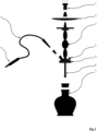
- the vast majority of hookahs are constructed from the following structural components, with their relative arrangement schematically illustrated in Figure 1 .
- the first structural component is the bowl, which is used to house the tobacco and the ember.
- an ash tray below the bowl is an ash tray (see relation mark 2 in Figure 1 ) which serves as a collector for any fallen parts of the hot embers that might be released from the bowl.
- the bowl is attached to a body (alternatively called the stem) that guides the hot smoke towards a gasket.
- the body may be fitted with decorative elements.
- the gasket acts as a junction for the flow of the smoke, as it conducts the smoke through the water to the hose when the smoke is drawn in, while when the hookah is puff through its valve lets the hot air and uninhaled smoke from the water jar into the surrounding environment.
- a downstem protrudes from the gasket to introduce the hot smoke below the level of the water poured into the water jar.
- Another structural component of the hookah is the water jar, which acts as a container for the water and at the same time acts as a stable base for the hookah.
- the water jar is enclosed by a gasket, with the only escape route for the cooled smoke being through the gasket to the hose.
- the hose serves as a conduit for the cooled smoke to the hookah user.
- the hose is terminated by a hose handle with a mouth tip (see relation mark 9 in Figure 1 ) which is inserted into the mouth of the user.
- a hose handle with a mouth tip (see relation mark 9 in Figure 1 ) which is inserted into the mouth of the user.
- various sealing grommets and means which are not essential for an informative listing of the main components of the hookah.
- the gasket is a structural part of the hookah that is indispensable for the proper functioning of the hookah. Not only does the gasket pressure seal the water jar, but it also allows the water jar space to be purged above the water being poured, thanks to the existence of valve, which is usually part of the gasket. On the other hand, there are hookahs where the valve is separate, either on the water jar or on the body, but these are mostly artistically designed hookahs.
- Hookah puffing is an activity in which the user does not puff from the hookah but instead blows into the hookah. Blowing cools the water jar area and at the same time cleans it of smoke residue.
- valves they are designed as ball valves.
- the construction of a hookah ball valve may be imagined as being a ball loosely placed in a hole with a tapered end connecting the inside of the water jar to the outside, which is seated by the earth's gravity at the bottom of the hole near the tapered end and touches the tapering walls of the hole, thus closing it.
- the vacuum inside the water jar exerts a pressure through the opening on the ball to draw it towards the tapering opening, thereby further sealing the opening.
- the overpressure acts on the ball by pushing it towards the wider part of the hole, whereupon the ball stops touching the walls of the hole and the overpressure from the water jar is allowed to escape around the ball of the valve through the hole into the surrounding environment of the hookah.
- the invention of DE 20 2020 104 097 U1 is known in which the problem of zero puffing of the crown of a hookah with tobacco is solved.
- air from the puffing of the hookah is allowed to travel into the crown of the hookah with tobacco.
- the disadvantage of this invention is that it still relies on ball valves, which have been described above as being unreliable for very intense puffing, which can allow water to enter the hookah crown.
- the object of the invention is to create a hookah which is capable of releasing the overpressure caused by user from the water jar when blowing without causing water to spill into the bowl, which is unbreakable due to its robust construction, but at the same time easy to fabricate, and which is easy to clean.
- the hookah valve is used to purge the hookah.
- the valve comprises at least one opening leading through the stem heart of the hookah to form a channel leading between the base of the hookah and the outer surroundings of the hookah. At the same time, the opening is sealed by a movable sealing means.
- the movable sealing means of the release valve comprises a sealing body provided with a hole for pull a body through the sealing element whereby the sealing element is longitudinally movable along the body.
- the inventive solution replaces existing ball solutions, whereby the size of the bore, or number of bores, is limited only by the dimensions of the gasket of the hookah.
- a large bore, or a group of small bores, can be covered by a single sealing element.
- the manufacture of the valve according to the invention is very simple, as the bores with the tapered end do not have to be complicated to make, but can simply be drilled through the gasket. Moreover, disassembly and maintenance of the valve is also very easy. The user only has to take care of one sealing element, which has much less tendency to become jammed than the balls in existing valves.
- the sealing element has the shape of a ring, a plate or a 3D structure with at least one surface for seating on bore leading through the gasket. Since hookahs are generally shaped like rotating bodies, it is preferable that the plate is also shaped like a rotating body, ideally a ring. On the other hand, the invention also works for very original shapes of hookahs, where the shape may be square or otherwise. Spatial structures will not be an exception, especially in artistically conceived hookahs, provided that the spatial structure will be seated to close the bores of gasket.
- Advantageous embodiments of the invention also include one in which the sealing element is provided with a guide flange.
- the guide flange helps to prevent the sealing element from jamming by crossing against the body during purging puffing.
- the guide flange ensures smooth up and down movement of the sealing element along the body.
- the bore is provided with a recess for a seal.
- the seal serves a dual function. Firstly, it seals the contact between the sealing element lying down and bore. Secondly, particularly if water enters the valve, it prevents the smooth surfaces wetted by water from sticking together on contact, since the seal does not allow the sealing element to fully seat on the gasket in the area of the bore leading through the gasket.
- the bore is groove.
- the groove has a larger cross-section through which air can escape during purging puffing.
- modern machine tools can just as easily produce a series of bores or a single groove.
- the total cross-sectional area of the bore is greater than the cross-sectional area of the hose handle. If this condition is met, it is impossible for the user to push water into the bowl when exhale puffing.
- the sealing element may be provided with a bearing or friction reducing means integrated into the hole for pulling the body of the hookah through.
- a bearing or friction reducing means integrated into the hole for pulling the body of the hookah through.
- the sealing element may be provided with a hydrophobic surface treatment. This treatment prevents water from bonding the moving and non-moving components together in the event of water splashing.
- the advantages of the invention include, in particular, the sizing of the overall cross-section of the bore forming the channel through the gasket, which can be achieved by the number of bores, the size of the diameter of the individual bores, or by joining the bores into a single groove, all sealed by a single sealing element.
- the production of the hookah according to the invention is easy, fast and cost effective, compared to the hookahs produced to date. Moreover, maintenance of the valve according to the invention is not difficult. When the body is disassembled from the gasket, the sealing element is stored and the bores passing through the gasket can be cleaned.
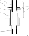
- the gasket 4 of the hookah exhibits a main channel through which the hot smoke passes from the body 3 to the downstem 6 .
- the gasket 4 in Figure 2 is shown as if it were inserted into the neck of the water jar 7 .
- the gasket 4 of the hookahs is made of duralumin, but an expert in the use of materials in the food industry will be able to suggest other materials suitable for use with the hot smoke that is inhaled after it passes through the water column.
- duralumin used it is inert, mechanically resistant, and easy to machine, compared to, for example, stainless steel, which is very difficult to machine.
- the bore 10 forms a channel of the inventive valve 5 for purging puffing the hookah.
- the bore 10 passes through the gasket 4, having an outlet at the upper base of the gasket 4 .
- the bore 10 appears as a single circular channel. This is certainly a possible embodiment, but variations have been successfully tested where the bore 10 have been a group within a release valve 5 , or the bore 10 has been enlarged into a groove, the number of grooves also being selectable.
- a sealing element 11 is deployed onto the body 1 to form the second part of the valve 5 .
- the sealing element 11 is also made of duralumin, but other materials may be considered.
- the sealing element 11 has the shape of an annulus which is perforated to allow the body 1 to pass through its hole 12.
- the depicted ring forming the sealing element 11 is provided with a guide flange 13 which lines the hole 12 in the ring, so that the guide flange 13 is adjacent to the body 3 . In this way, the sealing element 11 is prevented from tilting and possibly crossing on the body 3 .
- a deflection of the material is made on the gasket 4 , whereupon the guide flange 13 of the sealing element 11 can easily fit into the resulting space.
- a variety of shapes of the sealing element 11 are possible, depending also on the artistic concept of the hookah. Square plates, rectangular plates, spherical sections, 3D structures with a flat base for seating on the bore 10 were tested.
- the sealing element 11 is mounted on the body 1 with clearance so that it can slide along it.
- a stop is formed on the body 3 , but the stop is not a mandatory technical feature.
- the vacuum at the bore 10 pulls the sealing element 11 towards the gasket 4 .
- the overpressure lifts the sealing element 11 away from the gasket 4 . If neither of these activities is occurring, the sealing element 11 is lying on the upper base of the gasket 4 due to Earth gravity.
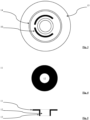
- Figure 3 shows the upper base of the gasket 4 as viewed from above.
- the recess 14 for the sealing can be seen in the figure.
- two bores 10 in the form of grooves are clearly visible.
- the last clearly visible part of the gasket 4 is the gasket surface 15 , on which decorative elements can be supported, which can also be simultaneously fixed on the body 3 of the hookah.
- FIGS 4 and 5 show a detail of the sealing element 11 .
- the sealing element 11 is annular in shape, but if the design of the hookah is different, the sealing element 11 can be adapted in shape. It is important that the sealing element 11 can slide freely along the body 3 and sit above bores 10 .
- the hookah according to the invention will find application in both newly manufactured and existing hookahs, where a simple replacement of the gasket and optionally the body of all structural components of the hookah is sufficient.
Landscapes
- Engineering & Computer Science (AREA)
- General Engineering & Computer Science (AREA)
- Mechanical Engineering (AREA)
- Check Valves (AREA)
- Self-Closing Valves And Venting Or Aerating Valves (AREA)
- Gasket Seals (AREA)
Claims (8)
- Wasserpfeife mit einem Ventil (5) zum Entleeren der Wasserpfeife durch Ausatmen, d.h. in ihr Wassergefäß (7) zu blasen, umfassend eine Schale (1) für Tabak, einen Körper (3), der mit einem Stiel (6) endet, um den Rauch aus der Schale (1) in das Wassergefäß (7) zu leiten, eine Dichtung (4) zum Abdichten des Wassergefäßes (7), wobei die Dichtung (4) mit einer Bohrung für den Körper (3) versehen ist, ferner mit mindestens einem Schlauch (8) versehen ist und ferner mit mindestens einer Bohrung (10) versehen ist, die sich durch eine Dichtung (4) erstreckt, um einen Kanal zu bilden, der zwischen dem Inneren des Wasserbehälters (7) und dem Äußeren der Wasserpfeife führt, wobei die Bohrung (10) durch das Ventil (5) abgedichtet ist, dadurch gekennzeichnet, dass das Ventil (5) ein Dichtungselement (11) umfasst, das mit einem Loch (12) zur Aufnahme des Körpers (3) durch das Dichtungselement (11) versehen ist, wobei das Dichtungselement (11) in Längsrichtung entlang des Körpers (3) beweglich ist, und die Bohrung (10) unter dem Dichtungselement (11) angeordnet ist, das darüber platziert ist, um die Bohrung (10) während des Einatmens aus dem Wassertank (7) abzudichten und um die Bohrung (10) während des Ausatmens in den Wassertank (7) zu öffnen, indem sie durch die Wirkung des Überdrucks im Wassertank (7) nach oben gleitet.
- Die Wasserpfeife nach Anspruch 1, dadurch gekennzeichnet, dass das Dichtungselement (11) die Form einer Platte, eines Rings oder einer 3D-Struktur mit mindestens einer Fläche zum Aufsetzen auf die Bohrung (10) hat.
- Die Wasserpfeife nach Anspruch 1 oder 2, dadurch gekennzeichnet, dass das Dichtelement (11) mit einem Führungsflansch (13) versehen ist.
- Die Wasserpfeife nach einem der Ansprüche 1 bis 3, dadurch gekennzeichnet, dass das Dichtungselement (11) mit einer hydrophoben Beschichtung versehen ist.
- Die Wasserpfeife nach einem der Ansprüche 1 bis 4, dadurch gekennzeichnet, dass die Bohrung (10) die Form einer durchgehenden Rille hat.
- Die Wasserpfeife nach einem der Ansprüche 1 bis 5, dadurch gekennzeichnet, dass die Gesamtquerschnittsfläche der Bohrung (10) größer ist als die Querschnittsfläche eines Schlauches (8) der Wasserpfeife.
- Die Wasserpfeife nach einem der Ansprüche 1 bis 6, dadurch gekennzeichnet, dass das Dichtungselement (11) mit einem in das Loch (12) integrierten Lager oder reibungsmindernden Mittel versehen ist.
- Die Wasserpfeife nach einem der Ansprüche 1 bis 7, dadurch gekennzeichnet, dass die Bohrung (10) mit einer Nut für ihre Abdichtung versehen ist.
Applications Claiming Priority (1)
| Application Number | Priority Date | Filing Date | Title |
|---|---|---|---|
| CZ2022-206A CZ309555B6 (cs) | 2022-05-18 | 2022-05-18 | Zpětný ventil pro vodní dýmku |
Publications (3)
| Publication Number | Publication Date |
|---|---|
| EP4278908A1 EP4278908A1 (de) | 2023-11-22 |
| EP4278908C0 EP4278908C0 (de) | 2024-12-25 |
| EP4278908B1 true EP4278908B1 (de) | 2024-12-25 |
Family
ID=85773648
Family Applications (1)
| Application Number | Title | Priority Date | Filing Date |
|---|---|---|---|
| EP23173638.0A Active EP4278908B1 (de) | 2022-05-18 | 2023-05-16 | Überdruckventil für eine wasserpfeife |
Country Status (2)
| Country | Link |
|---|---|
| EP (1) | EP4278908B1 (de) |
| CZ (1) | CZ309555B6 (de) |
Family Cites Families (8)
| Publication number | Priority date | Publication date | Assignee | Title |
|---|---|---|---|---|
| US20180007953A1 (en) * | 2016-03-07 | 2018-01-11 | Mya Saray, Llc | Hookah |
| CN114364272B (zh) * | 2019-09-20 | 2023-02-17 | 拉蒙塔涅韦尔特公司 | 水烟筒 |
| DE202019106795U1 (de) * | 2019-12-05 | 2019-12-16 | Schmidt Innovations GmbH | Ventilsystem für eine Wasserpfeife |
| DE202020104097U1 (de) * | 2020-07-15 | 2020-07-22 | Schmidt Innovations GmbH | Ventilsystem für eine Wasserpfeife |
| RU206159U1 (ru) * | 2021-04-29 | 2021-08-25 | Роман Борисович Смирнов | Кальян |
| RU205536U1 (ru) * | 2021-04-29 | 2021-07-19 | Роман Борисович Смирнов | Кальян |
| DE102021121823B3 (de) * | 2021-08-23 | 2023-01-12 | Ryze Gmbh | Wasserpfeife mit neuartiger Ausblasvorrichtung |
| CZ36323U1 (cs) * | 2022-05-18 | 2022-09-06 | Petr Holub | Zpětný ventil pro vodní dýmku |
-
2022
- 2022-05-18 CZ CZ2022-206A patent/CZ309555B6/cs unknown
-
2023
- 2023-05-16 EP EP23173638.0A patent/EP4278908B1/de active Active
Also Published As
| Publication number | Publication date |
|---|---|
| EP4278908C0 (de) | 2024-12-25 |
| EP4278908A1 (de) | 2023-11-22 |
| CZ2022206A3 (cs) | 2023-04-05 |
| CZ309555B6 (cs) | 2023-04-05 |
Similar Documents
| Publication | Publication Date | Title |
|---|---|---|
| US8534296B2 (en) | Smoking apparatus with filter and cooling | |
| EP3426066B1 (de) | Wasserpfeife | |
| EP4278908B1 (de) | Überdruckventil für eine wasserpfeife | |
| US9833018B2 (en) | Hookah | |
| CN110338456B (zh) | 水烟筒烟锅 | |
| JP3964083B2 (ja) | 小動物飼育装置の給水装置 | |
| CZ36323U1 (cs) | Zpětný ventil pro vodní dýmku | |
| US3791618A (en) | Quiet flow device for flush valves | |
| AU2005220208B2 (en) | Spill-Proof Smoking Implement | |
| US20180007953A1 (en) | Hookah | |
| US12171259B2 (en) | Combustible smoking filter | |
| JP2007107643A (ja) | フロート式ドレントラップ | |
| US20190387790A1 (en) | Hookah Bowl | |
| US608170A (en) | Cigar-holder and tobacco-pipe | |
| US1073603A (en) | Flush-valve for water-closets. | |
| US778817A (en) | Tobacco-pipe. | |
| US493032A (en) | Tobacco-pipe | |
| US1283008A (en) | Drinking-fountain bubbler. | |
| US724651A (en) | Tobacco-pipe. | |
| US291561A (en) | Tobacco-pipe | |
| US148098A (en) | Improvement in valves for water-closets | |
| CA2491592A1 (en) | Spill-resistant bong | |
| US20210282453A1 (en) | Smokeless pipe and method of operating same | |
| JP2007138985A (ja) | フロート式ドレントラップ | |
| US20180055088A1 (en) | Hookah Stem Adapter |
Legal Events
| Date | Code | Title | Description |
|---|---|---|---|
| PUAI | Public reference made under article 153(3) epc to a published international application that has entered the european phase |
Free format text: ORIGINAL CODE: 0009012 |
|
| STAA | Information on the status of an ep patent application or granted ep patent |
Free format text: STATUS: REQUEST FOR EXAMINATION WAS MADE |
|
| 17P | Request for examination filed |
Effective date: 20230601 |
|
| AK | Designated contracting states |
Kind code of ref document: A1 Designated state(s): AL AT BE BG CH CY CZ DE DK EE ES FI FR GB GR HR HU IE IS IT LI LT LU LV MC ME MK MT NL NO PL PT RO RS SE SI SK SM TR |
|
| GRAP | Despatch of communication of intention to grant a patent |
Free format text: ORIGINAL CODE: EPIDOSNIGR1 |
|
| STAA | Information on the status of an ep patent application or granted ep patent |
Free format text: STATUS: GRANT OF PATENT IS INTENDED |
|
| INTG | Intention to grant announced |
Effective date: 20240715 |
|
| GRAS | Grant fee paid |
Free format text: ORIGINAL CODE: EPIDOSNIGR3 |
|
| GRAA | (expected) grant |
Free format text: ORIGINAL CODE: 0009210 |
|
| STAA | Information on the status of an ep patent application or granted ep patent |
Free format text: STATUS: THE PATENT HAS BEEN GRANTED |
|
| RAP3 | Party data changed (applicant data changed or rights of an application transferred) |
Owner name: HOLUB, PETR |
|
| RIN1 | Information on inventor provided before grant (corrected) |
Inventor name: HOLUB, PETR |
|
| AK | Designated contracting states |
Kind code of ref document: B1 Designated state(s): AL AT BE BG CH CY CZ DE DK EE ES FI FR GB GR HR HU IE IS IT LI LT LU LV MC ME MK MT NL NO PL PT RO RS SE SI SK SM TR |
|
| REG | Reference to a national code |
Ref country code: GB Ref legal event code: FG4D |
|
| REG | Reference to a national code |
Ref country code: CH Ref legal event code: EP |
|
| REG | Reference to a national code |
Ref country code: DE Ref legal event code: R096 Ref document number: 602023001465 Country of ref document: DE |
|
| REG | Reference to a national code |
Ref country code: IE Ref legal event code: FG4D |
|
| U01 | Request for unitary effect filed |
Effective date: 20250122 |
|
| U07 | Unitary effect registered |
Designated state(s): AT BE BG DE DK EE FI FR IT LT LU LV MT NL PT RO SE SI Effective date: 20250128 |
|
| PG25 | Lapsed in a contracting state [announced via postgrant information from national office to epo] |
Ref country code: NO Free format text: LAPSE BECAUSE OF FAILURE TO SUBMIT A TRANSLATION OF THE DESCRIPTION OR TO PAY THE FEE WITHIN THE PRESCRIBED TIME-LIMIT Effective date: 20250325 |
|
| PG25 | Lapsed in a contracting state [announced via postgrant information from national office to epo] |
Ref country code: GR Free format text: LAPSE BECAUSE OF FAILURE TO SUBMIT A TRANSLATION OF THE DESCRIPTION OR TO PAY THE FEE WITHIN THE PRESCRIBED TIME-LIMIT Effective date: 20250326 |
|
| PG25 | Lapsed in a contracting state [announced via postgrant information from national office to epo] |
Ref country code: RS Free format text: LAPSE BECAUSE OF FAILURE TO SUBMIT A TRANSLATION OF THE DESCRIPTION OR TO PAY THE FEE WITHIN THE PRESCRIBED TIME-LIMIT Effective date: 20250325 |
|
| U20 | Renewal fee for the european patent with unitary effect paid |
Year of fee payment: 3 Effective date: 20250424 |
|
| PG25 | Lapsed in a contracting state [announced via postgrant information from national office to epo] |
Ref country code: SM Free format text: LAPSE BECAUSE OF FAILURE TO SUBMIT A TRANSLATION OF THE DESCRIPTION OR TO PAY THE FEE WITHIN THE PRESCRIBED TIME-LIMIT Effective date: 20241225 |
|
| PG25 | Lapsed in a contracting state [announced via postgrant information from national office to epo] |
Ref country code: PL Free format text: LAPSE BECAUSE OF FAILURE TO SUBMIT A TRANSLATION OF THE DESCRIPTION OR TO PAY THE FEE WITHIN THE PRESCRIBED TIME-LIMIT Effective date: 20241225 |
|
| PG25 | Lapsed in a contracting state [announced via postgrant information from national office to epo] |
Ref country code: ES Free format text: LAPSE BECAUSE OF FAILURE TO SUBMIT A TRANSLATION OF THE DESCRIPTION OR TO PAY THE FEE WITHIN THE PRESCRIBED TIME-LIMIT Effective date: 20241225 |
|
| PG25 | Lapsed in a contracting state [announced via postgrant information from national office to epo] |
Ref country code: IS Free format text: LAPSE BECAUSE OF FAILURE TO SUBMIT A TRANSLATION OF THE DESCRIPTION OR TO PAY THE FEE WITHIN THE PRESCRIBED TIME-LIMIT Effective date: 20250425 |
|
| PG25 | Lapsed in a contracting state [announced via postgrant information from national office to epo] |
Ref country code: SK Free format text: LAPSE BECAUSE OF FAILURE TO SUBMIT A TRANSLATION OF THE DESCRIPTION OR TO PAY THE FEE WITHIN THE PRESCRIBED TIME-LIMIT Effective date: 20241225 |
|
| PG25 | Lapsed in a contracting state [announced via postgrant information from national office to epo] |
Ref country code: CZ Free format text: LAPSE BECAUSE OF FAILURE TO SUBMIT A TRANSLATION OF THE DESCRIPTION OR TO PAY THE FEE WITHIN THE PRESCRIBED TIME-LIMIT Effective date: 20241225 |
|
| PLBE | No opposition filed within time limit |
Free format text: ORIGINAL CODE: 0009261 |
|
| STAA | Information on the status of an ep patent application or granted ep patent |
Free format text: STATUS: NO OPPOSITION FILED WITHIN TIME LIMIT |
|
| 26N | No opposition filed |
Effective date: 20250926 |
|
| PG25 | Lapsed in a contracting state [announced via postgrant information from national office to epo] |
Ref country code: MC Free format text: LAPSE BECAUSE OF FAILURE TO SUBMIT A TRANSLATION OF THE DESCRIPTION OR TO PAY THE FEE WITHIN THE PRESCRIBED TIME-LIMIT Effective date: 20241225 |
|
| PG25 | Lapsed in a contracting state [announced via postgrant information from national office to epo] |
Ref country code: IE Free format text: LAPSE BECAUSE OF NON-PAYMENT OF DUE FEES Effective date: 20250516 |
|
| PG25 | Lapsed in a contracting state [announced via postgrant information from national office to epo] |
Ref country code: HR Free format text: LAPSE BECAUSE OF FAILURE TO SUBMIT A TRANSLATION OF THE DESCRIPTION OR TO PAY THE FEE WITHIN THE PRESCRIBED TIME-LIMIT Effective date: 20241225 |