EP4277008A2 - Batteriemodul - Google Patents
Batteriemodul Download PDFInfo
- Publication number
- EP4277008A2 EP4277008A2 EP23194224.4A EP23194224A EP4277008A2 EP 4277008 A2 EP4277008 A2 EP 4277008A2 EP 23194224 A EP23194224 A EP 23194224A EP 4277008 A2 EP4277008 A2 EP 4277008A2
- Authority
- EP
- European Patent Office
- Prior art keywords
- wall
- module housing
- module
- cell stack
- battery module
- Prior art date
- Legal status (The legal status is an assumption and is not a legal conclusion. Google has not performed a legal analysis and makes no representation as to the accuracy of the status listed.)
- Pending
Links
Images







Classifications
-
- H—ELECTRICITY
- H01—ELECTRIC ELEMENTS
- H01M—PROCESSES OR MEANS, e.g. BATTERIES, FOR THE DIRECT CONVERSION OF CHEMICAL ENERGY INTO ELECTRICAL ENERGY
- H01M50/00—Constructional details or processes of manufacture of the non-active parts of electrochemical cells other than fuel cells, e.g. hybrid cells
- H01M50/20—Mountings; Secondary casings or frames; Racks, modules or packs; Suspension devices; Shock absorbers; Transport or carrying devices; Holders
- H01M50/244—Secondary casings; Racks; Suspension devices; Carrying devices; Holders characterised by their mounting method
-
- H—ELECTRICITY
- H01—ELECTRIC ELEMENTS
- H01M—PROCESSES OR MEANS, e.g. BATTERIES, FOR THE DIRECT CONVERSION OF CHEMICAL ENERGY INTO ELECTRICAL ENERGY
- H01M10/00—Secondary cells; Manufacture thereof
- H01M10/60—Heating or cooling; Temperature control
- H01M10/65—Means for temperature control structurally associated with the cells
- H01M10/655—Solid structures for heat exchange or heat conduction
- H01M10/6554—Rods or plates
-
- H—ELECTRICITY
- H01—ELECTRIC ELEMENTS
- H01M—PROCESSES OR MEANS, e.g. BATTERIES, FOR THE DIRECT CONVERSION OF CHEMICAL ENERGY INTO ELECTRICAL ENERGY
- H01M10/00—Secondary cells; Manufacture thereof
- H01M10/60—Heating or cooling; Temperature control
- H01M10/61—Types of temperature control
- H01M10/613—Cooling or keeping cold
-
- H—ELECTRICITY
- H01—ELECTRIC ELEMENTS
- H01M—PROCESSES OR MEANS, e.g. BATTERIES, FOR THE DIRECT CONVERSION OF CHEMICAL ENERGY INTO ELECTRICAL ENERGY
- H01M50/00—Constructional details or processes of manufacture of the non-active parts of electrochemical cells other than fuel cells, e.g. hybrid cells
- H01M50/20—Mountings; Secondary casings or frames; Racks, modules or packs; Suspension devices; Shock absorbers; Transport or carrying devices; Holders
-
- H—ELECTRICITY
- H01—ELECTRIC ELEMENTS
- H01M—PROCESSES OR MEANS, e.g. BATTERIES, FOR THE DIRECT CONVERSION OF CHEMICAL ENERGY INTO ELECTRICAL ENERGY
- H01M10/00—Secondary cells; Manufacture thereof
- H01M10/04—Construction or manufacture in general
- H01M10/0481—Compression means other than compression means for stacks of electrodes and separators
-
- H—ELECTRICITY
- H01—ELECTRIC ELEMENTS
- H01M—PROCESSES OR MEANS, e.g. BATTERIES, FOR THE DIRECT CONVERSION OF CHEMICAL ENERGY INTO ELECTRICAL ENERGY
- H01M10/00—Secondary cells; Manufacture thereof
- H01M10/60—Heating or cooling; Temperature control
- H01M10/64—Heating or cooling; Temperature control characterised by the shape of the cells
- H01M10/647—Prismatic or flat cells, e.g. pouch cells
-
- H—ELECTRICITY
- H01—ELECTRIC ELEMENTS
- H01M—PROCESSES OR MEANS, e.g. BATTERIES, FOR THE DIRECT CONVERSION OF CHEMICAL ENERGY INTO ELECTRICAL ENERGY
- H01M10/00—Secondary cells; Manufacture thereof
- H01M10/60—Heating or cooling; Temperature control
- H01M10/65—Means for temperature control structurally associated with the cells
- H01M10/655—Solid structures for heat exchange or heat conduction
- H01M10/6556—Solid parts with flow channel passages or pipes for heat exchange
-
- H—ELECTRICITY
- H01—ELECTRIC ELEMENTS
- H01M—PROCESSES OR MEANS, e.g. BATTERIES, FOR THE DIRECT CONVERSION OF CHEMICAL ENERGY INTO ELECTRICAL ENERGY
- H01M10/00—Secondary cells; Manufacture thereof
- H01M10/60—Heating or cooling; Temperature control
- H01M10/65—Means for temperature control structurally associated with the cells
- H01M10/656—Means for temperature control structurally associated with the cells characterised by the type of heat-exchange fluid
- H01M10/6567—Liquids
-
- H—ELECTRICITY
- H01—ELECTRIC ELEMENTS
- H01M—PROCESSES OR MEANS, e.g. BATTERIES, FOR THE DIRECT CONVERSION OF CHEMICAL ENERGY INTO ELECTRICAL ENERGY
- H01M10/00—Secondary cells; Manufacture thereof
- H01M10/60—Heating or cooling; Temperature control
- H01M10/65—Means for temperature control structurally associated with the cells
- H01M10/656—Means for temperature control structurally associated with the cells characterised by the type of heat-exchange fluid
- H01M10/6567—Liquids
- H01M10/6568—Liquids characterised by flow circuits, e.g. loops, located externally to the cells or cell casings
-
- H—ELECTRICITY
- H01—ELECTRIC ELEMENTS
- H01M—PROCESSES OR MEANS, e.g. BATTERIES, FOR THE DIRECT CONVERSION OF CHEMICAL ENERGY INTO ELECTRICAL ENERGY
- H01M50/00—Constructional details or processes of manufacture of the non-active parts of electrochemical cells other than fuel cells, e.g. hybrid cells
- H01M50/10—Primary casings; Jackets or wrappings
- H01M50/102—Primary casings; Jackets or wrappings characterised by their shape or physical structure
- H01M50/103—Primary casings; Jackets or wrappings characterised by their shape or physical structure prismatic or rectangular
-
- H—ELECTRICITY
- H01—ELECTRIC ELEMENTS
- H01M—PROCESSES OR MEANS, e.g. BATTERIES, FOR THE DIRECT CONVERSION OF CHEMICAL ENERGY INTO ELECTRICAL ENERGY
- H01M50/00—Constructional details or processes of manufacture of the non-active parts of electrochemical cells other than fuel cells, e.g. hybrid cells
- H01M50/20—Mountings; Secondary casings or frames; Racks, modules or packs; Suspension devices; Shock absorbers; Transport or carrying devices; Holders
- H01M50/204—Racks, modules or packs for multiple batteries or multiple cells
-
- H—ELECTRICITY
- H01—ELECTRIC ELEMENTS
- H01M—PROCESSES OR MEANS, e.g. BATTERIES, FOR THE DIRECT CONVERSION OF CHEMICAL ENERGY INTO ELECTRICAL ENERGY
- H01M50/00—Constructional details or processes of manufacture of the non-active parts of electrochemical cells other than fuel cells, e.g. hybrid cells
- H01M50/20—Mountings; Secondary casings or frames; Racks, modules or packs; Suspension devices; Shock absorbers; Transport or carrying devices; Holders
- H01M50/204—Racks, modules or packs for multiple batteries or multiple cells
- H01M50/207—Racks, modules or packs for multiple batteries or multiple cells characterised by their shape
- H01M50/209—Racks, modules or packs for multiple batteries or multiple cells characterised by their shape adapted for prismatic or rectangular cells
-
- H—ELECTRICITY
- H01—ELECTRIC ELEMENTS
- H01M—PROCESSES OR MEANS, e.g. BATTERIES, FOR THE DIRECT CONVERSION OF CHEMICAL ENERGY INTO ELECTRICAL ENERGY
- H01M50/00—Constructional details or processes of manufacture of the non-active parts of electrochemical cells other than fuel cells, e.g. hybrid cells
- H01M50/20—Mountings; Secondary casings or frames; Racks, modules or packs; Suspension devices; Shock absorbers; Transport or carrying devices; Holders
- H01M50/233—Mountings; Secondary casings or frames; Racks, modules or packs; Suspension devices; Shock absorbers; Transport or carrying devices; Holders characterised by physical properties of casings or racks, e.g. dimensions
- H01M50/242—Mountings; Secondary casings or frames; Racks, modules or packs; Suspension devices; Shock absorbers; Transport or carrying devices; Holders characterised by physical properties of casings or racks, e.g. dimensions adapted for protecting batteries against vibrations, collision impact or swelling
-
- H—ELECTRICITY
- H01—ELECTRIC ELEMENTS
- H01M—PROCESSES OR MEANS, e.g. BATTERIES, FOR THE DIRECT CONVERSION OF CHEMICAL ENERGY INTO ELECTRICAL ENERGY
- H01M50/00—Constructional details or processes of manufacture of the non-active parts of electrochemical cells other than fuel cells, e.g. hybrid cells
- H01M50/20—Mountings; Secondary casings or frames; Racks, modules or packs; Suspension devices; Shock absorbers; Transport or carrying devices; Holders
- H01M50/258—Modular batteries; Casings provided with means for assembling
-
- H—ELECTRICITY
- H01—ELECTRIC ELEMENTS
- H01M—PROCESSES OR MEANS, e.g. BATTERIES, FOR THE DIRECT CONVERSION OF CHEMICAL ENERGY INTO ELECTRICAL ENERGY
- H01M50/00—Constructional details or processes of manufacture of the non-active parts of electrochemical cells other than fuel cells, e.g. hybrid cells
- H01M50/20—Mountings; Secondary casings or frames; Racks, modules or packs; Suspension devices; Shock absorbers; Transport or carrying devices; Holders
- H01M50/262—Mountings; Secondary casings or frames; Racks, modules or packs; Suspension devices; Shock absorbers; Transport or carrying devices; Holders with fastening means, e.g. locks
-
- H—ELECTRICITY
- H01—ELECTRIC ELEMENTS
- H01M—PROCESSES OR MEANS, e.g. BATTERIES, FOR THE DIRECT CONVERSION OF CHEMICAL ENERGY INTO ELECTRICAL ENERGY
- H01M50/00—Constructional details or processes of manufacture of the non-active parts of electrochemical cells other than fuel cells, e.g. hybrid cells
- H01M50/20—Mountings; Secondary casings or frames; Racks, modules or packs; Suspension devices; Shock absorbers; Transport or carrying devices; Holders
- H01M50/289—Mountings; Secondary casings or frames; Racks, modules or packs; Suspension devices; Shock absorbers; Transport or carrying devices; Holders characterised by spacing elements or positioning means within frames, racks or packs
-
- H—ELECTRICITY
- H01—ELECTRIC ELEMENTS
- H01M—PROCESSES OR MEANS, e.g. BATTERIES, FOR THE DIRECT CONVERSION OF CHEMICAL ENERGY INTO ELECTRICAL ENERGY
- H01M50/00—Constructional details or processes of manufacture of the non-active parts of electrochemical cells other than fuel cells, e.g. hybrid cells
- H01M50/20—Mountings; Secondary casings or frames; Racks, modules or packs; Suspension devices; Shock absorbers; Transport or carrying devices; Holders
- H01M50/289—Mountings; Secondary casings or frames; Racks, modules or packs; Suspension devices; Shock absorbers; Transport or carrying devices; Holders characterised by spacing elements or positioning means within frames, racks or packs
- H01M50/291—Mountings; Secondary casings or frames; Racks, modules or packs; Suspension devices; Shock absorbers; Transport or carrying devices; Holders characterised by spacing elements or positioning means within frames, racks or packs characterised by their shape
-
- H—ELECTRICITY
- H01—ELECTRIC ELEMENTS
- H01M—PROCESSES OR MEANS, e.g. BATTERIES, FOR THE DIRECT CONVERSION OF CHEMICAL ENERGY INTO ELECTRICAL ENERGY
- H01M10/00—Secondary cells; Manufacture thereof
- H01M10/60—Heating or cooling; Temperature control
- H01M10/62—Heating or cooling; Temperature control specially adapted for specific applications
-
- H—ELECTRICITY
- H01—ELECTRIC ELEMENTS
- H01M—PROCESSES OR MEANS, e.g. BATTERIES, FOR THE DIRECT CONVERSION OF CHEMICAL ENERGY INTO ELECTRICAL ENERGY
- H01M10/00—Secondary cells; Manufacture thereof
- H01M10/60—Heating or cooling; Temperature control
- H01M10/62—Heating or cooling; Temperature control specially adapted for specific applications
- H01M10/625—Vehicles
-
- H—ELECTRICITY
- H01—ELECTRIC ELEMENTS
- H01M—PROCESSES OR MEANS, e.g. BATTERIES, FOR THE DIRECT CONVERSION OF CHEMICAL ENERGY INTO ELECTRICAL ENERGY
- H01M2220/00—Batteries for particular applications
- H01M2220/20—Batteries in motive systems, e.g. vehicle, ship, plane
-
- H—ELECTRICITY
- H01—ELECTRIC ELEMENTS
- H01M—PROCESSES OR MEANS, e.g. BATTERIES, FOR THE DIRECT CONVERSION OF CHEMICAL ENERGY INTO ELECTRICAL ENERGY
- H01M50/00—Constructional details or processes of manufacture of the non-active parts of electrochemical cells other than fuel cells, e.g. hybrid cells
- H01M50/50—Current conducting connections for cells or batteries
- H01M50/502—Interconnectors for connecting terminals of adjacent batteries; Interconnectors for connecting cells outside a battery casing
- H01M50/505—Interconnectors for connecting terminals of adjacent batteries; Interconnectors for connecting cells outside a battery casing comprising a single busbar
-
- Y—GENERAL TAGGING OF NEW TECHNOLOGICAL DEVELOPMENTS; GENERAL TAGGING OF CROSS-SECTIONAL TECHNOLOGIES SPANNING OVER SEVERAL SECTIONS OF THE IPC; TECHNICAL SUBJECTS COVERED BY FORMER USPC CROSS-REFERENCE ART COLLECTIONS [XRACs] AND DIGESTS
- Y02—TECHNOLOGIES OR APPLICATIONS FOR MITIGATION OR ADAPTATION AGAINST CLIMATE CHANGE
- Y02E—REDUCTION OF GREENHOUSE GAS [GHG] EMISSIONS, RELATED TO ENERGY GENERATION, TRANSMISSION OR DISTRIBUTION
- Y02E60/00—Enabling technologies; Technologies with a potential or indirect contribution to GHG emissions mitigation
- Y02E60/10—Energy storage using batteries
-
- Y—GENERAL TAGGING OF NEW TECHNOLOGICAL DEVELOPMENTS; GENERAL TAGGING OF CROSS-SECTIONAL TECHNOLOGIES SPANNING OVER SEVERAL SECTIONS OF THE IPC; TECHNICAL SUBJECTS COVERED BY FORMER USPC CROSS-REFERENCE ART COLLECTIONS [XRACs] AND DIGESTS
- Y02—TECHNOLOGIES OR APPLICATIONS FOR MITIGATION OR ADAPTATION AGAINST CLIMATE CHANGE
- Y02P—CLIMATE CHANGE MITIGATION TECHNOLOGIES IN THE PRODUCTION OR PROCESSING OF GOODS
- Y02P70/00—Climate change mitigation technologies in the production process for final industrial or consumer products
- Y02P70/50—Manufacturing or production processes characterised by the final manufactured product
Definitions
- the present invention relates to a battery module.
- the present application is a divisional application of European patent application no. 19203926.1 .
- a rechargeable battery or secondary battery differs from a primary battery in that the secondary battery is configured to be charged and discharged repeatedly, whereas the primary battery is configured to provide only irreversible conversion from a chemical material to electrical energy.
- a low-capacity rechargeable battery may be used as a power source for small electronic devices such as a cellular phone, a notebook, a computer, and a camcorder, and a large-capacity rechargeable battery may be used as a power source for a hybrid vehicle or the like.
- the secondary battery may include an electrode assembly including a cathode, an anode, and a separator interposed between the cathode and the anode, a case accommodating the electrode assembly, and an electrode terminal electrically connected to the electrode assembly.
- An electrolytic solution is injected into the case to enable charging and discharging of the battery by an electrochemical reaction of the cathode, the anode, and the electrolytic solution.
- a shape of the case may be a cylindrical shape or a rectangular shape, which may be different depending on the use of the battery.
- the rechargeable battery may be used in the form of a cell stack including a plurality of unit cells which are coupled in series with or in parallel to each other, thereby providing high energy density for driving of a hybrid vehicle, for example.
- an amount of electric power required for an electric vehicle (EV), a hybrid electric vehicle (HEV) and other electrical energy consuming devices is increased, and a plurality of battery modules may be provided to satisfy the required amount of electric power.
- Embodiments of the present invention provide a battery module (e.g., a large module of a battery), which effectively improves an amount of electric power, and efficiently improves a manufacturing process thereof, while simplifying component parts.
- a battery module e.g., a large module of a battery
- An embodiment of the present invention provides a battery module including: a cell stack including a plurality of unit cells arranged in a first direction; and an insulating member around the plurality of unit cells; a plurality of module housings, each of the module housings including a plurality of receiving parts and receiving the cell stack; and a coupling part, wherein each of the receiving parts includes a fixing wall around the cell stack, at least a portion of the fixing wall contacting the cell stack, and the fixing wall includes end walls at respective sides of each of the receiving parts in the first direction to engage end surfaces of respective sides of the cell stack in the first direction, and the coupling part of a first module housing from among the plurality of module housings is configured to be coupled to the coupling part of a second module housing from among the plurality of module housings that is adjacent to the first module housing.
- the coupling part may be at a first wall and a second wall around an inner space of the respective module housing, the first wall and the second wall arranged along a second direction perpendicular to a first direction, and the coupling part at the second wall of the first module housing may be configured to be coupled to the coupling part at the first wall of the second module housing in the second direction.
- the coupling part may include fastening parts at the first wall and the second wall, respectively, and the fastening part of the first wall of the second module housing may be fastened to the fastening part on the second wall of the first module housing through a fastening member.
- the coupling part of the second module housing may include guide pins on the first wall and protruding in the second direction; and the coupling part of the first module housing may include guide grooves on the second wall and configured to receive the guide pins of the second module housing.
- the coupling part of the second module housing may further include a connection tube defining a connection tunnel at the first wall, and protruding in the second direction, the connection tube having a hollow in which a bus bar is led from the inside of the module housing; and the coupling part of the first module housing may include a tube receiving opening on the second wall and configured to receive the connection tube of the first module housing and the bus bar.
- the fastening parts may be at opposite end portions of the first wall and the second wall in the first direction, and the connection tube and the tube receiving opening may be at central portions of the first wall or the second wall, a guide pin may be between the fastening part and the connection tube, and the guide groove may be between the fastening part and the tube receiving opening.
- the module housing may further include a separation wall extending in the first direction and partitioning an inner space around an outer wall of the module housing to form adjacent ones of the plurality of receiving parts, and the separation wall may correspond to a part of the fixing wall of each of the receiving parts along a second direction perpendicular to a first direction, and the separation wall may contact a side surface of the cell stack received in the respective receiving part.
- the end walls may include a first end wall and a second end wall, and the first end wall may face the outer wall of the module housing and may be spaced apart from the outer wall along the first direction, defining a first space between the first end wall and the outer wall.
- a first receiving part and a second receiving part from among the plurality of the receiving parts may be arranged along the first direction at the inner space of the module housing, and the second end walls of the first receiving part and the second receiving part may be spaced apart from each other and face each other, defining a second space between the second end walls of the first and second receiving parts.
- the cell stack may further include a pair of end supports at opposite end portions thereof in the first direction and having outer side surfaces corresponding to the end surfaces.
- the end walls may be curved outwardly such that central portions thereof are located further from the end surfaces than other portions of the end walls, and the end surfaces may be recessed inwardly such that the central portions thereof are away from the end walls facing each other, defining a third space.
- the end wall may include a plurality of first ribs, the plurality of first ribs may protrude to an outer side surface in the first direction, may be spaced apart from each other in the second direction, and may extend in a third direction.
- the end support may include a plurality of second ribs, the plurality of second ribs may protrude to the end wall at the end surface, and may be spaced apart from each other in the second direction and the third direction in a lattice shape.
- the module housing may include a cooling channel under a bottom surface of the module housing, the cooling channel configured to accommodate a flow of coolant.
- a lateral wall of the cooling channel may be formed integrally with the bottom surface of the module housing.
- Embodiments of the present invention can efficiently improve a power amount and can efficiently improve a manufacturing process while simplifying component parts of a battery module.
- first,” “second,” “third,” etc. may be used herein to describe various elements, components, regions, layers, and/or sections, these elements, components, regions, layers and/or sections should not be limited by these terms. These terms are used to distinguish one element, component, region, layer or section from another element, component, region, layer or section. Thus, a first element, component, region, layer or section described below could be termed a second element, component, region, layer or section, without departing from the scope of the present invention.
- spatially relative terms such as “below,” “lower,” “under,” “above,” “upper,” and the like, may be used herein for ease of explanation to describe one element or feature's relationship to another element(s) or feature(s) as illustrated in the figures. It will be understood that the spatially relative terms are intended to encompass different orientations of the device in use or in operation, in addition to the orientation depicted in the figures. For example, if the device in the figures is turned over, elements described as “below” or “under” other elements or features would then be oriented “above” the other elements or features. Thus, the example terms “below” and “under” can encompass both an orientation of above and below. The device may be otherwise oriented (e.g., rotated 90 degrees or at other orientations) and the spatially relative descriptors used herein should be interpreted accordingly.
- the term “and/or” includes a combination of a plurality of stated items or any one of the plurality of stated items.
- “A or B” may include “A”, “B”, or “both of A and B”. Expressions such as “at least one of,” when preceding a list of elements, modify the entire list of elements and do not modify the individual elements of the list.
- the terms “substantially,” “about,” and similar terms are used as terms of approximation and not as terms of degree, and are intended to account for the inherent variations in measured or calculated values that would be recognized by those of ordinary skill in the art. Further, the use of “may” when describing embodiments of the present invention refers to “one or more embodiments of the present invention.” In addition, the use of alternative language, such as “or,” when describing embodiments of the present invention, refers to “one or more embodiments of the present invention” for each corresponding item listed. As used herein, the terms “use,” “using,” and “used” may be considered synonymous with the terms “utilize,” “utilizing,” and “utilized,” respectively.
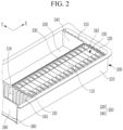
- FIG. 1 illustrates a battery module (e.g., a large module of a battery) 1000 according to an embodiment of the present invention and FIG. 2 illustrates a receiving part (e.g., a receiving unit) 220 in the battery module 1000 illustrated in FIG. 1 .
- a battery module e.g., a large module of a battery
- FIG. 2 illustrates a receiving part (e.g., a receiving unit) 220 in the battery module 1000 illustrated in FIG. 1 .
- the battery module 1000 includes a cell stack 100 and a module housing 200.
- the cell stack 100 may include a plurality of unit cells 110 aligned (or arranged) in (or along) a first direction X and an insulating member 112 around (or surrounding) the plurality of unit cells 110.
- the module housing 200 may include a plurality of receiving parts 220 into which the cell stacks 100 are inserted and aligned (or arranged) in the first direction X and a second direction Y perpendicular to the first direction X.
- the receiving part 220 includes a fixing wall 250 around (or surrounding) the cell stack 100 and having at least a portion which is in contact with the cell stack 100.
- the cell stack 100 includes the plurality of unit cells 110 arranged (e.g., aligned or stacked) in the first direction X.
- Each of the unit cells 100 may include an electrode assembly, and correspond to one secondary battery including a terminal part, and may include a case having any suitable shape, such as a rectangular shape, a cylindrical shape, or the like.
- FIGS. 1 and 2 illustrate the unit cells 110 each having a case having a rectangular pillar-shaped case, but the unit cells 110 are not necessarily limited thereto, and the unit cells 110 may have any suitable shape.
- the unit cells 110 are described as each having a rectangular shaped-case, as illustrated in FIGS. 1 and 2 .
- the plurality of unit cells 110 are arranged (e.g., aligned) in the cell stack 100 in (e.g., along) any suitable alignment direction, but in some embodiments, the plurality of unit cells 110 may be arranged (e.g., aligned) in (e.g., along) a direction in which relatively wider side surfaces among the side surfaces of the unit cells 110 face each other, as illustrated in FIGS. 1 and 2 .
- the alignment direction of the unit cells 110 is hereinafter defined as the first direction X.
- the unit cells 110 or end supports 120 may be disposed at both ends of the cell stack 100 in the first direction X.
- the number of unit cells 110 configuring the cell stack 100 may be varied as necessary or desired.
- the unit cells 110 included in one cell stack 100 may be electrically connected to each other through bus bars 436 (see FIG. 6 ) having any suitable shape.
- the cell stack 100 includes an insulating member 112 around (or surrounding) the plurality of unit cells 110.
- the insulating member 112 may be formed of an insulating material such as rubber, plastic, or the like, and is located around (or surround) the plurality of unit cells 110.
- the insulating member 112 may also be provided around (or to surround) the end supports 120 disposed at both ends of the cell stack 100 in the first direction X together with the plurality of unit cells 110, or may be around (or surround) only the plurality of unit cells 110 (and not the end supports 120), and the end supports 120 may also be separately disposed at both ends of the cell stack 100.
- the insulating member 112 may be provided in a film form or may also have a plurality of plate-shaped configurations having rigidity, for example.
- the insulating member 112 may be provided in the form surrounding all four side surfaces of the cell stack 100, or may be disposed only on a portion of the four side surfaces, and may also be provided around (or to surround) both the upper surface and the lower surface of the cell stack 100.
- the insulating member 112 disposed on the upper surface of the cell stack 100 may be provided to expose the terminal part of each of the unit cells 110.
- FIG. 1 illustrates an embodiment in which the insulating member 112 is provided in the form of an insulating film and is provided around (or to surround) the side surfaces of the plurality of unit cells 110 and is not around (or does not surround) the end supports 120 in the cell stack 100.
- the module housing 200 includes a plurality of receiving parts 220 into which the cell stacks 100 are each inserted (or received).
- FIG. 1 illustrates an embodiment in which four receiving parts 220 are formed in the module housing 200
- FIG. 2 separately illustrates two receiving parts 220 in the module housing 200 illustrated in FIG. 1 .
- any suitable number of receiving parts 220 may be formed in the module housing 200.
- the module housing 200 has an outer wall 210 extending upwardly from a bottom surface (or a floor surface) 260 and around (or surrounding) the bottom surface 260, and an inner space is defined inside (or by) the outer wall 210.
- the plurality of receiving parts 220 may be formed (or provided) in the inner space.
- the module housing 200 may have any suitable shape, for example, the module housing 200 according to an embodiment of the present invention may be provided to have a bottom surface 260 having a substantially rectangular shape, as illustrated in FIGS. 1 and 2 .
- An upper portion of the module housing 200 may be open, and accordingly, the receiving part 220 formed in the module housing 200 may also have an upper portion of the receiving part 220 that is open.
- a module cover may be coupled to and seal the open upper surface of the module housing 200, and when the module cover is coupled to the module housing 200, the module cover corresponds to an upper surface of the receiving part 220.
- the module cover may include a bus bar holder for covering the cell stack 100, and bus bars arranged in the bus bar holder to electrically connect the unit cells 110 constituting the cell stack 100.
- FIGS. 1 and 2 illustrate the receiving part 220 according to an embodiment of the present invention.
- the receiving part 220 includes the fixing wall 250 surrounding the cell stack 100 and having at least a portion which is in contact with the cell stack 100.
- FIG. 1 illustrates an embodiment where the receiving part 220 (e.g., a first receiving part 220), into which the cell stack 100 is inserted, and the receiving part 220 (e.g., a second receiving part 220), into which the cell stack 100 is not inserted, are disposed in parallel with each other.
- the fixing wall 250 corresponds to a boundary wall around (or surrounding) a region of the receiving part 220, and the cell stack 100 inserted into the receiving part 220 stably maintains a fixed state with the fixing wall 250 around (or surrounding) the cell stack 100 on four sides.
- the fixing wall 250 may be variously disposed according to the form of the cell stack 100, but may be disposed around (or to surround) the cell stack 100 while having four surfaces facing and supporting side surfaces in four directions of the cell stack 100, as illustrated in FIG. 1 .
- At least a portion of the fixing wall 250 of the receiving part 220 may be in direct contact with the cell stack 100.
- any one of the surfaces of the fixing wall 250 positioned in the first direction X may also be in direct contact with the cell stack 100, and any one of the surfaces of the fixing wall 250 positioned in the second direction Y perpendicular to the first direction X may also be in direct contact with the side surfaces of the plurality of unit cells 110, for example, the insulating member 112.
- the second direction Y may be defined as a direction perpendicular to the first direction X on the same plane as that of the first direction X, and may be defined as a width direction of the unit cell 110, as illustrated in FIG. 1 .
- the cell stack 100 may maintain a shape thereof by the fixing wall 250 even without a separate component, and may maintain an engaged state (e.g, a pressurized state or a pressed state) in the first direction X.
- an engaged state e.g, a pressurized state or a pressed state
- a module frame is coupled to one cell stack, and one cell stack to which the module frame is coupled and which is handled as a unit configuration configures one modules.
- the general cell stack may be coupled to the module frame for a performance aspect, such as energy density and ease of handling, and the module frame may include end blocks pressurizing (or pressing) both ends of the cell stack and side plates extending along side surfaces of the cell stack, and the end blocks and the side plates are coupled to each other such that the cell stack is pressed (or pressurized), thereby making it possible to maintain the structure of the cell stack.
- the module frame may include end blocks pressurizing (or pressing) both ends of the cell stack and side plates extending along side surfaces of the cell stack, and the end blocks and the side plates are coupled to each other such that the cell stack is pressed (or pressurized), thereby making it possible to maintain the structure of the cell stack.
- the cell stack coupled with the module frame is inserted and the module housing is fastened to the module frame, and the general battery module has the power amount provided by one cell stack.
- a plurality of battery modules needs to be provided so as to meet higher power demanded than that of one cell stack, and thus, a module frame fastening the cell units into a unit body and a plurality of components configuring a module itself are additionally required.
- the battery module when used in an electrical energy consumption device such as an electric vehicle (EV) requiring high power, a process for manufacturing the battery module may be increased, the consumption for the components may be increased, a weight of the battery module may be increased, and the time and cost required for manufacturing the battery module may be increased.
- EV electric vehicle
- the battery module 1000 provides a high demand power because the plurality of cell stacks 100 are mounted in one module, and because the cell stack 100 is fixed by the fixing wall 250 of the receiving part 220, of which at least a part is distinguishable (or differentiated) from the outer wall 210 of the module housing 200, a component for fixing the cell stack 100 (e.g., the module frame) is not separately required (or needed).
- the plurality of receiving parts 220 are included in module housing 200, the fixing wall 250 around (or surrounding) the receiving part 220 is provided to fix each cell stack 100 while being around (or surrounding) the same, unlike the outer wall 210 of the module housing 200.
- the module housing 200 may include end walls 240 that extend in the second direction Y and may be disposed at both ends of each of the plurality of receiving parts 220 in the first direction X to engage (e.g., to press) the end surfaces at both sides of the cell stack 100 in the first direction X, and may correspond to a part of the fixing wall 250.
- the side surfaces of both ends of the cell stack 100 in the first direction X are defined as the end surfaces, respectively.
- the end surface may correspond to the insulating member 112 or one surface of the end support 120.
- FIGS. 1 and 2 illustrate a configuration in which the end walls 240 are disposed at both sides of the cell stack 100 in the first direction X, respectively.
- a plurality of end walls 240 may exist in the module housing 200 and may correspond to both sides of the fixing wall 250 of the receiving part 220 in the first direction X.
- the end wall 240 may be distinguished from the outer wall 210 of the module housing 200.
- the end wall 240 has a shape protruding from the bottom surface 260 in the inner space of the module housing 200 and extends in the second direction Y.
- the end walls 240 may include a first end wall 240 and a second end wall 240.
- the first end walls 240 may be disposed so as to be spaced apart from the outer wall 210 facing one surface, and the second end walls 240 may face each other, as discussed further below.
- FIG. 1 illustrates an embodiment including a plurality of receiving parts 220, for example a total of four receiving parts 220, with two in the first direction X and two in the second direction Y, and one separation wall 230 that crosses a portion of the inner space of the module housing 200 in the first direction X and four end walls 240 extending in the second direction Y.
- a plurality of receiving parts 220 for example a total of four receiving parts 220, with two in the first direction X and two in the second direction Y, and one separation wall 230 that crosses a portion of the inner space of the module housing 200 in the first direction X and four end walls 240 extending in the second direction Y.
- the separation wall 230 is shared by the receiving parts 220 adjacent to each other (or stacked) in the second direction Y, but the end walls 240 are not shared by adjacent receiving parts 220 stacked in the first direction X. Instead, respective end walls 240 (e.g., the second end walls 240) are disposed to be spaced apart from each other and to face each other at ends of the two receiving parts 220 that face each other in the first direction X.
- the end wall 240 may be disposed so that one surface (e.g., a first surface) thereof makes contact with an end surface of the cell stack 100 inserted into a corresponding receiving part 220 and an opposite surface (e.g., a second surface) thereof is spaced apart from the outer wall 210 and faces the other wall 210 or the end wall 240 of another receiving part 220 that is disposed in parallel in the first direction X.
- one surface e.g., a first surface
- an opposite surface e.g., a second surface
- a pair of end walls 240 disposed at both sides of the receiving part 220 in the first direction X is in direct contact with the end surface of the cell stack 100 facing each other, for example, at least a portion of one surface of the end support 120.
- the end wall 240 may be disposed to engage (e.g., to press) the cell stack 100 in the first direction X.
- the cell stack 100 inserted into the receiving part 220 is not fastened to the module frame, such as the end block or the side plate, but the insulation member 112 may be around the lateral surfaces of the cell stack 100 where the plurality of unit cells 110 is arranged (or aligned only aligned), and in the battery module 1000 according to an embodiment of the present invention, the end walls 240 may serve to engage (e.g., to press) and fix the cell stack 100 in the first direction X.
- the cell stack 100 is engaged (e.g., pressed) in the first direction X to provide higher power under the same volume, and may be maintained in a structurally stable state.
- the cell stack 100 may be inserted between the fixing walls 250 of the receiving part 220, e.g., between the pair of end walls 240 provided at both sides in the first direction X, in an engaged (or pressed) state by a jig inserted into the receiving part 220 in a state in which the end surface is engaged (or pressed).
- FIG. 3 illustrates a plurality of battery modules 1000 according to the embodiment of the present invention that are coupled with adjacent battery modules.
- FIG. 3 illustrates a plurality of battery modules 1000 that are coupled with each other to form a large pack.
- each of the battery modules 1000 may further include a coupling part 400, which is provided at the module housing 200 and is coupled with an adjacent battery module 1001 (e.g., an adjacent module housing).
- a coupling part 400 which is provided at the module housing 200 and is coupled with an adjacent battery module 1001 (e.g., an adjacent module housing).
- a plurality of receiving parts 220 are provided in a module housing 200 so that high output is efficiently implemented by including the plurality of cell stacks 100.
- power required from an electrical energy consumption device may offset an output provided from the battery module 1000 according to an embodiment of the present invention.
- FIG. 5 illustrates an embodiment where the coupling part 400 (e.g., a guide part 420) is formed on one surface of the module housing 200, and the coupling parts 400 (e.g., the guide parts 420) of the battery module 1000 and the adjacent battery module 1001 are coupled to each other.
- the coupling part 400 e.g., a guide part 420
- the coupling part 400 may be provided in any suitable type or shape.
- FIG. 3 illustrates fastening parts 410 that are fastened to each other through a fastening member 415, the guide parts 420 which align positions of the respective fastening parts 410 of the corresponding battery module 1000 and the adjacent battery module 1001, and connection parts 430, which are connection passages of the bus bar 436 (see FIG. 6 ) for electrical connection with the adjacent battery module 1001 according to an embodiment of the present invention.
- the outer walls 210 may include a first wall 211 and a second wall 212 positioned in the second direction Y (or spaced apart along the second direction Y) among the outer walls 210 of the module housing 200.
- the coupling parts 400 may be provided on the first wall 211 and the second wall 212, and the coupling part 400 provided on the second wall 212 of the module housing 200 of the battery module 1000 may be configured to be coupled to the coupling part 400 provided on the first wall 211 of the adjacent battery module 1001.
- the coupling parts 400 may be included in the module housing 200, as shown in FIG. 3 , and may be disposed at an outer wall 210 of the module housing 200.
- the coupling parts 400 may be formed at two facing surfaces among the four surfaces of the outer wall 210 so that a plurality of battery modules 1000 may be coupled to each other.
- the module housing 200 may have a cross section of a rectangular shape having a longer length in the first direction X.
- the coupling parts 400 may be disposed at the first wall 211 and the second wall 212 located in a second direction Y among the outer walls 210 of the module housing 200 so that an entire length of the plurality of module housings 200 may be reduced, even if a plurality of module housings 200 are aligned in a line and coupled through the coupling parts 400.
- a cross sectional shape of the module housing 200 or a location of an outer wall 210 in which the coupling part 400 is disposed are not necessarily limited thereto.
- the coupling part 400 disposed on the first wall 211 of any one of the module housings 200 may be coupled to (or may be configured to be coupled to) the coupling part 400 disposed on the second wall 212 of an adjacent module housing facing the first wall 211, and the coupling part 400 disposed on the second wall 212 of any one of the module housings 200 may be coupled to (or may be configured to be coupled to) the coupling part 400 disposed on the first wall 211 of the adjacent module housing facing the second wall 212.
- the coupling part 400 disposed at the first wall 211 in the module housing 200 of the battery module 1000 may be inserted into and coupled to the coupling part 400 of the adjacent battery module 1001.
- the fastening part 410, a guide pin 422 of the guide part 420, and a connection tube 432 that defines a connection tunnel of the connection part 430 may be disposed on the first wall 211.
- the coupling part 400 disposed at the second wall 212 may be coupled to the coupling part 400 of the adjacent battery module 1001 by inserting the coupling part 400 of the adjacent battery module 1001 into (or inside) the coupling part 400 at the second wall 212.
- the fastening part 410, a guide groove 424 of the guide part 420, and a tube receiving opening (or tunnel insertion hole or tunnel receiving opening) 434 of the connection part 430 may be disposed in the second wall 212.
- an insertion relationship and each configuration of the coupling parts 400 disposed at the first wall 211 and the second wall 212 are not necessarily limited thereto.
- FIG. 3 illustrates the fastening part 410 of the coupling part 400 that is configured to be fastened to the adjacent battery module 1001 adjacent to the module housing 200 of the corresponding battery module 1000 according to an embodiment of the present invention
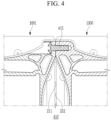
- FIG. 4 illustrates the fastening parts 410 fastened to each other between the module housing 200 of the corresponding battery module 1000 and the module housing 200 of the adjacent battery module 1001.
- the coupling part 400 includes the fastening parts 410 formed in the first wall 211 and the second wall 212, respectively.
- the fastening part 410 of the first wall 211 may be fastened to the fastening part 410 formed at the second wall 212 of the adjacent battery module 1001 through a fastening member 415.
- the fastening part 410 corresponds to a portion in which the corresponding module housing 200 of the battery module 1000 and the module housing 200 of the adjacent battery module 1001 are fastened to each other and are fixed among the plurality of components of the coupling part 400.
- the fastening parts 410 may be provided on the first wall 211 and the second wall 212 of the module housing 200, respectively, and may be provided on both end portions of the first wall 211 and the second wall 212, respectively, as illustrated in FIG. 3 .
- the fastening part 410 provided on the second wall 212 of any one of the module housings 200 may be fastened to the fastening part 410 provided on the first wall 211 of the adjacent battery module 1001, and the fastening member 415 for fastening the fastening parts 410 to each other may be provided.
- the fastening part 410 may have any suitable type or shape, and in FIG. 4 , according to an embodiment of the present invention, a fastening opening (or fastening hole) through which the fastening member 415 penetrates may be formed in the fastening part 410, and the fastening member 415 may penetrate through the respective fastening openings provided in a pair of fastening parts 410 and may be fixed to couple the corresponding module housing 200 and the adjacent battery module 1001 to each other.
- a fastening opening or fastening hole
- the fastening member 415 may be provided in various types and shapes, and FIG. 4 illustrates the fastening member 415 provided in the form of a bolt penetrating through the fastening hole according to an embodiment of the present invention.
- FIG. 5 illustrates a cross section of the guide pin 422 and the guide groove 424 after coupling to each other according to an embodiment of the present invention.
- the coupling part 400 is positioned on the first wall 211, and may include the guide pin 422 protruding in the second direction Y and the guide groove 424 positioned on the second wall 212 and in which the guide pin 422 of the adjacent battery module 1001 is inserted.
- the coupling part 400 may include the guide part 420, and the guide part 420 may be configured by the guide pin 422 and the guide groove 424.
- the guide pin 422 and the guide groove 424 may be disposed at opposite sides on the first wall 211 or the second wall 212 of the module housing 200.
- the guide pin 422 may be disposed on the first wall 211 and the guide groove 424 may be disposed on the second wall 212.
- a fixed relationship between the corresponding module housing 200 of the battery module 1000 and the adjacent battery module 1001 may be formed by the fastening part 410, and the guide part 420 may be provided so that the fastening part 410, to which the fastening member 415 is coupled, may maintain a simple and stable fastening position.
- the guide pin 422 may be formed to externally protrude along the second direction Y from the first wall 211 of the module housing 200.
- the guide pin 422 may be manufactured separately from the module housing 200 and coupled to the first wall 211, and may also be formed integrally with the module housing 200.
- the guide pin 422 may have any suitable shape.
- FIG. 3 and FIG. 5 illustrate a guide pin 422 having a substantially circular shape, but the present invention is not limited thereto.
- the guide groove 424 may be provided on (or in) the second wall 212 of the module housing 200, and may have the form of a groove recessed inwardly along the second direction Y on (or in) the second wall 212 of the module housing 200.
- a shape of a cross section of the guide pin 422 may be provided to correspond to a shape of a cross section of the guide groove 424.
- the guide pin 422 provided on the first wall 211 of the adjacent battery module 1001 is configured to be inserted into the guide groove 424 provided in the second wall 212 of any the module housing 200 of the battery module 1000 adjacent thereto, and is coupled thereto.
- the module housing 200 of the battery module 1000 and the adjacent battery module 1001 form a stable coupling position, and accordingly, when the guide pin 422 is inserted into the guide groove 424, the respective fastening parts 410 of the corresponding module housing 200 of the battery module 1000 and the adjacent battery module 1001 may be aligned at positions at which they face each other and may be fastened to each other.
- the coupling part 400 includes the guide part 420 together with the fastening part 410, thereby making it possible to easily achieve an arrangement state for coupling the two or more module housings 200 to each other.
- FIG. 6 illustrates a cross-section of the connection part 430 in the battery module 1000 according to an embodiment of the present invention.
- the coupling part 400 may further include the connection tube 432 positioned on the first wall 211, protruding in the second direction Y, and having a hollow form in which the bus bar 436 is led from the inside of the module housing 200, and the tube receiving opening 434 positioned on the second wall 212 and into which the connection tube 432 of the adjacent battery module 1001 and the bus bar 436 are inserted.
- connection of the module bus bars 436 may be required for the cell stacks 100 of each module housing 200 to be electrically connected to each other, and when the module housing 200 itself is provided with a control module for controlling a cooling performance or monitoring the unit cell 110, connection lines 438 for transmitting and receiving management control signals of the respective control modules should be connected to each other.
- connection part 430 may be included in the coupling part 400, and connection members for electrical connection or information connection between the two module housings 200 through the connection part 430 may be connected into the two module housings 200.
- connection part 430 may be configured by the connection tube 432 and the tube receiving opening 434.
- the connection tube 432 may be disposed on the first wall 211 at the outer wall 210 of the module housing 200, and the tube receiving opening 434 may be disposed on the second wall 212 at the outer wall 210 of the module housing 200.
- connection tube 432 may have a form protruding in the second direction Y from the first wall 211 like the guide pin 422, and the position of the connection tube 432 on the first wall 211 may be at any suitable location, and according to an embodiment of the present invention, the connection tube 432 may be disposed at a center side (or central area) of the first wall 211.
- connection tube 432 may be provided in a cylindrical shape having a hollow penetrating through the first wall 211, and the bus bar 436 or the connection line 438 may be led outside of the module housing 200 from inside of the module housing 200 through the hollow therein.
- the bus bar 436 is connected with a plurality of cell stacks 100 included at an inner space of the module housing 200 and is led to the outside from the inner space through the connection tube 432.
- the module bus bar 436 led through the connection tube 432 may be inserted into the adjacent battery module 1001 through the tunnel insertion hole 434 provided in the adjacent battery module 1001, and may be electrically connected to the plurality of cell stacks 100 existing in the inner space of the adjacent battery module 1001.
- the tunnel receiving opening 434 is provided on the second wall 212 like the guide groove 424, and penetrates through the second wall 212 to communicate the inside and the outside of the module housing 200 with each other.
- a cross-sectional shape of the tunnel receiving opening 434 may be a shape corresponding to the connection tube 432, and a position thereof may also be a position corresponding to the connection tube 432.
- connection tube 432 of the adjacent battery module 1001 is inserted in the tunnel receiving opening 434 of the module housing 200 to be coupled to each other.
- the bus bar 436 and the connection lines 438 led through the hollow of the connection tube 432 of the adjacent battery module 1001 are input into the module housing 200 through the tunnel receiving opening 434 of the module housing 200.
- the coupling part 400 includes the connection part 430, such that an electrical connection and a signal connection may be easily performed when the adjacent battery modules 200 are coupled to each other, and the connection members such as the bus bar 436 and the connection line 438 for electrical connection and signal connection may be effectively coupled to each other without being exposed to the outside when the adjacent battery module 1001 is coupled thereto.
- FIG. 6 illustrates an embodiment in which the connection tube 432 is inserted into the tunnel receiving opening 434 so that the bus bar 436 and the connection line 438 are positioned inside the connection part 430.
- the bus bar 436 and the connection line 438 connect a corresponding module housing 200 of the battery module 1000 with the adjacent battery module 1001.
- the fastening parts 410 may be disposed at both end portions of the first wall 211 and the second wall 212 in the first direction X, respectively, the connection tunnels 432 and the tunnel receiving openings 434 may be disposed at the central portion of the first wall 211 or the second wall 212, guide pins (422) may be disposed between the fastening part 410 and the connection tube 432, respectively, and the guide grooves 424 may be disposed between the fastening part 410 and the tunnel receiving opening 434, respectively.
- connection tunnels 432 and the tunnel receiving openings 434 are positioned at central portions of the first wall 211 and the second wall 212, respectively.
- the guide parts 420 may be disposed at both sides of the first wall 211 and the second wall 212, respectively.
- the fastening parts 410 may be positioned at both ends of the first wall 211 and the second wall 212 as an outer side of the guide part 420.
- the fastening parts 410 may be disposed at both end portions of the first wall 211 and the second wall 212 so that structural stability may be improved by the fastening parts 410, and a plurality of guide parts 420, for example, a pair of guide parts 420 may be provided and may be disposed at both sides of the central portions of the first wall 211 and the second wall 212 so that a guide effect by the guide parts 420 is increased.
- the connection part 430 may be disposed at the central portions of the first wall 211 and the second wall 212 to lead and connect (e.g., easily lead and connect) the module bus bar 436 and the connection line 438.
- positional characteristics of the components of the coupling part 400 may be changed or modified, as necessary or desired.
- FIG. 12 illustrates a figure in which a plurality of battery modules according to another embodiment of the present disclosure are provided and are interconnected. That is, FIG. 12 illustrates a figure in which the battery modules are coupled to each other to form a large pack (e.g., a battery pack).
- a large pack e.g., a battery pack
- the coupling parts 400 are formed on the upper surface (or module cover) and the bottom surface of the battery module, and the coupling parts 400 between the battery modules adjacent to each other are coupled to each other. Accordingly, the plurality of battery modules may be stacked in the vertical direction (directions perpendicular to the first direction X and the second direction Y) through the coupling parts 400.
- connection part 430 e.g., the connection tube
- connection part 430 e.g., the tube receiving opening
- connection parts 430 may be connection passages of the module bus bar and the connection line.
- the module housing 200 may further include the separation wall 230 extending in the first direction X and partitioning the inner space surrounded by the outer wall 210 to contribute to form the plurality of receiving parts 220.
- the separation wall 230 may configure (or form) a portion of the fixing walls 250 of the two receiving parts 220 disposed at both sides along the second direction Y, and may be in contact with the side surfaces of the cell stack 100 inserted into each of the two receiving parts 220.
- the side surfaces refer to both side surfaces extending in the first direction X among the side surfaces of the cell stack, for example, both side surfaces of the cell stack 100 in the second direction Y, and as described above, because the cell stack 100 according to the present invention does not include the separate module frame, the side surfaces may correspond to the insulating member 112 surrounding the side surfaces of the plurality of unit cells 110.
- the separation wall 230 may protrude upwardly from the bottom surface 260 of the module housing 200, and may be provided to divide the inner space of the module housing 200 while extending along the first direction X.
- the separation wall 230 may correspond to a portion of the fixing wall 250 surrounding (or around) the receiving part 220, e.g., one surface thereof.
- the receiving parts 220 may be formed at both sides of the separation wall 230, and the separation wall 230 becomes (or forms) the fixing wall 250 for the two receiving parts 220 formed at both sides thereof.
- the separation wall 230 faces the side surfaces of the cell stack 100 inserted into the receiving part 220, and accordingly, the separation wall 230 corresponding to a portion of the fixing wall 250 is in direct contact with at least a portion of the side surfaces of the cell stack 100 inserted into the receiving part 220 to thereby support the cell stack 100 in the second direction Y.
- FIG. 7 illustrates a cross section of the end wall 240 spaced apart from the outer wall 210 of the module housing 200.
- the end wall 240 may be disposed so that a surface thereof (e.g., a surface of a second side thereof) faces the outer wall 210 of the module housing 200, may be spaced apart from the outer wall 210 along the first direction X to form a first space (e.g., a first impact absorbing space) 215 between the outer wall 210 and the end wall 240.
- a first space e.g., a first impact absorbing space
- a plurality of end walls 240 may be provided, as illustrated in FIGS. 1 and 2 , and the end wall 240 facing the outer wall 210 from among the plurality of end walls 240 may be spaced apart from the outer wall 210 of the module housing 200 facing the end wall 240 in the first direction X, as illustrated in FIG. 7 to form the first space 215 between the outer wall 210 of the module housing 200 and the end wall 240.
- FIG. 2 and FIG. 7 illustrate the end wall 240 facing the outer wall 210 of the module housing 200 from among the end walls 240 constituting the fixing wall 250 of the receiving part 220, and illustrate an embodiment in which the first space 215 is formed between the end wall 240 and the outer wall 210.
- FIG. 7 illustrates the first space 215 shown in FIG. 2 viewed from a top view.
- the module housing 200 protects (or safely protects) the cell stack 100 inserted into the receiving part 220 against an impact transferred from outside of the module housing 200, and in the embodiment of the present invention, the first end wall 240, which is in direct contact with the end surface of the cell stack 100 and supports and engages (e.g., presses) the cell stack 100, is spaced apart from the outer wall 210, thereby preventing the impact transferred to the outer wall 210 from being directly transferred to the first end wall 240, or reducing the likelihood thereof.
- the first space 215 may provide (or advantageously serve as) a heat dissipating space in which the heat of the cell stack 100 is dispersed.
- a plurality of receiving parts 220 may be disposed in the inner space of the module housing 200 along the first direction X, and the two receiving parts 220 adjacent to each other along the first direction X each include one of the end walls 240 which face each other in the first direction X (e.g., the second end walls 240) and may be spaced apart from each other in the first direction X to form a second space (e.g., a second impact absorbing space) 216 between the second end walls 240.
- a second space e.g., a second impact absorbing space
- FIG. 1 illustrates the module housing 200 including four receiving parts 220, and sets of two receiving parts 220 are aligned (or arranged) in the first direction X.
- the present invention is not limited thereto, and any suitable number of receiving parts 220 may be aligned (or arranged) in the first direction X.
- the fixing wall 250 (or the end wall 240) of one receiving part 220 faces the fixing wall 250 (or the end wall 240) of the other receiving part 220, and the two receiving parts 220 have different end walls 240 that face each other (e.g., different second end walls 240 that face each other).
- the receiving parts 220 arranged in the first direction X do not share the end walls 240.
- the two receiving parts 220 may be arranged (or aligned) in the first direction X, the second end walls 240 may be spaced apart from each other, and the second space 216 may be formed between the second end walls 240.
- the second space 216 protects the cell stack 100 inserted into the corresponding receiving part 220 from an impact delivered from the outside of the receiving part 220, much like the first space 215.
- the first space 215 may prevent an impact delivered to the outer wall 210 of the module housing 200 from being delivered to the inner space of the module housing 200, or reduce the likelihood thereof
- the second space 216 may prevent the impact delivered to any one of the receiving parts 220 (e.g., the first receiving part 220) from being delivered to the other receiving part 220 adjacent to the first receiving part 220 (or the second receiving part 220) in the first direction X, or reduce the likelihood thereof.
- the end support 120 may be disposed at an outer side of the outermost cell of the cell stack 100.
- FIG. 9 illustrates an end surface (or an outer surface) of the end support 120.
- the cell stack 100 may further include a pair of end supports 120 disposed at both (or opposite) end portions in the first direction X, respectively, and having the outer side surfaces corresponding to the end surfaces of the cell stack 100.
- the plurality of unit cells 110 may be provided such that at least the lateral surface is surrounded by the insulation member 112 (or the insulation member 112 is around at least the lateral surface of the plurality of unit cells 110), and the end supports 120 may be disposed in such that an interior surface (or inner surface) of each of the end supports 120 is in surface contact with the insulation member 112, at both ends of the cell stack 100 in the first direction X.
- the present invention is not limited thereto.
- the end supports 120 are disposed at both ends of the cell stack 100 in the first direction X, and the exterior surfaces of the end supports 120 may correspond to end surfaces of the cell stack 100.
- the end support 120 may serve to absorb impact between the end wall 240 and the outermost cell, and may serve to uniformly transfer force (e.g., pressing force) of the end wall 240 to the outermost cell among the plurality of unit cells 110.
- the outermost cell refers to the unit cell 100 positioned at the outermost side in the first direction X among the plurality of unit cells 110 configuring the cell stack 100, and in the embodiment of the present invention, the outermost cell is disposed at each end of the cell stack 100 in the first direction X.
- an entire surface of the end wall 240 may not press the end support 120 (e.g., because the end wall 240 has a bent (or curved) shape), an entire surface of the end support 120 may press the insulation member 112 and the exterior surface (or outer surface) of the outermost cell.
- FIG. 7 illustrates the cross-section of the end wall 240, which is bent (or curved) so that the center portion is far from the end surface
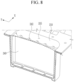
- FIG. 8 illustrates an inner surface of the end surface of the cell stack 100 at the curved end wall 240 according to embodiments.
- the end wall 240 may be outwardly bent (or curved) so that a central portion thereof is further from the facing (or adjacent) end surface facing of the cell stack 100, thereby forming a third space 217 (e.g., a swelling space) between the end wall 240 and the end surface.
- a third space 217 e.g., a swelling space
- the end wall 240 may be formed in a bent (or curved) shape such that the central portion thereof is further from the end surface of the cell stack 100 inserted into the receiving part 220.
- the end wall 240 may be recessed only in the center part thereof with respect to the second direction Y and a third direction (e.g., a height direction), but may be provided in a bent (or curved) shape so that a cross section thereof has a recessed shape, as shown in FIG. 7 .
- the end wall 240 has the bent (or curved) shape so that a space is formed in (or at) at least the central portion between the end wall 230 and the end surface of the cell stack 100, and the corresponding space corresponds to the third space 217 according to an embodiment of the present invention.
- a swelling phenomenon may occur in which a gas is generated from an internal electrode assembly and swelled due to the endurance progress of use (e.g., repeated use) or a surrounding (or peripheral) situation (e.g., by swelling of an adjacent unit cell 110), and it is particularly important in a structure in which the plurality of unit cells 110 are aligned to implement a structure capable of appropriately coping with the swelling.
- the swelling phenomenon when the swelling phenomenon occurs in one unit cell 110, the swelling phenomenon may occur in other unit cells 110 of the cell stack 100 including a corresponding unit cell 110. If the swelling phenomenon occurs in one unit cell 110 to increase a thickness of the unit cell 110, the whole length of the cell stack 100 may be greatly changed in view of all of a plurality of unit cells 110. Further, the length change of the cell stack 100 may be applied to the end wall 240 pressurizing the cell stack 100 in the first direction X to cause breakage.
- the unit cells 110 When the swelling phenomenon occurs, the unit cells 110 have a large amount of expansion in the center portion of the lateral surface positioned in the first direction X according to a structural characteristic, and thus, in the embodiment of the present invention, the third space 217 is formed between the end wall 240 and the end surface so as to accommodate the expansion of the volume of the cell stack 100 according to the swelling when the swelling phenomenon of the cell stack 100 occurs, for example.
- the cell stack 100 is engaged (e.g., pressed) in the first direction X for efficiency, such as energy density, and in the embodiment of the present invention, even though the center portion of the end wall 240, which engages (e.g., presses) the end surface, is curvedly bent, both end portions of the end wall 240 maintain the engaged state (e.g., pressed state) of the end surfaces, which assists operation of the cell stack 100.
- the end surface of the end support 120 may be indented inwardly so that the center portion of the end surface of the end support 120 is relatively far from the facing end wall 240.
- the end support 120 may have a shape in which the center portion of the end surface is indented.
- the end surface of the end support 120 be shaped such that the center portion of the end surface is indented, so that a space is formed in at least the center portion between the end surface of the end support 120 and the end wall 240 similar to the end wall 240 having the bent (or curved) shape, and thus the third space 217 may be formed in at least the center portion between the end support 120 and the end wall 240.
- a swelling phenomenon may occur in at least one of the plurality of unit cells 110, for example, a central portion of the unit cell 110 may swell or expand, and the central portion of the end support 120 presses the end wall 240 side due to the expansion of the central portions of the plurality of unit cells 110. Because the central portion of the end surface of the end support 120 has a structure recessed inwardly, even when the central portion of the end support 120 is pressed and transformed outwardly, transformation or damage of the end wall 240 may be suppressed or prevented (or the likelihood thereof may be reduced) by the third space 217 formed between the end support 120 and the end wall 240.
- a plurality of first ribs 242 may be formed on the end wall 240 according to an embodiment of the present invention.
- the end wall 240 may include the plurality of first ribs 242 on the outer side surface thereof with respect to (or in) the first direction X.
- the end wall 240 should be robust against external impact while engaging (e.g., pressing) the end surface of cell stack 100, and further, even though the third space 217 is formed, even when a change in length of the cell stack 100 occurs beyond an accommodating range of the third space 217, the end wall 240 should have mechanical strength to prevent breakage, or reduce the likelihood thereof.
- the plurality of first ribs 242 may be provided on (or at) the outer side surface of the end wall 240, e.g., the surface facing the outer wall 210, or a surface opposite to the cell stack 100.
- the first ribs 242 are formed on the outer side surface of the end wall 240 to protect the cell stack 100.
- the outer side surface of the end wall 240 refers to a surface facing the opposite side of the end support 120.
- the first ribs 242 may be separately manufactured and may be coupled to the end wall 240, or may be formed integrally on the end wall 240, for example, through a casting process.
- the plurality of first ribs 242 may extend in the third direction (e.g., the height direction) of the end wall 240 and may be disposed to be spaced apart from each other in the second direction Y.
- the first ribs 242 may extend in the third direction of the end wall 240. Accordingly, the first ribs 242 may effectively improve strength of the end wall 240 and may be formed integrally with the end wall 240, e.g., in a casting process using an upper mold and a lower mold.
- FIG. 7 illustrates cross sections of the plurality of first ribs 242 disposed to be spaced apart from each other along the second direction Y.
- FIG. 9 illustrates the end support 120 having a plurality of second ribs 122 formed on the end surface thereof.
- the end support 120 in an embodiment of the present invention may include the plurality of second ribs 122 protruding toward the end wall 240 on the end surface of the end support 120.
- the end support 120 should be robust against deformation and breakage while coping with the expansion of the unit cells 110 due to the swelling phenomenon.
- the second ribs 122 are formed on the end surface of the end support 120 to improve robustness of the end support 120.
- an inner side surface of the end support 120 e.g., an opposite surface of the end surface, is in surface contact with the outer side surface of the outermost cell of the cell stack 100 or the insulating member 112 to secure pressurization capability, and the second ribs 122 are formed on the end surface of the end support 120.
- the second ribs 122 may be disposed to be spaced apart from each other in the second direction Y and the third direction of the end support 120 to form a lattice shape.
- the second ribs 122 may be formed to cross substantially the entire end surface along an extending direction, and some of the plurality of second ribs 122 may extend in the second direction Y and the remainder thereof may extend in the third direction of the end support 120, such that the plurality of second ribs 122 may be disposed to form a lattice shape.
- a plurality of second ribs 122 may be spaced apart from each other in the second direction Y or the third direction of the end support 120 so as to form a lattice shape, which may effectively improve strength of the end support 120.
- substantially square-shaped grooves may be disposed in a lattice form on the end surface of the end support 120, and the second ribs 122 may be separately manufactured and coupled to the end surface of the end support 120, or may be formed integrally when the end support 120 is manufactured.
- the fixing wall 250 of any one of the receiving parts 220 may be defined as including the separation wall 230, the pair of end walls 240, and a portion of the outer wall 210, and the separation wall 230 and the end walls 240 may be formed integrally, for example, through a casting process or the like.
- one surface of the four surfaces of the fixing wall 250 may correspond to the separation wall 230, two other surfaces may correspond to the end walls 240, respectively, and the remaining surface may constitute the outer wall 210 of the module housing 200.
- the module housing 200 may have the bottom surface 260 formed integrally with the end walls 240, the separation wall 230, and the outer wall 210, e.g., through the casting process.
- the end walls 240 and the separation wall 230 may be formed integrally with the module housing, and engraving (or intaglios) of the end wall 240 and the separation wall 230 may be integrally formed in the mold when the mold is manufactured for the casting process.
- the end walls 240 and the separation wall 230 may be formed integrally with the outer wall 210 of the module housing 200.
- the outer wall 210, the separation wall 230, the end walls 240, and the bottom surface 260 of the module housing 200 may be all manufactured (or formed) integrally.
- a manufacturing process where a module housing 200 including the end wall 240 and the separation wall 230, which are integrally formed, an additional manufacturing process for including the end wall 240 and the separation wall 230 may be omitted.
- the cell stack 100 of the present invention may fix (e.g., stably fix) a plurality of unit cells 110 inside the receiving part 220 in a pressed state.
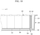
- FIG. 10 illustrates a cross-section of the module housing 200 according to an embodiment of the present invention, and illustrates a cooling channel 300 having a flow space 310, in which coolant flows, formed under the bottom surface 260 of the module housing 200.
- FIG. 11 illustrates the cooling channel 300 viewed from the bottom side.
- the module housing 200 may be formed with the cooling channel 300, through which coolant flows, under the bottom surface 260. Further, a plurality of guide ribs (or guide protrusions) 350 extending in a flowing direction of the coolant and guiding a flow of the coolant, may be provided on a lower surface of the bottom surface 260, as illustrated in FIG. 11 .
- the flow space 310 of the cooling channel 300 may be formed throughout an entirety of the bottom surface 260, or may be formed to correspond to a cross-sectional area of the internal space of the module housing 200, in which the receiving part 220 is formed.
- the cooling channel 200 may be designed such that the flow space 310 is not formed below the first space 215.
- the coolant flows inside the cooling channel 300, and various refrigerants, such as air or cooling water, may also be used.
- the unit cell 110 configuring the cell stack 100 corresponds to a heating body emitting heat at the time of the discharge, and when a temperature of the unit cell 110 is excessively increased, the swelling phenomenon may be induced or heat may be increased (e.g., rapidly increased) through a rapid chemical reaction, so that a thermal runaway phenomenon generating fire and the like may be generated.
- the cell stack 100 in which the plurality of unit cells 110 is arranged, is used like the embodiment of the present invention, when the thermal runaway phenomenon is generated in any one unit cell 110, a thermal runaway dispersion phenomenon influencing another peripheral unit cell 110 may be generated.
- the battery module 1000 includes the cooling channel 300 under the bottom surface 260 of the module housing 200 and may efficiently implement cooling of each (or all) of the plurality of cell stacks 100.
- the cooling channel 300 is formed under the bottom space 260 of the module housing 200, e.g., in the space divided from the internal space of the module housing 200, as opposed to the inside of the module housing 200, so that it is possible to more easily repair and manage the cooling channel 300.
- the cooling channel 300 when a module cover of the module housing 200 is assembled, it is possible to easily repair and manage the cooling channel 300 at a lower portion of the module housing 200.
- the lateral (e.g. side) wall 320 of the cooling channel 300 protrudes from the bottom surface 260 in a downward direction (or a direction opposite to the third direction), extends along a border of the bottom surface 260, and is formed to surround the bottom surface 260, and a channel cover 330 is coupled to a lower end of the lateral wall 320 to seal the cooling channel 300.
- the lateral wall 320 of the cooling channel 300 may be integrally formed with the bottom surface 260 of the module housing 200, e.g., through the cast process, and the channel cover 330 may be welded and coupled to the lateral wall 320 of the cooling channel 300.
- FIG. 10 illustrates the lateral wall 320 of the cooling channel 300 extending along the border of the bottom surface 260 of the module housing 200 and surrounding the bottom surface 260, and protruding from the bottom surface 260 in the downward direction.
- the lateral wall 320 of the cooling channel 300 is integrally formed with the bottom surface 260 of the module housing 200, e.g., through the cast process, so that a coupling region between the lateral wall 320 and the bottom surface 260 is not needed (or does not exist), and thus, it is possible to prevent the coolant from unintentionally leaking into the module housing 200, or to reduce the likelihood thereof.
- the channel cover 330 sealing the cooling channel 300 may be coupled to the lateral wall 320 of the cooling channel 300 by any suitable method, such as welding, and a border of the channel cover 330 may be coupled to the lower end of the lateral wall 320.
- FIG. 11 illustrates the cooling channel 300 viewed from the bottom side with the channel cover 330 removed.
- a lateral wall 320 of the cooling channel 300 protrudes downward from the bottom surface 260 of the module housing 200.
- An open lower portion of the cooling channel 300 is coupled to the channel cover 330 to form a closed cooling channel 300. Danger in an operation of the cell stack 100 due to leakage of cooling water in the cooling channel 300 may be efficiently reduced by forming the cooling channel 300 at an outside of the module housing 200.
- the outer wall 210 and the bottom surface 260 of the module housing 200 and the lateral wall 320 of the cooling channel 300 may all be formed integrally, e.g., through the casting process, such that there is no portion through which the cooling water may leak, and further, because the cooling channel 300 is provided below the bottom surface 260 of the module housing 200, e.g., to the outside of the inner space of the module housing 200, it is possible to prevent a situation in which the cooling water leaks into the inner space of the module housing 200 in which the cell stacks 100 are located, even when there is leakage of the cooling water generated (e.g., unintentionally generated) in the cooling channel 300.
- the cooling water generated e.g., unintentionally generated
- the assembly process and components may be simplified, high power demand may be effectively satisfied, the plurality of cell stacks 100 may be effectively cooled through the cooling channel 300, and the plurality of cells stacks 100 may be effectively protected from a leakage phenomenon of the cooling water, which may be caused in the cooling channel 300.
Landscapes
- Chemical & Material Sciences (AREA)
- Chemical Kinetics & Catalysis (AREA)
- Electrochemistry (AREA)
- General Chemical & Material Sciences (AREA)
- Engineering & Computer Science (AREA)
- Manufacturing & Machinery (AREA)
- Battery Mounting, Suspending (AREA)
Applications Claiming Priority (2)
| Application Number | Priority Date | Filing Date | Title |
|---|---|---|---|
| KR1020180125550A KR102646854B1 (ko) | 2018-10-19 | 2018-10-19 | 배터리 모듈 |
| EP19203926.1A EP3641004B1 (de) | 2018-10-19 | 2019-10-17 | Batteriemodul |
Related Parent Applications (2)
| Application Number | Title | Priority Date | Filing Date |
|---|---|---|---|
| EP19203926.1A Division EP3641004B1 (de) | 2018-10-19 | 2019-10-17 | Batteriemodul |
| EP19203926.1A Division-Into EP3641004B1 (de) | 2018-10-19 | 2019-10-17 | Batteriemodul |
Publications (2)
| Publication Number | Publication Date |
|---|---|
| EP4277008A2 true EP4277008A2 (de) | 2023-11-15 |
| EP4277008A3 EP4277008A3 (de) | 2025-04-30 |
Family
ID=68296015
Family Applications (2)
| Application Number | Title | Priority Date | Filing Date |
|---|---|---|---|
| EP19203926.1A Active EP3641004B1 (de) | 2018-10-19 | 2019-10-17 | Batteriemodul |
| EP23194224.4A Pending EP4277008A3 (de) | 2018-10-19 | 2019-10-17 | Batteriemodul |
Family Applications Before (1)
| Application Number | Title | Priority Date | Filing Date |
|---|---|---|---|
| EP19203926.1A Active EP3641004B1 (de) | 2018-10-19 | 2019-10-17 | Batteriemodul |
Country Status (6)
| Country | Link |
|---|---|
| US (2) | US11626630B2 (de) |
| EP (2) | EP3641004B1 (de) |
| KR (1) | KR102646854B1 (de) |
| CN (3) | CN117438726A (de) |
| HU (1) | HUE065332T2 (de) |
| PL (1) | PL3641004T3 (de) |
Families Citing this family (24)
| Publication number | Priority date | Publication date | Assignee | Title |
|---|---|---|---|---|
| KR102259219B1 (ko) | 2018-07-03 | 2021-05-31 | 삼성에스디아이 주식회사 | 리튬 이차 전지 |
| KR102259218B1 (ko) | 2018-07-03 | 2021-05-31 | 삼성에스디아이 주식회사 | 리튬 이차 전지용 전극, 및 이를 포함하는 리튬 이차 전지 |
| KR102323950B1 (ko) | 2018-12-12 | 2021-11-08 | 삼성에스디아이 주식회사 | 리튬 이차 전지용 전극 및 이를 포함하는 리튬 이차 전지 |
| KR102492831B1 (ko) | 2019-05-03 | 2023-01-26 | 삼성에스디아이 주식회사 | 리튬 이차 전지 |
| KR102492832B1 (ko) | 2019-05-03 | 2023-01-26 | 삼성에스디아이 주식회사 | 리튬 이차 전지 |
| KR102425513B1 (ko) | 2019-05-03 | 2022-07-25 | 삼성에스디아이 주식회사 | 리튬 이차 전지 |
| KR102425515B1 (ko) | 2019-05-03 | 2022-07-25 | 삼성에스디아이 주식회사 | 리튬 이차 전지 |
| KR102487628B1 (ko) | 2019-05-03 | 2023-01-12 | 삼성에스디아이 주식회사 | 리튬 이차 전지 |
| KR102425514B1 (ko) | 2019-05-03 | 2022-07-25 | 삼성에스디아이 주식회사 | 리튬 이차 전지 |
| GB2588590B (en) * | 2019-10-18 | 2022-02-23 | Dyson Technology Ltd | Battery pack and battery module |
| KR102520590B1 (ko) * | 2019-10-24 | 2023-04-10 | 주식회사 엘지에너지솔루션 | 전지 모듈 및 이를 포함하는 전지팩 |
| DE102020205423A1 (de) * | 2020-04-29 | 2021-11-04 | Mahle International Gmbh | Elektrische Batterie |
| CN112002858B (zh) * | 2020-07-14 | 2022-11-25 | 华瑞矿业科技有限公司 | 防爆电池 |
| KR102887748B1 (ko) | 2020-10-05 | 2025-11-18 | 주식회사 엘지에너지솔루션 | 이차전지 모듈 및 그 제조방법 |
| DE102020130898A1 (de) * | 2020-11-23 | 2022-05-25 | Dr. Ing. H.C. F. Porsche Aktiengesellschaft | Verfahren zum Verschalten von Zellstapeln eines Batteriemoduls bei einer Hochvolt-Batterie |
| DE102021207407A1 (de) * | 2021-07-13 | 2023-01-19 | Robert Bosch Gesellschaft mit beschränkter Haftung | Batteriemodul und Verfahren zur Herstellung eines solchen |
| JP7410909B2 (ja) * | 2021-07-14 | 2024-01-10 | プライムプラネットエナジー&ソリューションズ株式会社 | 蓄電装置およびその車両搭載構造 |
| JP7842608B2 (ja) * | 2022-03-31 | 2026-04-08 | 株式会社小松製作所 | 作業車両用バッテリ及び作業車両 |
| JP7842609B2 (ja) * | 2022-03-31 | 2026-04-08 | 株式会社小松製作所 | 作業車両用バッテリ及び作業車両 |
| EP4333174A1 (de) * | 2022-09-02 | 2024-03-06 | Volvo Truck Corporation | Batteriepacksystem, karosserieanordnung, elektrifizierter schwerlastkraftwagen und verfahren |
| DE102022123533A1 (de) * | 2022-09-14 | 2024-03-14 | Elringklinger Ag | Batteriemodulträger und Batteriespeichervorrichtung |
| CN220106707U (zh) * | 2022-10-13 | 2023-11-28 | Sk新能源株式会社 | 包括多个子模块的电池模块 |
| US12009540B2 (en) * | 2022-10-13 | 2024-06-11 | Sk On Co., Ltd. | Eco-friendly power source such as battery module for transportation vehicle |
| KR20240144789A (ko) * | 2023-03-26 | 2024-10-04 | 삼성에스디아이 주식회사 | 배터리 팩 |
Family Cites Families (97)
| Publication number | Priority date | Publication date | Assignee | Title |
|---|---|---|---|---|
| US6146778A (en) * | 1997-07-25 | 2000-11-14 | 3M Innovative Properties Company | Solid-state energy storage module employing integrated interconnect board |
| US6255015B1 (en) | 1998-08-23 | 2001-07-03 | Ovonic Battery Company, Inc. | Monoblock battery assembly |
| JP4642179B2 (ja) | 1999-10-08 | 2011-03-02 | パナソニック株式会社 | 集合型二次電池 |
| JP3848565B2 (ja) * | 2001-11-27 | 2006-11-22 | 松下電器産業株式会社 | 電池間接続構造および電池モジュール並びに電池パック |
| JP3906706B2 (ja) | 2002-02-15 | 2007-04-18 | 三菱電機株式会社 | バッテリモジュール |
| JP3891860B2 (ja) | 2002-02-26 | 2007-03-14 | トヨタ自動車株式会社 | 集合電池および電池システム |
| JP4127501B2 (ja) * | 2002-11-19 | 2008-07-30 | 松下電器産業株式会社 | 電池間接続構造および電池モジュール並びに電池パック |
| US20050255379A1 (en) * | 2004-05-12 | 2005-11-17 | Michael Marchio | Battery assembly with heat sink |
| JP4667138B2 (ja) * | 2005-06-30 | 2011-04-06 | キヤノン株式会社 | 音声認識方法及び音声認識装置 |
| US7367847B2 (en) | 2005-09-02 | 2008-05-06 | Alcoa Fujikura Ltd | Integrated module connection for HEV battery |
| US20070087266A1 (en) | 2005-10-18 | 2007-04-19 | Debbi Bourke | Modular battery system |
| KR100889241B1 (ko) | 2006-10-23 | 2009-03-17 | 주식회사 엘지화학 | 전지모듈의 전극단자 접속부재 |
| JP2009087720A (ja) | 2007-09-28 | 2009-04-23 | Toshiba Corp | 電池パック |
| JP2009231042A (ja) | 2008-03-24 | 2009-10-08 | Toyota Motor Corp | 蓄電装置及び車両 |
| JP5436924B2 (ja) | 2009-05-08 | 2014-03-05 | 三洋電機株式会社 | バッテリシステム |
| JP5537111B2 (ja) * | 2009-09-30 | 2014-07-02 | 株式会社東芝 | 二次電池装置 |
| CN102117930B (zh) | 2010-01-05 | 2015-09-16 | 三星Sdi株式会社 | 电池组 |
| US20110165451A1 (en) | 2010-01-05 | 2011-07-07 | Myung-Chul Kim | Battery pack |
| KR101297176B1 (ko) | 2010-06-03 | 2013-08-21 | 주식회사 엘지화학 | 신규한 구조의 전지모듈 |
| KR101136310B1 (ko) * | 2010-06-07 | 2012-04-19 | 에스비리모티브 주식회사 | 배터리 팩 |
| KR20120044853A (ko) | 2010-10-28 | 2012-05-08 | 현대자동차주식회사 | 플라스틱 복합재를 이용한 전기자동차용 배터리팩 케이스 어셈블리 |
| US8642206B2 (en) | 2010-11-04 | 2014-02-04 | Samsung Sdi Co., Ltd. | Battery module |
| EP2450990B1 (de) | 2010-11-04 | 2017-04-26 | Samsung SDI Co., Ltd. | Batteriemodul mit Batteriezellenhalter |
| CN103380511B (zh) * | 2011-01-10 | 2016-08-10 | 科瓦西斯有限责任公司 | 用于棱形电池单元的适应性电池模块 |
| DE102011076981B4 (de) * | 2011-06-06 | 2021-08-26 | Robert Bosch Gmbh | Batteriesystem, Kraftfahrzeug mit diesem Batteriesystem und Verfahren zur Herstellung einer Betriebsbereitschaft bei einem Kraftfahrzeug mit diesem Batteriesystem |
| JP5549647B2 (ja) | 2011-06-23 | 2014-07-16 | 三菱自動車工業株式会社 | バッテリーパック |
| KR101359306B1 (ko) * | 2011-06-27 | 2014-02-21 | 주식회사 엘지화학 | 전지모듈 어셈블리 및 이를 포함하는 전지팩 |
| CN103608946B (zh) | 2011-06-27 | 2017-07-18 | 株式会社Lg 化学 | 电池模块和包括该电池模块的电池组件 |
| AT511668B1 (de) * | 2011-06-30 | 2015-05-15 | Avl List Gmbh | Wiederaufladbare elektrische batterie |
| US9614208B2 (en) | 2011-10-10 | 2017-04-04 | Samsung Sdi Co., Ltd. | Battery pack with degassing cover and plate thereon |
| EP2608309A1 (de) | 2011-12-21 | 2013-06-26 | Fortu Intellectual Property AG | Batteriemodul mit Batteriemodulgehäuse und Batteriezellen |
| KR101488411B1 (ko) | 2012-01-02 | 2015-02-03 | 주식회사 엘지화학 | 연결부재, 측면 지지부재 및 하단 지지부재를 포함하는 전지팩 |
| CN104094445B (zh) | 2012-02-29 | 2017-03-08 | 住友重机械工业株式会社 | 挖土机 |
| DE102012005871A1 (de) * | 2012-03-23 | 2013-09-26 | Valeo Klimasysteme Gmbh | Kühlvorrichtung für eine Fahrzeugbatterie sowie Fahrzeugbatterie mit Kühlvorrichtung |
| US20130260195A1 (en) * | 2012-04-02 | 2013-10-03 | Shijin Long | Oil-cooled lithium battery module |
| KR101413488B1 (ko) | 2012-04-06 | 2014-07-02 | 인지컨트롤스 주식회사 | 전지용 냉매 매니폴드 |
| JP6224321B2 (ja) | 2013-01-11 | 2017-11-01 | フタバ産業株式会社 | 組電池の拘束具、組電池の拘束部材、バッテリ |
| WO2014171559A1 (ko) | 2013-04-15 | 2014-10-23 | 주식회사 엘지화학 | 신규한 구조의 전지모듈 및 이를 포함하는 전지팩 |
| WO2014185567A1 (ko) | 2013-05-15 | 2014-11-20 | 주식회사 엘지화학 | 신규한 구조의 전지모듈 어셈블리 |
| JP6257951B2 (ja) | 2013-08-09 | 2018-01-10 | 株式会社東芝 | 電池モジュール |
| KR20150029371A (ko) | 2013-09-10 | 2015-03-18 | 삼성에스디아이 주식회사 | 배터리 팩 |
| KR102172846B1 (ko) | 2014-02-10 | 2020-11-02 | 삼성에스디아이 주식회사 | 배터리 팩 |
| KR101584295B1 (ko) | 2014-07-03 | 2016-01-25 | 인셀(주) | 랙 구조를 갖는 배터리 시스템 |
| KR101778666B1 (ko) | 2014-09-29 | 2017-09-14 | 주식회사 엘지화학 | 통합 냉각 방식의 전력 저장 장치 |
| JP6267093B2 (ja) | 2014-10-15 | 2018-01-24 | トヨタ自動車株式会社 | 車載用電源装置 |
| DE102014115561A1 (de) | 2014-10-27 | 2016-04-28 | Dr. Ing. H.C. F. Porsche Aktiengesellschaft | Batteriegehäuseteil |
| CN104617244B (zh) | 2014-12-05 | 2017-02-22 | 超威电源有限公司 | 电动车蓄电池抗震防撞结构 |
| US9660234B2 (en) | 2015-02-11 | 2017-05-23 | Ford Global Technologies, Llc | Battery enclosure with arc-shaped elongated impact absorbing ribs |
| US9931961B2 (en) | 2015-02-11 | 2018-04-03 | Ford Global Technologies, Llc | Battery enclosure surrounded by internally reinforced cylindrical impact absorbing elements |
| KR102314041B1 (ko) | 2015-03-12 | 2021-10-18 | 삼성에스디아이 주식회사 | 베터리 팩 |
| WO2016166972A1 (ja) | 2015-04-16 | 2016-10-20 | パナソニックIpマネジメント株式会社 | 組電池 |
| CN106299176B (zh) | 2015-05-26 | 2019-04-02 | 深圳腾势新能源汽车有限公司 | 具有吸能结构的动力电池外壳 |
| KR102074250B1 (ko) | 2015-07-22 | 2020-02-06 | 주식회사 엘지화학 | 확장 가능한 구조의 전지팩 |
| WO2017017913A1 (ja) | 2015-07-30 | 2017-02-02 | 三洋電機株式会社 | 電源装置及びこれを用いた車両 |
| CN107851757B (zh) | 2015-07-30 | 2020-11-13 | 三洋电机株式会社 | 电源装置与包括该电源装置的电源系统及电池单元用分隔件 |
| JP6384423B2 (ja) | 2015-08-07 | 2018-09-05 | 株式会社デンソー | 電池パック |
| KR102397218B1 (ko) | 2015-08-27 | 2022-05-12 | 삼성에스디아이 주식회사 | 배터리 팩 |
| KR101805650B1 (ko) | 2015-08-28 | 2017-12-06 | 삼성에스디아이 주식회사 | 이차 전지 팩 |
| KR102032504B1 (ko) | 2015-11-06 | 2019-11-08 | 주식회사 엘지화학 | 내충격성이 향상된 배터리 모듈 |
| EP3376556A4 (de) | 2015-12-16 | 2018-12-19 | BYD Company Limited | Fach, power-akkupack und elektrisches fahrzeug |
| WO2017132575A1 (en) | 2016-01-29 | 2017-08-03 | Faraday&Future Inc. | Battery cells and packs for vehicle energy-storage systems |
| JP6363645B2 (ja) | 2016-03-09 | 2018-07-25 | 株式会社東芝 | 電池モジュール、電池、蓄電池、及び電気装置 |
| JP2019133740A (ja) | 2016-05-23 | 2019-08-08 | 株式会社豊田自動織機 | 電池モジュール |
| KR102235655B1 (ko) | 2016-06-17 | 2021-04-01 | 에스케이이노베이션 주식회사 | 이차 전지 팩 |
| EP3475998B1 (de) | 2016-06-22 | 2021-06-02 | Commeo GmbH | Akkumulatormodul |
| US11075423B2 (en) | 2016-07-07 | 2021-07-27 | Samsung Sdi Co., Ltd. | Battery submodule carrier, battery submodule, battery system and vehicle |
| EP3273500B1 (de) * | 2016-07-21 | 2018-09-12 | Samsung SDI Co., Ltd. | Batteriesystem |
| KR102119153B1 (ko) * | 2016-07-21 | 2020-06-04 | 삼성에스디아이 주식회사 | 배터리 모듈 |
| KR102073853B1 (ko) | 2016-09-28 | 2020-02-05 | 주식회사 엘지화학 | 냉각 유로가 개선된 배터리 모듈 및 이를 위한 프레임 어셈블리 |
| KR102102927B1 (ko) | 2016-10-06 | 2020-04-21 | 주식회사 엘지화학 | 배터리 모듈, 이러한 배터리 모듈을 포함하는 배터리 팩 및 이러한 배터리 팩을 포함하는 자동차 |
| US10062977B2 (en) * | 2016-10-14 | 2018-08-28 | Inevit Llc | Module-to-module power connector between battery modules of an energy storage system and arrangement thereof |
| JP6805724B2 (ja) | 2016-10-26 | 2020-12-23 | 株式会社デンソー | 電池パック |
| EP3316340B1 (de) | 2016-10-26 | 2019-03-13 | Samsung SDI Co., Ltd. | Batteriemodul |
| EP3316344B1 (de) | 2016-11-01 | 2018-09-26 | Samsung SDI Co., Ltd. | Batteriemodul |
| KR20180054382A (ko) | 2016-11-15 | 2018-05-24 | 엘지전자 주식회사 | 배터리 열교환기 및 그를 갖는 배터리 팩 |
| US11901573B2 (en) | 2016-11-15 | 2024-02-13 | American Battery Solutions, Inc. | Non-welding joinder of exterior plates of a battery module |
| CN206210887U (zh) | 2016-11-24 | 2017-05-31 | 绵阳力神动力电池系统有限公司 | 电动汽车电池组防撞保护装置 |
| EP3327817B1 (de) | 2016-11-29 | 2019-11-06 | Samsung SDI Co., Ltd. | Wandstruktur einer batteriezelle, batterieuntermodul, batteriemodul oder batteriesystem |
| US11355804B2 (en) | 2016-12-05 | 2022-06-07 | Samsung Sdi Co., Ltd. | Removable battery component carrier, battery system including removable battery component carriers and vehicle including the battery system |
| KR102731553B1 (ko) * | 2016-12-15 | 2024-11-18 | 현대자동차주식회사 | 냉각 구조가 구비된 배터리 모듈 |
| JP7024735B2 (ja) | 2017-02-03 | 2022-02-24 | 株式会社Gsユアサ | 蓄電装置 |
| JP6545212B2 (ja) * | 2017-03-17 | 2019-07-17 | 本田技研工業株式会社 | 電池パック |
| CN206584990U (zh) | 2017-03-28 | 2017-10-24 | 长城汽车股份有限公司 | 电池包用侧板结构、电池包壳体、电池包和车辆 |
| JP6863062B2 (ja) | 2017-05-10 | 2021-04-21 | 株式会社デンソー | 制御モジュール |
| WO2018213383A1 (en) | 2017-05-16 | 2018-11-22 | Shape Corp. | Vehicle battery tray with integrated battery retention and support features |
| CN207199697U (zh) | 2017-07-14 | 2018-04-06 | 宁德时代新能源科技股份有限公司 | 电池模组 |
| CN207398218U (zh) | 2017-09-21 | 2018-05-22 | 宁德时代新能源科技股份有限公司 | 电池模组 |
| CN107658401A (zh) | 2017-09-27 | 2018-02-02 | 中聚(杭州)新能源科技有限公司 | 具有无端板电池模组的动力电池箱 |
| US10991924B2 (en) * | 2017-10-19 | 2021-04-27 | Tiveni Mergeco, Inc. | Pressure equalization between battery module compartments of an energy storage system and external environment |
| CN207690855U (zh) | 2017-10-27 | 2018-08-03 | 中信国安盟固利动力科技有限公司 | 一种高能量密度比模块 |
| KR102519443B1 (ko) | 2017-12-27 | 2023-04-07 | 삼성에스디아이 주식회사 | 배터리 팩 |
| CN207818706U (zh) | 2018-02-08 | 2018-09-04 | 宁德时代新能源科技股份有限公司 | 电池包 |
| CN110323376B (zh) | 2018-03-30 | 2020-09-01 | 宁德时代新能源科技股份有限公司 | 用于电池模组的端板及电池模组 |
| CN108365156B (zh) * | 2018-04-24 | 2024-06-18 | 北京新能源汽车股份有限公司 | 电池包和车辆 |
| KR102643493B1 (ko) | 2018-06-28 | 2024-03-04 | 현대자동차주식회사 | 차량의 배터리 시스템 |
| KR102373774B1 (ko) | 2018-08-21 | 2022-03-14 | 에스케이온 주식회사 | 배터리 모듈 및 이를 포함하는 배터리 팩 |
| KR102640327B1 (ko) | 2018-10-19 | 2024-02-22 | 삼성에스디아이 주식회사 | 배터리의 대형 모듈 |
-
2018
- 2018-10-19 KR KR1020180125550A patent/KR102646854B1/ko active Active
-
2019
- 2019-10-17 EP EP19203926.1A patent/EP3641004B1/de active Active
- 2019-10-17 CN CN202311244244.XA patent/CN117438726A/zh active Pending
- 2019-10-17 CN CN201921750686.0U patent/CN211350714U/zh active Active
- 2019-10-17 PL PL19203926.1T patent/PL3641004T3/pl unknown
- 2019-10-17 EP EP23194224.4A patent/EP4277008A3/de active Pending
- 2019-10-17 US US16/656,324 patent/US11626630B2/en active Active
- 2019-10-17 CN CN201910989674.1A patent/CN111081927B/zh active Active
- 2019-10-17 HU HUE19203926A patent/HUE065332T2/hu unknown
-
2023
- 2023-03-20 US US18/186,797 patent/US12362409B2/en active Active
Also Published As
| Publication number | Publication date |
|---|---|
| KR102646854B1 (ko) | 2024-03-11 |
| CN111081927B (zh) | 2023-10-20 |
| PL3641004T3 (pl) | 2024-03-04 |
| KR20200044579A (ko) | 2020-04-29 |
| EP3641004A1 (de) | 2020-04-22 |
| CN117438726A (zh) | 2024-01-23 |
| EP3641004B1 (de) | 2023-11-01 |
| CN211350714U (zh) | 2020-08-25 |
| EP4277008A3 (de) | 2025-04-30 |
| US20200127257A1 (en) | 2020-04-23 |
| US20230231217A1 (en) | 2023-07-20 |
| CN111081927A (zh) | 2020-04-28 |
| HUE065332T2 (hu) | 2024-05-28 |
| US12362409B2 (en) | 2025-07-15 |
| US11626630B2 (en) | 2023-04-11 |
Similar Documents
| Publication | Publication Date | Title |
|---|---|---|
| US12362409B2 (en) | Battery module | |
| US12412946B2 (en) | Battery module | |
| US12046735B2 (en) | Battery module | |
| EP3641008B1 (de) | Batteriemodul | |
| US20240106063A1 (en) | Battery module | |
| US11901529B2 (en) | Battery module |
Legal Events
| Date | Code | Title | Description |
|---|---|---|---|
| PUAI | Public reference made under article 153(3) epc to a published international application that has entered the european phase |
Free format text: ORIGINAL CODE: 0009012 |
|
| STAA | Information on the status of an ep patent application or granted ep patent |
Free format text: STATUS: REQUEST FOR EXAMINATION WAS MADE |
|
| 17P | Request for examination filed |
Effective date: 20230830 |
|
| AC | Divisional application: reference to earlier application |
Ref document number: 3641004 Country of ref document: EP Kind code of ref document: P |
|
| AK | Designated contracting states |
Kind code of ref document: A2 Designated state(s): AL AT BE BG CH CY CZ DE DK EE ES FI FR GB GR HR HU IE IS IT LI LT LU LV MC MK MT NL NO PL PT RO RS SE SI SK SM TR |
|
| REG | Reference to a national code |
Ref country code: DE Ref legal event code: R079 Free format text: PREVIOUS MAIN CLASS: H01M0050505000 Ipc: H01M0010040000 |
|
| PUAL | Search report despatched |
Free format text: ORIGINAL CODE: 0009013 |
|
| AK | Designated contracting states |
Kind code of ref document: A3 Designated state(s): AL AT BE BG CH CY CZ DE DK EE ES FI FR GB GR HR HU IE IS IT LI LT LU LV MC MK MT NL NO PL PT RO RS SE SI SK SM TR |
|
| RIC1 | Information provided on ipc code assigned before grant |
Ipc: H01M 50/505 20210101ALI20250321BHEP Ipc: H01M 50/289 20210101ALI20250321BHEP Ipc: H01M 50/262 20210101ALI20250321BHEP Ipc: H01M 50/258 20210101ALI20250321BHEP Ipc: H01M 50/242 20210101ALI20250321BHEP Ipc: H01M 50/209 20210101ALI20250321BHEP Ipc: H01M 50/20 20210101ALI20250321BHEP Ipc: H01M 50/103 20210101ALI20250321BHEP Ipc: H01M 10/6554 20140101ALI20250321BHEP Ipc: H01M 10/04 20060101AFI20250321BHEP |