EP4276545A1 - Anterograde display device for a timepiece - Google Patents
Anterograde display device for a timepiece Download PDFInfo
- Publication number
- EP4276545A1 EP4276545A1 EP22173340.5A EP22173340A EP4276545A1 EP 4276545 A1 EP4276545 A1 EP 4276545A1 EP 22173340 A EP22173340 A EP 22173340A EP 4276545 A1 EP4276545 A1 EP 4276545A1
- Authority
- EP
- European Patent Office
- Prior art keywords
- wheel
- display
- angle
- anterograde
- teeth
- Prior art date
- Legal status (The legal status is an assumption and is not a legal conclusion. Google has not performed a legal analysis and makes no representation as to the accuracy of the status listed.)
- Pending
Links
- 230000007246 mechanism Effects 0.000 claims abstract description 75
- 238000006073 displacement reaction Methods 0.000 claims description 3
- 241000446313 Lamella Species 0.000 claims description 2
- 229910000831 Steel Inorganic materials 0.000 claims 1
- 239000010959 steel Substances 0.000 claims 1
- 241000237858 Gastropoda Species 0.000 description 3
- 238000004519 manufacturing process Methods 0.000 description 3
- 239000003550 marker Substances 0.000 description 3
- PEDCQBHIVMGVHV-UHFFFAOYSA-N Glycerine Chemical compound OCC(O)CO PEDCQBHIVMGVHV-UHFFFAOYSA-N 0.000 description 2
- 230000009191 jumping Effects 0.000 description 2
- 230000002093 peripheral effect Effects 0.000 description 2
- 241001057674 Phoenicococcidae Species 0.000 description 1
- 230000005266 beta plus decay Effects 0.000 description 1
- 230000000295 complement effect Effects 0.000 description 1
- 230000000694 effects Effects 0.000 description 1
- 230000005489 elastic deformation Effects 0.000 description 1
- 238000005516 engineering process Methods 0.000 description 1
- 238000003754 machining Methods 0.000 description 1
- 238000012423 maintenance Methods 0.000 description 1
- 230000000873 masking effect Effects 0.000 description 1
- 239000011159 matrix material Substances 0.000 description 1
Images


Classifications
-
- G—PHYSICS
- G04—HOROLOGY
- G04B—MECHANICALLY-DRIVEN CLOCKS OR WATCHES; MECHANICAL PARTS OF CLOCKS OR WATCHES IN GENERAL; TIME PIECES USING THE POSITION OF THE SUN, MOON OR STARS
- G04B19/00—Indicating the time by visual means
- G04B19/04—Hands; Discs with a single mark or the like
-
- G—PHYSICS
- G04—HOROLOGY
- G04B—MECHANICALLY-DRIVEN CLOCKS OR WATCHES; MECHANICAL PARTS OF CLOCKS OR WATCHES IN GENERAL; TIME PIECES USING THE POSITION OF THE SUN, MOON OR STARS
- G04B19/00—Indicating the time by visual means
- G04B19/02—Back-gearing arrangements between gear train and hands
-
- G—PHYSICS
- G04—HOROLOGY
- G04B—MECHANICALLY-DRIVEN CLOCKS OR WATCHES; MECHANICAL PARTS OF CLOCKS OR WATCHES IN GENERAL; TIME PIECES USING THE POSITION OF THE SUN, MOON OR STARS
- G04B19/00—Indicating the time by visual means
- G04B19/06—Dials
- G04B19/08—Geometrical arrangement of the graduations
- G04B19/082—Geometrical arrangement of the graduations varying from the normal closed scale
-
- G—PHYSICS
- G04—HOROLOGY
- G04B—MECHANICALLY-DRIVEN CLOCKS OR WATCHES; MECHANICAL PARTS OF CLOCKS OR WATCHES IN GENERAL; TIME PIECES USING THE POSITION OF THE SUN, MOON OR STARS
- G04B19/00—Indicating the time by visual means
- G04B19/06—Dials
- G04B19/08—Geometrical arrangement of the graduations
-
- G—PHYSICS
- G04—HOROLOGY
- G04B—MECHANICALLY-DRIVEN CLOCKS OR WATCHES; MECHANICAL PARTS OF CLOCKS OR WATCHES IN GENERAL; TIME PIECES USING THE POSITION OF THE SUN, MOON OR STARS
- G04B19/00—Indicating the time by visual means
- G04B19/24—Clocks or watches with date or week-day indicators, i.e. calendar clocks or watches; Clockwork calendars
- G04B19/243—Clocks or watches with date or week-day indicators, i.e. calendar clocks or watches; Clockwork calendars characterised by the shape of the date indicator
- G04B19/247—Clocks or watches with date or week-day indicators, i.e. calendar clocks or watches; Clockwork calendars characterised by the shape of the date indicator disc-shaped
- G04B19/253—Driving or releasing mechanisms
- G04B19/25333—Driving or releasing mechanisms wherein the date indicators are driven or released mechanically by a clockwork movement
- G04B19/25373—Driving or releasing mechanisms wherein the date indicators are driven or released mechanically by a clockwork movement driven or released stepwise by an energy source which is released at determined moments by the clockwork movement
-
- G—PHYSICS
- G04—HOROLOGY
- G04B—MECHANICALLY-DRIVEN CLOCKS OR WATCHES; MECHANICAL PARTS OF CLOCKS OR WATCHES IN GENERAL; TIME PIECES USING THE POSITION OF THE SUN, MOON OR STARS
- G04B45/00—Time pieces of which the indicating means or cases provoke special effects, e.g. aesthetic effects
-
- G—PHYSICS
- G04—HOROLOGY
- G04B—MECHANICALLY-DRIVEN CLOCKS OR WATCHES; MECHANICAL PARTS OF CLOCKS OR WATCHES IN GENERAL; TIME PIECES USING THE POSITION OF THE SUN, MOON OR STARS
- G04B19/00—Indicating the time by visual means
- G04B19/24—Clocks or watches with date or week-day indicators, i.e. calendar clocks or watches; Clockwork calendars
- G04B19/241—Clocks or watches with date or week-day indicators, i.e. calendar clocks or watches; Clockwork calendars the date is indicated by one or more hands
Definitions
- the field of the invention relates to anterograde, or “anti-retrograde” display mechanisms, that is to say display mechanisms configured to rotate a display member, in the direction of travel, d 'a first angular distance greater than a second angular distance.
- the invention also relates to a watch movement comprising such an anterograde display mechanism, as well as a timepiece comprising such a watch movement.
- Anterograde display mechanisms are conventionally used to display information relating to the current time or even information relating to the date.
- the markings for the current time or date graduation are generally distributed uniformly around a circumference of the dial.
- the patent CH 699 736 describes an exemplary embodiment of such an anterograde display mechanism applied to a date, the date graduation marks of which are not distributed uniformly over a circumference but are arranged so that the angular distance separating the marks 15 and 16 is greater than the angular distance separating the other marks 1 to 31.
- an angular sector of the dial of the timepiece without a mark is created in which the date hand does not stop, but makes a jump of a second angle greater than a first angle separating the other marks of the graduation.
- the anterograde display mechanism described in this patent is based on the use of several toothed sectors and their complex cooperation.
- the patent document CH 713 209 describes another example of an anterograde display mechanism also applied to a date.
- the angular distance separating marks 31 and 1 is greater than the angular distance separating the other marks between 1 and 31.
- the document proposes the use of a snail cam secured to the date wheel carrying the date hand, said date wheel being advanced one step per day by a date actuator.
- the snail cam cooperates with a lever and a spring to ensure the stable angular position of the cam between marks 1 to 31.
- the snail cam comprises a toothed portion comprising 30 teeth for the 30 stable positions between marks 1 and 31, and a smooth portion extending in an angular sector corresponding to the angular sector of the dial devoid of graduation (between mark 31 and 1) allowing, under the action of the lever, to rotate the cam and the date wheel by one angle corresponding to the angle between marks 31 to 1.
- the invention also relates to a clock movement characterized in that it comprises an anterograde display mechanism according to the invention.
- the invention also relates to a timepiece comprising a timepiece movement setting in motion an anterograde display mechanism according to the invention.
- the timepiece is a wristwatch.
- the anterograde display mechanism 100 is intended to be housed in a timepiece, for example in a wristwatch.
- the anterograde display mechanism 100 is configured to be driven by a clockwork movement (not shown), that is to say by a mechanism whose operation depends on the division of time.
- the anterograde display mechanism 100 is configured to produce a display by jumping a display member (or indicator), for example a needle, facing a display, for example a dial, having a peripheral graduation formed by a plurality of marks distributed over a circumference of the display, the angular distance separating two of these consecutive marks corresponding to a second angle ⁇ greater than a first angle ⁇ separating two of the other consecutive marks of the graduation.
- the graduation includes at least two consecutive marks separated by a second angle ⁇ greater than a first angle a.
- the anterograde display mechanism 100 is configured to produce a display by jumping a display member, for example a disk presenting a plurality of marks, forming a peripheral graduation, distributed over a circumference of the disc, cooperating with an opening in a dial forming a window revealing a portion of the display member.
- a display member for example a disk presenting a plurality of marks, forming a peripheral graduation, distributed over a circumference of the disc, cooperating with an opening in a dial forming a window revealing a portion of the display member.
- the anterograde display mechanism 100 is configured to drive the display member by short successive jumps between the marks of the graduation separated by the first angle ⁇ and by a long jump between the two consecutive marks of the graduation separated by the second angle ⁇ .
- the anterograde display mechanism 100 is applied to a particular example of date display.
- the anterograde display mechanism according to the invention is also applicable for the display of any information derived from time.
- the anterograde display mechanism according to the invention can also be an anterograde display mechanism for date, hour, minute, second, or even a chronograph, moon phase, counter, reserve walking, etc.
- the anterograde display mechanism 100 includes a dial 3 (represented on the figures 3 to 6 ) carrying a plurality of markers forming a date graduation. Dial 3 therefore has 31 marks distributed around the circumference of dial 3.
- the date graduation includes the odd numbers 1 to 31 distributed over a circumference of the dial 3 as well as indexes located between two odd numbers.
- the indexes located between odd numbers represent even numbers here. They replace the digits of the graduation in particular for better readability of the display.
- the angular distance separating the consecutive digits 31 and 1 corresponds to a second angle ⁇ greater than a first angle ⁇ separating the other digits between 1 and 31 of the date graduation.
- FIG. 1 illustrates a schematic perspective view of the anterograde display mechanism 100 according to the invention making it possible to drive the display member in its angular movements by short successive jumps between the marks separated by an angle ⁇ and by a long jump between the graduation marks separated by an angle ⁇ .
- FIG 2 schematically illustrates a bottom view of the anterograde display mechanism 100 illustrated in figure 1 .
- the anterograde display mechanism 100 comprises a first wheel 110, called the driving wheel, driven in rotation directly by the clockwork movement (not shown).
- the rotation speed of the drive wheel 110 is 1 revolution in 31 days, and the drive wheel is set in motion once a day by the clockwork movement.
- the driving wheel 110 therefore advances one step per day.
- the driving wheel 110 has a number of teeth n 1 , here equal to 31 teeth for 31 indexing positions of the driving wheel 110 corresponding to 31 indexed positions of the date display member, opposite -screw the 31 marks of the date graduation on dial 3.
- Each indexing position of the drive wheel 110 is indexed by a jumper 180 cooperating with the drive wheel 110.
- the jumper 180 is movable in rotation around a pivot 181 and constrained by an elastic element (not shown) tending to bring back a jumper nozzle 182 towards the axis of rotation of the driving wheel 110, so that the jumper nozzle 182 cooperates with the teeth and the inter-tooth spaces of the drive wheel 110 to guarantee maintenance in the indexing position of the drive wheel 110 between each step.
- the anterograde display mechanism 100 further comprises a second wheel 120 mounted coaxially with the driving wheel 110.
- the second wheel 120 has a number of teeth n 2 different from the number of teeth n 1 of the driving wheel 110.
- the second wheel 120 has a number of teeth n 2 greater than the number of teeth n 1 of the drive wheel 110.
- the matrix wheel 110 and the second wheel 120 are not united in rotation.
- the two wheels 110, 120 are linked to each other by an elastic member 160.
- the elastic member 160 has a first end 161 secured to the driving wheel 110 and a second end 162 secured to the second wheel 120.
- solidary we mean a mechanical connection of which at least one degree of freedom is blocked.
- the anterograde display mechanism 100 further comprises a third wheel 130, called the display wheel, which drives the display member making it possible to display the date on a dial 3.
- the display member can be formed by a date hand 2 mounted on a barrel 132 of the display wheel 130.
- the display member is a disk integral in rotation with the display wheel 130, the disk having a plurality of marks forming the date graduation, and being configured to cooperate with a opening the dial to reveal a portion of the disc.
- the drive wheel 110 directly drives an intermediate wheel 150, which directly drives the display wheel 130.
- the intermediate wheel 150 advantageously makes it possible to produce a return between the drive wheel 110 and the display wheel 130.
- the display wheel 130 comprises at least one toothed portion and at least one angular sector 131 in which a plurality of teeth are truncated so as to form a “smooth” angular sector without teeth.
- the smooth angular sector 131 is bordered by a first tooth d1 of the teeth and by a last tooth d30 of the teeth, the display wheel 130 having 30 teeth.
- the display wheel 130 comprises a single smooth angular sector 131 defining a zone in which at least two teeth are truncated.
- the display wheel 130 comprises an effective number n 3 eff of teeth distributed over the toothed portion and a truncated number n 3 of teeth truncated on the smooth angular sector 131.
- n 3 eff of teeth distributed over the toothed portion
- n 3 of teeth truncated on the smooth angular sector 131 we thus obtain a number n 3 equi corresponding to an equivalence of teeth on the circumference of the wheel.
- the display wheel 130 can also include several toothed portions and several smooth angular sectors 131, having a more or less significant angular distance, an equal or unequal angular distance, which can be distributed uniformly, or not, over the circumference. of the display wheel 130, depending on needs.
- Other examples of embodiment will be described subsequently with reference to the figures 7 at 10.
- the anterograde display mechanism 100 further comprises a fourth wheel 140 coaxial with the display wheel 130 and integral in rotation with the wheel with the display wheel 130.
- the fourth wheel has a number of teeth n 4 .
- the fourth wheel 140 meshes directly with a second intermediate wheel 170 which meshes directly with the second wheel 120, so that the second wheel 120 is rotated by the second intermediate wheel 170.
- the second wheel 120 has a number of teeth n 2 greater than the number of teeth n 1 of the drive wheel 110, so as to have a rotation speed lower than the rotation speed of the drive wheel 110, and thus arm, or progressively load the elastic member 160 during the rotation of the drive wheel 110.
- the second wheel 120 and the display wheel 130 respectively have a number of teeth n 2 , n 3 equi greater than the number of teeth n 1 of the driving wheel 110.
- the second wheel 120, the display wheel 130, and the fourth wheel 140 respectively have a number of teeth n 2 , n 3 equi , n 4 greater than the number of teeth n 1 of the driving wheel 110.
- dial 3 carries the date graduation.
- the date graduation has 31 marks which are not uniformly distributed around the circumference of dial 3, since the second angle ⁇ between the number 31 and 1 is greater than the first angle ⁇ separating the other numbers between 1 and 31.
- angle ⁇ is twice as large as angle ⁇ .
- dial 3 is divided into 32 equidistant divisions, two consecutive divisions of which are separated by the first angle ⁇ .
- indexable positions P x with x ranging from 1 to 32.
- the 31 digits forming the markers of the date graduation are distributed at the level of 31 indexable positions of the dial 3, the positions P 1 to P 31 .
- the indexable position P 32 (fictitious, represented accordingly in dotted lines) does not have a mark and is intended to be directly jumped by the date hand 2 making a long jump of angle ⁇ between the number 31 (indexable position P 31 ) and the number 1 (indexable position P 1 ).
- the driving wheel 110 has 31 teeth corresponding to the 31 indexed positions of the date hand 2, and therefore 31 marks of the dial 3 of the date graduation.
- the display wheel 130 is equivalent to a wheel of 32 teeth on which two consecutive teeth are truncated at the level of the smooth angular sector 131.
- the display wheel 130 therefore has 30 effective teeth n 3 eff .
- the second wheel 120 will have an angular delay of 1/32° relative to the driving wheel 110 which makes one revolution in 31 days.
- the difference in relative rotational speed between the driving wheel 110 and the second wheel 120 will gradually load, or arm, the elastic member 160, by elastic deformation, throughout a given period, here 31 days.
- the elastic member 160 can be a leaf spring, a strip, a flat spring, a spiral spring or any other elastic element conventionally used in the field of watchmaking.
- the elastic member 160 is integral with the drive wheel 110. Consequently, the first end 161 is integral with the drive wheel 110 and the second end 162 is linked to the second wheel 120.
- the second end 162 forms a hooking head comprising a pin 163 cooperating with an oblong loop 121 provided on the second wheel 120 to secure in rotation the second end 162 of the elastic member 160 to the second wheel 120.
- the elastic member is integral with the second wheel 120, so that the second end 162 is integral with the second wheel 120 and the first end 161 is linked to the driving wheel 110.
- anterograde display mechanism 100 The operation of the anterograde display mechanism 100 according to the invention will be described below with reference to the figures 3 to 6 , representing the operation of the first exemplary embodiment described with reference to the figures 1 to 2 .
- FIG. 3 illustrates the anterograde display mechanism 100 when the date hand 2 is indexed to the number 1 of the date graduation of the dial 3, corresponding to the indexable position P 1 .
- the display wheel 130 is driven by the driving wheel 110 for 31 days, at each step of the driving wheel 110.
- the needle of date 2 is moved angularly once per day by short successive jumps of angle ⁇ .
- the date hand 2 is therefore indexed day after day at the different marks of the date graduation corresponding to the different divisions, or indexable positions P x , of the dial 3 separated by an angle ⁇ ; that is to say between the numbers 1 and the number 31, until reaching the number 31 of the date graduation of dial 3 (position P 31 ), as illustrated in figure 4 .
- the gear ratio between the drive wheel 110 and the other wheels 120, 130, 140 of the mechanism generates an angular offset between the drive wheel 110 and the second wheel 120. This offset, increasing with each increment by the driving wheel 110, will gradually load the elastic member 160.
- the next step of the driving wheel 110 causes the additional rotation of the display wheel 130 until arriving in a position where the smooth angular sector 131 is opposite the intermediate wheel 150, so that the display 130 is no longer engaged with the driving wheel 110, as illustrated in Figure 5 . Since the display wheel 130 is momentarily no longer meshed with the driving wheel 110, the elastic member 160 is free to discharge the energy accumulated over the previous 31 days.
- the second wheel 120 tends to catch up with its angular delay accumulated during the previous 31 days, relative to the driving wheel 110, and causes the display wheel 130 to rotate (in the same direction rotation than the driving wheel 110) so as to advance the date hand 2 forward (in the direction of movement clockwise) until the passage of the smooth angular sector 131 and until the intermediate wheel 150 comes into contact with the tooth d1 bordering the smooth angular sector 131, as illustrated in Figure 6 .
- the pitch of the driving wheel 110 is not yet complete because the jumper 180 is not yet positioned between two teeth of the driving wheel 110.
- the jumper 180 With the restoring force of the elastic element acting on the jumper 180, the jumper 180 tends to finalize the rotation of the driving wheel 110 to the next indexing position.
- the additional rotation of the driving wheel 110 under the effect of the jumper 180 will make it possible to shift the first intermediate wheel 150 and therefore the display wheel 130 to finalize the jump of the date hand 2 and bring the date hand 2 next to the number 1 of the date graduation of dial 3, as illustrated in Figure 3 previously described.
- THE figures 7a and 7b illustrate a second embodiment of the anterograde display mechanism according to the invention for displaying a date.
- FIG 7a illustrates a second example of making a dial 3 carrying a date graduation
- the figure 7b illustrates a second embodiment of a corresponding display wheel.
- dial 3 is divided into 35 equidistant divisions, two consecutive divisions of which are separated by the first angle ⁇ .
- indexable positions P x with x ranging from 1 to 35.
- the 31 digits forming the markers of the date graduation are distributed at 31 indexable positions P x of dial 3, positions P 1 to P 15 and positions P 16 to P 35 .
- the date hand 2 here makes a long jump of angle ⁇ , passing from the number 15 (indexable position P 15 ) to the number 16 (indexable position P 20 ), five times greater than the angle ⁇ between the other digits of the date scale.
- the driving wheel 110 has 31 teeth corresponding to the 31 indexed positions of the date hand 2, and therefore 31 marks of the dial 3 of the date graduation.
- the second wheel 120 and the fourth wheel have 35 teeth
- the display wheel 130 is equivalent to a wheel with 35 teeth.
- the display wheel 130 is equivalent to a wheel of 35 teeth on which five consecutive teeth are truncated at the level of the smooth angular sector 131.
- the display wheel 130 therefore has 30 effective teeth .
- THE figures 8a and 8b illustrate a third embodiment of the anterograde display mechanism according to the invention for displaying minutes.
- figure 8a illustrates a third embodiment of a dial 3 carrying a minute graduation
- figure 8b illustrates a third embodiment of a corresponding display wheel.
- dial 3 is divided into 66 equidistant divisions, two consecutive divisions of which are separated by the first angle ⁇ .
- indexable positions P x with x ranging from 1 to 66.
- the 60 marks of the minute graduation are distributed over 60 indexable positions P x of dial 3, positions P 1 to P 30 , and positions P 34 to P 63 .
- Dial 3 has two sectors S 1 and S 2 comprising three successive divisions, here the positions P 31 to P 33 and P 64 to P 66 , which are fictitious and do not have a minute marker. Therefore, these divisions are not intended to be indexed by the minute hand.
- the minute hand makes a first long jump of an angle ⁇ 1 , four times greater than the angle ⁇ corresponding to the short jump between the digits of the minute scale.
- the minute hand here makes a second long jump of an angle ⁇ 2 , four times greater than the angle ⁇ corresponding to the short jump between the digits of the minute scale.
- the drive wheel has 60 teeth for the 60 minutes indexed by the minute display member.
- the second wheel 120 and the fourth wheel have 66 teeth
- the display wheel 130 is equivalent to a wheel with 66 teeth.
- the display wheel 130 illustrated in figure 8b , here comprises two smooth angular sectors 131a, 131b opposed to each other to enable indexing of the display member at the level of the minute graduation of dial 3 illustrated in figure 8a , as well as the short jumps of angle ⁇ and the two long jumps of angles ⁇ 1 and ⁇ 2 .
- the display wheel 130 is equivalent to a wheel of 66 teeth on which four consecutive teeth are truncated at the level of a first smooth angular sector 131a and four consecutive teeth are truncated at the level d a second smooth angular sector 131b.
- the display wheel 130 therefore has 58 effective teeth, i.e. 29 consecutive teeth between each smooth angular sector 131a, 131b, i.e. 29 consecutive teeth on a first toothed portion and 29 consecutive teeth on a second toothed portion.
- THE figures 9a and 9b illustrate a fourth embodiment of the anterograde display mechanism according to the invention, in particular the minute display.
- figure 9a illustrates a fourth example of production of a dial 3 carrying a minute graduation
- figure 9b illustrates a fourth embodiment of a corresponding display wheel.
- dial 3 is divided into 68 equidistant divisions, two consecutive divisions of which are separated by the first angle ⁇ .
- indexable positions P x with x ranging from 1 to 68.
- the 60 marks of the minute graduation are distributed over 60 indexable positions P x .
- the dial 3 has four sectors S 1 , S 2 , S 3 and S 4 of two successive divisions, here the positions P 16 , P 17 , P 33 , P 34 , P 50 , P 51 , P 67 , P 68 , which are fictitious and do not have a minute marker. Therefore, these divisions are not intended to be indexed by the minute hand.
- the minute hand makes a first jump along an angle ⁇ 1 , three times larger than the angle ⁇ corresponding to the short jump between the digits of the minute scale.
- the minute hand here makes a second long jump of an angle ⁇ 2 , three times greater than the angle ⁇ corresponding to the short jump between the digits of the minute scale.
- the minute hand here makes a third long jump of an angle ⁇ 3 , three times greater than the angle ⁇ corresponding to the short jump between the digits of the minute scale.
- the minute hand here makes a fourth long jump of an angle ⁇ 4 , three times greater than the angle ⁇ corresponding to the short jump between the digits of the minute scale.
- the drive wheel has 60 teeth for the 60 minutes indexed by the minute display member.
- the second wheel 120 and the fourth wheel have 68 teeth
- the display wheel 130 is equivalent to a wheel with 68 teeth.
- the display wheel 130 illustrated in figure 9b , here comprises four smooth angular sectors 131a, 131b, 131c, 131d distributed equidistantly on the display wheel 130 to allow indexing of the display member at the level of the minute graduation of dial 3 illustrated in figure 9a , as well as the short jumps of angle ⁇ and the four long jumps of angles ⁇ 1 , ⁇ 2 , ⁇ 3 , ⁇ 4 .
- the display wheel 130 is equivalent to a wheel with 68 teeth on which two consecutive teeth are truncated at four smooth angular sectors 131a, 131b, 131c, 131d.
- the display wheel 130 therefore has 56 effective teeth, or 14 consecutive teeth between each smooth angular sector 131a, 131b, 131c, 131d.
- the display wheel 130 comprises a first toothed portion of 14 teeth, a second toothed portion of 14 teeth, a third toothed portion of 14 teeth and a fourth toothed portion of 14 teeth, each of the toothed portions being separated by a sector smooth angular 131a, 131b, 131c, 131d corresponding to an angular sector equivalent to three teeth.
- the invention also relates to a watch movement comprising such an anterograde display mechanism.
- the invention also relates to a timepiece, such as a wristwatch comprising such a watch movement.
Abstract
Un aspect de l'invention concerne un mécanisme d'affichage antérograde (100) comportant: une première roue (110) apte à être entrainée par un mouvement d'horlogerie ; une deuxième roue (120) coaxiale à la première roue (110) et liée à la première roue (110) par un organe élastique (160) ; une première roue intermédiaire (150) entrainée en direct par la première roue (110) et qui entraine en direct une troisième roue (130) portant un organe d'affichage (2); ladite troisième roue (130) comportant un secteur angulaire lisse (131) où au moins deux dents sont tronquées ; une quatrième roue (140) coaxiale et solidaire en rotation de la troisième roue (130), ladite quatrième roue (140) engrenant ladite deuxième roue par l'intermédiaire d'une deuxième roue intermédiaire (170); le mécanisme d'affichage antérograde étant configuré pour que la vitesse de rotation de la deuxième roue (120) soit inférieure à la vitesse de rotation de la première roue (110) lorsque l'organe d'affichage (2) est entrainé dans ses déplacements angulaires par sauts successifs courts d'un angle (a) entre deux repères séparés par le premier angle (a), de manière à armer progressivement l'organe élastique (160) durant ces sauts successifs courts, et pour que lorsque les dents de la roue intermédiaire (150) rencontrent le secteur angulaire lisse (131) de la troisième roue (130), l'organe élastique (160) se désarme entrainant le passage instantané du secteur angulaire lisse (131) et entrainant le déplacement par un saut long d'angle (β) dudit l'organe d'affichage (2).One aspect of the invention relates to an anterograde display mechanism (100) comprising: a first wheel (110) capable of being driven by a clockwork movement; a second wheel (120) coaxial with the first wheel (110) and linked to the first wheel (110) by an elastic member (160); a first intermediate wheel (150) driven directly by the first wheel (110) and which directly drives a third wheel (130) carrying a display member (2); said third wheel (130) comprising a smooth angular sector (131) where at least two teeth are truncated; a fourth wheel (140) coaxial and integral in rotation with the third wheel (130), said fourth wheel (140) meshing with said second wheel via a second intermediate wheel (170); the anterograde display mechanism being configured so that the rotation speed of the second wheel (120) is lower than the rotation speed of the first wheel (110) when the display member (2) is driven in its movements angular by short successive jumps of an angle (a) between two marks separated by the first angle (a), so as to progressively arm the elastic member (160) during these short successive jumps, and so that when the teeth of the intermediate wheel (150) meet the smooth angular sector (131) of the third wheel (130), the elastic member (160) disarms causing the instantaneous passage of the smooth angular sector (131) and causing the movement by a long jump d angle (β) of said display member (2).
Description
Le domaine de l'invention concerne les mécanismes d'affichage antérogrades, ou « anti-rétrogrades », c'est-à-dire les mécanismes d'affichage configurés pour faire pivoter un organe d'affichage, dans le sens de marche, d'une première distance angulaire plus importante qu'une deuxième distance angulaire.The field of the invention relates to anterograde, or “anti-retrograde” display mechanisms, that is to say display mechanisms configured to rotate a display member, in the direction of travel, d 'a first angular distance greater than a second angular distance.
L'invention concerne également un mouvement horloger comportant un tel mécanisme d'affichage antérograde, ainsi qu'une pièce d'horlogerie comportant un tel mouvement horloger.The invention also relates to a watch movement comprising such an anterograde display mechanism, as well as a timepiece comprising such a watch movement.
Les mécanismes d'affichage antérogrades sont classiquement utilisés pour afficher une information relative à l'heure courante ou encore une information relative au quantième.Anterograde display mechanisms are conventionally used to display information relating to the current time or even information relating to the date.
Dans un pièce d'horlogerie classique, les repères de la graduation de l'heure courante ou du quantième sont généralement repartis uniformément sur une circonférence du cadran. Toutefois, dans certaines situations, il est souhaitable que l'organe d'affichage ne reste pas en position stable sur un secteur particulier du cadran pour éviter que l'organe d'affichage ne masque, à un certain moment, par exemple une complication (par exemple un tourbillon) ou encore un autre affichage (par exemple une phase de lune) qui serait placé dans le secteur particulier du cadran en question.In a classic timepiece, the markings for the current time or date graduation are generally distributed uniformly around a circumference of the dial. However, in certain situations, it is desirable that the display member does not remain in a stable position on a particular sector of the dial to prevent the display member from masking, at a certain moment, for example a complication ( for example a tourbillon) or another display (for example a moon phase) which would be placed in the particular sector of the dial in question.
Pour éviter qu'un organe d'affichage reste indexé dans un secteur du cadran prédéfini, il est connu d'utiliser des mécanismes d'affichage antérogrades permettant à l'organe d'affichage de faire un saut en avant d'une distance angulaire plus importante que pour les autres graduations, sur un secteur angulaire prédéfini, de manière à ce que l'organe d'affichage ne s'arrête pas dans ce secteur angulaire.To prevent a display member from remaining indexed in a predefined sector of the dial, it is known to use anterograde display mechanisms allowing the display member to jump forward a greater angular distance. important than for the other graduations, on a predefined angular sector, so that the display member does not stop in this angular sector.
Le brevet
Le document brevet
Toutefois, soit ces mécanismes antérogrades sont complexes à mettre en œuvre et à intégrer dans une boite de montre, soit ces mécanismes sont très sensibles aux variations de fabrication, et notamment d'usinage, engendrant des décalages dans les sauts vis-à-vis des graduations, ce qui rend ces mécanismes difficilement industrialisables.However, either these anterograde mechanisms are complex to implement and integrate into a watch case, or these mechanisms are very sensitive to variations in manufacturing, and in particular machining, causing shifts in the jumps with respect to the graduations, which makes these mechanisms difficult to industrialize.
Par conséquent, il existe un besoin pour améliorer les mécanismes d'affichage antérogrades, notamment pour les rendre plus faciles à industrialiser, et donc moins sensibles aux variations dimensionnelles des pièces, peu encombrant, facile à mettre en œuvre et plus fiable.Consequently, there is a need to improve anterograde display mechanisms, in particular to make them easier to industrialize, and therefore less sensitive to dimensional variations of the parts, space-saving, easy to implement and more reliable.
Dans ce contexte, l'invention propose un mécanisme d'affichage antérograde de pièce d'horlogerie comportant un affichage présentant une graduation présentant une pluralité de repères répartis sur une circonférence de l'affichage, la graduation étant configurée de sorte que la distance angulaire séparant deux repères se suivant correspond à un deuxième angle β plus grand qu'un premier angle α séparant deux des autres repères se suivant, le mécanisme d'affichage antérograde étant configuré pour entrainer un organe d'affichage dans ses déplacements angulaires par sauts successifs courts d'angle α entre deux repères séparés par le premier angle α et par un saut long d'angle β entre deux repères de la graduation séparés par le deuxième angle β, le mécanisme d'affichage antérograde étant caractérisé en ce qu'il comporte :
- une première roue, dite roue motrice, apte à être entrainée par un mouvement d'horlogerie ;
- une deuxième roue coaxiale à la première roue et liée à la première roue par un organe élastique ;
- une première roue intermédiaire entrainée en direct par la première roue et qui entraine en direct une troisième roue, dite roue d'affichage, coopérant avec ledit organe d'affichage ; ladite troisième roue comportant un secteur angulaire lisse où au moins deux dents sont tronquées ;
- une quatrième roue coaxiale et solidaire en rotation de la troisième roue, ladite quatrième roue engrenant ladite deuxième roue par l'intermédiaire d'une deuxième roue intermédiaire ;
- a first wheel, called the driving wheel, capable of being driven by a clockwork movement;
- a second wheel coaxial with the first wheel and linked to the first wheel by an elastic member;
- a first intermediate wheel driven directly by the first wheel and which directly drives a third wheel, said display wheel, cooperating with said display member; said third wheel comprising a smooth angular sector where at least two teeth are truncated;
- a fourth wheel coaxial and integral in rotation with the third wheel, said fourth wheel meshing with said second wheel via a second intermediate wheel;
Outre les caractéristiques évoquées dans le paragraphe précédent, le mécanisme d'affichage antérograde selon l'invention peut présenter une ou plusieurs caractéristiques complémentaires parmi les suivantes, considérées individuellement ou selon toutes les combinaisons techniquement possibles :
- la première roue est apte à être entrainée par sauts par ledit mouvement d'horlogerie ;
- la première roue comporte un nombre de dents n 1, le nombre de dents n 1 étant égal au nombre de repères de la graduation de l'affichage ;
- la deuxième roue comporte un nombre de dents n 2 supérieur au nombre de dents n 1 de la première roue ;
- la troisième roue comporte un nombre effectif n 3 eff de dents réparties sur une portion dentée et un nombre de dents tronquées n 3 tronq sur le secteur angulaire lisse, l'ensemble formant un nombre n 3 equi d'équivalence de dents sur la circonférence complète de la troisième roue, le nombre n 3 equi d'équivalence de dents sur la circonférence complète de la troisième roue étant égal au nombre de dents n 2 de la deuxième roue ;
- le nombre de dents tronquées n 3 tronq sur le secteur angulaire lisse de la troisième roue est un nombre entier correspondant au rapport du deuxième angle β sur le premier angle α ;
- la quatrième roue comporte un nombre de dents n 4 égal au nombre de dents n 2 de la deuxième roue ;
- le nombre de dents n 2 de la deuxième roue est déterminé par la relation suivante :
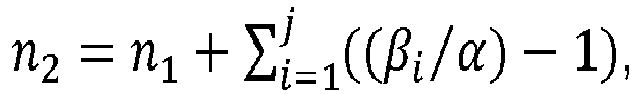
- α est le premier angle correspondant à une première distance angulaire séparant au moins deux repères de la graduation se suivant ;
- βi est le second angle, plus grand que le premier angle a, correspondant à une deuxième distance angulaire, différente de la première distance angulaire, séparant au moins deux autres repères de la graduation se suivant au niveau d'un secteur Si de la graduation ;
- i est un nombre entier compris entre 1 et j ;
- j est un nombre entier correspondant au nombre total de secteurs Si de la graduation où deux repères de la graduation se suivant sont espacés par un second angle βi plus grand que le premier angle α ;
- l'organe élastique est un ressort lame, une lamelle, un ressort plat, ou un ressort en spiral ;
- l'organe élastique est venu de matière avec la première roue de sorte qu'il comporte une première extrémité monobloc avec ladite première roue et une deuxième extrémité liée à la deuxième roue, ou l'organe élastique est venu de matière avec la deuxième roue de sorte qu'il comporte une première extrémité monobloc avec ladite deuxième roue et une deuxième extrémité liée à la première roue ;
- l'affichage comporte une graduation de quantième avec 31 repères et en ce que l'organe d'affichage est une aiguille de quantième ;
- la graduation de quantième comprend les chiffres 1 à 31 et/ou des indexes correspondant aux chiffres, les chiffres successifs de 1 à 31 étant séparés par le premier angle α et les
chiffres 31 et 1 étant séparé par le deuxième angle β plus grand que ledit premier angle α ; - la première roue comporte 31 dents et est configurée pour faire un tour en 31 jours, et le mécanisme d'affichage antérograde est configuré pour armer progressivement l'organe élastique pendant 31 jours ;
- l'affichage comporte une graduation des minutes ou des secondes avec 60 repères, et l'organe d'affichage est respectivement une aiguille de minutes ou de secondes.
- the first wheel is able to be driven by jumps by said clockwork movement;
- the first wheel has a number of teeth n 1 , the number of teeth n 1 being equal to the number of marks on the display scale;
- the second wheel has a number of teeth n 2 greater than the number of teeth n 1 of the first wheel;
- the third wheel has an effective number n 3 eff of teeth distributed over a toothed portion and a number of truncated teeth n 3 trunq on the smooth angular sector, the whole forming a number n 3 equivalence of teeth on the complete circumference of the third wheel, the number n 3 equivalence of teeth on the complete circumference of the third wheel being equal to the number of teeth n 2 of the second wheel;
- the number of truncated teeth n 3 trunq on the smooth angular sector of the third wheel is an integer corresponding to the ratio of the second angle β to the first angle α;
- the fourth wheel has a number of teeth n 4 equal to the number of teeth n 2 of the second wheel;
- the number of teeth n 2 of the second wheel is determined by the following relationship:
- α is the first angle corresponding to a first angular distance separating at least two marks of the following graduation;
- β i is the second angle, larger than the first angle a, corresponding to a second angular distance, different from the first angular distance, separating at least two other marks of the graduation following each other at the level of a sector S i of the graduation;
- i is an integer between 1 and j;
- j is an integer corresponding to the total number of sectors S i of the graduation where two marks of the graduation following one another are spaced by a second angle β i greater than the first angle α;
- the elastic member is a leaf spring, a lamella, a flat spring, or a spiral spring;
- the elastic member is integral with the first wheel so that it has a first end in one piece with said first wheel and a second end linked to the second wheel, or the elastic member is integral with the second wheel so that it comprises a first end in one piece with said second wheel and a second end linked to the first wheel;
- the display includes a date graduation with 31 marks and in that the display member is a date hand;
- the date graduation comprises the digits 1 to 31 and/or indexes corresponding to the digits, the successive digits from 1 to 31 being separated by the first angle α and the
digits 31 and 1 being separated by the second angle β greater than said first angle α; - the first wheel has 31 teeth and is configured to make one revolution in 31 days, and the anterograde display mechanism is configured to gradually arm the elastic member for 31 days;
- the display includes a minute or second graduation with 60 marks, and the display member is respectively a minute or second hand.
L'invention concerne également un mouvement d'horlogerie caractérisé en ce qu'il comporte un mécanisme d'affichage antérograde selon l'invention.The invention also relates to a clock movement characterized in that it comprises an anterograde display mechanism according to the invention.
L'invention concerne également une pièce d'horlogerie comportant un mouvement d'horlogerie mettant en mouvement un mécanisme d'affichage antérograde selon l'invention.The invention also relates to a timepiece comprising a timepiece movement setting in motion an anterograde display mechanism according to the invention.
Préférentiellement, la pièce d'horlogerie est une montre bracelet.Preferably, the timepiece is a wristwatch.
Les buts, avantages et caractéristiques de la présente invention apparaîtront à la lecture de la description détaillée ci-dessous faisant référence aux figures suivantes :
- la
figure 1 est une représentation schématique en perspective d'un premier exemple de réalisation d'un mécanisme d'affichage antérograde selon l'invention ; - la
figure 2 est une représentation schématique en vue de dessous du mécanisme d'affichage antérograde illustré à lafigure 1 ; - les
figures 3 à 6 illustrent schématiquement différentes positions du mécanisme d'affichage antérograde illustré à lafigure 1 ; - les
figures 7a et 7b illustrent schématiquement un deuxième exemple de réalisation du mécanisme d'affichage antérograde selon l'invention, et plus particulièrement un deuxième exemple de réalisation d'un cadran d'affichage à lafigure 7a et un deuxième exemple de réalisation d'une roue d'affichage correspondante, à lafigure 7b ; - les
figures 8a et 8b illustrent schématiquement un troisième exemple de réalisation du mécanisme d'affichage antérograde selon l'invention, et plus particulièrement un troisième exemple de réalisation d'un cadran d'affichage à lafigure 8a et un troisième exemple de réalisation d'une roue d'affichage correspondante, à lafigure 8b ; - les
figures 9a et 9b illustrent schématiquement un quatrième exemple de réalisation du mécanisme d'affichage antérograde selon l'invention, et plus particulièrement un quatrième exemple de réalisation d'un cadran d'affichage à lafigure 9a et un quatrième exemple de réalisation d'une roue d'affichage correspondante, à lafigure 9b .
- there
figure 1 is a schematic perspective representation of a first embodiment of an anterograde display mechanism according to the invention; - there
figure 2 is a schematic bottom view of the anterograde display mechanism shown infigure 1 ; - THE
figures 3 to 6 schematically illustrate different positions of the anterograde display mechanism illustrated infigure 1 ; - THE
figures 7a and 7b schematically illustrate a second embodiment of the anterograde display mechanism according to the invention, and more particularly a second example of embodiment of a display dial at thefigure 7a and a second embodiment of a corresponding display wheel, at thefigure 7b ; - THE
figures 8a and 8b schematically illustrate a third embodiment of the display mechanism anterograde according to the invention, and more particularly a third example of production of a display dial at thefigure 8a and a third embodiment of a corresponding display wheel, at thefigure 8b ; - THE
figures 9a and 9b schematically illustrate a fourth embodiment of the anterograde display mechanism according to the invention, and more particularly a fourth embodiment of a display dial at thefigure 9a and a fourth embodiment of a corresponding display wheel, at thefigure 9b .
Dans toutes les figures, les éléments communs portent les mêmes numéros de référence sauf précision contraire.In all figures, common elements bear the same reference numbers unless otherwise specified.
Le mécanisme d'affichage antérograde 100 selon l'invention est destiné à être logé dans une pièce d'horlogerie, par exemple dans une montre bracelet.The
Le mécanisme d'affichage antérograde 100 selon l'invention est configuré pour être animé par un mouvement d'horlogerie (non représenté), c'est-à-dire par un mécanisme dont le fonctionnement dépend de la division du temps.The
Le mécanisme d'affichage antérograde 100 est configuré pour réaliser un affichage par saut d'un organe d'affichage (ou indicateur), par exemple une aiguille, en regard d'un affichage, par exemple un cadran, présentant une graduation périphérique formée par une pluralité de repères répartis sur une circonférence de l'affichage, la distance angulaire séparant deux de ces repères consécutifs correspondant à un second angle β plus grand qu'un premier angle α séparant deux des autres repères consécutifs de la graduation. La graduation comporte au moins deux repères consécutifs séparés par un second angle β plus grand qu'un premier angle a.The
Dans une variante de réalisation (non représenté), le mécanisme d'affichage antérograde 100 est configuré pour réaliser un affichage par saut d'un organe d'affichage, par exemple un disque présentant une pluralité de repères, formant une graduation périphérique, répartis sur une circonférence du disque, coopérant avec une ouverture ménagée dans un cadran formant une fenêtre laissant apparaitre une portion de l'organe d'affichage.In a variant embodiment (not shown), the
Le mécanisme d'affichage antérograde 100 est configuré pour entrainer l'organe d'affichage par des sauts successifs courts entre les repères de la graduation séparés par le premier angle α et par un saut long entre les deux repères consécutifs de la graduation séparés par le second angle β.The
Dans un premier exemple de réalisation du mécanisme d'affichage antérograde 100 illustré particulièrement aux
Dans le premier exemple représenté aux
Dans l'exemple représenté, la graduation de quantième comprend les chiffres impairs 1 à 31 répartis sur une circonférence du cadran 3 ainsi que des indexes situés entre deux chiffres impairs. Les indexes situés entre les chiffres impairs représentent ici des chiffres pairs. Ils remplacent les chiffres de la graduation notamment pour une meilleure lisibilité de l'affichage. Ainsi, dans la présente de la demande, pour plus de clarté, on parlera uniquement de chiffre, les chiffres pairs étant ici des indexes.In the example shown, the date graduation includes the odd numbers 1 to 31 distributed over a circumference of the
La distance angulaire séparant les chiffres consécutifs 31 et 1 correspond à un second angle β plus grand qu'un premier angle α séparant les autres chiffres entre 1 et 31 de la graduation de quantième.The angular distance separating the
La
La
En référence aux
Dans l'exemple de réalisation représenté, la vitesse de rotation de la roue motrice 110 est de 1 tour en 31 jours, et la roue motrice est mise en mouvement une fois par jour par le mouvement d'horlogerie. La roue motrice 110 avance donc d'un pas par jour.In the embodiment shown, the rotation speed of the
A cet effet, la roue motrice 110 comporte un nombre de dents n 1 , ici égal à 31 dents pour 31 positions d'indexation de la roue motrice 110 correspondant à 31 positions indexées de l'organe d'affichage de quantième, vis-à-vis des 31 repères de la graduation de quantième du cadran 3.For this purpose, the
Chaque position d'indexation de la roue motrice 110 est indexée par un sautoir 180 coopérant avec la roue motrice 110. Le sautoir 180 est mobile en rotation autour d'un pivot 181 et contraint par un élément élastique (non représenté) tendant à ramener un bec de sautoir 182 vers l'axe de rotation de la roue motrice 110, de sorte que le bec de sautoir 182 coopère avec les dents et les espaces inter-dents de la roue motrice 110 pour garantir le maintien en position d'indexation de la roue motrice 110 entre chaque pas.Each indexing position of the
Le mécanisme d'affichage antérograde 100 comporte en outre une deuxième roue 120 montée coaxiale avec la roue motrice 110. La deuxième roue 120 comporte un nombre de dents n 2 différent du nombre de dents n 1 de la roue motrice 110. Avantageusement, la deuxième roue 120 comporte un nombre de dents n 2 supérieur au nombre de dents n 1 de la roue motrice 110.The
La roue matrice 110 et la deuxième roue 120 ne sont pas solidaires en rotation. Les deux roues 110, 120 sont liées l'une à l'autre par un organe élastique 160. L'organe élastique 160 comporte une première extrémité 161 solidaire de la roue motrice 110 et une deuxième extrémité 162 solidaire de la deuxième roue 120.The
On entend par solidaire une liaison mécanique dont au moins un degré de liberté est bloqué.By solidary we mean a mechanical connection of which at least one degree of freedom is blocked.
Le mécanisme d'affichage antérograde 100 comporte en outre une troisième roue 130, dite roue d'affichage, qui entraine l'organe d'affichage permettant d'afficher le quantième sur un cadran 3.The
Par exemple, comme représenté aux
Selon une variante de réalisation (non représentée), l'organe d'affichage est un disque solidaire en rotation de la roue d'affichage 130, le disque présentant une pluralité de repères formant la graduation de quantième, et étant configuré pour coopérer avec une ouverture du cadran pour laisser apparaitre une portion du disque.According to an alternative embodiment (not shown), the display member is a disk integral in rotation with the
La roue motrice 110 entraine en direct une roue intermédiaire 150, qui entraine en direct la roue d'affichage 130. La roue intermédiaire 150 permet avantageusement de réaliser un renvoi entre la roue motrice 110 et la roue d'affichage 130.The
La roue d'affichage 130 comporte au moins une portion dentée et au moins un secteur angulaire 131 dans lequel une pluralité de dents sont tronquées de manière à former un secteur angulaire « lisse » sans dent. Ainsi, momentanément, à chaque rotation complète de la roue d'affichage 130, la roue d'affichage 130 n'est plus directement en prise avec la roue motrice 110 lorsque le secteur angulaire lisse 131 de la roue d'affichage 130 se retrouvera en regard de la denture de la roue intermédiaire 150.The
Dans le cas particulier illustré aux
Dans l'exemple représenté aux
Ainsi, la roue d'affichage 130 comporte un nombre effectif n 3 eff de dents réparties sur la portion dentée et un nombre n 3 tronq de dents tronquées sur le secteur angulaire lisse 131. On obtient ainsi un nombre n 3 equi correspondant à une équivalence de dents sur la circonférence de la roue.Thus, the
Pour la roue d'affichage 130, nous avons la relation suivante : ![]()
![]()
On notera que la roue d'affichage 130 peut également comprendre plusieurs portions dentées et plusieurs secteurs angulaires lisses 131, présentant une distance angulaire plus ou moins importante, une distance angulaire égale ou non, qui peuvent être répartis uniformément, ou non, sur la circonférence de la roue d'affichage 130, en fonction des besoins. D'autres exemples de réalisation seront décrits par la suite en référence aux
Le mécanisme d'affichage antérograde 100 comporte en outre une quatrième roue 140 coaxiale avec la roue d'affichage 130 et solidaire en rotation avec la roue avec la roue d'affichage 130. La quatrième roue comporte un nombre de dents n 4.The
La quatrième roue 140 engrène directement avec une deuxième roue intermédiaire 170 qui engrène directement avec la deuxième roue 120, de sorte que la deuxième roue 120 est entrainée en rotation par la deuxième roue intermédiaire 170.The
Avantageusement, la deuxième roue 120 présente un nombre de dents n 2 supérieur au nombre de dents n 1 de la roue motrice 110, de manière à avoir une vitesse de rotation inférieure à la vitesse de rotation de la roue motrice 110, et ainsi armer, ou charger, progressivement l'organe élastique 160 lors de la rotation de la roue motrice 110.Advantageously, the
Avantageusement, la deuxième roue 120 et la roue d'affichage 130 présentent respectivement un nombre de dents n 2, n3 equi supérieur au nombre de dents n 1 de la roue motrice 110. Avantageusement, la deuxième roue 120 et la roue d'affichage 130 présentent le même nombre de dents (n 2 = n 3 equi ). Advantageously, the
Avantageusement, la deuxième roue 120, la roue d'affichage 130, et la quatrième roue 140 présentent respectivement un nombre de dents n 2, n 3 equi , n 4 supérieur au nombre de dents n 1 de la roue motrice 110. Avantageusement la deuxième roue 120, la roue d'affichage 130, et la quatrième roue 140 présentent le même nombre de dents (n 2 = n 3 equi = n 4).Advantageously, the
Dans l'exemple de réalisation illustré aux
Dans cet exemple, l'angle β est deux fois plus grand que l'angle α.In this example, angle β is twice as large as angle α.
Ainsi, le cadran 3 est divisée en 32 divisions équidistantes, dont deux divisions consécutives sont séparées par le premier angle α.Thus, dial 3 is divided into 32 equidistant divisions, two consecutive divisions of which are separated by the first angle α.
Ces divisions forment des positions indexables Px, avec x allant de 1 à 32.These divisions form indexable positions P x , with x ranging from 1 to 32.
Les 31 chiffres formant les repères de la graduation de quantième sont répartis au niveau de 31 positions indexables du cadran 3, les positions P1 à P31.The 31 digits forming the markers of the date graduation are distributed at the level of 31 indexable positions of the
La position indexable P32 (fictive, représentée en conséquence en pointillés) ne présente pas de repère et est destinée à être directement sautée par l'aiguille de quantième 2 faisant un saut long d'angle β entre le chiffre 31 (position indexable P31) et le chiffre 1 (position indexable P1).The indexable position P 32 (fictitious, represented accordingly in dotted lines) does not have a mark and is intended to be directly jumped by the
La roue motrice 110 comporte 31 dents correspondant aux 31 positions indexées de l'aiguille de quantième 2, et donc 31 repères du cadran 3 de la graduation de quantième.The
Avantageusement, la deuxième roue 120 comporte un nombre de dents n 2 défini par la relation suivante : ![]()
- α est un premier angle correspondant à une première distance angulaire séparant au moins deux repères de la graduation se suivant,
- βi est un second angle, plus grand que le premier angle a, correspondant à une deuxième distance angulaire, différente de la première distance angulaire, séparant au moins deux autres repères de la graduation se suivant au niveau d'un secteur Si de la graduation,
- i est un nombre entier compris entre 1 et j ;
- j est un nombre entier correspondant au nombre total de secteurs Si de la graduation où deux repères de la graduation se suivant sont espacés par un second angle βi plus grand que le premier angle α.
- α is a first angle corresponding to a first angular distance separating at least two marks of the following graduation,
- β i is a second angle, larger than the first angle a, corresponding to a second angular distance, different from the first angular distance, separating at least two other marks of the graduation following each other at the level of a sector S i of the graduation,
- i is an integer between 1 and j;
- j is an integer corresponding to the total number of sectors S i of the graduation where two marks of the graduation following each other are spaced by a second angle β i greater than the first angle α.
Comme vu précédemment, le second angle β est deux fois plus grand que le premier angle α. ![]()
![]()
![]()
![]()
![]()
![]()
Le nombre n 3 tronq de dents tronquées au niveau du secteur angulaire lisse 131 de la roue d'affichage 130 est équivalent au rapport entre le second angle β et le premier angle α. ![]()
![]()
Ainsi, dans l'exemple de réalisation représenté aux
Pour une rotation complète de la roue motrice 110, la deuxième roue 120 présentera un retard angulaire de 1/32° par rapport à la roue motrice 110 qui fait un tour en 31 jours. La différence de vitesse de rotation relative entre la roue motrice 110 et la deuxième roue 120 va charger, ou armer, progressivement l'organe élastique 160, par déformation élastique, tout au long d'une période donnée, ici 31 jours.For a complete rotation of the
L'organe élastique 160 peut être un ressort lame, une lamelle, un ressort plat, un ressort en spiral ou tout autre élément élastique classiquement utilisé dans le domaine de l'horlogerie.The
Dans l'exemple de réalisation illustré aux
A titre d'exemple, la deuxième extrémité 162 forme une tête d'accroché comportant une goupille 163 coopérant avec une ganse oblongue 121 ménagée sur la deuxième roue 120 pour solidariser en rotation la deuxième extrémité 162 de l'organe élastique 160 à la deuxième roue 120.For example, the
Selon une variante de réalisation non représentée, l'organe élastique est venu de matière avec la deuxième roue 120, de sorte que la deuxième extrémité 162 est monobloc avec la deuxième roue 120 et que la première extrémité 161 est liée sur la roue motrice 110.According to an alternative embodiment not shown, the elastic member is integral with the
Le fonctionnement du mécanisme d'affichage antérograde 100 selon l'invention va être décrit par la suite en référence aux
La
A partir de cette position initiale du mécanisme d'affichage antérograde 100, la roue d'affichage 130 est entrainée par la roue motrice 110 pendant 31 jours, à chaque pas de la roue motrice 110. Pendant cette période de 31 jours, l'aiguille de quantième 2 est déplacée angulairement une fois par jour par sauts successifs courts d'angle α. L'aiguille de quantième 2 est donc indexée jour après jour au niveau des différents repères de la graduation de quantième correspondant aux différentes divisions, ou positions indexables Px, du cadran 3 séparées d'un angle α ; c'est-à-dire entre les chiffre 1 et le chiffre 31, jusqu'à arriver au chiffre 31 de la graduation de quantième du cadran 3 (position P31), comme illustré à la
Durant cette période de 31 jours, le rapport d'engrenage entre la roue motrice 110 et les autres roues 120, 130, 140 du mécanisme engendre un décalage angulaire entre la roue motrice 110 et la deuxième roue 120. Ce décalage, augmentant à chaque incrémentation par la roue motrice 110, va charger progressivement l'organe élastique 160.During this period of 31 days, the gear ratio between the
Lorsque l'aiguille de quantième 2 est indexée sur la position P31 du cadran 3 (chiffre 31 de la graduation de quantième), la différence angulaire relative entre la roue motrice 110 et la deuxième roue 120 est maximale, et l'organe élastique 160 est dans sa position armée maximale.When the
A l'opposé, comme illustré à la
Après l'indexage de l'organe d'affichage sur la position indexable P31, illustré à la
Sous la décharge de l'organe élastique 160, la deuxième roue 120 tend à rattraper son retard angulaire accumulée pendant les 31 jours précédents, par rapport à la roue motrice 110, et entraine en rotation la roue d'affichage 130 (dans le même sens de rotation que la roue motrice 110) de manière à faire avancer l'aiguille de quantième 2 en avant (dans le sens de marche des aiguilles d'une montre) jusqu'au passage du secteur angulaire lisse 131 et jusqu'à ce que la roue intermédiaire 150 entre en contact avec la dent d1 bordant le secteur angulaire lisse 131, comme illustré à la
Le déchargement de l'organe élastique intervient instantanément alors que la roue motrice 110 n'a pas encore complété sa rotation correspondant au pas angulaire journalier. Cette phase est notamment illustrée par la
En effet, à ce stade, le pas de la roue motrice 110 n'est pas encore complet car le sautoir 180 n'est pas encore positionné entre deux dents de la roue motrice 110. Avec la force de rappel de l'élément élastique agissant sur le sautoir 180, le sautoir 180 tend à finaliser la rotation de la roue motrice 110 jusqu'à la position d'indexation suivante. La rotation supplémentaire de la roue motrice 110 sous l'effet du sautoir 180 va permettre de décaler la première roue intermédiaire 150 et donc la roue d'affichage 130 pour finaliser le saut de l'aiguille de quantième 2 et amener l'aiguille de quantième 2 en regard du chiffre 1 de la graduation de quantième du cadran 3, comme illustré à la
Ainsi, le saut long d'angle β de l'aiguille de quantième 2 entre le chiffre 31 et le chiffre 1 de la graduation de quantième correspond à la rotation d'angle α classiquement généré par le pas journalier de la roue motrice 110 et par le déchargement de l'organe élastique 160 occasionnant un rotation supplémentaire d'un angle ε = β - α pour atteindre directement le chiffre 1 de la graduation de quantième.Thus, the long jump of angle β of the
Bien entendu la rotation de la roue d'affichage 130 et donc de l'aiguille de quantième 2 due à la décharge de l'organe élastique 160 dépend de l'énergie accumulée durant la précédente période d'indexation et de la distance angulaire du secteur angulaire lisse 131 de la roue d'affichage 130. Ainsi, différentes configurations sont possibles, et le saut long d'angle β peut être supérieure à deux fois l'angle α.Of course the rotation of the
Les
Dans ce deuxième exemple de réalisation, le cadran 3 est divisé en 35 divisions équidistantes, dont deux divisions consécutives sont séparées par le premier angle α.In this second embodiment, dial 3 is divided into 35 equidistant divisions, two consecutive divisions of which are separated by the first angle α.
Ces divisions forment des positions indexables Px, avec x allant de 1 à 35.These divisions form indexable positions P x , with x ranging from 1 to 35.
Les 31 chiffres formant les repères de la graduation de quantième sont répartis au niveau de 31 positions indexables Px du cadran 3, les positions P1 à P15 et les positions P16 à P35.The 31 digits forming the markers of the date graduation are distributed at 31 indexable positions P x of
Dans cet exemple de réalisation, quatre divisions ou positions indexables successives du cadran 3, ici les positions P16 à P19 sont fictives et ne présentent pas de repère de quantième. Par conséquent, ces divisions ne sont pas destinées à être indexées par l'aiguille de quantième 2.In this exemplary embodiment, four successive divisions or indexable positions of
En effet, entre le chiffre 15 et le chiffre 16, l'aiguille de quantième 2 fait ici un saut long d'angle β, passant du chiffre 15 (position indexable P15) au chiffre 16 (position indexable P20), cinq fois plus grand que l'angle α entre les autres chiffres de la graduation de quantième.Indeed, between the
La roue motrice 110 comporte 31 dents correspondant aux 31 positions indexées de l'aiguille de quantième 2, et donc 31 repères du cadran 3 de la graduation de quantième.The
La deuxième roue 120 comporte un nombre de dents n 2 défini par la relation suivante : ![]()
![]()
![]()
![]()
Ainsi, dans ce deuxième exemple de réalisation, la deuxième roue 120 et la quatrième roue présentent 35 dents, et la roue d'affichage 130 est équivalente à une roue de 35 dents.Thus, in this second embodiment, the
Le nombre de dents tronquées n 3 tronq au niveau du secteur angulaire lisse 131 de la roue d'affichage 130 est égal à 5 : ![]()
![]()
Par conséquent, dans ce deuxième exemple de réalisation, la roue d'affichage 130 est équivalente à une roue de 35 dents sur laquelle cinq dents consécutives sont tronquées au niveau du secteur angulaire lisse 131. La roue d'affichage 130 présente donc 30 dents effectives.Consequently, in this second embodiment, the
Les
Dans ce troisième exemple de réalisation, le cadran 3 est divisé en 66 divisions équidistantes, dont deux divisions consécutives sont séparées par le premier angle α.In this third embodiment, dial 3 is divided into 66 equidistant divisions, two consecutive divisions of which are separated by the first angle α.
Ces divisions forment des positions indexables Px, avec x allant de 1 à 66.These divisions form indexable positions P x , with x ranging from 1 to 66.
Dans ce troisième exemple de réalisation, les 60 repères de la graduation des minutes sont répartis sur 60 positions indexables Px du cadran 3, les positions P1 à P30, et les positions P34 à P63.In this third embodiment, the 60 marks of the minute graduation are distributed over 60 indexable positions P x of
La cadran 3 comportent deux secteurs S1 et S2 comportant trois divisons successives, ici les positions P31 à P33 et P64 à P66, qui sont fictives et ne présentent pas de repère de minute. Par conséquent, ces divisions ne sont pas destinées à être indexées par l'aiguille des minutes.
Ainsi, au niveau du premier secteur S1, entre le chiffre 30 et le chiffre 31, l'aiguille des minutes fait ici un premier saut long d'un angle β1, quatre fois plus grand que l'angle α correspondant au saut court entre les chiffres de la graduation des minutes.Thus, at the level of the first sector S 1 , between the
Au niveau du deuxième secteur S2, entre le chiffre 60 et le chiffre 1, l'aiguille des minutes fait ici un deuxième saut long d'un angle β2, quatre fois plus grand que l'angle α correspondant au saut court entre les chiffres de la graduation des minutes.At the level of the second sector S 2 , between the number 60 and the number 1, the minute hand here makes a second long jump of an angle β 2 , four times greater than the angle α corresponding to the short jump between the digits of the minute scale.
Dans cet exemple de réalisation, la roue motrice comporte 60 dents pour les 60 minutes indexées par l'organe d'affichage des minutes.In this embodiment, the drive wheel has 60 teeth for the 60 minutes indexed by the minute display member.
La deuxième roue 120 comporte un nombre de dents n 2 défini par la relation suivante : ![]()
![]()
![]()
![]()
![]()
![]()
Ainsi, dans ce troisième exemple de réalisation la deuxième roue 120 et la quatrième roue présentent 66 dents, et la roue d'affichage 130 est équivalente à une roue de 66 dents.Thus, in this third embodiment the
La roue d'affichage 130, illustrée à la
Le nombre n3 tronq de dents tronquées au niveau du premier secteur angulaire lisse 131a de la roue d'affichage 130 est égal à 4 : ![]()
![]()
Le nombre n'3 tronq de dents tronquées au niveau du deuxième secteur angulaire lisse 131b de la roue d'affichage 130 est égal à 4 : ![]()
![]()
Par conséquent, dans ce troisième exemple de réalisation, la roue d'affichage 130 est équivalente à une roue de 66 dents sur laquelle quatre dents consécutives sont tronquées au niveau d'un premier secteur angulaire lisse 131a et quatre dents consécutives sont tronquées au niveau d'un second secteur angulaire lisse 131b.Consequently, in this third embodiment, the
La roue d'affichage 130 présente donc 58 dents effectives, soit 29 dents consécutives entre chaque secteur angulaire lisse 131a, 131b, soit 29 dents consécutives sur une première portion dentée et un 29 dents consécutives sur une deuxième portion dentée.The
Les
Dans ce quatrième exemple de réalisation, le cadran 3 est divisé en 68 divisions équidistantes, dont deux divisions consécutives sont séparées par le premier angle α.In this fourth embodiment, dial 3 is divided into 68 equidistant divisions, two consecutive divisions of which are separated by the first angle α.
Ces divisions forment des positions indexables Px, avec x allant de 1 à 68.These divisions form indexable positions P x , with x ranging from 1 to 68.
Dans ce quatrième exemple de réalisation, les 60 repères de la graduation des minutes sont répartis sur 60 positions indexables Px.In this fourth embodiment, the 60 marks of the minute graduation are distributed over 60 indexable positions P x .
Le cadran 3 comporte quatre secteurs S1, S2, S3 et S4 de deux divisions successives, ici les positions P16, P17, P33, P34, P50, P51, P67, P68, qui sont fictives et ne présentent pas de repère de minute. Par conséquent, ces divisions ne sont pas destinées à être indexées par l'aiguille des minutes.The
Ainsi, au niveau du premier secteur S1, entre le chiffre 15 et le chiffre 16, l'aiguille des minutes fait ici un premier saut long d'un angle β1, trois fois plus grand que l'angle α correspondant au saut court entre les chiffres de la graduation des minutes.Thus, at the level of the first sector S 1 , between the
Au niveau du deuxième secteur S2, entre le chiffre 30 et le chiffre 31, l'aiguille des minutes fait ici un deuxième saut long d'un angle β2, trois fois plus grand que l'angle α correspondant au saut court entre les chiffres de la graduation des minutes.At the level of the second sector S 2 , between the
Au niveau du troisième secteur S3, entre le chiffre 45 et le chiffre 46, l'aiguille des minutes fait ici un troisième saut long d'un angle β3, trois fois plus grand que l'angle α correspondant au saut court entre les chiffres de la graduation des minutes.At the level of the third sector S 3 , between the number 45 and the number 46, the minute hand here makes a third long jump of an angle β 3 , three times greater than the angle α corresponding to the short jump between the digits of the minute scale.
Au niveau du quatrième secteur S4, entre le chiffre 60 et le chiffre 1, l'aiguille des minutes fait ici un quatrième saut long d'un angle β4, trois fois plus grand que l'angle α correspondant au saut court entre les chiffres de la graduation des minutes.At the level of the fourth sector S 4 , between the number 60 and the number 1, the minute hand here makes a fourth long jump of an angle β 4 , three times greater than the angle α corresponding to the short jump between the digits of the minute scale.
Dans cet exemple de réalisation, la roue motrice comporte 60 dents pour les 60 minutes indexées par l'organe d'affichage des minutes.In this embodiment, the drive wheel has 60 teeth for the 60 minutes indexed by the minute display member.
La deuxième roue 120 comporte un nombre de dents n 2 défini par la relation suivante : ![]()
![]()
![]()
![]()
![]()
![]()
Ainsi, la deuxième roue 120 et la quatrième roue présentent 68 dents, et la roue d'affichage 130 est équivalente à une roue de 68 dents.Thus, the
La roue d'affichage 130, illustrée à la
Le nombre de dents tronquées n 3 tronq au niveau du premier secteur angulaire lisse 131a de la roue d'affichage 130 est égal à 3 : ![]()
![]()
Le nombre de dents tronquées n' 3 tronq au niveau du deuxième secteur angulaire lisse 131b de la roue d'affichage 130 est égal à 3 : ![]()
![]()
Le nombre de dents tronquées n" 3 tronq au niveau du troisième secteur angulaire lisse 131c de la roue d'affichage 130 est égal à 3 : ![]()
![]()
Le nombre de dents tronquées n‴ 3 tronq au niveau du quatrième secteur angulaire lisse 131d de la roue d'affichage 130 est égal à 3 : ![]()
![]()
Par conséquent, dans ce quatrième exemple de réalisation, la roue d'affichage 130 est équivalente à une roue de 68 dents sur laquelle deux dents consécutives sont tronquées au niveau de quatre secteurs angulaires lisses 131a, 131b, 131c, 131d.Consequently, in this fourth embodiment, the
La roue d'affichage 130 présente donc 56 dents effectives, soit 14 dents consécutives entre chaque secteur angulaire lisse 131a, 131b, 131c, 131d. Ainsi, la roue d'affichage 130 comporte une première portion dentée de 14 dents, une deuxième portion dentée de 14 dents, une troisième portion dentée de 14 dents et une quatrième portion dentée de 14 dents, chacune des portions dentées étant séparées par un secteur angulaire lisse 131a, 131b, 131c, 131d correspondant à un secteur angulaire équivalent à trois dents.The
L'invention concerne également un mouvement d'horlogerie comportant un tel mécanisme d'affichage antérograde.The invention also relates to a watch movement comprising such an anterograde display mechanism.
L'invention concerne également une pièce d'horlogerie, telle qu'une montre bracelet comportant un tel mouvement horloger.The invention also relates to a timepiece, such as a wristwatch comprising such a watch movement.
Claims (16)
Priority Applications (4)
| Application Number | Priority Date | Filing Date | Title |
|---|---|---|---|
| EP22173340.5A EP4276545A1 (en) | 2022-05-13 | 2022-05-13 | Anterograde display device for a timepiece |
| US18/173,942 US20230367264A1 (en) | 2022-05-13 | 2023-02-24 | Anterograde display mechanism for timepiece |
| JP2023049307A JP7472350B2 (en) | 2022-05-13 | 2023-03-27 | Prograde display mechanism for a timepiece. |
| CN202310427394.8A CN117055320A (en) | 2022-05-13 | 2023-04-20 | Forward motion display mechanism for timepiece |
Applications Claiming Priority (1)
| Application Number | Priority Date | Filing Date | Title |
|---|---|---|---|
| EP22173340.5A EP4276545A1 (en) | 2022-05-13 | 2022-05-13 | Anterograde display device for a timepiece |
Publications (1)
| Publication Number | Publication Date |
|---|---|
| EP4276545A1 true EP4276545A1 (en) | 2023-11-15 |
Family
ID=81653588
Family Applications (1)
| Application Number | Title | Priority Date | Filing Date |
|---|---|---|---|
| EP22173340.5A Pending EP4276545A1 (en) | 2022-05-13 | 2022-05-13 | Anterograde display device for a timepiece |
Country Status (3)
| Country | Link |
|---|---|
| US (1) | US20230367264A1 (en) |
| EP (1) | EP4276545A1 (en) |
| CN (1) | CN117055320A (en) |
Citations (4)
| Publication number | Priority date | Publication date | Assignee | Title |
|---|---|---|---|---|
| CH699736B1 (en) | 2006-03-24 | 2010-04-30 | Richemont Int Sa | A central calendar. |
| CH707439A2 (en) * | 2013-01-11 | 2014-07-15 | Patek Philippe Sa Geneve | Display mechanism for displaying number of weeks in clockwork movement of timepiece, has indicating hand performing jump relative to minutes gradation corresponding to angular distance of toothless sector of wheel connected to another wheel |
| CH713209A2 (en) | 2016-12-08 | 2018-06-15 | Richemont Int Sa | Display mechanism for a timepiece. |
| CH715723A1 (en) * | 2019-01-10 | 2020-07-15 | Richemont Int Sa | Instant jump mechanism of a display mobile. |
-
2022
- 2022-05-13 EP EP22173340.5A patent/EP4276545A1/en active Pending
-
2023
- 2023-02-24 US US18/173,942 patent/US20230367264A1/en active Pending
- 2023-04-20 CN CN202310427394.8A patent/CN117055320A/en active Pending
Patent Citations (4)
| Publication number | Priority date | Publication date | Assignee | Title |
|---|---|---|---|---|
| CH699736B1 (en) | 2006-03-24 | 2010-04-30 | Richemont Int Sa | A central calendar. |
| CH707439A2 (en) * | 2013-01-11 | 2014-07-15 | Patek Philippe Sa Geneve | Display mechanism for displaying number of weeks in clockwork movement of timepiece, has indicating hand performing jump relative to minutes gradation corresponding to angular distance of toothless sector of wheel connected to another wheel |
| CH713209A2 (en) | 2016-12-08 | 2018-06-15 | Richemont Int Sa | Display mechanism for a timepiece. |
| CH715723A1 (en) * | 2019-01-10 | 2020-07-15 | Richemont Int Sa | Instant jump mechanism of a display mobile. |
Also Published As
| Publication number | Publication date |
|---|---|
| US20230367264A1 (en) | 2023-11-16 |
| JP2023168233A (en) | 2023-11-24 |
| CN117055320A (en) | 2023-11-14 |
Similar Documents
| Publication | Publication Date | Title |
|---|---|---|
| EP0940833B1 (en) | Calendar mechanism for watch movement | |
| EP1586962B1 (en) | Ewiger Kalendermechanismus | |
| EP2428856B1 (en) | Timepiece | |
| EP1546818B1 (en) | Mechanical hour and minute display device | |
| EP1916575B1 (en) | Annual calendar mechanism for timepiece | |
| CH712219A2 (en) | Mechanism for watch movement with retrograde and jumping display. | |
| EP0987609B1 (en) | Annual calendar mechanism for clockwork-movement | |
| EP3152626B1 (en) | Electronic clock movement comprising an analog display of several items of information | |
| EP3904964B1 (en) | Device for displaying a time or time-derived indication and device for indexing | |
| EP3690556B1 (en) | Timepiece comprising a display with variable pitch | |
| EP4276545A1 (en) | Anterograde display device for a timepiece | |
| EP1158374B1 (en) | Calendar display mechanism | |
| CH719692A2 (en) | Anterograde display mechanism for timepiece. | |
| CH703247B1 (en) | acoustic indicator of reserve of a timepiece. | |
| EP3765922B1 (en) | Clock piece | |
| EP1351105A1 (en) | Timepiece with perpetual calender display | |
| CH711184B1 (en) | Watch movement comprising a mechanism for rapid correction of the current time. | |
| EP3786723A1 (en) | Display mechanism | |
| EP3904962B1 (en) | Device for indexing and device for displaying a time or time-derived indication | |
| EP3857313B1 (en) | Display mechanism with a single dial window | |
| EP3629101B1 (en) | Timepiece display mechanism | |
| WO2006108878A1 (en) | Jumping hour display mechanism for timepiece | |
| EP3667435B1 (en) | System for adjusting the position of a first toothed moving part relative to a support on which the first toothed moving part is pivotably mounted, and timepiece comprising such a system | |
| WO2002084413A1 (en) | Calendar date mechanism | |
| EP4254079A1 (en) | Mechanism for displaying the phases of the moon for a timepiece |
Legal Events
| Date | Code | Title | Description |
|---|---|---|---|
| PUAI | Public reference made under article 153(3) epc to a published international application that has entered the european phase |
Free format text: ORIGINAL CODE: 0009012 |
|
| STAA | Information on the status of an ep patent application or granted ep patent |
Free format text: STATUS: THE APPLICATION HAS BEEN PUBLISHED |
|
| AK | Designated contracting states |
Kind code of ref document: A1 Designated state(s): AL AT BE BG CH CY CZ DE DK EE ES FI FR GB GR HR HU IE IS IT LI LT LU LV MC MK MT NL NO PL PT RO RS SE SI SK SM TR |