EP4276348B1 - Ventil für eine gaskartusche, gaskartusche für einen wassersprudler und verfahren zum befüllen einer solchen gaskartusche - Google Patents
Ventil für eine gaskartusche, gaskartusche für einen wassersprudler und verfahren zum befüllen einer solchen gaskartusche Download PDFInfo
- Publication number
- EP4276348B1 EP4276348B1 EP23172061.6A EP23172061A EP4276348B1 EP 4276348 B1 EP4276348 B1 EP 4276348B1 EP 23172061 A EP23172061 A EP 23172061A EP 4276348 B1 EP4276348 B1 EP 4276348B1
- Authority
- EP
- European Patent Office
- Prior art keywords
- gas
- valve
- cartridge
- opening
- outlet
- Prior art date
- Legal status (The legal status is an assumption and is not a legal conclusion. Google has not performed a legal analysis and makes no representation as to the accuracy of the status listed.)
- Active
Links
Images
Classifications
-
- F—MECHANICAL ENGINEERING; LIGHTING; HEATING; WEAPONS; BLASTING
- F17—STORING OR DISTRIBUTING GASES OR LIQUIDS
- F17C—VESSELS FOR CONTAINING OR STORING COMPRESSED, LIQUEFIED OR SOLIDIFIED GASES; FIXED-CAPACITY GAS-HOLDERS; FILLING VESSELS WITH, OR DISCHARGING FROM VESSELS, COMPRESSED, LIQUEFIED, OR SOLIDIFIED GASES
- F17C13/00—Details of vessels or of the filling or discharging of vessels
- F17C13/04—Arrangement or mounting of valves
-
- F—MECHANICAL ENGINEERING; LIGHTING; HEATING; WEAPONS; BLASTING
- F17—STORING OR DISTRIBUTING GASES OR LIQUIDS
- F17C—VESSELS FOR CONTAINING OR STORING COMPRESSED, LIQUEFIED OR SOLIDIFIED GASES; FIXED-CAPACITY GAS-HOLDERS; FILLING VESSELS WITH, OR DISCHARGING FROM VESSELS, COMPRESSED, LIQUEFIED, OR SOLIDIFIED GASES
- F17C2201/00—Vessel construction, in particular geometry, arrangement or size
- F17C2201/01—Shape
- F17C2201/0104—Shape cylindrical
- F17C2201/0109—Shape cylindrical with exteriorly curved end-piece
-
- F—MECHANICAL ENGINEERING; LIGHTING; HEATING; WEAPONS; BLASTING
- F17—STORING OR DISTRIBUTING GASES OR LIQUIDS
- F17C—VESSELS FOR CONTAINING OR STORING COMPRESSED, LIQUEFIED OR SOLIDIFIED GASES; FIXED-CAPACITY GAS-HOLDERS; FILLING VESSELS WITH, OR DISCHARGING FROM VESSELS, COMPRESSED, LIQUEFIED, OR SOLIDIFIED GASES
- F17C2201/00—Vessel construction, in particular geometry, arrangement or size
- F17C2201/05—Size
- F17C2201/058—Size portable (<30 l)
-
- F—MECHANICAL ENGINEERING; LIGHTING; HEATING; WEAPONS; BLASTING
- F17—STORING OR DISTRIBUTING GASES OR LIQUIDS
- F17C—VESSELS FOR CONTAINING OR STORING COMPRESSED, LIQUEFIED OR SOLIDIFIED GASES; FIXED-CAPACITY GAS-HOLDERS; FILLING VESSELS WITH, OR DISCHARGING FROM VESSELS, COMPRESSED, LIQUEFIED, OR SOLIDIFIED GASES
- F17C2205/00—Vessel construction, in particular mounting arrangements, attachments or identifications means
- F17C2205/03—Fluid connections, filters, valves, closure means or other attachments
- F17C2205/0302—Fittings, valves, filters, or components in connection with the gas storage device
- F17C2205/0311—Closure means
- F17C2205/0314—Closure means breakable, e.g. with burst discs
-
- F—MECHANICAL ENGINEERING; LIGHTING; HEATING; WEAPONS; BLASTING
- F17—STORING OR DISTRIBUTING GASES OR LIQUIDS
- F17C—VESSELS FOR CONTAINING OR STORING COMPRESSED, LIQUEFIED OR SOLIDIFIED GASES; FIXED-CAPACITY GAS-HOLDERS; FILLING VESSELS WITH, OR DISCHARGING FROM VESSELS, COMPRESSED, LIQUEFIED, OR SOLIDIFIED GASES
- F17C2205/00—Vessel construction, in particular mounting arrangements, attachments or identifications means
- F17C2205/03—Fluid connections, filters, valves, closure means or other attachments
- F17C2205/0302—Fittings, valves, filters, or components in connection with the gas storage device
- F17C2205/0323—Valves
- F17C2205/0329—Valves manually actuated
-
- F—MECHANICAL ENGINEERING; LIGHTING; HEATING; WEAPONS; BLASTING
- F17—STORING OR DISTRIBUTING GASES OR LIQUIDS
- F17C—VESSELS FOR CONTAINING OR STORING COMPRESSED, LIQUEFIED OR SOLIDIFIED GASES; FIXED-CAPACITY GAS-HOLDERS; FILLING VESSELS WITH, OR DISCHARGING FROM VESSELS, COMPRESSED, LIQUEFIED, OR SOLIDIFIED GASES
- F17C2205/00—Vessel construction, in particular mounting arrangements, attachments or identifications means
- F17C2205/03—Fluid connections, filters, valves, closure means or other attachments
- F17C2205/0302—Fittings, valves, filters, or components in connection with the gas storage device
- F17C2205/0382—Constructional details of valves, regulators
-
- F—MECHANICAL ENGINEERING; LIGHTING; HEATING; WEAPONS; BLASTING
- F17—STORING OR DISTRIBUTING GASES OR LIQUIDS
- F17C—VESSELS FOR CONTAINING OR STORING COMPRESSED, LIQUEFIED OR SOLIDIFIED GASES; FIXED-CAPACITY GAS-HOLDERS; FILLING VESSELS WITH, OR DISCHARGING FROM VESSELS, COMPRESSED, LIQUEFIED, OR SOLIDIFIED GASES
- F17C2205/00—Vessel construction, in particular mounting arrangements, attachments or identifications means
- F17C2205/03—Fluid connections, filters, valves, closure means or other attachments
- F17C2205/0388—Arrangement of valves, regulators, filters
- F17C2205/0394—Arrangement of valves, regulators, filters in direct contact with the pressure vessel
-
- F—MECHANICAL ENGINEERING; LIGHTING; HEATING; WEAPONS; BLASTING
- F17—STORING OR DISTRIBUTING GASES OR LIQUIDS
- F17C—VESSELS FOR CONTAINING OR STORING COMPRESSED, LIQUEFIED OR SOLIDIFIED GASES; FIXED-CAPACITY GAS-HOLDERS; FILLING VESSELS WITH, OR DISCHARGING FROM VESSELS, COMPRESSED, LIQUEFIED, OR SOLIDIFIED GASES
- F17C2221/00—Handled fluid, in particular type of fluid
- F17C2221/01—Pure fluids
- F17C2221/013—Carbon dioxide
-
- F—MECHANICAL ENGINEERING; LIGHTING; HEATING; WEAPONS; BLASTING
- F17—STORING OR DISTRIBUTING GASES OR LIQUIDS
- F17C—VESSELS FOR CONTAINING OR STORING COMPRESSED, LIQUEFIED OR SOLIDIFIED GASES; FIXED-CAPACITY GAS-HOLDERS; FILLING VESSELS WITH, OR DISCHARGING FROM VESSELS, COMPRESSED, LIQUEFIED, OR SOLIDIFIED GASES
- F17C2223/00—Handled fluid before transfer, i.e. state of fluid when stored in the vessel or before transfer from the vessel
- F17C2223/01—Handled fluid before transfer, i.e. state of fluid when stored in the vessel or before transfer from the vessel characterised by the phase
- F17C2223/0107—Single phase
- F17C2223/0123—Single phase gaseous, e.g. CNG, GNC
-
- F—MECHANICAL ENGINEERING; LIGHTING; HEATING; WEAPONS; BLASTING
- F17—STORING OR DISTRIBUTING GASES OR LIQUIDS
- F17C—VESSELS FOR CONTAINING OR STORING COMPRESSED, LIQUEFIED OR SOLIDIFIED GASES; FIXED-CAPACITY GAS-HOLDERS; FILLING VESSELS WITH, OR DISCHARGING FROM VESSELS, COMPRESSED, LIQUEFIED, OR SOLIDIFIED GASES
- F17C2223/00—Handled fluid before transfer, i.e. state of fluid when stored in the vessel or before transfer from the vessel
- F17C2223/03—Handled fluid before transfer, i.e. state of fluid when stored in the vessel or before transfer from the vessel characterised by the pressure level
- F17C2223/036—Very high pressure (>80 bar)
-
- F—MECHANICAL ENGINEERING; LIGHTING; HEATING; WEAPONS; BLASTING
- F17—STORING OR DISTRIBUTING GASES OR LIQUIDS
- F17C—VESSELS FOR CONTAINING OR STORING COMPRESSED, LIQUEFIED OR SOLIDIFIED GASES; FIXED-CAPACITY GAS-HOLDERS; FILLING VESSELS WITH, OR DISCHARGING FROM VESSELS, COMPRESSED, LIQUEFIED, OR SOLIDIFIED GASES
- F17C2270/00—Applications
- F17C2270/07—Applications for household use
- F17C2270/0736—Capsules, e.g. CO2
Definitions
- the present invention relates to a valve for selectively closing and selectively opening a gas cartridge for a water carbonator, wherein the valve is adapted to hold a gas in the gas cartridge when it is closed and to provide a fluid connection to the gas cartridge when it is opened, wherein the valve comprises a valve housing having a cartridge connection opening aligned along a longitudinal axis of the valve so that gas can flow into and out of the cartridge in the direction of the longitudinal axis.
- valves are used on gas cartridges, in particular CO 2 cartridges, for soda makers.
- Such soda makers are also referred to as carbonators and typically have a gas cartridge connection via which the gas cartridge, or the valve of the gas cartridge, can be connected to the soda maker.
- the valve of the gas cartridge can then be optionally opened via an actuating device on the soda maker in order to remove gas, in particular CO 2 , from the gas cartridge and feed it to a container with liquid to be carbonated, for example drinking water.
- Such a valve for a gas cartridge comprises a cartridge connection opening, via which gas can be filled into and removed from a receiving space of the gas cartridge.
- This cartridge connection opening is arranged along a direction parallel to the longitudinal axis, so that gas can flow into and out of the receiving space of the gas cartridge in the direction of the longitudinal axis.
- this valve has at least one external connection opening, which opens laterally to the longitudinal axis, so that the gas can flow out of the valve in a direction perpendicular to the longitudinal axis when it is removed from the water carbonator.
- the object of the present invention is to provide a valve or a gas cartridge in which lateral recoil forces are reduced.
- the valve according to the invention is designed to be selectively closed and selectively opened so that gas can be removed from the gas cartridge and the gas cartridge can be filled with gas as desired.
- the valve When the valve is closed, the gas can be held in the gas cartridge.
- a fluid connection to the gas cartridge, in particular a receiving space of the gas cartridge is provided so that removal or filling can take place.
- the gas can be removed from the gas cartridge via the outlet opening of the at least one gas outlet element movably arranged on the valve housing. when the gas outlet element is in the extraction position.
- the outlet opening is arranged on the outside and oriented in such a way that gas flows out of the valve in a direction parallel to the longitudinal axis of the valve housing, so that any recoil forces caused by the outflow act parallel to the longitudinal direction. In this way, recoil forces perpendicular to the longitudinal direction can be reduced or avoided. In this respect, if the gas cartridge with the valve is arranged upright in a water carbonator, lateral forces when gas is extracted are reduced.
- the outlet opening of the gas outlet element is arranged in the removal position such that the gas can escape in a direction away from the cartridge connection opening.
- the valve comprises a plurality of gas outlet elements which are arranged on the valve housing so as to be movable between a rest position and a removal position and have an outlet opening, wherein the plurality of gas outlet elements protrude from the valve housing in the removal position, so that the outlet opening is arranged on the outside and along a direction parallel to the longitudinal axis such that gas can flow out of the valve in the direction parallel to the longitudinal axis.
- the effective cross section available for the outflow of the gas can be increased. For example, two, three, four, five or six gas outlet elements can be provided. If an even number of gas outlet elements is provided, the gas outlet elements are preferably arranged diametrically opposite one another.
- the at least one gas outlet element is arranged in the rest position within an outer contour of the valve housing in such a way that it does not protrude from the valve housing.
- Such an embodiment offers the advantage that the at least one gas outlet element does not protrude from the valve housing in the rest position and thus enables the connection of the valve to a gas cartridge connection of a water carbonator can be simplified.
- insertion into gas cartridge connections can be simplified in which the valve or gas cartridge is inserted by moving the valve in the direction of the longitudinal axis of the valve. Any obstruction to this movement by gas outlet elements protruding from the valve housing can be prevented.
- the outlet opening is arranged inside the valve housing in the rest position. In the rest position, the outlet opening is arranged so as to be protected from environmental influences. Gas can be prevented from flowing out through the outlet opening in the rest position.
- the outlet opening is covered in the rest position, in particular by the valve housing, so that the gas outlet element can be moved from the rest position to the removal position by an overpressure in an interior of the valve housing.
- gas can thus be prevented from flowing out through the outlet opening.
- the gas can cause an overpressure in the interior of the valve housing, which pushes the gas outlet element from the rest position towards the removal position.
- the overpressure can be caused by actuating the valve, so that as a result of the actuation the pressure in the interior of the valve housing increases, as a result of this pressure increase the gas outlet element is transferred to its removal position and the gas can then flow out of the valve in the removal position of the gas outlet element.
- the gas outlet element is movable in a direction arranged obliquely, in particular perpendicularly, to the longitudinal axis between the rest position and the removal position.
- the at least one gas outlet element is linearly movable. If the valve housing has a substantially cylindrical shape, the at least one gas outlet element is preferably movable in a radial direction.
- the at least one gas outlet element is arranged in a guide, for example a guide bore, of the valve housing.
- the gas outlet element is arranged in the guide so that it can be moved linearly, in particular displaced.
- the guide is preferably arranged in a radial direction.
- the gas outlet element has a stop, in particular designed as a projection, which limits the movement of the gas outlet element in the direction of the removal position.
- the stop can stop a movement of the gas outlet element, in particular one initiated due to excess pressure in the interior of the valve housing.
- the stop of the gas outlet element is configured to be in contact with a stop surface in an interior of the valve housing in a maximally extended removal position.
- the interaction of the stop of the gas outlet element and the stop surface defines an end position beyond which the gas outlet element cannot be moved out of the valve housing.
- the gas outlet element comprises a gas channel connected to the outlet opening, which has a course that is angled, in particular by 90°.
- the gas channel within the gas outlet element initially runs from the outlet opening in a direction parallel to the longitudinal axis of the valve and bends at a bend point, in particular by 90°, so that the channel has a course after the bend point that is arranged obliquely, in particular perpendicular to the longitudinal axis of the valve.
- An inner opening of the gas channel arranged within the valve housing is preferably in fluid communication with an interior of the valve housing.
- the at least one gas outlet element has an external actuating surface arranged obliquely to the longitudinal axis, which can be actuated from an outside of the valve housing, for example when the valve is removed from a gas cartridge connection of a water carbonator, in order to move the gas outlet element towards the rest position.
- the actuating surface can be designed in the manner of a bevel and can be located on an edge, in particular an external edge, of the gas outlet element.
- the actuating surface is preferably arranged on a side of the gas outlet element that is opposite the outlet opening, in particular in a direction parallel to the longitudinal direction of the valve housing.
- the gas outlet element is prestressed towards the rest position, in particular by a gas outlet spring element.
- the at least one gas outlet element can have an internal actuating surface arranged at an angle to the longitudinal axis and a tappet that can be moved along the longitudinal axis, wherein the tappet is mounted in the valve housing so that movement of the tappet in the direction of the cartridge connection opening leads to contact between the tappet and the internal actuating surface and thereby moves the gas outlet element in the direction of the removal position.
- the tappet can be preloaded by a spring element in a direction away from the cartridge connection opening.
- a retaining element in particular an annular one, is arranged on the valve housing, via which the valve can be secured in a gas cartridge connection of a water carbonator.
- the retaining element preferably protrudes from the valve housing in a direction that is oblique, in particular perpendicular, to the longitudinal axis of the valve housing.
- a pressure relief valve in particular comprising a bursting disk, is arranged on the valve housing, which is configured to allow excess pressure in the area of the cartridge connection opening to escape.
- the bursting disk is preferably configured in such a way that it bursts at a predetermined excess pressure in the area.
- the bursting of the bursting disk can create a connection between the cartridge connection opening and the environment.
- the pressure relief valve preferably comprises an external excess pressure outlet opening that opens laterally to the longitudinal axis.
- the valve has a cartridge closure element which is pre-tensioned into a closed position in which the cartridge closure element closes a passage between the outlet opening of the at least one gas outlet element and the cartridge connection opening, wherein the cartridge closure element can be moved by an actuating element of the valve in the direction of an open position in which the passage between the outlet opening and the cartridge connection opening is opened for discharging gas.
- the Actuating element of the valve can be moved along the longitudinal axis.
- the actuating element can be actuated by an activation element of a water carbonator that interacts with the actuating element, for example by an activation pin, when the valve or the gas cartridge is connected to a gas cartridge connection of the water carbonator.
- the cartridge closure element is preferably pre-tensioned in the direction of the closed position by means of a first spring element.
- the first spring element can be designed as a helical spring, preferably as a helical compression spring.
- the previously mentioned open position of the cartridge closure element can also be used to release a passage between the cartridge connection opening and any filling opening of the valve housing for introducing gas into the gas cartridge.
- the valve housing has a filling opening on a side opposite the cartridge connection opening, through which gas can flow into the valve in the direction of the longitudinal axis.
- the filling opening is thus aligned along a longitudinal axis of the valve.
- the filling opening offers the advantage that it is not necessary to fill the gas cartridge via the outlet opening of the at least one gas outlet element. It is therefore not necessary to move the at least one outlet element into the removal position in order to fill the gas cartridge. Instead, the outlet element can be arranged in the rest position for filling the gas cartridge.
- the valve housing has a filling opening on a side opposite the cartridge connection opening, through which gas can flow into the valve in the direction of the longitudinal axis, wherein the actuating element has the filling opening.
- the actuating element has a dual function: on the one hand, it can be used to actuate the gas extraction, in particular pressed in, and it provides a filling opening for filling the gas cartridge. It is therefore possible both to apply a pressure force in the direction of the longitudinal axis to activate the extraction of gas - in particular by means of an activation element of a water carbonator - and to introduce gas into the valve in the direction of the longitudinal axis during filling.
- the valve has an inlet closure element which is prestressed by a second spring element into a closed position in which the inlet closure element closes the filling opening, wherein the second spring element is designed such that the inlet closure element by applying a predetermined gas pressure to the filling opening, it can be brought into an open position in which the filling opening is open for the introduction of gas.
- the pre-stressed inlet closure element thus provides a filling partial valve in the manner of a check valve, which holds gas in the valve and lets in gas if there is a gas pressure at the filling opening that exceeds the predetermined gas pressure.
- the second spring element can be designed as a helical spring, preferably as a helical compression spring.
- the valve additionally has a cartridge closure element which is pre-tensioned into a closed position in which the cartridge closure element closes a passage between the filling opening and the cartridge connection opening, wherein the cartridge closure element can be moved by the inlet closure element of the valve in the direction of an open position in which the passage between the filling opening and the cartridge connection opening is open for the introduction of gas.
- the cartridge closure element can also be brought into its open position. In this way, a fluid connection can be established between the inlet opening and the cartridge connection opening, via which the gas cartridge can be filled.
- the cartridge closure element is preferably the same cartridge closure element which, in the closed position, closes a passage between the outlet opening of the at least one gas outlet element and the cartridge connection opening.
- the gas cartridge can achieve the same advantages and effects that have already been explained in connection with the valve according to the invention.
- the invention further relates to a method for filling a gas cartridge as described above, wherein the valve housing has a filling opening on a side opposite the cartridge connection opening, via which gas is introduced into the valve in the direction of the longitudinal axis.
- the method allows a gas cartridge to be filled by supplying gas along the longitudinal axis of the valve.
- a gas cartridge filled with gas is provided, from which gas can be removed via the outlet opening of the at least one gas outlet element in a direction parallel to the longitudinal axis of the valve. In this way, recoil forces perpendicular to the longitudinal direction can be reduced or avoided when removing gas.
- the valve has an inlet closure element which is prestressed by a spring element into a closed position in which the inlet closure element closes the filling opening, wherein a predetermined gas pressure is applied to the filling opening in order to move the inlet closure element into an open position.
- the prestressed inlet closure element thus forms a type of check valve which is opened when the predetermined gas pressure at the inlet opening is exceeded.
- a fluid connection between the outlet opening of the at least one gas outlet element and the environment is sealed.
- one or more sealing elements can rest on an outer contour of the valve housing, which seal the outlet opening.
- pressure can be exerted from the outside on the at least one gas outlet element in order to bring it into its rest position.
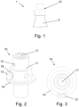
- a gas cartridge 1 according to an embodiment of the invention is shown.
- the gas cartridge 1 is configured to be connected to a gas cartridge connection of a water carbonator.
- the gas cartridge 1 comprises a receiving space 2 with an opening at which a valve 10 according to the invention is arranged for selectively closing and selectively opening the gas cartridge 1.
- a gas can be held in the gas cartridge 1 and in the open position a fluid connection can be provided in order to introduce gas into the gas cartridge 1 or to remove it from it.
- the Fig. 1 shows the area of the gas cartridge 1 that includes the valve 1.
- the gas cartridge 1 is shown in an upright position. In such an upright position, the gas cartridge 1 can be connected to the corresponding gas cartridge connection in a water carbonator.
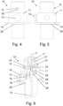
- the depictions in Fig. 2 to 7 show an embodiment of a valve 10 for selectively closing and selectively opening a gas cartridge 1 for a water carbonator, which in the case of the gas cartridge 1 according to Fig. 1 can be used.
- the valve 10 is designed to hold a gas in the gas cartridge 1 when it is closed and to provide a fluid connection to the gas cartridge 1 when it is opened.
- the valve 10 comprises a valve housing 11 having a cartridge connection opening 15 aligned along a longitudinal axis L of the valve 10 so that gas can flow into and out of the gas cartridge 1 in the direction of the longitudinal axis L.
- the valve housing 11 is connected to an annular retaining element 14, via which the valve 10 can be secured in a gas cartridge connection of a water carbonator.
- the retaining element 14 can be gripped by a suitable holding element of the water carbonator.
- the retaining element 14 is attached to the outside of the valve housing 11.
- a seal 20, here a sealing ring, is provided between the retaining element 14 and the valve housing 11.
- the retaining element 14 can be arranged between a projection of the valve housing 11 and a container housing of the gas cartridge 1. Alternatively, the retaining element 14 can be formed in one piece with the valve housing 11.
- a pressure relief valve 13 is arranged on the valve housing 11, which comprises a bursting disk 19.
- the pressure relief valve 13 can allow excess pressure in the area of the cartridge connection opening to escape by bursting the bursting disk 19.
- the valve 10 comprises several, here two, gas outlet elements 12, which are each arranged on the valve housing 11 so as to be movable between a rest position and a removal position and each have an outlet opening 16.
- a gas channel 31 is formed within the gas outlet element 16, which has an angled course starting from the interior of the valve housing 11 to the outlet opening 16.
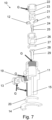
- the illustrations in Fig. 1 to 6 show the gas elements 12 in a rest position in which the gas outlet elements 12 are arranged within the valve housing 11 in such a way that they do not protrude from the valve housing 11. This rest position is therefore suitable for inserting the valve 10 into a gas cartridge connection of a water carbonator in order to connect the valve 10 to it.
- the outlet opening 16 is arranged inside the valve housing 11.
- a wall of the valve housing 11 covers the outlet opening 16 so that if there is an overpressure in the interior of the valve housing, gas cannot escape through the outlet opening 16. Rather, the entire gas outlet element 12 is moved out of the valve housing 11 starting from the rest position as a result of an overpressure in the interior of the valve housing 11, so that the respective gas outlet element 12 protrudes from the valve housing 11.
- the gas outlet elements 12 are mounted in guides in the valve housing 11, which are arranged obliquely, in particular perpendicularly, to the longitudinal axis L of the valve 10. Furthermore, the gas outlet elements 12 each have a stop 32, which limits the movement of the respective gas outlet element in the direction of the removal position.
- the stop 32 is designed as a projection according to the embodiment.
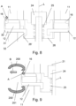
- FIG. 8 shows on the left a gas outlet element 12 in the removal position and on the right a gas outlet element 12 in the rest position.
- the gas outlet element 12 protrudes from the valve housing 11 so that the outlet opening 16 is arranged on the outside.
- the outlet opening 16 is also arranged along a direction parallel to the longitudinal axis L such that gas can flow out of the valve in the direction parallel to the longitudinal axis L, see arrow A.
- the stop 32 of the left gas outlet element 12 is in contact with a stop surface 26' in the interior of the valve housing 11.
- This stop surface 26 ⁇ is provided in the embodiment by an insert 26 in the interior of the valve housing 11, but can alternatively also be provided by an inner wall of the valve housing 11 itself.
- the removal position shown on the left represents a maximum extended removal position of the gas outlet element 12.
- An external actuating surface 30 is arranged on the gas outlet element 12 and is arranged at an angle to the longitudinal axis L.
- This actuating surface 30 is designed in the manner of a bevel and can be actuated from outside the valve 10 in order to move the gas outlet element 12 towards the rest position, i.e. to press it into the valve housing 11, for example when the valve 10 is removed from a gas cartridge connection of a water carbonator.
- the valve 10 further comprises a cartridge closure element 28 which is inserted into a Fig. 6 shown closed position, in which the cartridge closure element 28 closes a passage between the outlet openings 16 of the gas outlet elements 12 and the cartridge connection opening 15.
- the preload is brought about by a spring element 29.
- the cartridge closure element 28 can be moved against the preload by an actuating element 21 of the valve 10 in the direction of an open position, in which the passage between the outlet opening 16 and the cartridge connection opening 15 is opened for the discharge of gas.
- the actuating element 21 is arranged externally on a side of the valve 10 opposite the cartridge connection opening 15 and can be moved in the direction of the longitudinal axis L in order to discharge gas from the valve 10.
- the actuating element 21 is coupled to the cartridge closure element 28 via an inlet closure element 24 such that a compressive force can be transmitted to the cartridge closure element 28.
- the inlet closure element 24 closes a filling opening 17 which is arranged in the actuating element 21.
- the filling opening is configured so that gas can flow into the valve 10 in the direction of the longitudinal axis L, provided that the inlet closure element 24 releases it.
- the inlet closure element 24 is pushed into the position shown in the Fig. 6 shown closed position, in which the inlet closure element 24 closes the filling opening.
- the spring element 25 is configured such that the inlet closure element 24 can be brought into an open position by applying a predetermined gas pressure to the filling opening 17, in which the filling opening 17 is opened for the introduction of gas.
- gas can be introduced through the filling opening 17 into the interior of the valve housing 11 and then guided through the passage in the insert 26 in the direction of the cartridge connection opening 15.
- a detailed representation of a gas outlet element 12 of a valve 10 is shown, which is connected to a gas cartridge connection of a water carbonator.
- the gas cartridge connection comprises a sealing device 200, 200 ⁇ , which rests against the outer contour of the valve 10 and seals an area around the outlet opening 16.
- the sealing device has an upper sealing section 200 which seals above the outlet opening 16 and a lower sealing section 200' which seals below the outlet opening 16.
- a sealed space 201 is thus created, in which the gas flowing out of the outlet opening 16 parallel to the longitudinal direction L is received.
- This sealed space 201 can be designed in such a way that the gas is discharged in a direction oblique to the longitudinal axis L, see arrow B.
- the gas can then be conducted, for example via a line, to a carbonation device of the water carbonator, via which the gas can be introduced into a container filled with water.
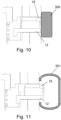
- FIG. 10 and 11 show conditions that occur when filling the Fig. 1 shown gas cartridge 1 can be taken in via the filling opening 17 on the side of the valve 10 opposite the cartridge connection opening 15 in order to seal a fluid connection between the outlet opening 16 of the gas outlet elements 12 and the environment. This is necessary in order to prevent an undesired escape of the gas via the outlet openings 16 when gas is introduced via the filling opening 17. Rather, the gas introduced into the valve 10 via the filling opening 17 can then be guided into the receiving space of the gas cartridge 1 via the cartridge connection opening 15.
- the gas outlet elements 12 are fixed in their rest position via a locking element 300.
- the locking element 300 can be arranged on the outer contour of the valve housing 11 in such a way that an undesired extension of the gas outlet element 12 is prevented.
- the gas outlet elements 12 can be either in their rest position or - as shown - in the removal position.
- a sealing element 301 is arranged on the outer contour of the valve housing 11, which seals the area around the outlet opening 16 from the environment.
Landscapes
- Engineering & Computer Science (AREA)
- Mechanical Engineering (AREA)
- General Engineering & Computer Science (AREA)
- Filling Or Discharging Of Gas Storage Vessels (AREA)
Applications Claiming Priority (1)
| Application Number | Priority Date | Filing Date | Title |
|---|---|---|---|
| DE102022204528 | 2022-05-09 |
Publications (3)
| Publication Number | Publication Date |
|---|---|
| EP4276348A1 EP4276348A1 (de) | 2023-11-15 |
| EP4276348C0 EP4276348C0 (de) | 2024-11-20 |
| EP4276348B1 true EP4276348B1 (de) | 2024-11-20 |
Family
ID=86330540
Family Applications (1)
| Application Number | Title | Priority Date | Filing Date |
|---|---|---|---|
| EP23172061.6A Active EP4276348B1 (de) | 2022-05-09 | 2023-05-08 | Ventil für eine gaskartusche, gaskartusche für einen wassersprudler und verfahren zum befüllen einer solchen gaskartusche |
Country Status (4)
| Country | Link |
|---|---|
| EP (1) | EP4276348B1 (pl) |
| ES (1) | ES3010647T3 (pl) |
| HU (1) | HUE070109T2 (pl) |
| PL (1) | PL4276348T3 (pl) |
Families Citing this family (1)
| Publication number | Priority date | Publication date | Assignee | Title |
|---|---|---|---|---|
| CA3255382A1 (en) | 2022-05-27 | 2025-04-26 | Sodapop Gmbh | VALVE FOR GAS CARTRIDGE, GAS CARTRIDGE FOR A WATER GASING DEVICE AND METHOD FOR FILLING SUCH A GAS CARTRIDGE |
Citations (8)
| Publication number | Priority date | Publication date | Assignee | Title |
|---|---|---|---|---|
| US4760865A (en) | 1985-09-11 | 1988-08-02 | Rilett John W | Container valve |
| US8171950B2 (en) | 2007-01-30 | 2012-05-08 | Ysn Imports, Inc. | Compressed air regulator apparatus situated in canister and method for regulating compressed air thereof |
| US20130213492A1 (en) | 2012-02-08 | 2013-08-22 | Shmuel Dovid Newman | Valve assembly for compressed air cartridge |
| US20180239375A1 (en) | 2016-12-13 | 2018-08-23 | Douglas C. Heiderman | Gas delivery valve and methods of use thereof |
| WO2019110714A1 (en) | 2017-12-06 | 2019-06-13 | Micro Matic A/S | A valve assembly |
| US10625919B2 (en) | 2015-06-11 | 2020-04-21 | Innveri Ag | Device for preserving beverages |
| WO2020230115A1 (en) | 2019-05-14 | 2020-11-19 | Sodastream Industries Ltd. | Carbonation machine and a gas canister for a carbonation machine |
| DE102019217896A1 (de) | 2019-11-20 | 2021-05-20 | Andreas Jahn | Druckbehälter und Verfahren zur Herstellung eines Druckbehälters |
Family Cites Families (5)
| Publication number | Priority date | Publication date | Assignee | Title |
|---|---|---|---|---|
| DE19927667A1 (de) | 1999-06-17 | 2000-12-21 | Brita Gmbh | Auslaßventil für CO2-Druckflaschen |
| CZ10395U1 (en) * | 2000-06-07 | 2000-09-01 | Dgf A S | Valve for pressure bottles |
| DE20013847U1 (de) * | 2000-08-11 | 2000-12-28 | Eggert, Armin, 99518 Bad Sulza | Ventil für Druckbehälter |
| EP3614036B1 (de) * | 2018-08-24 | 2021-11-10 | Kwc Ag | Anschlussvorrichtung für einen gasdruckbehälter |
| DE202021101309U1 (de) * | 2021-03-16 | 2021-04-20 | Markus Mayer | Adapteranordnung |
-
2023
- 2023-05-08 PL PL23172061.6T patent/PL4276348T3/pl unknown
- 2023-05-08 HU HUE23172061A patent/HUE070109T2/hu unknown
- 2023-05-08 ES ES23172061T patent/ES3010647T3/es active Active
- 2023-05-08 EP EP23172061.6A patent/EP4276348B1/de active Active
Patent Citations (9)
| Publication number | Priority date | Publication date | Assignee | Title |
|---|---|---|---|---|
| US4760865A (en) | 1985-09-11 | 1988-08-02 | Rilett John W | Container valve |
| US8171950B2 (en) | 2007-01-30 | 2012-05-08 | Ysn Imports, Inc. | Compressed air regulator apparatus situated in canister and method for regulating compressed air thereof |
| US20130213492A1 (en) | 2012-02-08 | 2013-08-22 | Shmuel Dovid Newman | Valve assembly for compressed air cartridge |
| US10625919B2 (en) | 2015-06-11 | 2020-04-21 | Innveri Ag | Device for preserving beverages |
| US20180239375A1 (en) | 2016-12-13 | 2018-08-23 | Douglas C. Heiderman | Gas delivery valve and methods of use thereof |
| WO2019110714A1 (en) | 2017-12-06 | 2019-06-13 | Micro Matic A/S | A valve assembly |
| WO2020230115A1 (en) | 2019-05-14 | 2020-11-19 | Sodastream Industries Ltd. | Carbonation machine and a gas canister for a carbonation machine |
| WO2021137206A1 (en) | 2019-05-14 | 2021-07-08 | Sodastream Industries Ltd. | Adapter for canister filling system and method for filling a gas canister |
| DE102019217896A1 (de) | 2019-11-20 | 2021-05-20 | Andreas Jahn | Druckbehälter und Verfahren zur Herstellung eines Druckbehälters |
Non-Patent Citations (2)
| Title |
|---|
| ANONYMOUS: "CGA S-1.1: Pressure Relief Device Standards", COMPRESSED GAS ASSOCIATION, 1 January 2005 (2005-01-01), XP093308209 |
| ANONYMOUS: "HIGH PRESSURE CYLINDER VALVES PRODUCT CATALOGUE", TEKNO VALVES, 29 December 2020 (2020-12-29), XP093308210, Retrieved from the Internet <URL:https://www.teknovalves.com/files/catalog/CylinderValves/Product-Catalogue-E.pdf> |
Also Published As
| Publication number | Publication date |
|---|---|
| ES3010647T3 (en) | 2025-04-04 |
| EP4276348C0 (de) | 2024-11-20 |
| PL4276348T3 (pl) | 2025-04-22 |
| HUE070109T2 (hu) | 2025-05-28 |
| EP4276348A1 (de) | 2023-11-15 |
Similar Documents
| Publication | Publication Date | Title |
|---|---|---|
| EP3696455B1 (de) | Elektromagnetisch betätigtes ventil | |
| DE9013730U1 (de) | Einweg-Druckbehälter, insbesondere als Nachfüllbehälter für Kälte- und Klima-Anlagen | |
| EP4384749B1 (de) | Ventil für eine gaskartusche, gaskartusche für einen wassersprudler und verfahren zum befüllen einer solchen gaskartusche | |
| EP4276348B1 (de) | Ventil für eine gaskartusche, gaskartusche für einen wassersprudler und verfahren zum befüllen einer solchen gaskartusche | |
| EP0568005B1 (de) | Tankentlüftungsventil | |
| DE68907562T2 (de) | Absperrventil. | |
| DE3412351A1 (de) | Magnetventil zum regeln des bremsdruckes in einem bremszylinder eines kraftfahrzeuges | |
| EP0008702A1 (de) | Vorrichtung zur Sperrung bzw. Freigabe des Durchflusses eines fliessfähigen Mediums | |
| DE69705699T2 (de) | Ventil | |
| EP1124738A1 (de) | Ventil für die abgabe von unter druck stehenden flüssigkeiten | |
| DE10020903A1 (de) | Druckmittelspeicher | |
| EP0066734B1 (de) | Ausblas-Einrichtung für Ausstoss- und Ablaufrohre von U-Booten | |
| EP0935993A1 (de) | Vorrichtung zum Anreichern von Flüssigkeiten mit Gasen | |
| DE3337197C2 (pl) | ||
| DE1900360C3 (de) | Schaltventil mit berührungsfreier Schaltbewegung der Ventilplatte gegenüber dem Ventilsitz | |
| DE19805198A1 (de) | Vorrichtung zum Anreichern von Flüssigkeiten mit Gasen | |
| EP0140106A2 (de) | Entnahmeventil zur Entnahme verflüssigter Treibgase aus einem Vorratsbehälter | |
| DE102023206095B3 (de) | Befülleinrichtung und Verfahren zum Befüllen einer Gaskartusche mit Druckgas oder Flüssiggas | |
| DE3220867A1 (de) | Vorgesteuertes magnetventil | |
| DE102023100744B4 (de) | Feuerlöschanordnung mit Auslöseventil | |
| DE1951465A1 (de) | Sicherheitsvorrichtung fuer Kessel-Bodenventile | |
| DE10357401B4 (de) | Entleerungsventil | |
| DE19951248C1 (de) | Vorrichtung zum Zuführen eines flüssigen Reinigungsmittels und zum Zu- und Abführen eines gasförmigen Mittels an einem Flüssigkeitstank, insbesondere Biertank | |
| WO2025008387A1 (de) | Verfahren zum befüllen einer gaskartusche mit druckgas oder flüssiggas | |
| DE29921157U1 (de) | Rückschlagventil |
Legal Events
| Date | Code | Title | Description |
|---|---|---|---|
| PUAI | Public reference made under article 153(3) epc to a published international application that has entered the european phase |
Free format text: ORIGINAL CODE: 0009012 |
|
| STAA | Information on the status of an ep patent application or granted ep patent |
Free format text: STATUS: THE APPLICATION HAS BEEN PUBLISHED |
|
| AK | Designated contracting states |
Kind code of ref document: A1 Designated state(s): AL AT BE BG CH CY CZ DE DK EE ES FI FR GB GR HR HU IE IS IT LI LT LU LV MC ME MK MT NL NO PL PT RO RS SE SI SK SM TR |
|
| STAA | Information on the status of an ep patent application or granted ep patent |
Free format text: STATUS: REQUEST FOR EXAMINATION WAS MADE |
|
| 17P | Request for examination filed |
Effective date: 20240321 |
|
| RBV | Designated contracting states (corrected) |
Designated state(s): AL AT BE BG CH CY CZ DE DK EE ES FI FR GB GR HR HU IE IS IT LI LT LU LV MC ME MK MT NL NO PL PT RO RS SE SI SK SM TR |
|
| GRAP | Despatch of communication of intention to grant a patent |
Free format text: ORIGINAL CODE: EPIDOSNIGR1 |
|
| STAA | Information on the status of an ep patent application or granted ep patent |
Free format text: STATUS: GRANT OF PATENT IS INTENDED |
|
| INTG | Intention to grant announced |
Effective date: 20240613 |
|
| RIC1 | Information provided on ipc code assigned before grant |
Ipc: F17C 13/04 20060101AFI20240531BHEP |
|
| TPAC | Observations filed by third parties |
Free format text: ORIGINAL CODE: EPIDOSNTIPA |
|
| TPAC | Observations filed by third parties |
Free format text: ORIGINAL CODE: EPIDOSNTIPA |
|
| TPAC | Observations filed by third parties |
Free format text: ORIGINAL CODE: EPIDOSNTIPA |
|
| GRAS | Grant fee paid |
Free format text: ORIGINAL CODE: EPIDOSNIGR3 |
|
| GRAA | (expected) grant |
Free format text: ORIGINAL CODE: 0009210 |
|
| STAA | Information on the status of an ep patent application or granted ep patent |
Free format text: STATUS: THE PATENT HAS BEEN GRANTED |
|
| AK | Designated contracting states |
Kind code of ref document: B1 Designated state(s): AL AT BE BG CH CY CZ DE DK EE ES FI FR GB GR HR HU IE IS IT LI LT LU LV MC ME MK MT NL NO PL PT RO RS SE SI SK SM TR |
|
| REG | Reference to a national code |
Ref country code: GB Ref legal event code: FG4D Free format text: NOT ENGLISH |
|
| REG | Reference to a national code |
Ref country code: CH Ref legal event code: EP |
|
| REG | Reference to a national code |
Ref country code: DE Ref legal event code: R096 Ref document number: 502023000308 Country of ref document: DE |
|
| REG | Reference to a national code |
Ref country code: IE Ref legal event code: FG4D Free format text: LANGUAGE OF EP DOCUMENT: GERMAN |
|
| U01 | Request for unitary effect filed |
Effective date: 20241205 |
|
| U07 | Unitary effect registered |
Designated state(s): AT BE BG DE DK EE FI FR IT LT LU LV MT NL PT RO SE SI Effective date: 20241216 |
|
| REG | Reference to a national code |
Ref country code: SK Ref legal event code: T3 Ref document number: E 45911 Country of ref document: SK |
|
| REG | Reference to a national code |
Ref country code: ES Ref legal event code: FG2A Ref document number: 3010647 Country of ref document: ES Kind code of ref document: T3 Effective date: 20250404 |
|
| PG25 | Lapsed in a contracting state [announced via postgrant information from national office to epo] |
Ref country code: IS Free format text: LAPSE BECAUSE OF FAILURE TO SUBMIT A TRANSLATION OF THE DESCRIPTION OR TO PAY THE FEE WITHIN THE PRESCRIBED TIME-LIMIT Effective date: 20250320 Ref country code: HR Free format text: LAPSE BECAUSE OF FAILURE TO SUBMIT A TRANSLATION OF THE DESCRIPTION OR TO PAY THE FEE WITHIN THE PRESCRIBED TIME-LIMIT Effective date: 20241120 |
|
| PG25 | Lapsed in a contracting state [announced via postgrant information from national office to epo] |
Ref country code: NO Free format text: LAPSE BECAUSE OF FAILURE TO SUBMIT A TRANSLATION OF THE DESCRIPTION OR TO PAY THE FEE WITHIN THE PRESCRIBED TIME-LIMIT Effective date: 20250220 |
|
| PG25 | Lapsed in a contracting state [announced via postgrant information from national office to epo] |
Ref country code: GR Free format text: LAPSE BECAUSE OF FAILURE TO SUBMIT A TRANSLATION OF THE DESCRIPTION OR TO PAY THE FEE WITHIN THE PRESCRIBED TIME-LIMIT Effective date: 20250221 |
|
| PG25 | Lapsed in a contracting state [announced via postgrant information from national office to epo] |
Ref country code: RS Free format text: LAPSE BECAUSE OF FAILURE TO SUBMIT A TRANSLATION OF THE DESCRIPTION OR TO PAY THE FEE WITHIN THE PRESCRIBED TIME-LIMIT Effective date: 20250220 |
|
| REG | Reference to a national code |
Ref country code: HU Ref legal event code: AG4A Ref document number: E070109 Country of ref document: HU |
|
| U20 | Renewal fee for the european patent with unitary effect paid |
Year of fee payment: 3 Effective date: 20250516 |
|
| PG25 | Lapsed in a contracting state [announced via postgrant information from national office to epo] |
Ref country code: SM Free format text: LAPSE BECAUSE OF FAILURE TO SUBMIT A TRANSLATION OF THE DESCRIPTION OR TO PAY THE FEE WITHIN THE PRESCRIBED TIME-LIMIT Effective date: 20241120 |
|
| PGFP | Annual fee paid to national office [announced via postgrant information from national office to epo] |
Ref country code: PL Payment date: 20250506 Year of fee payment: 3 |
|
| PGFP | Annual fee paid to national office [announced via postgrant information from national office to epo] |
Ref country code: ES Payment date: 20250616 Year of fee payment: 3 |
|
| PGFP | Annual fee paid to national office [announced via postgrant information from national office to epo] |
Ref country code: HU Payment date: 20250602 Year of fee payment: 3 |
|
| PGFP | Annual fee paid to national office [announced via postgrant information from national office to epo] |
Ref country code: SK Payment date: 20250506 Year of fee payment: 3 |
|
| PG25 | Lapsed in a contracting state [announced via postgrant information from national office to epo] |
Ref country code: CZ Free format text: LAPSE BECAUSE OF FAILURE TO SUBMIT A TRANSLATION OF THE DESCRIPTION OR TO PAY THE FEE WITHIN THE PRESCRIBED TIME-LIMIT Effective date: 20241120 |
|
| PGFP | Annual fee paid to national office [announced via postgrant information from national office to epo] |
Ref country code: IE Payment date: 20250522 Year of fee payment: 3 |
|
| PLBI | Opposition filed |
Free format text: ORIGINAL CODE: 0009260 |
|
| PLAX | Notice of opposition and request to file observation + time limit sent |
Free format text: ORIGINAL CODE: EPIDOSNOBS2 |
|
| 26 | Opposition filed |
Opponent name: SODASTREAM INDUSTRIES LTD. Effective date: 20250819 |