EP4275653A1 - Intraokularlinse mit einer aufspannvorrichtung - Google Patents
Intraokularlinse mit einer aufspannvorrichtung Download PDFInfo
- Publication number
- EP4275653A1 EP4275653A1 EP23169846.5A EP23169846A EP4275653A1 EP 4275653 A1 EP4275653 A1 EP 4275653A1 EP 23169846 A EP23169846 A EP 23169846A EP 4275653 A1 EP4275653 A1 EP 4275653A1
- Authority
- EP
- European Patent Office
- Prior art keywords
- clamping device
- clamped state
- longitudinal end
- intraocular lens
- haptic
- Prior art date
- Legal status (The legal status is an assumption and is not a legal conclusion. Google has not performed a legal analysis and makes no representation as to the accuracy of the status listed.)
- Granted
Links
Images


Classifications
-
- A—HUMAN NECESSITIES
- A61—MEDICAL OR VETERINARY SCIENCE; HYGIENE
- A61F—FILTERS IMPLANTABLE INTO BLOOD VESSELS; PROSTHESES; DEVICES PROVIDING PATENCY TO, OR PREVENTING COLLAPSING OF, TUBULAR STRUCTURES OF THE BODY, e.g. STENTS; ORTHOPAEDIC, NURSING OR CONTRACEPTIVE DEVICES; FOMENTATION; TREATMENT OR PROTECTION OF EYES OR EARS; BANDAGES, DRESSINGS OR ABSORBENT PADS; FIRST-AID KITS
- A61F2/00—Filters implantable into blood vessels; Prostheses, i.e. artificial substitutes or replacements for parts of the body; Appliances for connecting them with the body; Devices providing patency to, or preventing collapsing of, tubular structures of the body, e.g. stents
- A61F2/02—Prostheses implantable into the body
- A61F2/14—Eye parts, e.g. lenses or corneal implants; Artificial eyes
- A61F2/16—Intraocular lenses
-
- A—HUMAN NECESSITIES
- A61—MEDICAL OR VETERINARY SCIENCE; HYGIENE
- A61F—FILTERS IMPLANTABLE INTO BLOOD VESSELS; PROSTHESES; DEVICES PROVIDING PATENCY TO, OR PREVENTING COLLAPSING OF, TUBULAR STRUCTURES OF THE BODY, e.g. STENTS; ORTHOPAEDIC, NURSING OR CONTRACEPTIVE DEVICES; FOMENTATION; TREATMENT OR PROTECTION OF EYES OR EARS; BANDAGES, DRESSINGS OR ABSORBENT PADS; FIRST-AID KITS
- A61F2/00—Filters implantable into blood vessels; Prostheses, i.e. artificial substitutes or replacements for parts of the body; Appliances for connecting them with the body; Devices providing patency to, or preventing collapsing of, tubular structures of the body, e.g. stents
- A61F2/02—Prostheses implantable into the body
- A61F2/14—Eye parts, e.g. lenses or corneal implants; Artificial eyes
- A61F2/16—Intraocular lenses
- A61F2002/1681—Intraocular lenses having supporting structure for lens, e.g. haptics
- A61F2002/1683—Intraocular lenses having supporting structure for lens, e.g. haptics having filiform haptics
- A61F2002/1686—Securing a filiform haptic to a lens body
-
- A—HUMAN NECESSITIES
- A61—MEDICAL OR VETERINARY SCIENCE; HYGIENE
- A61F—FILTERS IMPLANTABLE INTO BLOOD VESSELS; PROSTHESES; DEVICES PROVIDING PATENCY TO, OR PREVENTING COLLAPSING OF, TUBULAR STRUCTURES OF THE BODY, e.g. STENTS; ORTHOPAEDIC, NURSING OR CONTRACEPTIVE DEVICES; FOMENTATION; TREATMENT OR PROTECTION OF EYES OR EARS; BANDAGES, DRESSINGS OR ABSORBENT PADS; FIRST-AID KITS
- A61F2/00—Filters implantable into blood vessels; Prostheses, i.e. artificial substitutes or replacements for parts of the body; Appliances for connecting them with the body; Devices providing patency to, or preventing collapsing of, tubular structures of the body, e.g. stents
- A61F2/02—Prostheses implantable into the body
- A61F2/14—Eye parts, e.g. lenses or corneal implants; Artificial eyes
- A61F2/16—Intraocular lenses
- A61F2002/1681—Intraocular lenses having supporting structure for lens, e.g. haptics
- A61F2002/16901—Supporting structure conforms to shape of capsular bag
-
- A—HUMAN NECESSITIES
- A61—MEDICAL OR VETERINARY SCIENCE; HYGIENE
- A61F—FILTERS IMPLANTABLE INTO BLOOD VESSELS; PROSTHESES; DEVICES PROVIDING PATENCY TO, OR PREVENTING COLLAPSING OF, TUBULAR STRUCTURES OF THE BODY, e.g. STENTS; ORTHOPAEDIC, NURSING OR CONTRACEPTIVE DEVICES; FOMENTATION; TREATMENT OR PROTECTION OF EYES OR EARS; BANDAGES, DRESSINGS OR ABSORBENT PADS; FIRST-AID KITS
- A61F2/00—Filters implantable into blood vessels; Prostheses, i.e. artificial substitutes or replacements for parts of the body; Appliances for connecting them with the body; Devices providing patency to, or preventing collapsing of, tubular structures of the body, e.g. stents
- A61F2/02—Prostheses implantable into the body
- A61F2/14—Eye parts, e.g. lenses or corneal implants; Artificial eyes
- A61F2/16—Intraocular lenses
- A61F2002/1681—Intraocular lenses having supporting structure for lens, e.g. haptics
- A61F2002/16905—Having means on lens to reduce overall dimension of lens for insertion into small incision
Definitions
- the invention relates to an intraocular lens with a clamping device.
- Cataract treatment involves replacing a natural lens in the human eye with an artificial intraocular lens.
- the natural lens is crushed using phacoemulsification, for example, and then sucked out of a capsular bag of the eye.
- a lens capsule of the lens remains in the capsular bag.
- the intraocular lens usually has a substantially planar shape. This allows the lens capsule to touch the intraocular lens in a rear area of the capsular bag. This can lead to a so-called after-cataract occurring several months or even years after cataract treatment, which leads to clouding of the lens capsule in the rear area of the capsular bag. The clouding is accompanied by a deterioration in vision.
- the secondary cataract can be treated with a so-called capsulotomy.
- the cloudiness can, for example, be exposed to several pulses of laser radiation. However, it would be desirable if the after-cataract did not occur at all after cataract treatment.
- US 2010 / 0 228 344 A1 discloses a deformable intracapsular implantation device for deforming an enucleated capsular bag.
- the object of the invention is therefore to create an intraocular lens in which the probability of a secondary cataract occurring after cataract treatment is low.
- a first intraocular lens according to the invention has an optical body that has an optical axis and a haptic that has a haptic arm and a clamping device.
- the haptic arm is attached to the optical body and has a first longitudinal end, which is arranged facing the optical body, and a second longitudinal end, which is arranged away from the optical body.
- the clamping device is attached to the second longitudinal end, has a shape memory material with a transition temperature and a longitudinal end.
- the clamping device has a clamped state in which the longitudinal end is that part of the surface of the clamping device which is furthest from the haptic arm in a direction perpendicular to a radial direction with respect to the optical axis, and a non-clamped state in which the longitudinal end is less far from the haptic arm in the direction perpendicular to the radial direction than in the clamped state, the clamping device being set up to move from the non-clamped state to the clamped state by exceeding the transition temperature.
- a second intraocular lens according to the invention has an optical body that has an optical axis and a haptic that has a haptic arm and a clamping device.
- the haptic arm is attached to the optical body and has a first longitudinal end, which is arranged facing the optical body, and a second longitudinal end, which is arranged away from the optical body.
- the jig is attached to the second longitudinal end, has a pseudo-elastic material and a longitudinal end.
- the clamping device has a clamped state in which the longitudinal end is that part of the surface of the clamping device which is furthest from the haptic arm in a direction perpendicular to a radial direction with respect to the optical axis, and a non-clamped state in which the longitudinal end is less far away from the haptic arm in the direction perpendicular to the radial direction than in the clamped state, the clamping device being set up such that when a force is applied to the clamping device in the direction of the haptic arm, the clamping device moves from the clamped state to the non-clamped state State and after a loss of force from the unclamped state to the clamped state.
- the clamping device In the clamped state, the clamping device is bulkier than in the non-clamped state. This makes it easier for the intraocular lens to be pushed through a tip of an injector in the unclamped state in order to be injected into the capsular bag of an eye during cataract treatment. Damage to the clamping device while the intraocular lens is pushed through the tip is unlikely in the unclamped state.
- the clamping device can be brought into the clamped state in the capsular bag.
- this is done by heating the shape memory material from a temperature below the transition temperature to a temperature above the transition temperature. This can be done, for example, by heating using body heat, by applying electromagnetic radiation, in particular laser radiation, and/or by applying an alternating magnetic field.
- the intraocular lens can have magnetic particles and/or magnetizable particles that convert the energy of the alternating magnetic field into heat.
- the clamping device can be brought into the unclamped state by pressing the intraocular lens into the tip of the injector and thus applying the force to the clamping device in the direction of the haptic arm. After leaving the tip, this force is eliminated and the clamping device thus reaches the clamped state in the capsular bag. In the clamped state, the clamping device clamps the capsular bag, whereby the capsular bag is arranged further away from the optical body than with a conventional intraocular lens, which is designed to be planar. This allows fluid in the capsular bag to circulate better than with the conventional intraocular lens, which means there is little chance that a secondary cataract will form after cataract treatment.
- the shape memory material is designed to transport the clamping device from the non-clamped state to the clamped state by changing its curvature.
- the curvature of the shape memory material decreases when the transition temperature is exceeded.
- the transition temperature is preferably a maximum of 35°C. This makes it possible for the transition temperature to be exceeded by heating using body heat. It is preferred that the transition temperature is at least 25°C or at least 30°C. This can prevent the transition temperature from being exceeded while the intraocular lens is being stored.
- the shape memory material preferably has a polymer or preferably consists of the polymer.
- the polymer can be, for example, a poly(meth)acrylic acid, especially if the intraocular lens is hydrophobic.
- the polymer can be a 2-hydroxyethyl methacrylate and/or a 6-hydroxyhexyl methacrylate, particularly if the intraocular lens is hydrophilic.
- the clamping device consists of the polymer.
- the entire haptic and/or the optical body consists of the polymer.
- the optical body and/or the haptic arm has a different material than the polymer.
- the shape memory material preferably has an alloy or preferably consists of the alloy.
- such an alloy may contain nickel and titanium.
- Such an alloy is known as Nitinol.
- the clamping device particularly preferably has a plastic in which the alloy is introduced.
- the plastic can be, for example, the material of the optical body, such as an acrylic resin.
- the plastic can also be polyurethane, polyvinylidene fluoride and/or polytetrafluoroethylene.
- the alloy is particularly preferably coated, in particular with the acrylic resin, the polyurethane, the polyvinylidene fluoride and/or the polytetrafluoroethylene. It is also conceivable to treat the alloy with phosphorylcholine in order to coat the alloy.
- the pseudoelastic material can be a shape memory material, in particular a shape memory alloy, in which, in addition to the usual elastic deformation, a reversible shape change caused by external force is observed.
- the pseudo-elastic material is preferably designed to transport the clamping device from the non-clamped state to the clamped state by changing its curvature.
- the pseudoelastic material can be Nitinol.
- the curvature of the pseudoelastic material may decrease when the clamping device moves from the non-clamped state to the clamped state.
- the clamping device in the non-clamped state extends completely around the haptic arm and the clamping device has an edge that is designed to be closed and in the clamped state that in the direction perpendicular to the radial direction is the outer end of the clamping device.
- the clamping device moves away from the haptic arm along the entire circumference around the haptic arm, like an umbrella, when the clamping device moves from the unclamped state to the clamped state. This allows the capsular bag to be stretched particularly wide. It is particularly preferred that in the stretched state the edge has the shape of a circle.
- the clamping device preferably has several of the longitudinal ends. This allows the capsular bag to be stretched particularly wide.
- the intraocular lens has at least two of the haptics. This allows the capsular bag to be stretched particularly wide.
- the number of haptics is particularly preferably even, in particular the number of haptics is 2 or 4.
- an intraocular lens 1 has an optical body 2, which has an optical axis 3, and a haptic 11 to 14, which has a haptic arm 15 and a clamping device 21.
- the haptic arm 15 is attached to the optical body 2 and has a first longitudinal end 16, which is arranged facing the optical body 2, and a second longitudinal end 17, which is arranged facing away from the optical body 2.
- the clamping device 21 is attached to the second longitudinal end 17 and has a longitudinal end 22.
- the clamping device 21 is in a clamped state (see Figure 2 ), in which the longitudinal end 22 is that part of the surface of the clamping device 21 which is furthest away from the haptic arm 15 in a direction perpendicular to a radial direction 6 with respect to the optical axis 3, and an unclamped state (see Figure 2 ), in which the longitudinal end 22 is less far away from the haptic arm 15 in the direction perpendicular to the radial direction 6 than in the clamped state.
- the clamping device 21 has a shape memory material with a transition temperature and that the clamping device 21 is set up exceeding the transition temperature from the unclamped state to the clamped state.
- the transition temperature can, for example, be in a range from 25°C to 35°C or from 30°C to 35°C.
- the clamping device 21 has a pseudo-elastic material and that the clamping device 21 is set up so that when a force is applied to the clamping device 21 in the direction of the haptic arm 15, the clamping device 21 moves from the clamped state to the non-clamped state and after when the force is lost, it moves from the unclamped state to the clamped state.
- FIG. 1 A comparison of Figure 1 with Figure 2 shows that the shape memory material can be set up to transport the clamping device 21 from the non-clamped state to the clamped state by reducing its curvature.
- the pseudo-elastic material can be designed to transport the clamping device 21 from the non-clamped state to the clamped state by reducing its curvature.
- Figures 1 to 4 show that the intraocular lens 1 can have at least two of the haptics 11 to 14.
- the haptics 11 to 14 can, for example, be arranged uniformly around the optical body 2 in a circumferential direction 5 with respect to the optical axis 3. It is conceivable that the number of haptics 11 to 14 is even, in particular the number of haptics can be two (see Figure 3 ) or four (see Figures 1, 2 and 4 ) be.
- the haptic arms 15 can, for example, have the shape of a rod, compare Figures 1 to 12 .
- the haptic arms 15 can be oriented, for example, in a radial direction 6 with respect to the optical axis 3, compare Figure 3 .
- the haptic arms 15 are inclined towards the optical axis 3, compare Figure 4 .
- the haptic arms 15 are alternately inclined in opposite directions in the circumferential direction 5. This allows the capsular bag to be stretched particularly wide.
- Figures 5 to 12 show various embodiments for the haptic 11, with the clamping device 21 of the haptic 11 being shown in the clamped state.
- the clamping device 21 In the non-clamped state, the clamping device 21 can extend completely around the haptic arm 15 and the clamping device 21 can have an edge 23 which is closed and in the clamped state is the outer end of the clamping device 21 in the direction perpendicular to the radial direction 6 , compare Figures 5 to 10 .
- Figure 6 shows that in the stretched state the edge 23 can have the shape of a circle.
- the edge 23 can be arranged symmetrically to the haptic arm 15 so that the longitudinal end 22 and the edge 23 coincide.
- the clamping device 21 can have several of the longitudinal ends 22.
- the clamping device 21 can be flower-shaped, compare Figures 7 to 10 .
- the edge 23 alternately has the longitudinal ends 22 and minima 24, which are less far away from the haptic arm 15 than the longitudinal ends 22 in the direction perpendicular to the radial direction 6.
- the minima 24 are significantly more pronounced than in the embodiment according to Figures 7 and 8 .
- the distance from the haptic arm 15 to the minima 24 can be in a range from 20% to 90%, preferably from 40% to 60%, of the distance from the haptic arm 15 to the longitudinal ends 22.
- Figures 5 to 12 show that the shape memory material and/or the pseudoelastic material may comprise a metal or an alloy.
- the Shape memory material and / or the pseudoelastic material is introduced into a plastic.
- the shape memory material and/or the pseudoelastic material has the shape of a ring 25, in particular a circular ring.
- the shape memory material and/or the pseudoelastic material has a closed waveform 26.
- the shape memory material and/or the pseudoelastic material is in the form of several wires 27.
- each of the wires 27 extends from one of the longitudinal ends 22 to another of the longitudinal ends 22. In the case that the number of the longitudinal ends 22 is odd, each of the wires extends 27 starting from the second longitudinal end 17 of the haptic arm 15 up to one of the longitudinal ends 22.
- the shape memory material and/or the pseudoelastic material is coated in order to achieve good biocompatibility.
- the shape memory material is a polymer.
- the clamping device can consist of the polymer.
- the polymer can be, for example, a poly(meth)acrylic acid, especially if the intraocular lens is hydrophobic.
- the polymer can be a 2-hydroxyethyl methacrylate and/or a 6-hydroxyhexyl methacrylate, particularly if the intraocular lens is hydrophilic.
Landscapes
- Health & Medical Sciences (AREA)
- Ophthalmology & Optometry (AREA)
- Cardiology (AREA)
- Oral & Maxillofacial Surgery (AREA)
- Transplantation (AREA)
- Engineering & Computer Science (AREA)
- Biomedical Technology (AREA)
- Heart & Thoracic Surgery (AREA)
- Vascular Medicine (AREA)
- Life Sciences & Earth Sciences (AREA)
- Animal Behavior & Ethology (AREA)
- General Health & Medical Sciences (AREA)
- Public Health (AREA)
- Veterinary Medicine (AREA)
- Prostheses (AREA)
Abstract
Description
- Die Erfindung betrifft eine Intraokularlinse mit einer Aufspannvorrichtung.
- Bei einer Kataraktbehandlung wird eine natürliche Linse des menschlichen Auges durch eine künstliche Intraokularlinse ersetzt. Dazu wird die natürliche Linse beispielsweise mittels Phakoemulsifikation zerkleinert und anschließend aus einem Kapselsack des Auges abgesaugt. Bei einer extrakapsulären Katarakt-Extraktion verbleibt eine Linsenkapsel der Linse dabei in dem Kapselsack. Die Intraokularlinse hat in der Regel eine im Wesentlichen planare Form. Dadurch kann die Linsenkapsel in einem hinteren Bereich des Kapselsacks die Intraokularlinse berühren. Dies kann dazu führen, dass mehrere Monate oder sogar Jahre nach der Kataraktbehandlung ein sogenannter Nachstar entstehen kann, der zu einer Trübung der Linsenkapsel in dem hinteren Bereich des Kapselsacks führt. Die Trübung geht einher mit einer Verschlechterung des Sehens. Der Nachstar kann durch eine sogenannte Kapsulotomie behandelt werden. Dabei kann die Trübung beispielsweise mit mehreren Impulsen von Laserstrahlung beaufschlagt werden. Wünschenswert wäre es jedoch, wenn der Nachstar nach der Kataraktbehandlung gar nicht erst entsteht.
US 2010 / 0 228 344 A1 offenbart eine verformbare intrakapsuläre Implantationsvorrichtung zum Verformen eines entkernten Kapselsackes. - Aufgabe der Erfindung ist es daher, eine Intraokularlinse zu schaffen, bei der die Wahrscheinlichkeit eines Entstehens eines Nachstars nach einer Kataraktbehandlung gering ist.
- Eine erste erfindungsgemäße Intraokularlinse weist einen Optikkörper, der eine optische Achse aufweist, und eine Haptik auf, die einen Haptikarm und eine Aufspannvorrichtung aufweist. Der Haptikarm ist an dem Optikkörper befestigt sowie weist ein erstes Längsende, das dem Optikkörper zugewandt angeordnet ist, und ein zweites Längsende auf, das dem Optikkörper abgewandt angeordnet ist. Die Aufspannvorrichtung ist an dem zweiten Längsende befestigt, weist einen Formgedächtniswerkstoff mit einer Übergangstemperatur und ein Längsende auf. Zudem hat die Aufspannvorrichtung einen aufgespannten Zustand, in dem das Längsende derjenige Teil der Oberfläche der Aufspannvorrichtung ist, der in einer Richtung senkrecht zu einer Radialrichtung bezüglich der optischen Achse am weitesten von dem Haptikarm entfernt ist, und einen nicht aufgespannten Zustand, in dem das Längsende in der Richtung senkrecht zu der Radialrichtung weniger weit von dem Haptikarm als in dem aufgespannten Zustand entfernt ist, wobei die Aufspannvorrichtung eingerichtet ist, durch ein Überschreiten der Übergangstemperatur von dem nicht aufgespannten Zustand in den aufgespannten Zustand zu gelangen.
- Eine zweite erfindungsgemäße Intraokularlinse weist einen Optikkörper, der eine optische Achse aufweist, und eine Haptik auf, die einen Haptikarm und eine Aufspannvorrichtung aufweist. Der Haptikarm ist an dem Optikkörper befestigt sowie weist ein erstes Längsende, das dem Optikkörper zugewandt angeordnet ist, und ein zweites Längsende auf, das dem Optikkörper abgewandt angeordnet ist. Die Aufspannvorrichtung ist an dem zweiten Längsende befestigt, weist einen pseudoelastischen Werkstoff und ein Längsende auf. Zudem hat die Aufspannvorrichtung einen aufgespannten Zustand, in dem das Längsende derjenige Teil der Oberfläche der Aufspannvorrichtung ist, der in einer Richtung senkrecht zu einer Radialrichtung bezüglich der optischen Achse am weitesten von dem Haptikarm entfernt ist, und einen nicht aufgespannten Zustand, in dem das Längsende in der Richtung senkrecht zu der Radialrichtung weniger weit von dem Haptikarm als in dem aufgespannten Zustand entfernt ist, wobei die Aufspannvorrichtung eingerichtet ist, dass bei Anwenden einer Kraft auf die Aufspannvorrichtung in Richtung zu dem Haptikarm hin die Aufspannvorrichtung von dem aufgespannten Zustand in den nicht aufgespannten Zustand und nach einem Wegfall der Kraft von dem nicht aufgespannten Zustand in den aufgespannten Zustand gelangt.
- In dem aufgespannten Zustand ist die Aufspannvorrichtung sperriger als in dem nicht aufgespannten Zustand. Dadurch kann die Intraokularlinse in dem nicht aufgespannten Zustand leichter durch eine Spitze eines Injektors gedrückt werden, um während einer Kataraktbehandlung in den Kapselsack eines Auges injiziert zu werden. Eine Beschädigung der Aufspannvorrichtung, während die Intraokularlinse durch die Spitze gedrückt wird, ist in dem nicht aufgespannten Zustand unwahrscheinlich. In dem Kapselsack kann die Aufspannvorrichtung in den aufgespannten Zustand gebracht werden. Für die erste erfindungsgemäße Intraokularlinse erfolgt dies, indem der Formgedächtniswerkstoff von einer Temperatur unterhalb der Übergangstemperatur auf eine Temperatur oberhalb der Übergangstemperatur erwärmt wird. Dies kann beispielsweise durch ein Erwärmen mittels Körperwärme, mittels einer Beaufschlagung von elektromagnetischer Strahlung, insbesondere Laserstrahlung, und/oder mittels Beaufschlagung eines alternierenden Magnetfeldes erfolgen. Bei der Beaufschlagung des alternierenden Magnetfeldes kann die Intraokularlinse magnetische Partikel und/oder magnetisierbare Partikel aufweisen, die die Energie des alternierenden Magnetfeldes in Wärme umwandeln. Bei der zweiten erfindungsgemäßen Intraokularlinse kann die Aufspannvorrichtung in den nicht aufgespannten Zustand gebracht werden, indem die Intraokularlinse in die Spitze des Injektors gedrückt wird und somit die Kraft in Richtung zu dem Haptikarm hin auf die Aufspannvorrichtung aufgebracht wird. Nach Verlassen der Spitze fällt diese Kraft weg und die Aufspannvorrichtung gelangt somit in dem Kapselsack in den aufgespannten Zustand. In dem aufgespannten Zustand spannt die Aufspannvorrichtung den Kapselsack auf, wodurch der Kapselsack weiter entfernt von dem Optikkörper angeordnet ist als bei einer herkömmlichen Intraokularlinse, die planar ausgeführt ist. Dadurch kann eine in dem Kapselsack befindliche Flüssigkeit besser als bei der herkömmlichen Intraokularlinse zirkulieren, wodurch eine Wahrscheinlichkeit gering ist, dass sich nach der Kataraktbehandlung ein Nachstar bildet.
- Es ist bevorzugt, dass der Formgedächtniswerkstoff eingerichtet ist, durch eine Änderung seiner Krümmung die Aufspannvorrichtung von dem nicht aufgespannten Zustand in den aufgespannten Zustand zu befördern. Insbesondere verringert sich die Krümmung des Formgedächtniswerkstoffs, wenn die Übergangstemperatur überschritten wird.
- Die Übergangstemperatur beträgt bevorzugt maximal 35°C. Dadurch ist es möglich, dass die Übergangstemperatur durch eine Erwärmung mittels der Körperwärme überschritten werden kann. Es ist bevorzugt, dass die Übergangstemperatur mindestens 25°C oder mindestens 30°C beträgt. Dadurch kann vermieden werden, dass die Übergangstemperatur während einer Lagerung der Intraokularlinse überschritten wird.
- Der Formgedächtniswerkstoff weist bevorzugt ein Polymer auf oder besteht bevorzugt aus dem Polymer. Bei dem Polymer kann es sich beispielsweise um eine Poly(meth)acrylsäure handeln, insbesondere wenn die Intraokularlinse hydrophob ist. Alternativ kann es sich bei dem Polymer um ein 2-Hydoxyethyl-methacrylat und/oder ein 6-Hydroxyhexyl-methacrylat handeln, insbesondere wenn die Intraokularlinse hydrophil ist. Dabei ist besonders bevorzugt, dass die Aufspannvorrichtung aus dem Polymer besteht. Es ist auch denkbar, dass die vollständige Haptik und/oder der Optikkörper aus dem Polymer besteht. Alternativ ist denkbar, dass der Optikkörper und/oder der Haptikarm einen anderen Werkstoff als das Polymer aufweist.
- Der Formgedächtniswerkstoff weist bevorzugt eine Legierung auf oder besteht bevorzugt aus der Legierung. Beispielsweise kann eine solche Legierung Nickel und Titan aufweisen. Eine solche Legierung ist unter dem Namen Nitinol bekannt. Besonders bevorzugt weist die Aufspannvorrichtung einen Kunststoff auf, in dem die Legierung eingebracht ist. Bei dem Kunststoff kann es sich beispielsweise um den Werkstoff des Optikkörpers handeln, wie beispielsweise ein Acrylharz. Auch kann es sich bei dem Kunststoff um Polyurethan, Polyvinylidenfluorid und/oder Polytetrafluorethylen handeln. Die Legierung ist besonders bevorzugt beschichtet, insbesondere mit dem Acrylharz, dem Polyurethan, dem Polyvinylidenfluorid und/oder dem Polytetrafluorethylen. Auch ist es denkbar, die Legierung mit Phosphorylcholin zu behandeln, um die Legierung zu beschichten.
- Der pseudoelastische Werkstoff kann ein Formgedächtniswerkstoff, insbesondere eine Formgedächtnislegierung, sein, bei dem zusätzlich zur gewöhnlichen elastischen Verformung eine durch äußere Krafteinwirkung verursachte reversible Formänderung beobachtet wird. Der pseudoelastische Werkstoff ist bevorzugt eingerichtet, durch eine Änderung seiner Krümmung die Aufspannvorrichtung von dem nicht aufgespannten Zustand in den aufgespannten Zustand zu befördern. Beispielsweise kann es sich bei dem pseudoelastischen Werkstoff um Nitinol handeln. Beispielsweise kann sich die Krümmung des pseudoelastischen Werkstoffs verringern, wenn die Aufspannvorrichtung von dem nicht aufgespannten Zustand in den aufgespannten Zustand gelangt.
- Es ist für die erste erfindungsgemäße Intraokularlinse bevorzugt und für die zweite erfindungsgemäße Intraokularlinse erfindungsgemäß, dass die Aufspannvorrichtung in dem nicht aufgespannten Zustand sich vollumfänglich um den Haptikarm erstreckt und die Aufspannvorrichtung einen Rand aufweist, der geschlossen ausgebildet ist und in dem aufgespannten Zustand das in der Richtung senkrecht zu der Radialrichtung außenliegende Ende der Aufspannvorrichtung ist. Durch das Vorsehen des geschlossen ausgebildeten Rands entfernt sich die Aufspannvorrichtung entlang des gesamten Umfangs um den Haptikarm von dem Haptikarm wie bei einem Regenschirm, wenn die Aufspannvorrichtung von dem nicht aufgespannten Zustand in den aufgespannten Zustand gelangt. Dadurch kann der Kapselsack besonders weit aufgespannt werden. Dabei ist besonders bevorzugt, dass in dem aufgespannten Zustand der Rand die Form eines Kreises hat.
- Die Aufspannvorrichtung weist bevorzugt mehrere der Längsenden auf. Dadurch kann der Kapselsack besonders weit aufgespannt werden.
- Es ist bevorzugt, dass die Intraokularlinse mindestens zwei der Haptiken aufweist. Dadurch kann der Kapselsack besonders weit aufgespannt werden. Die Anzahl der Haptiken ist besonders bevorzugt gerade, insbesondere ist die Anzahl der Haptiken 2 oder 4.
- Im Folgenden wird anhand der beigefügten schematischen Zeichnungen die Erfindung näher erläutert. Es zeigen
-
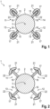
Figur 1 einen Schnitt durch eine erste Ausführungsform einer erfindungsgemäßen Intraokularlinse mit einer Aufspannvorrichtung, die sich in einem nicht aufgespannten Zustand befindet, -
Figur 2 den Schnitt ausFigur 1 , wobei die Aufspannvorrichtung sich in dem aufgespannten Zustand befindet, -
Figur 3 eine Seitenansicht einer zweiten Ausführungsform der Intraokularlinse, -
Figur 4 eine Seitenansicht einer dritten Ausführungsform der Intraokularlinse, -
Figur 5 eine Seitenansicht einer ersten Ausführungsform einer Haptik der Intraokularlinse, -
Figur 6 eine Ansicht von oben auf die erste Ausführungsform der Haptik, -
Figur 7 eine Seitenansicht einer zweiten Ausführungsform einer Haptik der Intraokularlinse, -
Figur 8 eine Ansicht von oben auf die zweite Ausführungsform der Haptik, -
Figur 9 eine Seitenansicht einer dritten Ausführungsform einer Haptik der Intraokularlinse, -
Figur 10 eine Ansicht von oben auf die dritte Ausführungsform der Haptik, -
Figur 11 eine Seitenansicht einer vierten Ausführungsform einer Haptik der Intraokularlinse, -
Figur 12 eine Ansicht von oben auf die vierte Ausführungsform der Haptik. - Wie es aus
Figuren 1 bis 4 ersichtlich ist, weist eine Intraokularlinse 1 einen Optikkörper 2, der eine optische Achse 3 aufweist, und eine Haptik 11 bis 14 auf, die einen Haptikarm 15 und eine Aufspannvorrichtung 21 aufweist. Der Haptikarm 15 ist an dem Optikkörper 2 befestigt sowie weist ein erstes Längsende 16, das dem Optikkörper 2 zugewandt angeordnet ist, und ein zweites Längsende 17 auf, das dem Optikkörper 2 abgewandt angeordnet ist. Die Aufspannvorrichtung 21 ist an dem zweiten Längsende 17 befestigt und weist ein Längsende 22 auf. Die Aufspannvorrichtung 21 hat einen aufgespannten Zustand (sieheFigur 2 ), in dem das Längsende 22 derjenige Teil der Oberfläche der Aufspannvorrichtung 21 ist, der in einer Richtung senkrecht zu einer Radialrichtung 6 bezüglich der optischen Achse 3 am weitesten von dem Haptikarm 15 entfernt ist, und einen nicht aufgespannten Zustand (sieheFigur 2 ), in dem das Längsende 22 in der Richtung senkrecht zu der Radialrichtung 6 weniger weit von dem Haptikarm 15 als in dem aufgespannten Zustand entfernt ist. - Dabei ist denkbar, dass die Aufspannvorrichtung 21 einen Formgedächtniswerkstoff mit einer Übergangstemperatur aufweist und dass die Aufspannvorrichtung 21 eingerichtet ist, durch ein Überschreiten der Übergangstemperatur von dem nicht aufgespannten Zustand in den aufgespannten Zustand zu gelangen. Die Übergangstemperatur kann beispielsweise in einem Bereich von 25°C bis 35°C oder von 30°C bis 35°C liegen. Alternativ ist denkbar, dass die Aufspannvorrichtung 21 einen pseudoelastischen Werkstoff aufweist und dass die Aufspannvorrichtung 21 eingerichtet ist, dass bei Anwenden einer Kraft auf die Aufspannvorrichtung 21 in Richtung zu dem Haptikarm 15 hin die Aufspannvorrichtung 21 von dem aufgespannten Zustand in den nicht aufgespannten Zustand und nach einem Wegfall der Kraft von dem nicht aufgespannten Zustand in den aufgespannten Zustand gelangt.
- Ein Vergleich von
Figur 1 mitFigur 2 zeigt, dass der Formgedächtniswerkstoff eingerichtet sein kann, durch eine Verringerung seiner Krümmung die Aufspannvorrichtung 21 von dem nicht aufgespannten Zustand in den aufgespannten Zustand zu befördern. In analoger Weise kann der pseudoelastische Werkstoff eingerichtet sein, durch eine Verringerung seiner Krümmung die Aufspannvorrichtung 21 von dem nicht aufgespannten Zustand in den aufgespannten Zustand zu befördern. -
Figuren 1 bis 4 zeigen, dass die Intraokularlinse 1 mindestens zwei der Haptiken 11 bis 14 aufweisen kann. Die Haptiken 11 bis 14 können beispielsweise in einer Umfangsrichtung 5 bezüglich der optischen Achse 3 gleichmäßig um den Optikkörper 2 herum angeordnet sein. Es ist denkbar, dass die Anzahl der Haptiken 11 bis 14 gerade ist, insbesondere kann die Anzahl der Haptiken zwei (sieheFigur 3 ) oder vier (sieheFiguren 1, 2 und4 ) sein. - Die Haptikarme 15 können beispielsweise die Form eines Stabes haben, vergleiche
Figuren 1 bis 12 . Insbesondere können die Haptikarme 15 beispielsweise in einer Radialrichtung 6 bezüglich der optischen Achse 3 orientiert sein, vergleicheFigur 3 . Alternativ ist denkbar, dass die Haptikarme 15 zu der optischen Achse 3 hin geneigt sind, vergleicheFigur 4 . Dabei ist denkbar, dass die Haptikarme 15 in der Umfangsrichtung 5 abwechselnd in entgegen gesetzte Richtungen geneigt sind. Dadurch kann der Kapselsack besonders weit aufgespannt werden. -
Figuren 5 bis 12 zeigen verschiedenen Ausführungsformen für die Haptik 11, wobei die Aufspannvorrichtung 21 der Haptik 11 jeweils in dem aufgespannten Zustand dargestellt ist. Die Aufspannvorrichtung 21 kann in dem nicht aufgespannten Zustand sich vollumfänglich um den Haptikarm 15 erstrecken und die Aufspannvorrichtung 21 kann einen Rand 23 aufweisen, der geschlossen ausgebildet ist und in dem aufgespannten Zustand das in der Richtung senkrecht zu der Radialrichtung 6 außenliegende Ende der Aufspannvorrichtung 21 ist, vergleicheFiguren 5 bis 10 . -
Figur 6 zeigt, dass in dem aufgespannten Zustand der Rand 23 die Form eines Kreises haben kann. Der Rand 23 kann symmetrisch zu dem Haptikarm 15 angeordnet sein, so dass das Längsende 22 und der Rand 23 zusammenfallen. - Wie es aus
Figuren 7 bis 12 ersichtlich ist, kann die Aufspannvorrichtung 21 mehrere der Längsenden 22 aufweisen. Beispielsweise kann dabei die Aufspannvorrichtung 21 blütenförmig ausgebildet sein, vergleicheFiguren 7 bis 10 . Dabei weist der Rand 23 in dem aufgespannten Zustand abwechselnd die Längsenden 22 und Minima 24 auf, die in der Richtung senkrecht zu der Radialrichtung 6 weniger weit von dem Haptikarm 15 als die Längsenden 22 entfernt sind. Bei der Ausführungsform gemäßFiguren 9 und 10 sind die Minima 24 deutlich ausgeprägter als bei der Ausführungsform gemäßFiguren 7 und 8 . Der Abstand von dem Haptikarm 15 zu den Minima 24 kann in einem Bereich von 20% bis 90%, bevorzugt von 40% bis 60 %, des Abstandes des Haptikarms 15 zu den Längsenden 22 betragen. -
Figuren 5 bis 12 zeigen, dass der Formgedächtniswerkstoff und/oder der pseudoelastische Werkstoff ein Metall oder eine Legierung aufweisen kann. InFiguren 5 bis 10 ist der Formgedächtniswerkstoff und/oder der pseudoelastische Werkstoff in einen Kunststoff eingebracht. Bei der Ausführungsform der Haptik 11 gemäßFiguren 5 und 6 hat der Formgedächtniswerkstoff und/oder der pseudoelastische Werkstoff die Form eines Rings 25, insbesondere eine Kreisrings. Bei der Ausführungsform der Haptik 11 gemäßFiguren 7 und 8 hat der Formgedächtniswerkstoff und/oder der pseudoelastische Werkstoff eine geschlossene Wellenform 26. Bei den Ausführungsform der Haptik 11 gemäßFiguren 9 bis 12 liegt der Formgedächtniswerkstoff und/oder der pseudoelastische Werkstoff in Form von mehreren Drähten 27 vor. In dem Fall, dass die Anzahl der Längsenden 22 gerade ist, erstreckt sich jeder der Drähte 27 jeweils von einem der Längsenden 22 zu einem anderen der Längsenden 22. In dem Fall, dass die Anzahl der Längsenden 22 ungerade ist, erstreckt sich jeder der Drähte 27 ausgehend von dem zweiten Längsende 17 des Haptikarms 15 bis zu jeweils einem der Längsenden 22. Bei der Ausführungsform gemäßFiguren 11 und 12 ist denkbar, dass der Formgedächtniswerkstoff und/oder der pseudoelastische Werkstoff beschichtet ist, um dadurch eine gute Biokompatibilität zu erreichen. - Alternativ dazu, in den Ausführungsformen gemäß
Figuren 5 bis 12 das Metall oder die Legierung vorzusehen, ist es auch denkbar, dass der Formgedächtniswerkstoff ein Polymer ist. Insbesondere kann die Aufspannvorrichtung aus dem Polymer bestehen. Bei dem Polymer kann es sich beispielsweise um eine Poly(meth)acrylsäure handeln, insbesondere wenn die Intraokularlinse hydrophob ist. Alternativ kann es sich bei dem Polymer um ein 2-Hydoxyethyl-methacrylat und/oder ein 6-Hydroxyhexyl-methacrylat handeln, insbesondere wenn die Intraokularlinse hydrophil ist. -
- 1
- Intraokularlinse
- 2
- Optikkörper
- 3
- optische Achse
- 4
- Axialrichtung
- 5
- Umfangsrichtung
- 6
- Radialrichtung
- 11
- erste Haptik
- 12
- zweite Haptik
- 13
- dritte Haptik
- 14
- vierte Haptik
- 15
- Haptikarm
- 16
- erstes Längsende des Haptikarms
- 17
- zweites Längsende des Haptikarms
- 21
- Aufspannvorrichtung
- 22
- Längsende
- 23
- Rand
- 24
- Minimum
- 25
- Ring
- 26
- geschlossene Wellenform
- 27
- Draht
Claims (9)
- Intraokularlinse mit einem Optikkörper (2), der eine optische Achse (3) aufweist, und einer Haptik (11 bis 14), die einen Haptikarm (15), der an dem Optikkörper (2) befestigt ist sowie ein erstes Längsende (16), das dem Optikkörper (2) zugewandt angeordnet ist, und ein zweites Längsende (17) aufweist, das dem Optikkörper (2) abgewandt angeordnet ist, und eine Aufspannvorrichtung (21) aufweist, die an dem zweiten Längsende (17) befestigt ist, einen Formgedächtniswerkstoff mit einer Übergangstemperatur aufweist und ein Längsende (22) aufweist, wobei die Aufspannvorrichtung (21) einen aufgespannten Zustand, in dem das Längsende (22) derjenige Teil der Oberfläche der Aufspannvorrichtung (21) ist, der in einer Richtung senkrecht zu einer Radialrichtung (6) bezüglich der optischen Achse (3) am weitesten von dem Haptikarm (15) entfernt ist, und einen nicht aufgespannten Zustand hat, in dem das Längsende (22) in der Richtung senkrecht zu der Radialrichtung (6) weniger weit von dem Haptikarm (15) als in dem aufgespannten Zustand entfernt ist, wobei die Aufspannvorrichtung (21) eingerichtet ist, durch ein Überschreiten der Übergangstemperatur von dem nicht aufgespannten Zustand in den aufgespannten Zustand zu gelangen.
- Intraokularlinse gemäß Anspruch 1, wobei der Formgedächtniswerkstoff eingerichtet ist, durch eine Änderung seiner Krümmung die Aufspannvorrichtung (21) von dem nicht aufgespannten Zustand in den aufgespannten Zustand zu befördern.
- Intraokularlinse gemäß Anspruch 1 oder 2, wobei die Übergangstemperatur maximal 35°C und insbesondere mindestens 25°C oder mindestens 30°C beträgt.
- Intraokularlinse gemäß einem der Ansprüche 1 bis 3, wobei der Formgedächtniswerkstoff ein Polymer ist.
- Intraokularlinse gemäß einem der Ansprüche 1 bis 3, wobei der Formgedächtniswerkstoff eine Legierung ist.
- Intraokularlinse mit einem Optikkörper (2), der eine optische Achse (3) aufweist, und einer Haptik (11 bis 14), die einen Haptikarm (15), der an dem Optikkörper (2) befestigt ist sowie ein erstes Längsende (16), das dem Optikkörper (2) zugewandt angeordnet ist, und ein zweites Längsende (17) aufweist, das dem Optikkörper (2) abgewandt angeordnet ist, und eine Aufspannvorrichtung (21) aufweist, die an dem zweiten Längsende (17) befestigt ist, einen pseudoelastischen Werkstoff und ein Längsende (22) aufweist, wobei die Aufspannvorrichtung (21) einen aufgespannten Zustand, in dem das Längsende (22) derjenige Teil der Oberfläche der Aufspannvorrichtung (21) ist, der in einer Richtung senkrecht zu einer Radialrichtung (6) bezüglich der optischen Achse (3) am weitesten von dem Haptikarm (15) entfernt ist, und einen nicht aufgespannten Zustand hat, in dem das Längsende (22) in der Richtung senkrecht zu der Radialrichtung (6) weniger weit von dem Haptikarm (15) als in dem aufgespannten Zustand entfernt ist, wobei die Aufspannvorrichtung (21) eingerichtet ist, dass bei Anwenden einer Kraft auf die Aufspannvorrichtung (21) in Richtung zu dem Haptikarm (15) hin die Aufspannvorrichtung (21) von dem aufgespannten Zustand in den nicht aufgespannten Zustand und nach einem Wegfall der Kraft von dem nicht aufgespannten Zustand in den aufgespannten Zustand gelangt, wobei die Aufspannvorrichtung (21) in dem nicht aufgespannten Zustand sich vollumfänglich um den Haptikarm (15) erstreckt und die Aufspannvorrichtung (21) einen Rand (23) aufweist, der geschlossen ausgebildet ist und in dem aufgespannten Zustand das in der Richtung senkrecht zu der Radialrichtung (6) außenliegende Ende der Aufspannvorrichtung (21) ist.
- Intraokularlinse gemäß Anspruch 6, wobei der pseudoelastische Werkstoff eingerichtet ist, durch eine Änderung seiner Krümmung die Aufspannvorrichtung (21) von dem nicht aufgespannten Zustand in den aufgespannten Zustand zu befördern.
- Intraokularlinse gemäß Anspruch 6 oder 7, wobei in dem aufgespannten Zustand der Rand (23) die Form eines Kreises hat.
- Intraokularlinse gemäß einem der Ansprüche 1 bis 8, wobei die Aufspannvorrichtung (21) mehrere der Längsenden (22) aufweist.
Applications Claiming Priority (1)
| Application Number | Priority Date | Filing Date | Title |
|---|---|---|---|
| DE102022111612.3A DE102022111612B3 (de) | 2022-05-10 | 2022-05-10 | Intraokularlinse mit einer Aufspannvorrichtung |
Publications (2)
| Publication Number | Publication Date |
|---|---|
| EP4275653A1 true EP4275653A1 (de) | 2023-11-15 |
| EP4275653B1 EP4275653B1 (de) | 2026-02-25 |
Family
ID=85795988
Family Applications (1)
| Application Number | Title | Priority Date | Filing Date |
|---|---|---|---|
| EP23169846.5A Active EP4275653B1 (de) | 2022-05-10 | 2023-04-25 | Intraokularlinse mit einer aufspannvorrichtung |
Country Status (2)
| Country | Link |
|---|---|
| EP (1) | EP4275653B1 (de) |
| DE (1) | DE102022111612B3 (de) |
Citations (4)
| Publication number | Priority date | Publication date | Assignee | Title |
|---|---|---|---|---|
| US20050107875A1 (en) * | 1997-05-20 | 2005-05-19 | Eyeonics, Inc. | Accommodating lens with haptics |
| US20100228344A1 (en) | 2002-02-02 | 2010-09-09 | Shadduck John H | Accommodating Intraocular Lens |
| EP2536352B1 (de) * | 2010-02-19 | 2015-02-18 | Luis Olcina Portilla | Akkommodative intraokularlinse |
| EP2846735B1 (de) * | 2012-05-10 | 2022-03-23 | Carl Zeiss Meditec AG | Akkommodative-disakkommodative intraokularlinse |
-
2022
- 2022-05-10 DE DE102022111612.3A patent/DE102022111612B3/de active Active
-
2023
- 2023-04-25 EP EP23169846.5A patent/EP4275653B1/de active Active
Patent Citations (4)
| Publication number | Priority date | Publication date | Assignee | Title |
|---|---|---|---|---|
| US20050107875A1 (en) * | 1997-05-20 | 2005-05-19 | Eyeonics, Inc. | Accommodating lens with haptics |
| US20100228344A1 (en) | 2002-02-02 | 2010-09-09 | Shadduck John H | Accommodating Intraocular Lens |
| EP2536352B1 (de) * | 2010-02-19 | 2015-02-18 | Luis Olcina Portilla | Akkommodative intraokularlinse |
| EP2846735B1 (de) * | 2012-05-10 | 2022-03-23 | Carl Zeiss Meditec AG | Akkommodative-disakkommodative intraokularlinse |
Also Published As
| Publication number | Publication date |
|---|---|
| DE102022111612B3 (de) | 2023-04-27 |
| EP4275653B1 (de) | 2026-02-25 |
Similar Documents
| Publication | Publication Date | Title |
|---|---|---|
| EP1023008B1 (de) | Aufgeweiteter stent und verfahren zum herstellen desselben | |
| DE3348066C2 (de) | ||
| DE69708623T2 (de) | Einteiliges verformbares intraokularlinsenimplantat | |
| DE69507800T2 (de) | Verbesserte gewebestützvorrichtungen | |
| DE2538983A1 (de) | Stuetzsystem fuer kuenstliche intraokulare linsen | |
| DE102010008360A1 (de) | Medizinisches Implantat, in welchem beim Crimpen bzw. Falten Lücken verbleiben, Verfahren und Einrichtung zum Verbringen | |
| EP0481365A1 (de) | Vorrichtung zum Aufweiten einer Stenose in einer Körperröhre | |
| DE112009001492T5 (de) | Akkommodierende intraokulare Linse | |
| EP4275653B1 (de) | Intraokularlinse mit einer aufspannvorrichtung | |
| DE69004871T2 (de) | Intraokularlinse. | |
| DE102011053670A1 (de) | Intraokularlinse | |
| EP4085869B1 (de) | Verfahren zum herstellen einer akkommodativen intraokularlinse | |
| EP4041130B1 (de) | Intraokularlinse mit soll-biegestelle an der haptik | |
| DE10144430A1 (de) | Stent mit variablem Stegquerschnitt | |
| EP3232988B1 (de) | Intraokularlinse mit im optischen teil integrierten einlinsen-teleskop | |
| EP3834776B1 (de) | Intraokularlinse | |
| EP4370063B1 (de) | Injektor mit einer eine mehrzahl an armen aufweisenden kolbenspitze | |
| EP4279028B1 (de) | Intraokularlinse | |
| EP4210631A1 (de) | Akkommodative intraokularlinse | |
| DE4116869C1 (de) | ||
| EP2949291B1 (de) | Intraokularlinse und Mittel zum Herstellen einer Verbindung zwischen einer Intraokularlinse und einem Kapselsack eines Auges | |
| EP4583817B1 (de) | Intraokularlinse mit einer zwei arme aufweisenden ersten haptik und einer zweiten haptik | |
| EP4525780B1 (de) | Intraokularlinse, die einen medikamentenspeicher aufnehmen kann | |
| EP4525781B1 (de) | Medikamentenspeicher für eine intraokularlinse und intraokularlinse mit einem solchen medikamentenspeicher | |
| EP4125717B1 (de) | Intraokularlinse |
Legal Events
| Date | Code | Title | Description |
|---|---|---|---|
| PUAI | Public reference made under article 153(3) epc to a published international application that has entered the european phase |
Free format text: ORIGINAL CODE: 0009012 |
|
| STAA | Information on the status of an ep patent application or granted ep patent |
Free format text: STATUS: THE APPLICATION HAS BEEN PUBLISHED |
|
| AK | Designated contracting states |
Kind code of ref document: A1 Designated state(s): AL AT BE BG CH CY CZ DE DK EE ES FI FR GB GR HR HU IE IS IT LI LT LU LV MC ME MK MT NL NO PL PT RO RS SE SI SK SM TR |
|
| STAA | Information on the status of an ep patent application or granted ep patent |
Free format text: STATUS: REQUEST FOR EXAMINATION WAS MADE |
|
| 17P | Request for examination filed |
Effective date: 20240130 |
|
| RBV | Designated contracting states (corrected) |
Designated state(s): AL AT BE BG CH CY CZ DE DK EE ES FI FR GB GR HR HU IE IS IT LI LT LU LV MC ME MK MT NL NO PL PT RO RS SE SI SK SM TR |
|
| GRAP | Despatch of communication of intention to grant a patent |
Free format text: ORIGINAL CODE: EPIDOSNIGR1 |
|
| STAA | Information on the status of an ep patent application or granted ep patent |
Free format text: STATUS: GRANT OF PATENT IS INTENDED |
|
| INTG | Intention to grant announced |
Effective date: 20251029 |
|
| GRAS | Grant fee paid |
Free format text: ORIGINAL CODE: EPIDOSNIGR3 |
|
| P01 | Opt-out of the competence of the unified patent court (upc) registered |
Free format text: CASE NUMBER: UPC_APP_0015457_4275653/2025 Effective date: 20251202 |
|
| GRAA | (expected) grant |
Free format text: ORIGINAL CODE: 0009210 |
|
| STAA | Information on the status of an ep patent application or granted ep patent |
Free format text: STATUS: THE PATENT HAS BEEN GRANTED |
|
| AK | Designated contracting states |
Kind code of ref document: B1 Designated state(s): AL AT BE BG CH CY CZ DE DK EE ES FI FR GB GR HR HU IE IS IT LI LT LU LV MC ME MK MT NL NO PL PT RO RS SE SI SK SM TR |
|
| REG | Reference to a national code |
Ref country code: CH Ref legal event code: F10 Free format text: ST27 STATUS EVENT CODE: U-0-0-F10-F00 (AS PROVIDED BY THE NATIONAL OFFICE) Effective date: 20260225 Ref country code: GB Ref legal event code: FG4D Free format text: NOT ENGLISH |
|
| REG | Reference to a national code |
Ref country code: DE Ref legal event code: R096 Ref document number: 502023003128 Country of ref document: DE |
|
| REG | Reference to a national code |
Ref country code: IE Ref legal event code: FG4D Free format text: LANGUAGE OF EP DOCUMENT: GERMAN |
|
| REG | Reference to a national code |
Ref country code: NL Ref legal event code: MP Effective date: 20260225 |
|
| PG25 | Lapsed in a contracting state [announced via postgrant information from national office to epo] |
Ref country code: RS Free format text: LAPSE BECAUSE OF FAILURE TO SUBMIT A TRANSLATION OF THE DESCRIPTION OR TO PAY THE FEE WITHIN THE PRESCRIBED TIME-LIMIT Effective date: 20260525 |
|
| PG25 | Lapsed in a contracting state [announced via postgrant information from national office to epo] |
Ref country code: ES Free format text: LAPSE BECAUSE OF FAILURE TO SUBMIT A TRANSLATION OF THE DESCRIPTION OR TO PAY THE FEE WITHIN THE PRESCRIBED TIME-LIMIT Effective date: 20260225 |
|
| PG25 | Lapsed in a contracting state [announced via postgrant information from national office to epo] |
Ref country code: PL Free format text: LAPSE BECAUSE OF FAILURE TO SUBMIT A TRANSLATION OF THE DESCRIPTION OR TO PAY THE FEE WITHIN THE PRESCRIBED TIME-LIMIT Effective date: 20260225 |
|
| PG25 | Lapsed in a contracting state [announced via postgrant information from national office to epo] |
Ref country code: GR Free format text: LAPSE BECAUSE OF FAILURE TO SUBMIT A TRANSLATION OF THE DESCRIPTION OR TO PAY THE FEE WITHIN THE PRESCRIBED TIME-LIMIT Effective date: 20260526 |
|
| REG | Reference to a national code |
Ref country code: LT Ref legal event code: MG9D |
|
| PG25 | Lapsed in a contracting state [announced via postgrant information from national office to epo] |
Ref country code: LT Free format text: LAPSE BECAUSE OF FAILURE TO SUBMIT A TRANSLATION OF THE DESCRIPTION OR TO PAY THE FEE WITHIN THE PRESCRIBED TIME-LIMIT Effective date: 20260225 |
|
| PGFP | Annual fee paid to national office [announced via postgrant information from national office to epo] |
Ref country code: DE Payment date: 20260422 Year of fee payment: 4 |
|
| PG25 | Lapsed in a contracting state [announced via postgrant information from national office to epo] |
Ref country code: NO Free format text: LAPSE BECAUSE OF FAILURE TO SUBMIT A TRANSLATION OF THE DESCRIPTION OR TO PAY THE FEE WITHIN THE PRESCRIBED TIME-LIMIT Effective date: 20260525 |
|
| PG25 | Lapsed in a contracting state [announced via postgrant information from national office to epo] |
Ref country code: FI Free format text: LAPSE BECAUSE OF FAILURE TO SUBMIT A TRANSLATION OF THE DESCRIPTION OR TO PAY THE FEE WITHIN THE PRESCRIBED TIME-LIMIT Effective date: 20260225 Ref country code: SE Free format text: LAPSE BECAUSE OF FAILURE TO SUBMIT A TRANSLATION OF THE DESCRIPTION OR TO PAY THE FEE WITHIN THE PRESCRIBED TIME-LIMIT Effective date: 20260225 |
|
| PGFP | Annual fee paid to national office [announced via postgrant information from national office to epo] |
Ref country code: AT Payment date: 20260714 Year of fee payment: 4 |
|
| PG25 | Lapsed in a contracting state [announced via postgrant information from national office to epo] |
Ref country code: HR Free format text: LAPSE BECAUSE OF FAILURE TO SUBMIT A TRANSLATION OF THE DESCRIPTION OR TO PAY THE FEE WITHIN THE PRESCRIBED TIME-LIMIT Effective date: 20260225 |
|
| PG25 | Lapsed in a contracting state [announced via postgrant information from national office to epo] |
Ref country code: PT Free format text: LAPSE BECAUSE OF FAILURE TO SUBMIT A TRANSLATION OF THE DESCRIPTION OR TO PAY THE FEE WITHIN THE PRESCRIBED TIME-LIMIT Effective date: 20260625 Ref country code: IS Free format text: LAPSE BECAUSE OF FAILURE TO SUBMIT A TRANSLATION OF THE DESCRIPTION OR TO PAY THE FEE WITHIN THE PRESCRIBED TIME-LIMIT Effective date: 20260625 |
|
| PG25 | Lapsed in a contracting state [announced via postgrant information from national office to epo] |
Ref country code: NL Free format text: LAPSE BECAUSE OF FAILURE TO SUBMIT A TRANSLATION OF THE DESCRIPTION OR TO PAY THE FEE WITHIN THE PRESCRIBED TIME-LIMIT Effective date: 20260225 |
|
| PGFP | Annual fee paid to national office [announced via postgrant information from national office to epo] |
Ref country code: FR Payment date: 20260420 Year of fee payment: 4 |
|
| PG25 | Lapsed in a contracting state [announced via postgrant information from national office to epo] |
Ref country code: LV Free format text: LAPSE BECAUSE OF FAILURE TO SUBMIT A TRANSLATION OF THE DESCRIPTION OR TO PAY THE FEE WITHIN THE PRESCRIBED TIME-LIMIT Effective date: 20260225 |
|
| PG25 | Lapsed in a contracting state [announced via postgrant information from national office to epo] |
Ref country code: BG Free format text: LAPSE BECAUSE OF FAILURE TO SUBMIT A TRANSLATION OF THE DESCRIPTION OR TO PAY THE FEE WITHIN THE PRESCRIBED TIME-LIMIT Effective date: 20260225 |