EP4274757B1 - Kompaktantrieb für ein fahrzeug - Google Patents
Kompaktantrieb für ein fahrzeug Download PDFInfo
- Publication number
- EP4274757B1 EP4274757B1 EP21851867.8A EP21851867A EP4274757B1 EP 4274757 B1 EP4274757 B1 EP 4274757B1 EP 21851867 A EP21851867 A EP 21851867A EP 4274757 B1 EP4274757 B1 EP 4274757B1
- Authority
- EP
- European Patent Office
- Prior art keywords
- rotation body
- motor
- drive
- planetary gear
- brake
- Prior art date
- Legal status (The legal status is an assumption and is not a legal conclusion. Google has not performed a legal analysis and makes no representation as to the accuracy of the status listed.)
- Active
Links
Images

Classifications
-
- B—PERFORMING OPERATIONS; TRANSPORTING
- B60—VEHICLES IN GENERAL
- B60K—ARRANGEMENT OR MOUNTING OF PROPULSION UNITS OR OF TRANSMISSIONS IN VEHICLES; ARRANGEMENT OR MOUNTING OF PLURAL DIVERSE PRIME-MOVERS IN VEHICLES; AUXILIARY DRIVES FOR VEHICLES; INSTRUMENTATION OR DASHBOARDS FOR VEHICLES; ARRANGEMENTS IN CONNECTION WITH COOLING, AIR INTAKE, GAS EXHAUST OR FUEL SUPPLY OF PROPULSION UNITS IN VEHICLES
- B60K1/00—Arrangement or mounting of electrical propulsion units
- B60K1/02—Arrangement or mounting of electrical propulsion units comprising more than one electric motor
-
- B—PERFORMING OPERATIONS; TRANSPORTING
- B60—VEHICLES IN GENERAL
- B60K—ARRANGEMENT OR MOUNTING OF PROPULSION UNITS OR OF TRANSMISSIONS IN VEHICLES; ARRANGEMENT OR MOUNTING OF PLURAL DIVERSE PRIME-MOVERS IN VEHICLES; AUXILIARY DRIVES FOR VEHICLES; INSTRUMENTATION OR DASHBOARDS FOR VEHICLES; ARRANGEMENTS IN CONNECTION WITH COOLING, AIR INTAKE, GAS EXHAUST OR FUEL SUPPLY OF PROPULSION UNITS IN VEHICLES
- B60K17/00—Arrangement or mounting of transmissions in vehicles
- B60K17/02—Arrangement or mounting of transmissions in vehicles characterised by arrangement, location, or kind of clutch
-
- B—PERFORMING OPERATIONS; TRANSPORTING
- B60—VEHICLES IN GENERAL
- B60K—ARRANGEMENT OR MOUNTING OF PROPULSION UNITS OR OF TRANSMISSIONS IN VEHICLES; ARRANGEMENT OR MOUNTING OF PLURAL DIVERSE PRIME-MOVERS IN VEHICLES; AUXILIARY DRIVES FOR VEHICLES; INSTRUMENTATION OR DASHBOARDS FOR VEHICLES; ARRANGEMENTS IN CONNECTION WITH COOLING, AIR INTAKE, GAS EXHAUST OR FUEL SUPPLY OF PROPULSION UNITS IN VEHICLES
- B60K17/00—Arrangement or mounting of transmissions in vehicles
- B60K17/04—Arrangement or mounting of transmissions in vehicles characterised by arrangement, location or kind of gearing
- B60K17/06—Arrangement or mounting of transmissions in vehicles characterised by arrangement, location or kind of gearing of change-speed gearing
- B60K17/08—Arrangement or mounting of transmissions in vehicles characterised by arrangement, location or kind of gearing of change-speed gearing of mechanical type
-
- B—PERFORMING OPERATIONS; TRANSPORTING
- B60—VEHICLES IN GENERAL
- B60K—ARRANGEMENT OR MOUNTING OF PROPULSION UNITS OR OF TRANSMISSIONS IN VEHICLES; ARRANGEMENT OR MOUNTING OF PLURAL DIVERSE PRIME-MOVERS IN VEHICLES; AUXILIARY DRIVES FOR VEHICLES; INSTRUMENTATION OR DASHBOARDS FOR VEHICLES; ARRANGEMENTS IN CONNECTION WITH COOLING, AIR INTAKE, GAS EXHAUST OR FUEL SUPPLY OF PROPULSION UNITS IN VEHICLES
- B60K17/00—Arrangement or mounting of transmissions in vehicles
- B60K17/04—Arrangement or mounting of transmissions in vehicles characterised by arrangement, location or kind of gearing
- B60K17/16—Arrangement or mounting of transmissions in vehicles characterised by arrangement, location or kind of gearing of differential gearing
-
- B—PERFORMING OPERATIONS; TRANSPORTING
- B60—VEHICLES IN GENERAL
- B60K—ARRANGEMENT OR MOUNTING OF PROPULSION UNITS OR OF TRANSMISSIONS IN VEHICLES; ARRANGEMENT OR MOUNTING OF PLURAL DIVERSE PRIME-MOVERS IN VEHICLES; AUXILIARY DRIVES FOR VEHICLES; INSTRUMENTATION OR DASHBOARDS FOR VEHICLES; ARRANGEMENTS IN CONNECTION WITH COOLING, AIR INTAKE, GAS EXHAUST OR FUEL SUPPLY OF PROPULSION UNITS IN VEHICLES
- B60K1/00—Arrangement or mounting of electrical propulsion units
- B60K2001/001—Arrangement or mounting of electrical propulsion units one motor mounted on a propulsion axle for rotating right and left wheels of this axle
-
- B—PERFORMING OPERATIONS; TRANSPORTING
- B60—VEHICLES IN GENERAL
- B60Y—INDEXING SCHEME RELATING TO ASPECTS CROSS-CUTTING VEHICLE TECHNOLOGY
- B60Y2304/00—Optimising design; Manufacturing; Testing
- B60Y2304/07—Facilitating assembling or mounting
- B60Y2304/072—Facilitating assembling or mounting by preassembled subunits
-
- B—PERFORMING OPERATIONS; TRANSPORTING
- B60—VEHICLES IN GENERAL
- B60Y—INDEXING SCHEME RELATING TO ASPECTS CROSS-CUTTING VEHICLE TECHNOLOGY
- B60Y2400/00—Special features of vehicle units
- B60Y2400/42—Clutches or brakes
-
- B—PERFORMING OPERATIONS; TRANSPORTING
- B60—VEHICLES IN GENERAL
- B60Y—INDEXING SCHEME RELATING TO ASPECTS CROSS-CUTTING VEHICLE TECHNOLOGY
- B60Y2400/00—Special features of vehicle units
- B60Y2400/70—Gearings
- B60Y2400/73—Planetary gearings
-
- F—MECHANICAL ENGINEERING; LIGHTING; HEATING; WEAPONS; BLASTING
- F16—ENGINEERING ELEMENTS AND UNITS; GENERAL MEASURES FOR PRODUCING AND MAINTAINING EFFECTIVE FUNCTIONING OF MACHINES OR INSTALLATIONS; THERMAL INSULATION IN GENERAL
- F16H—GEARING
- F16H2200/00—Transmissions for multiple ratios
- F16H2200/003—Transmissions for multiple ratios characterised by the number of forward speeds
- F16H2200/0034—Transmissions for multiple ratios characterised by the number of forward speeds the gear ratios comprising two forward speeds
-
- F—MECHANICAL ENGINEERING; LIGHTING; HEATING; WEAPONS; BLASTING
- F16—ENGINEERING ELEMENTS AND UNITS; GENERAL MEASURES FOR PRODUCING AND MAINTAINING EFFECTIVE FUNCTIONING OF MACHINES OR INSTALLATIONS; THERMAL INSULATION IN GENERAL
- F16H—GEARING
- F16H48/00—Differential gearings
- F16H48/06—Differential gearings with gears having orbital motion
- F16H48/08—Differential gearings with gears having orbital motion comprising bevel gears
Definitions
- the invention relates to a compact drive for a vehicle, comprising:
- a frame can also be understood as a housing or a part of a vehicle for example a chassis.
- a drive according to the preamble of claim 1 is known from DE 10 2017 006 266 A1 .
- the known drive requires relatively much installation space.
- An object of the invention is to provide a drive of the type described in the preamble which is compact and robust and with which large transmission ratios can be realized.
- the drive according to the invention is characterized in that the first and third rotation body can be connected to each other by a first clutch, and wherein the first brake and the first clutch are operated simultaneously such that when the first brake is activated, the first clutch is opened and vice versa.
- a brake can here also be understood to mean a coupling that couples the relevant rotation body to the frame (fixed world).
- a dual-motor coupling drive axle comprising a differential and a number of switchable planetary gear sets each having three rotation bodies, wherein the output shafts and the drive shaft of the motor being concentric.
- this drive axle one of the rotation bodies of each planetary gear set is attached to the frame or can be connected to the frame and the other rotation bodies are connected to rotation bodies of neighboring planetary gear sets.
- one of the outputs of the differential passes through the motor which has a hollow drive shaft for this purpose. This results in an even more compact drive.
- the output shafts, the drive shaft electric of the motor and the transmission being concentric. Because the components of the drive are in one line and are concentric, a compact drive can be realized.
- the transmission further comprises two second switchable planetary gear sets, each with three rotation bodies, of the three rotation bodies of each of the second switchable planetary gear sets, a first rotation body is connected to one of the outputs of the differential, a second rotation body is connected to one of the output shafts, and a third rotation body can be connected to the frame via a second brake, wherein the second and third rotation body can be connected to each other by a second coupling, and wherein the second brake and the second clutch are operated simultaneously such that when the second brake is energized, the second clutch is opened and vice versa.
- the transmission is preferably further provided with two final transmissions, each comprising at least one planetary gear set, each planetary gear set has three rotation bodies of which a first rotation body is connected to the second rotation body of one of the second switchable planetary gear units, a second rotation body is connected to one of the output shafts, and a third rotation body is attached to the frame.
- a further embodiment of the compact drive according to the invention is characterized in that the drive comprises a further motor provided with a stator which is attached to the frame and a drive shaft which can be connected via a third coupling to the drive shaft of the motor, both of which motors are concentric.
- the drive comprises a further motor provided with a stator attached to the frame and a drive shaft that can be connected via a third coupling to a third switchable planetary gear set with three rotation bodies.
- a first rotation body is connected to the input of the differential
- a second rotation body is connected to the dive shaft of the motor
- a third rotation body can be connected to the frame via a third brake, whereby the first and third rotation body can be connected to each other are operated by a third clutch, in which the two motors are concentric, and in which the third brake and the third clutch are operated simultaneously such that when the third brake is activated, the third clutch is opened and vice versa.
- the first rotation body of the first switchable planetary gear set and the first rotation body of the third switchable planetary gear set are attached to each other.
- the motor and/or the further motor is an electric motor having a rotor and a stator, wherein the drive shaft being part of the rotor.
- a further embodiment of the compact drive according to the invention is characterized in that the frame is designed like a housing having a cylindrical shape and being closed at both ends by radially extending walls provided with central openings through which the output shafts protrude. This is a compact and robust embodiment of the drive.
- the invention also relates to a vehicle provided with a compact drive according to the invention, which vehicle comprises two driven wheels with two wheel shafts attached thereto which are connected to the output shafts, the housing extending longitudinally between the wheels.
- An embodiment of the vehicle according to the invention is characterized in that the wheel shafts are aligned with and attached to the output shafts.
- the drive is part of the unsprung mass (only sprung from the road by the tires of the wheels).
- a further embodiment of the vehicle according to the invention is characterized in that the wheels are provided with rims and the outer diameter of the housing is smaller than the outer diameter of the rims.
- the construction of the drive according to the invention makes such a compact design possible.
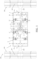
- FIG. 1 shows schematically a part of a first embodiment of the vehicle according to the invention.
- the vehicle 201 is provided with a compact drive designed like an electric drive 1 via which two wheels 203 are driven. Attached to the wheels are wheel axles 205 which are connected via a transmission 9 to two electric motors 5 and 31.
- the transmission 3 has a frame designed like a housing 3 in which the electric motors are present and from which two output shafts 13 protrude that are mounted in end walls 3A of the housing and to which the wheel axles 205 are attached.
- the wheel shafts 205 are in alignment with the output shafts 13.
- the housing 3 extends longitudinally between the wheels 203 and has a cylindrical shape with an outer diameter smaller than that of rims 207 of the wheels 203.
- the electric motors 5 and 31 are attached with their stators 5A and 31A to the housing 3, the rotor 5B of one of the electric motors 5 is connected to the input shaft 11 of the transmission 9.
- the transmission further has a differential 15, with an input 15A, which is connected to the rotor 5B of the electric motor 5, and two outputs 15B which are connected via further transmissions to the output shafts 13.
- the transmission further has a first switchable planetary gear set 17 with three rotation bodies. Of these rotation bodies, a first rotation body 17a is connected to the input 15A of the differential, a second rotation body 17b is connected to the rotor 5B of the electric motor, and a third rotation body 17c can be connected to the housing 3 via a first brake 19.
- the first and third rotation bodies 17a and 17c can be connected to each other by a first clutch 21.
- the first brake 19 and the first clutch 21 are coupled to each other so that they can only be operated simultaneously, wherein when the first brake 19 is energized, the first clutch 21 is opened and vice versa.
- the transmission 9 further has at least two second switchable planetary gear sets 23, which also each have three rotational bodies.
- a first rotation body 23a is connected to one of the outputs 15B of the differential
- a second rotation body 23b is connected to one of the output shafts 13
- a third rotation body 23c can be connected to the housing 3 via a second brake.
- the second and third rotation body 23b and 23c can also be connected to each other by means of a second coupling 27, whereby the second brake 25 and the second coupling 27 can again only be operated simultaneously, wherein if the second brake 25 is energized, the second link 27 is opened and vice versa.
- the outputs 15B of the differential pass through the electric motors 5 and 31, which have a hollow rotor 15B for this purpose, so that the output shafts 13, the electric motors 5 and 31 and the transmission 9 are concentric.
- each second switchable planetary gear set 23 and the associated output shaft 23 there is at least one final transmission formed by a planetary gear set 29 with three rotation bodies, of which a first rotation body 29a is connected to the second rotation body 23b of the second switchable planetary gear assembly 23, a second rotation body 29b is connected to the output shaft 13, and a third rotation body 29c is attached to the housing 3.
- the rotor 31B of the electric motor 31 is connected via a coupling 33 to the rotor 5B of the electric motor 5, so that if only little power is required, the vehicle can be driven with only one electric motor.
- FIG. 2 shows schematically a part of a second embodiment of the vehicle according to the invention. All parts identical to those of the above-described first embodiment are designated with the same reference numerals.
- each electric motor 5 and 131 is located on one side of the differential 15 so that a completely symmetrical construction is obtained.
- the stator 131A of the electric motor is attached to the housing 13.
- the rotor 131B of the electric motor 131 can be connected via a third coupling 133 to a third switchable planetary gear set 135 with three rotation bodies.
- a first rotation body 135a is connected to the differential input 15A and a second rotation body 135b is connected to the rotor 131B of the electric motor.
- a third rotation body 135c can be connected to the housing 3 via a third brake 137 and the first and third rotation bodies 135a and 135c can be connected to each other by a third coupling 139.
- the two electric motors 5 and 131 are also concentric here.
- the third brake 137 and the third clutch 139 can again only be operated simultaneously, such that when the third brake 137 is energized, the third clutch 139 is opened and vice versa.
- the first rotation body 17a of the first switchable planetary gear set 17 and the first rotation body 135a of the third switchable planetary gear set 135 are herein attached to each other.
- the electric drive 1 thus has a housing 3 containing two electric motors 5 and 31 and a transmission 9 provided with a differential 9 via which the electric motors are connected to output shafts 13.
- the transmission 9 has a first switchable planetary gear set 17 located between the differential and the electric motors, and two second switchable planetary gear sets 23 located between the differential and the output shafts.
- One rotation body of these switchable planetary gear sets can be connected to the housing 3 via a brake and can be connected to another of the rotation bodies via a coupling.
- the brake and the clutch can only be operated simultaneously in such a way that when the brake is energized, the clutch is opened and vice versa.
- the output shafts, the electric motors and the transmission are concentric and the housing is cylindrical, so that a compact and robust construction is obtained.
Landscapes
- Engineering & Computer Science (AREA)
- Chemical & Material Sciences (AREA)
- Combustion & Propulsion (AREA)
- Transportation (AREA)
- Mechanical Engineering (AREA)
- Retarders (AREA)
- Connection Of Motors, Electrical Generators, Mechanical Devices, And The Like (AREA)
- Arrangement Or Mounting Of Propulsion Units For Vehicles (AREA)
- Motor Power Transmission Devices (AREA)
- Transmission Devices (AREA)
Claims (13)
- Kompaktantrieb (1; 101) für ein Fahrzeug, umfassend:- einen Rahmen (3),- mindestens einen Motor (5) mit einem am Rahmen (3) befestigten Stator (5A) und einer Antriebswelle (5B),- ein Getriebe (9) mit einer Eingangswelle (11), die mit der Antriebswelle (5B) des Motors (5) verbunden ist, und zwei Ausgangswellen (13), die im Rahmen (3) montiert sind, wobei das Getriebe (9):- ein Differential (15) umfasst mit einem Eingang (15A), der mit der Antriebswelle (5B) des Motors verbunden ist, und zwei Ausgängen (15B), die mit den Ausgangswellen (13) verbunden sind, und- einen ersten schaltbaren Planetenradsatz (17) mit drei Rotationskörpern,- wobei von den drei Rotationskörpern des ersten schaltbaren Planetenradsatzes (17) ein erster Rotationskörper (17a) mit dem Eingang (15A) des Differentials verbunden ist, ein zweiter Rotationskörper (17b) mit der Antriebswelle (5B) verbunden ist des Motors, und ein dritter Rotationskörper (17c) über eine erste Bremse (19) mit dem Rahmen (3) verbunden werden kann, und- die Ausgangswellen (13) und die Antriebswelle des Motors (5) konzentrisch sind, dadurch gekennzeichnet, dass der erste und dritte Rotationskörper (17a, 17c) durch eine erste Kupplung (21) miteinander verbunden werden können, und die erste Bremse (19) und die erste Kupplung (21) gleichzeitig betätigt werden, so dass beim Betätigen der ersten Bremse (19) die erste Kupplung (21) geöffnet wird und umgekehrt.
- Kompaktantrieb (1; 101) nach Anspruch 1, dadurch gekennzeichnet, dass einer der Ausgänge (15B) des Differentials durch den Motor (5) verläuft, der zu diesem Zweck eine hohle Antriebswelle (15B) aufweist.
- Kompaktantrieb (1; 101) nach Anspruch 1 oder 2, dadurch gekennzeichnet, dass die Abtriebswellen (13), der Motor (5) und das Getriebe (9) konzentrisch angeordnet sind.
- Kompaktantrieb (1; 101) nach Anspruch 1, 2 oder 3, dadurch gekennzeichnet, dass das Getriebe (9) weiterhin zwei zweite schaltbare Planetenradsätze (23) mit jeweils drei Rotationskörpern umfasst, wobei von den drei Rotationskörpern jedes der zweiten schaltbaren Planetenradsätze (23) ein erster Rotationskörper (23a) mit einem der Ausgänge (15B) des Differentials verbunden ist, ein zweiter Rotationskörper (23b) mit einer der Ausgangswellen (13) verbunden ist und ein dritter Rotationskörper (23c) über eine zweite Bremse (25) mit dem Rahmen (3) verbindbar ist, wobei der zweite und dritte Rotationskörper (23b, 23c) durch eine zweite Kupplung (27) miteinander verbindbar sind, und wobei die zweite Bremse (25) und die zweite Kupplung (27) gleichzeitig betätigt werden, so dass beim Betätigen der zweiten Bremse (25) die zweite Kupplung (27) geöffnet wird und umgekehrt.
- Kompaktantrieb (1; 101) nach einem der vorhergehenden Ansprüche, dadurch gekennzeichnet, dass das Getriebe (9) weiterhin zwei Planetenradsätze (29) mit jeweils drei Rotationskörpern umfasst, von denen ein erster Rotationskörper (29a) mit dem zweiten Rotationskörper (23b) eines der zweiten schaltbaren Planetenradsätze verbunden ist, ein zweiter Rotationskörper (29b) mit einer der Ausgangswellen (13) verbunden ist und ein dritter Rotationskörper (29c) am Rahmen (3) befestigt ist.
- Kompaktantrieb (1) nach einem der vorhergehenden Ansprüche, dadurch gekennzeichnet, dass der Antrieb einen weiteren Motor (31) umfasst, der mit einem am Rahmen (3) befestigten Stator (31A) und einer Antriebswelle (31B) versehen ist, die über eine dritte Kupplung (33) mit der Antriebswelle (5B) des Motors (5) verbunden werden kann, wobei die beiden Motoren (5, 31) konzentrisch sind.
- Kompaktantrieb (101) nach einem der vorhergehenden Ansprüche 1 bis 5, dadurch gekennzeichnet, dass der Antrieb einen weiteren Motor (131) umfasst, der mit einem am Rahmen (3) befestigten Stator (131A) und einer Antriebswelle (131B) versehen ist, die über eine dritte Kupplung (133) mit einem dritten schaltbaren Planetengetriebe (135) mit drei Rotationskörpern verbunden werden kann, von denen ein erster Rotationskörper (135a) mit dem Eingang (15A) des Differentials verbunden ist, ein zweiter Rotationskörper (135b) mit der Antriebswelle (131B) des Motors verbunden ist und ein dritter Rotationskörper (135c) über eine dritte Bremse (137) mit dem Rahmen (3) verbunden werden kann, wobei der erste und der dritte Rotationskörper (135a, 135c) über eine dritte Kupplung (139) verbunden werden können, wobei die beiden Motoren (5, 131) konzentrisch sind und wobei die dritte Bremse (137) und die dritte Kupplung (139) gleichzeitig betätigt werden, so dass beim Betätigen der dritten Bremse (137) die dritte Kupplung (139) geöffnet wird und umgekehrt.
- Kompaktantrieb (101) nach Anspruch 7, dadurch gekennzeichnet, dass der erste Rotationskörper (17a) des ersten schaltbaren Planetenradsatzes (17) und der erste Rotationskörper (135a) des dritten schaltbaren Planetenradsatzes (135) aneinander befestigt sind.
- Kompaktantrieb (1; 101) nach einem der vorhergehenden Ansprüche, dadurch gekennzeichnet, dass der Motor (5) und/oder der weitere Motor (131) ein Elektromotor mit einem Rotor und einem Stator ist, wobei die Antriebswelle (5B; 131B) Teil des Rotors ist.
- Kompaktantrieb (1; 101) nach einem der vorhergehenden Ansprüche, dadurch gekennzeichnet, dass der Rahmen wie ein Gehäuse (3) ausgebildet ist, das eine zylindrische Form aufweist und an beiden Enden durch radial verlaufende Wände (3A) verschlossen ist, die mit zentralen Öffnungen versehen sind, durch die die Ausgangswellen (13) verlaufen.
- Fahrzeug (201) mit einem Kompaktantrieb (1; 101) nach Anspruch 10, dadurch gekennzeichnet, dass das Fahrzeug (201) zwei angetriebene Räder (203) mit zwei daran befestigten Radachsen (205) umfasst, die mit den Ausgangswellen (13) verbunden sind, wobei sich das Gehäuse (3) in Längsrichtung zwischen den Rädern (203) erstreckt.
- Fahrzeug (201) nach Anspruch 11, dadurch gekennzeichnet, dass die Radwellen (205) ausgerichtet und an den Ausgangswellen (13) befestigt sind.
- Fahrzeug (201) nach Anspruch 11 oder 12, dadurch gekennzeichnet, dass die Räder (203) mit Felgen (207) versehen sind und der Außendurchmesser des Gehäuses (3) kleiner ist als der Außendurchmesser der Felgen (207).
Applications Claiming Priority (2)
| Application Number | Priority Date | Filing Date | Title |
|---|---|---|---|
| PCT/NL2020/050680 WO2022093009A1 (en) | 2020-11-02 | 2020-11-02 | Electric drive for a vehicle |
| PCT/NL2021/050670 WO2022093031A2 (en) | 2020-11-02 | 2021-11-02 | Compact drive for a vehicle |
Publications (3)
| Publication Number | Publication Date |
|---|---|
| EP4274757A2 EP4274757A2 (de) | 2023-11-15 |
| EP4274757C0 EP4274757C0 (de) | 2025-04-02 |
| EP4274757B1 true EP4274757B1 (de) | 2025-04-02 |
Family
ID=74130292
Family Applications (1)
| Application Number | Title | Priority Date | Filing Date |
|---|---|---|---|
| EP21851867.8A Active EP4274757B1 (de) | 2020-11-02 | 2021-11-02 | Kompaktantrieb für ein fahrzeug |
Country Status (3)
| Country | Link |
|---|---|
| US (1) | US11993139B2 (de) |
| EP (1) | EP4274757B1 (de) |
| WO (2) | WO2022093009A1 (de) |
Citations (1)
| Publication number | Priority date | Publication date | Assignee | Title |
|---|---|---|---|---|
| DE102019119949A1 (de) * | 2019-07-24 | 2021-01-28 | Schaeffler Technologies AG & Co. KG | Antriebsvorrichtung für ein Kraftfahrzeug mit drehfester Hohlrad-Sonnenrad- und Planetenradträger-Hohlrad-Bindung |
Family Cites Families (8)
| Publication number | Priority date | Publication date | Assignee | Title |
|---|---|---|---|---|
| US7344469B2 (en) * | 2005-06-28 | 2008-03-18 | Magna Powertrain Usa, Inc. | Torque distributing drive mechanism with ravigneaux gearset |
| CN203567552U (zh) * | 2013-11-29 | 2014-04-30 | 合肥工业大学 | 纯电动汽车用电机-变速器一体化传动系统 |
| DE102014015793A1 (de) * | 2014-10-24 | 2016-04-28 | Audi Ag | Antriebsvorrichtung für ein Kraftfahrzeug, Kraftfahrzeug und Verfahren zum Betrieb eines Kraftfahrzeugs |
| JP6819083B2 (ja) * | 2016-06-13 | 2021-01-27 | 三菱自動車工業株式会社 | トランスアクスル装置 |
| CN106965659B (zh) * | 2017-04-21 | 2023-05-09 | 吉林大学 | 一种带有转矩定向分配功能的双电机耦合驱动桥 |
| DE102017111051B3 (de) * | 2017-05-22 | 2018-06-14 | Schaeffler Technologies AG & Co. KG | Antriebsvorrichtung für ein Kraftfahrzeug |
| DE102017006266A1 (de) * | 2017-07-01 | 2019-01-03 | Daimler Ag | Getriebevorrichtung für einen elektrischen Antrieb eines Kraftfahrzeugs, sowie elektrischer Antrieb für ein Kraftfahrzeug |
| DE102017011401A1 (de) | 2017-12-11 | 2019-06-13 | Daimler Ag | Elektrische Antriebsvorrichtung für ein Kraftfahrzeug |
-
2020
- 2020-11-02 WO PCT/NL2020/050680 patent/WO2022093009A1/en not_active Ceased
-
2021
- 2021-11-02 EP EP21851867.8A patent/EP4274757B1/de active Active
- 2021-11-02 WO PCT/NL2021/050670 patent/WO2022093031A2/en not_active Ceased
- 2021-11-02 US US18/251,472 patent/US11993139B2/en active Active
Patent Citations (1)
| Publication number | Priority date | Publication date | Assignee | Title |
|---|---|---|---|---|
| DE102019119949A1 (de) * | 2019-07-24 | 2021-01-28 | Schaeffler Technologies AG & Co. KG | Antriebsvorrichtung für ein Kraftfahrzeug mit drehfester Hohlrad-Sonnenrad- und Planetenradträger-Hohlrad-Bindung |
Also Published As
| Publication number | Publication date |
|---|---|
| US20240001750A1 (en) | 2024-01-04 |
| WO2022093031A2 (en) | 2022-05-05 |
| EP4274757C0 (de) | 2025-04-02 |
| WO2022093031A3 (en) | 2022-06-09 |
| EP4274757A2 (de) | 2023-11-15 |
| WO2022093009A1 (en) | 2022-05-05 |
| US11993139B2 (en) | 2024-05-28 |
Similar Documents
| Publication | Publication Date | Title |
|---|---|---|
| US9566852B2 (en) | Drive train of an all-electrically drivable motor vehicle with two electric machines | |
| CN113853318B (zh) | 电动车辆的驱动桥 | |
| KR102668478B1 (ko) | 인휠 구동 시스템 및 모터 차량 | |
| US20060046887A1 (en) | Integrated two-speed motor | |
| JP2008501920A (ja) | 遊星差動伝動装置 | |
| CN112752666A (zh) | 用于机动车辆的电驱动桥的驱动装置 | |
| US12409717B2 (en) | Compact E-axle assembly | |
| US12123483B2 (en) | Motor vehicle transmission for an at least partially electrically driven motor vehicle | |
| US20250163997A1 (en) | Electric drive unit for a motor vehicle, in particular for a motor car | |
| CN115704462A (zh) | 用于车辆的传动装置以及具有这种传动装置的传动系 | |
| EP4274757B1 (de) | Kompaktantrieb für ein fahrzeug | |
| US20210252959A1 (en) | Electric solid axle | |
| US12601395B2 (en) | Electric axle drive for an axle of a motor vehicle, in particular of an automobile, and a motor vehicle, in particular an automobile | |
| CN115972879A (zh) | 用于车辆的驱动组件 | |
| US20060118344A1 (en) | Electrically-propelled vehicle with individual wheel drive | |
| CN116691302A (zh) | 动力传动系、电驱动车桥和车辆 | |
| JP2582505B2 (ja) | ハイブリッド型車両 | |
| EP4238802B1 (de) | Verbessertes drehmomentverteilungssystem zwischen achsen eines schwerlastfahrzeugs | |
| JPS59176120A (ja) | 自動車用動力伝達装置 | |
| EP4257401A1 (de) | Verbessertes drehmomentverteilungssystem zwischen achsen eines schwerlastfahrzeugs | |
| EP4257388A1 (de) | Verbessertes drehmomentverteilungssystem zwischen achsen eines schwerlastfahrzeugs | |
| KR102666900B1 (ko) | 변속 시스템 | |
| EP4257389A1 (de) | Verbessertes drehmomentverteilungssystem zwischen achsen eines schwerlastfahrzeugs | |
| US12392401B2 (en) | Transmission for a drive train of a vehicle | |
| KR102592068B1 (ko) | 변속 시스템 |
Legal Events
| Date | Code | Title | Description |
|---|---|---|---|
| STAA | Information on the status of an ep patent application or granted ep patent |
Free format text: STATUS: UNKNOWN |
|
| STAA | Information on the status of an ep patent application or granted ep patent |
Free format text: STATUS: THE INTERNATIONAL PUBLICATION HAS BEEN MADE |
|
| PUAI | Public reference made under article 153(3) epc to a published international application that has entered the european phase |
Free format text: ORIGINAL CODE: 0009012 |
|
| STAA | Information on the status of an ep patent application or granted ep patent |
Free format text: STATUS: REQUEST FOR EXAMINATION WAS MADE |
|
| 17P | Request for examination filed |
Effective date: 20230907 |
|
| AK | Designated contracting states |
Kind code of ref document: A2 Designated state(s): AL AT BE BG CH CY CZ DE DK EE ES FI FR GB GR HR HU IE IS IT LI LT LU LV MC MK MT NL NO PL PT RO RS SE SI SK SM TR |
|
| DAV | Request for validation of the european patent (deleted) | ||
| DAX | Request for extension of the european patent (deleted) | ||
| GRAP | Despatch of communication of intention to grant a patent |
Free format text: ORIGINAL CODE: EPIDOSNIGR1 |
|
| STAA | Information on the status of an ep patent application or granted ep patent |
Free format text: STATUS: GRANT OF PATENT IS INTENDED |
|
| INTG | Intention to grant announced |
Effective date: 20241122 |
|
| GRAS | Grant fee paid |
Free format text: ORIGINAL CODE: EPIDOSNIGR3 |
|
| GRAA | (expected) grant |
Free format text: ORIGINAL CODE: 0009210 |
|
| STAA | Information on the status of an ep patent application or granted ep patent |
Free format text: STATUS: THE PATENT HAS BEEN GRANTED |
|
| AK | Designated contracting states |
Kind code of ref document: B1 Designated state(s): AL AT BE BG CH CY CZ DE DK EE ES FI FR GB GR HR HU IE IS IT LI LT LU LV MC MK MT NL NO PL PT RO RS SE SI SK SM TR |
|
| REG | Reference to a national code |
Ref country code: GB Ref legal event code: FG4D |
|
| REG | Reference to a national code |
Ref country code: CH Ref legal event code: EP |
|
| REG | Reference to a national code |
Ref country code: IE Ref legal event code: FG4D |
|
| REG | Reference to a national code |
Ref country code: DE Ref legal event code: R096 Ref document number: 602021028668 Country of ref document: DE |
|
| U01 | Request for unitary effect filed |
Effective date: 20250501 |
|
| U07 | Unitary effect registered |
Designated state(s): AT BE BG DE DK EE FI FR IT LT LU LV MT NL PT RO SE SI Effective date: 20250508 |
|
| PG25 | Lapsed in a contracting state [announced via postgrant information from national office to epo] |
Ref country code: ES Free format text: LAPSE BECAUSE OF FAILURE TO SUBMIT A TRANSLATION OF THE DESCRIPTION OR TO PAY THE FEE WITHIN THE PRESCRIBED TIME-LIMIT Effective date: 20250402 |
|
| PG25 | Lapsed in a contracting state [announced via postgrant information from national office to epo] |
Ref country code: GR Free format text: LAPSE BECAUSE OF FAILURE TO SUBMIT A TRANSLATION OF THE DESCRIPTION OR TO PAY THE FEE WITHIN THE PRESCRIBED TIME-LIMIT Effective date: 20250703 Ref country code: NO Free format text: LAPSE BECAUSE OF FAILURE TO SUBMIT A TRANSLATION OF THE DESCRIPTION OR TO PAY THE FEE WITHIN THE PRESCRIBED TIME-LIMIT Effective date: 20250702 |
|
| PG25 | Lapsed in a contracting state [announced via postgrant information from national office to epo] |
Ref country code: PL Free format text: LAPSE BECAUSE OF FAILURE TO SUBMIT A TRANSLATION OF THE DESCRIPTION OR TO PAY THE FEE WITHIN THE PRESCRIBED TIME-LIMIT Effective date: 20250402 |
|
| PG25 | Lapsed in a contracting state [announced via postgrant information from national office to epo] |
Ref country code: HR Free format text: LAPSE BECAUSE OF FAILURE TO SUBMIT A TRANSLATION OF THE DESCRIPTION OR TO PAY THE FEE WITHIN THE PRESCRIBED TIME-LIMIT Effective date: 20250402 |
|
| PG25 | Lapsed in a contracting state [announced via postgrant information from national office to epo] |
Ref country code: RS Free format text: LAPSE BECAUSE OF FAILURE TO SUBMIT A TRANSLATION OF THE DESCRIPTION OR TO PAY THE FEE WITHIN THE PRESCRIBED TIME-LIMIT Effective date: 20250702 |
|
| PG25 | Lapsed in a contracting state [announced via postgrant information from national office to epo] |
Ref country code: IS Free format text: LAPSE BECAUSE OF FAILURE TO SUBMIT A TRANSLATION OF THE DESCRIPTION OR TO PAY THE FEE WITHIN THE PRESCRIBED TIME-LIMIT Effective date: 20250802 |
|
| PG25 | Lapsed in a contracting state [announced via postgrant information from national office to epo] |
Ref country code: SM Free format text: LAPSE BECAUSE OF FAILURE TO SUBMIT A TRANSLATION OF THE DESCRIPTION OR TO PAY THE FEE WITHIN THE PRESCRIBED TIME-LIMIT Effective date: 20250402 |
|
| PG25 | Lapsed in a contracting state [announced via postgrant information from national office to epo] |
Ref country code: CZ Free format text: LAPSE BECAUSE OF FAILURE TO SUBMIT A TRANSLATION OF THE DESCRIPTION OR TO PAY THE FEE WITHIN THE PRESCRIBED TIME-LIMIT Effective date: 20250402 |
|
| PG25 | Lapsed in a contracting state [announced via postgrant information from national office to epo] |
Ref country code: SK Free format text: LAPSE BECAUSE OF FAILURE TO SUBMIT A TRANSLATION OF THE DESCRIPTION OR TO PAY THE FEE WITHIN THE PRESCRIBED TIME-LIMIT Effective date: 20250402 |
|
| PLBE | No opposition filed within time limit |
Free format text: ORIGINAL CODE: 0009261 |
|
| STAA | Information on the status of an ep patent application or granted ep patent |
Free format text: STATUS: NO OPPOSITION FILED WITHIN TIME LIMIT |
|
| REG | Reference to a national code |
Ref country code: CH Ref legal event code: L10 Free format text: ST27 STATUS EVENT CODE: U-0-0-L10-L00 (AS PROVIDED BY THE NATIONAL OFFICE) Effective date: 20260211 |
|
| U21 | Renewal fee for the european patent with unitary effect paid with additional fee |
Year of fee payment: 5 Effective date: 20260105 |
|
| 26N | No opposition filed |
Effective date: 20260105 |
|
| PGFP | Annual fee paid to national office [announced via postgrant information from national office to epo] |
Ref country code: GB Payment date: 20260105 Year of fee payment: 5 |