EP4274677B1 - Fluidisierungsapparat und verfahren zur behandlung von partikelförmigen material - Google Patents
Fluidisierungsapparat und verfahren zur behandlung von partikelförmigen material Download PDFInfo
- Publication number
- EP4274677B1 EP4274677B1 EP21844638.3A EP21844638A EP4274677B1 EP 4274677 B1 EP4274677 B1 EP 4274677B1 EP 21844638 A EP21844638 A EP 21844638A EP 4274677 B1 EP4274677 B1 EP 4274677B1
- Authority
- EP
- European Patent Office
- Prior art keywords
- fluidising
- inflow base
- chamber
- inflow
- fluidization
- Prior art date
- Legal status (The legal status is an assumption and is not a legal conclusion. Google has not performed a legal analysis and makes no representation as to the accuracy of the status listed.)
- Active
Links
Images



Classifications
-
- B—PERFORMING OPERATIONS; TRANSPORTING
- B01—PHYSICAL OR CHEMICAL PROCESSES OR APPARATUS IN GENERAL
- B01J—CHEMICAL OR PHYSICAL PROCESSES, e.g. CATALYSIS OR COLLOID CHEMISTRY; THEIR RELEVANT APPARATUS
- B01J8/00—Chemical or physical processes in general, conducted in the presence of fluids and solid particles; Apparatus for such processes
- B01J8/18—Chemical or physical processes in general, conducted in the presence of fluids and solid particles; Apparatus for such processes with fluidised particles
- B01J8/1881—Chemical or physical processes in general, conducted in the presence of fluids and solid particles; Apparatus for such processes with fluidised particles with particles moving downwards while fluidised
-
- B—PERFORMING OPERATIONS; TRANSPORTING
- B01—PHYSICAL OR CHEMICAL PROCESSES OR APPARATUS IN GENERAL
- B01J—CHEMICAL OR PHYSICAL PROCESSES, e.g. CATALYSIS OR COLLOID CHEMISTRY; THEIR RELEVANT APPARATUS
- B01J8/00—Chemical or physical processes in general, conducted in the presence of fluids and solid particles; Apparatus for such processes
- B01J8/0015—Feeding of the particles in the reactor; Evacuation of the particles out of the reactor
- B01J8/002—Feeding of the particles in the reactor; Evacuation of the particles out of the reactor with a moving instrument
-
- B—PERFORMING OPERATIONS; TRANSPORTING
- B01—PHYSICAL OR CHEMICAL PROCESSES OR APPARATUS IN GENERAL
- B01J—CHEMICAL OR PHYSICAL PROCESSES, e.g. CATALYSIS OR COLLOID CHEMISTRY; THEIR RELEVANT APPARATUS
- B01J8/00—Chemical or physical processes in general, conducted in the presence of fluids and solid particles; Apparatus for such processes
- B01J8/0015—Feeding of the particles in the reactor; Evacuation of the particles out of the reactor
- B01J8/003—Feeding of the particles in the reactor; Evacuation of the particles out of the reactor in a downward flow
-
- B—PERFORMING OPERATIONS; TRANSPORTING
- B01—PHYSICAL OR CHEMICAL PROCESSES OR APPARATUS IN GENERAL
- B01J—CHEMICAL OR PHYSICAL PROCESSES, e.g. CATALYSIS OR COLLOID CHEMISTRY; THEIR RELEVANT APPARATUS
- B01J8/00—Chemical or physical processes in general, conducted in the presence of fluids and solid particles; Apparatus for such processes
- B01J8/0015—Feeding of the particles in the reactor; Evacuation of the particles out of the reactor
- B01J8/0035—Periodical feeding or evacuation
-
- B—PERFORMING OPERATIONS; TRANSPORTING
- B01—PHYSICAL OR CHEMICAL PROCESSES OR APPARATUS IN GENERAL
- B01J—CHEMICAL OR PHYSICAL PROCESSES, e.g. CATALYSIS OR COLLOID CHEMISTRY; THEIR RELEVANT APPARATUS
- B01J8/00—Chemical or physical processes in general, conducted in the presence of fluids and solid particles; Apparatus for such processes
- B01J8/08—Chemical or physical processes in general, conducted in the presence of fluids and solid particles; Apparatus for such processes with moving particles
- B01J8/12—Chemical or physical processes in general, conducted in the presence of fluids and solid particles; Apparatus for such processes with moving particles moved by gravity in a downward flow
- B01J8/125—Chemical or physical processes in general, conducted in the presence of fluids and solid particles; Apparatus for such processes with moving particles moved by gravity in a downward flow with multiple sections one above the other separated by distribution aids, e.g. reaction and regeneration sections
-
- B—PERFORMING OPERATIONS; TRANSPORTING
- B01—PHYSICAL OR CHEMICAL PROCESSES OR APPARATUS IN GENERAL
- B01J—CHEMICAL OR PHYSICAL PROCESSES, e.g. CATALYSIS OR COLLOID CHEMISTRY; THEIR RELEVANT APPARATUS
- B01J8/00—Chemical or physical processes in general, conducted in the presence of fluids and solid particles; Apparatus for such processes
- B01J8/18—Chemical or physical processes in general, conducted in the presence of fluids and solid particles; Apparatus for such processes with fluidised particles
- B01J8/1818—Feeding of the fluidising gas
-
- B—PERFORMING OPERATIONS; TRANSPORTING
- B01—PHYSICAL OR CHEMICAL PROCESSES OR APPARATUS IN GENERAL
- B01J—CHEMICAL OR PHYSICAL PROCESSES, e.g. CATALYSIS OR COLLOID CHEMISTRY; THEIR RELEVANT APPARATUS
- B01J8/00—Chemical or physical processes in general, conducted in the presence of fluids and solid particles; Apparatus for such processes
- B01J8/18—Chemical or physical processes in general, conducted in the presence of fluids and solid particles; Apparatus for such processes with fluidised particles
- B01J8/1872—Details of the fluidised bed reactor
-
- B—PERFORMING OPERATIONS; TRANSPORTING
- B01—PHYSICAL OR CHEMICAL PROCESSES OR APPARATUS IN GENERAL
- B01J—CHEMICAL OR PHYSICAL PROCESSES, e.g. CATALYSIS OR COLLOID CHEMISTRY; THEIR RELEVANT APPARATUS
- B01J8/00—Chemical or physical processes in general, conducted in the presence of fluids and solid particles; Apparatus for such processes
- B01J8/18—Chemical or physical processes in general, conducted in the presence of fluids and solid particles; Apparatus for such processes with fluidised particles
- B01J8/24—Chemical or physical processes in general, conducted in the presence of fluids and solid particles; Apparatus for such processes with fluidised particles according to "fluidised-bed" technique
- B01J8/44—Fluidisation grids
-
- F—MECHANICAL ENGINEERING; LIGHTING; HEATING; WEAPONS; BLASTING
- F26—DRYING
- F26B—DRYING SOLID MATERIALS OR OBJECTS BY REMOVING LIQUID THEREFROM
- F26B25/00—Details of general application not covered by group F26B21/00 or F26B23/00
- F26B25/001—Handling, e.g. loading or unloading arrangements
- F26B25/002—Handling, e.g. loading or unloading arrangements for bulk goods
-
- F—MECHANICAL ENGINEERING; LIGHTING; HEATING; WEAPONS; BLASTING
- F26—DRYING
- F26B—DRYING SOLID MATERIALS OR OBJECTS BY REMOVING LIQUID THEREFROM
- F26B3/00—Drying solid materials or objects by processes involving the application of heat
- F26B3/02—Drying solid materials or objects by processes involving the application of heat by convection, i.e. heat being conveyed from a heat source to the materials or objects to be dried by a gas or vapour, e.g. air
- F26B3/06—Drying solid materials or objects by processes involving the application of heat by convection, i.e. heat being conveyed from a heat source to the materials or objects to be dried by a gas or vapour, e.g. air the gas or vapour flowing through the materials or objects to be dried
- F26B3/08—Drying solid materials or objects by processes involving the application of heat by convection, i.e. heat being conveyed from a heat source to the materials or objects to be dried by a gas or vapour, e.g. air the gas or vapour flowing through the materials or objects to be dried so as to loosen them, e.g. to form a fluidised bed
- F26B3/082—Drying solid materials or objects by processes involving the application of heat by convection, i.e. heat being conveyed from a heat source to the materials or objects to be dried by a gas or vapour, e.g. air the gas or vapour flowing through the materials or objects to be dried so as to loosen them, e.g. to form a fluidised bed arrangements of devices for distributing fluidising gas, e.g. grids, nozzles
-
- B—PERFORMING OPERATIONS; TRANSPORTING
- B01—PHYSICAL OR CHEMICAL PROCESSES OR APPARATUS IN GENERAL
- B01J—CHEMICAL OR PHYSICAL PROCESSES, e.g. CATALYSIS OR COLLOID CHEMISTRY; THEIR RELEVANT APPARATUS
- B01J2204/00—Aspects relating to feed or outlet devices; Regulating devices for feed or outlet devices
- B01J2204/005—Aspects relating to feed or outlet devices; Regulating devices for feed or outlet devices the outlet side being of particular interest
-
- B—PERFORMING OPERATIONS; TRANSPORTING
- B01—PHYSICAL OR CHEMICAL PROCESSES OR APPARATUS IN GENERAL
- B01J—CHEMICAL OR PHYSICAL PROCESSES, e.g. CATALYSIS OR COLLOID CHEMISTRY; THEIR RELEVANT APPARATUS
- B01J2208/00—Processes carried out in the presence of solid particles; Reactors therefor
- B01J2208/00743—Feeding or discharging of solids
- B01J2208/00761—Discharging
-
- B—PERFORMING OPERATIONS; TRANSPORTING
- B01—PHYSICAL OR CHEMICAL PROCESSES OR APPARATUS IN GENERAL
- B01J—CHEMICAL OR PHYSICAL PROCESSES, e.g. CATALYSIS OR COLLOID CHEMISTRY; THEIR RELEVANT APPARATUS
- B01J2208/00—Processes carried out in the presence of solid particles; Reactors therefor
- B01J2208/00743—Feeding or discharging of solids
- B01J2208/00769—Details of feeding or discharging
-
- B—PERFORMING OPERATIONS; TRANSPORTING
- B01—PHYSICAL OR CHEMICAL PROCESSES OR APPARATUS IN GENERAL
- B01J—CHEMICAL OR PHYSICAL PROCESSES, e.g. CATALYSIS OR COLLOID CHEMISTRY; THEIR RELEVANT APPARATUS
- B01J2208/00—Processes carried out in the presence of solid particles; Reactors therefor
- B01J2208/00796—Details of the reactor or of the particulate material
- B01J2208/00884—Means for supporting the bed of particles, e.g. grids, bars, perforated plates
-
- B—PERFORMING OPERATIONS; TRANSPORTING
- B01—PHYSICAL OR CHEMICAL PROCESSES OR APPARATUS IN GENERAL
- B01J—CHEMICAL OR PHYSICAL PROCESSES, e.g. CATALYSIS OR COLLOID CHEMISTRY; THEIR RELEVANT APPARATUS
- B01J2208/00—Processes carried out in the presence of solid particles; Reactors therefor
- B01J2208/00796—Details of the reactor or of the particulate material
- B01J2208/00938—Flow distribution elements
Definitions
- the invention relates to a fluidization apparatus for treating particulate material, with a fluidization unit having a longitudinal axis, which has a perforated inflow base dividing the fluidization unit into a distribution chamber and a fluidization chamber arranged above the distribution chamber, wherein the fluidization chamber comprises a material inlet for the material to be treated and the distribution chamber comprises a material outlet for the treated material having a material outlet surface, a lower edge and an upper edge, wherein the inflow base is arranged in an operating position above the upper edge of the material outlet and the distribution chamber comprises a fluid inlet and the fluidization chamber comprises a fluid outlet for a process gas flowing from the fluid inlet through the perforated inflow base to the fluid outlet and fluidizing the material in the fluidization chamber.
- the invention relates to a method for treating particulate material in a fluidization apparatus, with a fluidization unit having a longitudinal axis, which divides the fluidization unit into a Distribution chamber and a perforated inflow floor dividing the fluidization chamber arranged above the distribution chamber, wherein the fluidization chamber comprises a material inlet for the material to be treated and the distribution chamber comprises a material outlet for the treated material having a material outlet surface, a lower edge and an upper edge, wherein the inflow floor is arranged in an operating position above the upper edge of the material outlet and the distribution chamber comprises a fluid inlet and the fluidization chamber comprises a fluid outlet for a process gas flowing from the fluid inlet through the perforated inflow floor to the fluid outlet and fluidizing the material in the fluidization chamber, wherein in an operating state the fluidization chamber is first filled with material to be treated via the material inlet and the material is then treated by the process gas flowing through the fluidization chamber.
- Fluidization apparatus for treating particulate material and in particular fluidized bed apparatus have been known for
- US2004013761 discloses a device for treating particulate material, with a fluidized bed unit which is separated into a process chamber for receiving and treating the material with process air, with a flow plate in the process chamber made of overlapping guide plates, and a distribution chamber which is located below the flow plate.
- a part of the plate is positioned above the upper edge of the material outlet; during treatment, the part of the plate is positioned to close the material outlet by the plate forming a seal with its edge.
- EP 2 611 531 A1 discloses a fluidized bed apparatus for processing particulate material, which comprises a chamber enclosing a distribution chamber, a perforated inflow plate arranged above the distribution chamber, an inlet and an outlet for the process gas and a discharge opening having a lower and an upper edge, defining a height and an opening area, wherein the inflow plate is positioned above the lower edge of the discharge opening such that the opening area of the discharge opening is divided into an opening area below the inflow floor and an opening area above the inflow floor.
- shut-off device such as a flap
- a shut-off device is necessary to close the fluidized bed apparatus, the position of which at the discharge opening requires a complex geometry adapted to the geometry of the fluidized bed apparatus.
- the object of the invention is therefore, on the one hand, to further improve the emptying of a fluidization apparatus with regard to the emptying speed and, on the other hand, to overcome the disadvantages of the prior art.
- the inflow bottom is arranged to be movable relative to the fluidization unit, wherein the inflow bottom is positioned in an emptying position by a movement of the inflow bottom relative to the fluidization unit at least partially below the upper edge of the material outlet, so that a fluid connection is formed between the material outlet arranged in the distribution chamber and the fluidization chamber past the inflow bottom in order to discharge treated material from the fluidization unit.
- the inflow plate In the operating position, the inflow plate is positioned above the upper edge of the material outlet. If the inflow plate is in the operating position, the fluidization apparatus is in the operating state. In the operating position, the material can therefore be treated in the fluidization chamber without material being discharged via the material outlet.
- the inflow plate In the emptying position, the inflow plate is moved relative to the fluidization unit at least partially positioned below the upper edge of the material outlet. If the emptying position is selected, the fluidization device is in the emptying state.
- the inflow plate separates the fluidization chamber and distribution chamber from each other in particular in the operating state.
- the position of the inflow plate in the operating state namely above an upper edge of the material outlet
- sealing the material outlet during the treatment of the particulate material is no longer absolutely necessary.
- the sealing device arranged at the material discharge can therefore be omitted, which leads to a significantly simpler technical design and therefore also results in savings in manufacturing costs.
- the particulate material is fluidized in the fluidization chamber so that the material behaves essentially like a liquid.
- the relative movement between the inflow plate and the fluidization unit allows the particulate material to be emptied via the material discharge after treatment.
- the relative movement can be carried out in such a way that the process gas supports the emptying of the treated material via the material discharge.
- the inflow plate is positioned in the emptying position such that the material outlet surface of the material outlet is divided into a process gas outlet surface below the inflow plate and a material outlet surface above the inflow plate.
- the fluidization unit has a transverse to the longitudinal axis of the fluidization unit Pivoting axis on which the inflow floor is pivotably arranged.
- the pivoting axis expediently runs perpendicular to the central longitudinal axis of the fluidization unit.
- the inflow floor is preferably pivoted around the pivoting axis by an angle between 0° and 60°, expediently by an angle of 5° to 10°.
- the pivoting movement creates an essentially ring-shaped or sickle-shaped gap between the inflow floor and the distribution chamber and/or the fluidization chamber, which must not be too large, since otherwise there is a risk that material treated with process gas can get into the distribution chamber in the emptying state despite the flow through the gap.
- the gap is sealed by the process gas.
- the fluidization unit advantageously has a pivot axis that runs transversely to the longitudinal axis of the fluidization unit and is arranged so that it can be moved in the axial direction of the longitudinal axis, on which the flow plate is arranged so that it can pivot.
- This design of the fluidization apparatus combines the advantages of the two alternative designs of the preferred fluidization apparatus, namely the pivoting and linear movement.
- the gap that forms between the fluidization unit and the flow plate is smaller.
- the inflow base in particular the top side of the inflow base, is positioned flush with the lower edge of the material outlet or at least partially below the lower edge of the material outlet in the emptying position due to the movement of the inflow base relative to the fluidization unit.
- the inflow base in particular the top side of the inflow base, is positioned below the lower edge of the material outlet in the emptying position due to the movement of the inflow base relative to the fluidization unit.
- the material discharge has a shut-off device.
- the material discharge can be closed or opened using the shut-off device. This makes it possible to control the time at which the material discharge is opened.
- the task is also solved in a method of the type mentioned above by determining the operating state of the the inflow base arranged to be movable relative to the fluidization unit is moved into an emptying position such that at least a part of the inflow base is positioned below the upper edge of the material outlet, so that a fluid connection is formed between the material outlet arranged in the distribution chamber and the fluidization chamber past the inflow base and the treated material is discharged from the fluidization unit via the material outlet.
- the inflow plate In the operating position, the inflow plate is positioned above the upper edge of the material outlet. If the inflow plate is in the operating position, the fluidization apparatus is in the operating state. In the operating position, the material can therefore be treated in the fluidization chamber without material being discharged via the material outlet.
- the flow plate In the emptying position, the flow plate is positioned at least partially below the upper edge of the material outlet by a movement of the flow plate relative to the fluidization unit. In the emptying position, the fluidization device is in the emptying state.
- the inflow plate separates the fluidization chamber and distribution chamber from one another in the operating state.
- the position of the inflow plate in the operating state namely above an upper edge of the material outlet
- sealing the material outlet during the treatment of the particulate material is no longer absolutely necessary.
- the sealing device arranged at the material discharge can therefore be omitted, which leads to a significantly simpler technical design and therefore also results in savings in manufacturing costs.
- the relative movement between the inflow plate and the fluidization unit allows the particulate material to be emptied via the material discharge after treatment.
- the relative movement in the form of a pivoting and/or linear movement can be carried out in such a way that the process gas supports the emptying of the treated material via the material discharge.
- the inflow plate is positioned in the emptying position so that the material outlet surface of the material outlet is divided into a process gas outlet surface below the inflow plate and a material outlet surface above the inflow plate.
- the fluidization unit has a pivot axis running transversely to the longitudinal axis of the fluidization unit, on which the inflow base is pivotably arranged and about which the inflow base is pivoted after the treatment of the particulate material, expediently by 5° to 10°.
- This design enables a simple relative movement in the form of a pivoting movement about the pivot axis.
- this opens the material outlet of the material discharge arranged in the distribution chamber for emptying the material treated in the fluidization chamber and, on the other hand, the emptying is promoted by the inclined position of the inflow base.
- the inflow base is preferably pivoted about the pivot axis by an angle between 0° and 60°, expediently by an angle of 5° to 10°. Due to the swivel movement, a substantially crescent-shaped or ring-shaped gap is formed between the inflow floor and the distribution chamber and/or the fluidization chamber, which must not be too large, as otherwise there is a risk that, in the emptying state, despite the flow through the gap, material treated with process gas could be the distribution chamber.
- the process gas conveniently seals the gap in the empty state.
- the inflow floor is arranged to be displaceable in the axial direction of the longitudinal axis and is displaced in the axial direction of the longitudinal axis in the form of a linear movement, expediently until the inflow floor is positioned below the lower edge.
- the inflow floor is preferably displaced in the axial direction of the longitudinal axis.
- the flow plate carries out a pivoting movement and a linear movement when it is brought into the emptying position.
- the flow plate is pivoted around the pivot axis by means of a pivoting movement on the one hand and is moved in the axial direction of the longitudinal axis in the form of a linear movement on the other.
- the pivoting and linear movements can be carried out in any order, one after the other or at the same time. This brings out the advantages of both the pivoting and the linear movement.
- the inflow bottom is moved into the emptying position relative to the fluidization unit such that at least a part of the inflow bottom is positioned below the lower edge of the material outlet.
- the inflow bottom is moved into the emptying position relative to the fluidization unit such that the inflow bottom is positioned below the lower edge of the material outlet.
- the upper edge of the inflow bottom is flush with the lower edge of the material outlet. In both cases, the material outlet area is opened to the maximum so that the treated material can be emptied efficiently and quickly.
- the material discharge has a shut-off device that releases the material discharge as soon as the inflow floor is in the emptying position.
- the shut-off device expediently releases the material discharge as soon as at least part of the inflow floor is positioned below the lower edge of the material outlet.
- Fig.1 shows a plan view of a schematic representation of a first embodiment of the fluidization apparatus 1 designed as a fluidized bed apparatus 2 with a sectional plane AA.
- the fluidization apparatus 1 comprises a fluidization unit 3 having a central longitudinal axis XX on which a discharge pipe 4 is arranged which comprises a central axis YY perpendicular to the longitudinal axis XX.
- the central axis YY and the longitudinal axis XX span the section plane AA.
- the fluidization apparatus 1 is in the operating state.
- sectional plane AA is shown by the schematic representation of the first embodiment of the fluidization apparatus 1 designed as a fluidized bed apparatus 2 in the operating position.
- the fluidization unit 3 comprises a perforated inflow floor 7 which divides the fluidization unit 3 into a distribution chamber 5 and a fluidization chamber 6 arranged above the distribution chamber 5.
- the inflow floor 7 lies in a plane Z-Z spanned perpendicular to the section plane A-A, so that in the operating position, material M to be treated is arranged in the fluidization chamber 6 above the inflow floor 7. If the inflow floor 7 is in the operating position, the fluidization apparatus 1 is in the operating state.
- the fluidization unit 3 of the fluidization apparatus 1 designed as a fluidized bed apparatus 2 is rotationally symmetrical about the central longitudinal axis X-X.
- Other geometric shapes, such as rectangular, in particular square, are realized in other embodiments not shown.
- the distribution chamber 5 has a circular cylindrical shape with a constant distribution chamber inner diameter 9 over a distribution chamber height 8.
- the distribution chamber 5 has a distribution chamber wall 10 spaced radially from the longitudinal axis XX.
- the distribution chamber wall 10 has an inner surface of the distribution chamber wall 10 referred to as the distribution chamber inner wall 11. and an outer surface of the distribution chamber wall 10 referred to as the distribution chamber outer wall 12.
- the fluidization chamber 6 is also circularly cylindrical in the embodiment shown, whereby the fluidization chamber 6, in contrast to the distribution chamber 5, has a conical shape with a fluidization chamber inner diameter 14 that increases from bottom to top over a fluidization chamber height 13.
- the fluidization chamber 6 has a fluidization chamber wall 15 that is radially spaced from the longitudinal axis X-X.
- the fluidization chamber wall 15 has an inner surface of the fluidization chamber wall 15 referred to as the fluidization chamber inner wall 16 and an outer surface of the fluidization chamber wall 15 referred to as the fluidization chamber outer wall 17.
- the fluidization chamber 6 also comprises a material inlet 18 for the material M to be treated and the distribution chamber 5 comprises a material discharge 19 for the treated material M'.
- the material discharge 19 is designed in particular as the discharge pipe 4 having a discharge pipe wall 20, which in the Fig.2 illustrated embodiment is arranged perpendicular to the longitudinal axis XX of the fluidization unit 3 rotationally symmetrical about the central axis YY in the distributor chamber wall 10.
- a material outlet 21 of the material discharge 19 is arranged such that the material outlet 21 is flush with the distributor chamber inner wall 11.
- the material outlet 21 has a material outlet surface 22 and has a lower and an upper edge 23a, 23b for the discharge of the material M' treated in the fluidization chamber 6.
- the distribution chamber 5 has a fluid inlet 24 and the fluidization chamber 6 has a fluid outlet 25.
- the perforated inflow plate 7 In the operating position shown, the perforated inflow plate 7 is arranged in a horizontal position in the plane ZZ, with a process gas PG entering the fluidization unit 3 at the fluid inlet 24 and flowing from the fluid inlet 24 through the perforated inflow plate 7 to the fluid outlet 25, where it exits the fluidization unit 3.
- the perforated inflow plate 7 expediently has passage openings (not shown) for the process gas PG, which generate a pressure loss as it flows through.
- the process gas PG In the operating state, i.e. in the operating position of the inflow plate 7, the process gas PG fluidizes the material M to be treated in the fluidization chamber 6.
- the inflow base 7 is arranged in the fluidization unit 3 so as to be movable relative to the fluidization unit 3.
- the fluidization unit 3 has a pivot axis 26 running transversely to the longitudinal axis XX of the fluidization unit 3, on which the inflow base 7 is pivotably arranged.
- the pivot axis 26 expediently runs perpendicular to the longitudinal axis XX of the fluidization unit 3 and perpendicular to the central axis YY of the discharge pipe 4.
- the inflow floor 7 is arranged above the upper edge 23b. This ensures that during the treatment of the particulate material M by the process gas PG in the fluidization chamber 6, no material M is discharged from the fluidization unit 3 of the fluidization apparatus 1.
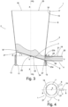
- Fig.3 shows the fluidization apparatus 1 designed as a fluidized bed apparatus 2 in the emptying state.
- the treated material M' is discharged from the fluidization apparatus 1 in the emptying state.
- the inflow plate 7 is moved relative to the fluidization unit 3 in the form of a pivoting movement, so that in the emptying position it is positioned in the fluidization unit 3 pivoted about a pivot axis 26.
- the inflow plate 7 is pivoted by an angle ⁇ about the pivot axis 26 such that at least part of the inflow plate 7 is positioned below the upper edge 23b of the material outlet 21, so that a fluid connection is formed between the material outlet 21 arranged in the distribution chamber 5 and the fluidization chamber 6 past the inflow plate 7 in order to discharge the treated material M' from the fluidization unit 3 via the emptying pipe 4 from the fluidization apparatus 1.
- the inflow plate 7 is expediently pivoted by an angle of 5° to 10°. As a result, the treated material M' flows in the direction of the material outlet.
- the discharge of the treated material M' is supported by the process gas PG, which also flows from the fluid inlet 24 to the fluid outlet 25 through the fluidization unit 3 of the fluidization apparatus 1 in the emptying state. Due to the pivoting movement, a part of the inflow base 7 is preferably positioned below the lower edge 23a. As a result, the material outlet surface 22 of the material outlet 21 is opened as wide as possible, which also promotes an improved discharge of the treated material M'.
- a gap 27 is formed between the inflow plate 7 and the fluidization unit 3, in particular between the inflow plate 7 and the distributor chamber inner wall 11 and/or the fluidization chamber inner wall 16, which gap extends essentially around the entire circumference of the inflow floor 7.
- a gap width formed here varies.
- Process gas PG flows through the gap 27 in the emptying state, so that treated material M' cannot get into or fall into the distribution chamber 5 when discharged from the fluidization chamber 6.
- the inflow floor 7 is positioned in the emptying position such that the material outlet surface 22 of the material outlet 21 is divided into a material outlet partial surface 28 above the inflow floor 7 and a process gas outlet surface 29 below the inflow floor 7.
- FIG.4 is a plan view of a schematic representation of the first embodiment of a fluidization apparatus 1 according to Fig.1 shown, with the fluidization apparatus 1 in the emptying state.
- the inflow floor 7 is arranged in a position pivoted about the pivot axis 26 by the angle ⁇ , whereby the gap 27, which varies in width, is formed between the inflow floor 7 and the fluidization unit 3, in particular the distributor chamber inner wall 11 and/or the fluidization chamber inner wall 16.
- Process gas PG flows through the gap 27 during the emptying process, so that no treated material M' can get into the distributor chamber 5.
- Fig.5 shows accordingly Fig.1 a plan view of a schematic representation of a second embodiment of the fluidization apparatus 1 designed as a fluidized bed apparatus 2 with a sectional plane AA.
- the fluidization apparatus 1 comprises a fluidization unit 3 having a central longitudinal axis XX on which a discharge pipe 4 is arranged which comprises a central axis YY perpendicular to the longitudinal axis XX.
- the central axis YY and the longitudinal axis XX span the section plane AA.
- the fluidization apparatus 1 is in the operating state.
- FIG.6 A section along the section plane AA from Fig.5
- the schematic representation of the second embodiment of the fluidization apparatus 1 in the operating state shows Fig.6 shown.
- the inflow floor 7 lies in a plane ZZ spanning perpendicular to the section plane AA, so that material M to be treated is arranged above the inflow floor 7 in the operating state in the fluidization chamber 6.
- the second embodiment of the fluidization apparatus 1 is essentially identical in construction to the first embodiment of the fluidization apparatus 1.
- the two embodiments differ only in the technical design of the relative movement carried out between the fluidization unit 3 and the inflow plate 7.
- the inflow plate 7 in the second embodiment carries out a linear movement in the axial direction 30 of the longitudinal axis X-X.
- the inflow plate 7 is thus arranged so as to be displaceable in the axial direction 30 of the longitudinal axis X-X.
- a section is made along the section plane AA from Fig.5 by the schematic representation of the second embodiment of the fluidization apparatus 1 with a flow plate 7 arranged in a plane Z'-Z' in a horizontal position, the emptying position.
- the plane Z'-Z' runs parallel to the plane ZZ at a distance d.
- the flow plate 7 is shifted downwards by the distance d in the axial direction 30 of the central longitudinal axis XX, ie from the plane ZZ into the plane Z'-Z'.
- An upper edge 31 is expediently of the inflow floor 7 or an upper side 32 is arranged at the same height as the lower edge 23a of the material outlet 21.
- the upper edge 31 and/or upper side 32 are arranged in particular tangentially to the lower edge 23a of the material outlet 21.
- the material outlet surface 22 of the material outlet 21 is completely open, so that the discharge of treated material M' can be improved.
- Discharge openings 33 are expediently arranged in the perforated inflow floor 7 in the area of the material outlet 21, which are aligned towards the material outlet 21 according to the arrows 34 shown. In this way, the discharge of the treated material M' is additionally supported by the process gas PG in the emptying state.
- Fig.8 shows an enlarged view of the Fig.7 shown section A, which represents the area of the material outlet 21.
- the perforated inflow base 7 has passage openings 35 through which the process gas PG flows in order to fluidize the particulate material M to be treated in the fluidization chamber 6.
- the passage openings can be arranged as desired, the number and diameter of the passage openings 35 being designed according to the specific requirements.
- discharge openings 33 are arranged in the perforated inflow base 7.
- the process gas PG flows in the direction of the arrows 34 through the discharge openings 33 and thus supports efficient and rapid discharge of the treated material M' in the emptying position.
- the upper edge 31 and/or the upper side 32 of the inflow base 7 is cut to the height of the lower edge 23a of the material outlet 21 is lowered flush, whereby the discharge of treated material M' is additionally promoted due to the largest possible material outlet area 22.
- Fig.9 shows a plan view of a schematic representation of a third embodiment of the fluidization apparatus 1 designed as a fluidized bed apparatus 2 with a section plane AA.
- the fluidization apparatus 1 comprises a fluidization unit 3 having a central longitudinal axis XX on which a discharge pipe 4 is arranged which comprises a central axis YY perpendicular to the longitudinal axis XX, the central axis YY and the longitudinal axis XX spanning the section plane AA.
- the fluidization apparatus 1 is in the operating state.
- a section is made along the section plane AA from Fig.9 by the schematic representation of the third embodiment of the fluidization apparatus 1 in the operating state with a flow plate 7 arranged in a plane ZZ in a horizontal position.
- the third embodiment of the fluidization apparatus 1 is essentially a combination of the first two embodiments.
- the inflow base 7 is also movable relative to the fluidization unit 3.
- the inflow base 7 of the third embodiment is suitable for executing a pivoting movement about the pivot axis 26 on the one hand and a linear movement in the axial direction 30 of the longitudinal axis XX on the other.
- the particulate material M is treated in the fluidization chamber 6.
- the swivel and linear movements of the inflow floor when moving it into the emptying position can be carried out in any order, one after the other or simultaneously. This allows the advantages of both the swivel and the linear movement to be realized.
- the material discharge 19 has a shut-off device 36.
- the shut-off device 36 is expediently designed as a flap 37, valve or rotary valve or the like.
- the shut-off device 36 designed as a flap 37 closes the material discharge 19 or opens it.
- the inflow floor 7 is located above the upper edge of the material outlet 21 - the shut-off device 36 closes the material discharge.
- the flap 37 is arranged so as to be pivotable about a pivot axis 38 arranged normal to the central axis YY.
- the particulate material M' treated in the fluidization chamber 6 is discharged from the fluidization unit 3 of the fluidization apparatus 1 via the material discharge 19 designed as a discharge pipe 4.
- the shut-off device 36 is pivoted about the pivot axis 38 and releases the material discharge 19 in the emptying state - the inflow floor is located at least partially below the upper edge of the material outlet 21.
- Fig. 11 shows a section along the section plane AA from Fig.9 by the schematic representation of the third embodiment of the fluidization apparatus 1.
- the inflow floor 7 is pivoted about the pivot axis 26 by an angle ⁇ and on the other hand, the pivot axis 26 is shifted from a plane Z-Z into a plane Z'-Z' aligned parallel to the plane Z-Z in the axial direction 30 of the longitudinal axis X-X.
- the pivot axis 26 of the inflow floor 7 is shifted from a plane Z-Z into a parallel plane Z'-Z' shifted by the distance d and simultaneously pivoting the inflow floor 7 about the pivot axis 26, an improved discharge of the treated material M' from the fluidization chamber 6 is brought about.
- the plane Z'-Z' is arranged below the central axis Y-Y.
- the upper side 32 of the inflow floor 7 is positioned at least partially below the lower edge 23a of the material outlet 21.
- the material discharge 19 having the shut-off device 36 is released by the shut-off device 36 pivoted about the pivot axis 38, so that the treated material M' can be discharged.
Landscapes
- Chemical & Material Sciences (AREA)
- Organic Chemistry (AREA)
- Chemical Kinetics & Catalysis (AREA)
- Engineering & Computer Science (AREA)
- Combustion & Propulsion (AREA)
- Mechanical Engineering (AREA)
- General Engineering & Computer Science (AREA)
- Life Sciences & Earth Sciences (AREA)
- Microbiology (AREA)
- Devices And Processes Conducted In The Presence Of Fluids And Solid Particles (AREA)
- Feeding, Discharge, Calcimining, Fusing, And Gas-Generation Devices (AREA)
Description
- Die Erfindung betrifft einen Fluidisierungsapparat zur Behandlung von partikelförmigem Material, mit einer eine Längsachse aufweisenden Fluidisierungseinheit, die einen die Fluidisierungseinheit in eine Verteilerkammer und eine oberhalb der Verteilerkammer angeordnete Fluidisierungskammer unterteilenden, perforierten Anströmboden aufweist, wobei die Fluidisierungskammer einen Materialeinlass für das zu behandelnde Material und die Verteilerkammer einen über einen eine Materialauslassfläche, eine untere und eine obere Kante aufweisenden Materialauslass für das behandelte Material verfügenden Materialaustrag umfasst, wobei der Anströmboden in einer Betriebsstellung oberhalb der oberen Kante des Materialauslasses angeordnet ist und die Verteilerkammer einen Fluideinlass und die Fluidisierungskammer einen Fluidauslass für ein vom Fluideinlass durch den perforierten Anströmboden zum Fluidauslass strömendes, das Material in der Fluidisierungskammer fluidisierendes Prozessgas umfasst.
- Darüber hinaus betrifft die Erfindung ein Verfahren zur Behandlung von partikelförmigem Material in einem Fluidisierungsapparat, mit einer eine Längsachse aufweisenden Fluidisierungseinheit, die einen die Fluidisierungseinheit in eine Verteilerkammer und eine oberhalb der Verteilerkammer angeordnete Fluidisierungskammer unterteilenden, perforierten Anströmboden aufweist, wobei die Fluidisierungskammer einen Materialeinlass für das zu behandelnde Material und die Verteilerkammer einen über einen eine Materialauslassfläche, eine untere und eine obere Kante aufweisenden Materialauslass für das behandelte Material verfügenden Materialaustrag umfasst, wobei der Anströmboden in einer Betriebsstellung oberhalb der oberen Kante des Materialauslasses angeordnet ist und die Verteilerkammer einen Fluideinlass und die Fluidisierungskammer einen Fluidauslass für ein vom Fluideinlass durch den perforierten Anströmboden zum Fluidauslass strömendes, das Material in der Fluidisierungskammer fluidisierendes Prozessgas umfasst, wobei in einem Betriebszustand zuerst die Fluidisierungskammer über den Materialeinlass mit zu behandelndem Material befüllt und danach das Material durch das durch die Fluidisierungskammer strömende Prozessgas behandelt wird. Fluidisierungsapparate zur Behandlung von partikelförmigem Material und insbesondere Wirbelschichtapparate sind schon seit langem bekannt.
-
US2004013761 offenbart eine Vorrichtung zum Behandeln von partikelförmigem Gut, mit einer Wirbelbetteinheit die getrennt ist in eine Prozesskammer zum Aufnehmen und Behandeln des Gutes mit Prozessluft mit einem Anströmboden in der Prozesskammer aus einander überlappenden Leitplatten, und eine Verteilerkammer die unten den Anströmboden liegt. Zum Entleeren des behandelten Gutes wird ein Teil des Bodens oberhalb der oberen Kante des Materialauslasses positioniert während der Behandlung wird der Teil des Bodens positioniert um den Materialauslass zu schließen, indem der Boden mit dessen Rand eine Dichtung bildet. -
EP 2 611 531 A1 offenbart eine Fließbettapparatur zum Verarbeiten von partikelförmigem Material, die eine eine Verteilerkammer einschließende Kammer, einen perforierte, oberhalb der Verteilerkammer angeordneten Anströmboden, einen Einlass und einen Auslass für das Prozessgas und eine eine untere und einen obere Kante aufweisende, eine Höhe und eine Öffnungsfläche definierende Austragsöffnung umfasst, wobei der Anströmboden oberhalb der unteren Kante der Austragsöffnung derart positioniert ist, dass die Öffnungsfläche der Austragsöffnung in eine Öffnungsfläche unterhalb des Anströmbodens und eine Öffnungsfläche oberhalb des Anströmbodens geteilt ist. - Nachteilig hieran ist, dass eine Absperrvorrichtung, wie bspw. eine Klappe, zum Verschließen der Fließbettapparatur notwendig ist, deren Position an der Austragsöffnung eine komplexe, an die Geometrie der Fließbettapparatur angepasste Geometrie erfordert.
- Aufgabe der Erfindung ist es daher einerseits die Entleerung eines Fluidisierungsapparates in Bezug auf die Entleergeschwindigkeit weiter zu verbessern und andererseits gleichzeitig die Nachteile des Standes der Technik zu überkommen.
- Die Aufgabe wird bei einem Fluidisierungsapparat der eingangs genannten Art dadurch gelöst, dass der Anströmboden relativ zur Fluidisierungseinheit bewegbar angeordnet ist, wobei der Anströmboden in einer Entleerstellung durch eine Bewegung des Anströmbodens relativ zur Fluidisierungseinheit zumindest teilweise unterhalb der oberen Kante des Materialauslasses positioniert ist, sodass sich eine Fluidverbindung zwischen dem in der Verteilerkammer angeordneten Materialauslass und der Fluidisierungskammer am Anströmboden vorbei ausbildet, um behandeltes Material aus der Fluidisierungseinheit auszutragen.
- In der Betriebsstellung ist der Anströmboden oberhalb der oberen Kante des Materialauslasses angeordnet. Ist der Anströmboden in Betriebsstellung befindet sich der Fluidisierungsapparat im Betriebszustand. Somit ist in der Betriebsstellung das Material ohne einen Materialaustrag über den Materialauslass in der Fluidisierungskammer behandelbar.
- In der Entleerstellung ist der Anströmboden durch eine Bewegung des Anströmbodens relativ zur Fluidisierungseinheit zumindest teilweise unterhalb der oberen Kante des Materialauslasses positioniert. Ist der Entleerstellung befindet sich der Fluidisierungsapparat im Entleerzustand.
- Der Anströmboden trennt in dem bevorzugten Fluidisierungsapparat im Betriebszustand insbesondere die Fluidisierungskammer und Verteilerkammer voneinander ab. Somit ist durch die Position des Anströmbodens im Betriebszustand (Betriebsstellung), nämlich oberhalb einer oberen Kante des Materialauslasses, ein Abdichten des Materialauslasses während der Behandlung des partikelförmigen Materials nicht mehr zwingend erforderlich. Die am Materialaustrag angeordnete Abdichtungseinrichtung kann somit entfallen, was konstruktiv zu einer bedeutend einfacheren technischen Ausgestaltung führt und daher auch mit einer Einsparung an Herstellungskosten einhergeht. Das partikelförmige Material wird in der Fluidisierungskammer fluidisiert, sodass sich das Material im Wesentlichen wie eine Flüssigkeit verhält.
- Vorteilhafterweise kann durch die Relativbewegung zwischen Anströmboden und Fluidisierungseinheit das partikelförmige Material nach der Behandlung über den Materialaustrag entleert werden. Die Relativbewegung kann in einer Art und Weise ausgeführt werden, dass das Prozessgas die Entleerung des behandelten Materials über den Materialaustrag unterstützt. In diesem Fall ist der Anströmboden in der Entleerstellung so positioniert, dass die Materialauslassfläche des Materialauslasses in eine Prozessgasauslassfläche unterhalb des Anströmbodens und eine Materialauslassfläche oberhalb des Anströmbodens unterteilt ist.
- Nach einer diesbezüglich vorteilhaften Ausgestaltung des Fluidisierungsapparates weist die Fluidisierungseinheit eine quer zur Längsachse der Fluidisierungseinheit verlaufende Schwenkachse auf, an der der Anströmboden schwenkbar angeordnet ist. Zweckmäßigerweise verläuft die Schwenkachse senkrecht zur zentralen Längsachse der Fluidisierungseinheit. Durch diese Ausführung ist eine einfache Relativbewegung in Form einer Schwenkbewegung um die Schwenkachse möglich. Hierdurch wird zum einen der in der Verteilerkammer angeordnete Materialauslass des Materialaustrags für die Entleerung des in der Fluidisierungskammer behandelten Materials geöffnet und zum anderen wird die Entleerung durch die Schrägstellung des Anströmbodens - wie auch bei Flüssigkeiten - befördert. Überdies wird der Anströmboden bevorzugt um die Schwenkachse um einen Winkel zwischen 0° und 60° geschwenkt, zweckmäßigerweise um einen Winkel von 5° bis 10°. Durch die Schwenkbewegung bildet sich zwischen dem Anströmboden und der Verteilerkammer und/oder der Fluidisierungskammer ein im Wesentlichen ringförmiger oder sichelförmiger Spalt aus, der nicht zu groß werden darf, da hier ansonsten die Gefahr besteht, dass im Entleerzustand trotz der Durchströmung des Spalts mit Prozessgas behandeltes Material in die Verteilerkammer gelangen kann. Prinzipiell wird der Spalt durch das Prozessgas abgedichtet.
- In einer darüber hinaus vorteilhaften hierzu alternativen Ausgestaltung des Fluidisierungsapparates ist der Anströmboden in Achsrichtung der Längsachse verschiebbar angeordnet. Der Anströmboden wird in Achsrichtung der Längsachse in Form einer Linearbewegung verschoben. Zweckmäßigerweise wird der Anströmboden verschoben, bis dessen Oberseite mit der unteren Kante bündig oder unterhalb dieser positioniert ist. Bevorzugt ist der Anströmboden in Achsrichtung der Längsachse verschiebbar angeordnet. Auch durch die alternative Ausgestaltung wird der Materialauslass für eine verbesserte Entleerung nach der Behandlung des partikelförmigen Materials geöffnet.
- Des Weiteren vorteilhaft weist die Fluidisierungseinheit eine quer zur Längsachse der Fluidisierungseinheit verlaufende und in Achsrichtung der Längsachse verschiebbar angeordnete Schwenkachse auf, an der der Anströmboden schwenkbar angeordnet ist. Durch diese Ausgestaltung des Fluidisierungsapparates werden die Vorteile der beiden alternativen Ausgestaltungen des bevorzugten Fluidisierungsapparates, nämlich der Schwenk- und der Linearbewegung, kombiniert. Zudem ist der sich ausbildende Spalt zwischen Fluidisierungseinheit und Anströmboden kleiner.
- Gemäß einer zusätzlichen vorteilhaften Ausbildung des Fluidisierungsapparates ist der Anströmboden, insbesondere die Oberseite des Anströmbodens, in der Entleerstellung durch die Bewegung des Anströmbodens relativ zur Fluidisierungseinheit mit der unteren Kante des Materialauslasses bündig oder zumindest teilweise unterhalb der unteren Kante des Materialauslasses positioniert. Besonders bevorzugt ist der Anströmboden, insbesondere die Oberseite des Anströmbodens, in der Entleerstellung durch die Bewegung des Anströmbodens relativ zur Fluidisierungseinheit unterhalb der unteren Kante des Materialauslasses positioniert. Hierdurch ist die Materialauslassfläche maximal geöffnet, sodass eine Entleerung des behandelten Materials effizient und schnell erfolgen kann.
- Weiter vorteilhaft weist der Materialaustrag eine Absperrvorrichtung auf. Durch die Absperrvorrichtung kann der Materialaustrag verschlossen oder freigegeben werden. Hierdurch besteht die Möglichkeit den Zeitpunkt der Freigabe des Materialaustrages zu steuern.
- Die Aufgabe wird zudem bei einem Verfahren der eingangs genannten Art dadurch gelöst, dass nach dem Betriebszustand der relativ zur Fluidisierungseinheit bewegbar angeordnete Anströmboden derart in eine Entleerstellung bewegt wird, dass zumindest ein Teil des Anströmbodens unterhalb der oberen Kante des Materialauslasses positioniert ist, sodass sich eine Fluidverbindung zwischen dem in der Verteilerkammer angeordneten Materialauslass und der Fluidisierungskammer am Anströmboden vorbei ausbildet und das behandelte Material über den Materialauslass aus der Fluidisierungseinheit ausgetragen wird.
- In der Betriebsstellung ist der Anströmboden oberhalb der oberen Kante des Materialauslasses angeordnet. Ist der Anströmboden in Betriebsstellung befindet sich der Fluidisierungsapparat im Betriebszustand. Somit ist in der Betriebsstellung das Material ohne einen Materialaustrag über den Materialauslass in der Fluidisierungskammer behandelbar.
- In der Entleerstellung ist der Anströmboden durch eine Bewegung des Anströmbodens relativ zur Fluidisierungseinheit zumindest teilweise unterhalb der oberen Kante des Materialauslasses positioniert. Ist der Entleerstellung befindet sich der Fluidisierungsapparat im Entleerzustand.
- Der Anströmboden trennt in dem bevorzugten Fluidisierungsapparat im Betriebszustand die Fluidisierungskammer und Verteilerkammer voneinander ab. Somit ist durch die Position des Anströmbodens im Betriebszustand (Betriebszustand), nämlich oberhalb einer oberen Kante des Materialauslasses, ein Abdichten des Materialauslasses während der Behandlung des partikelförmigen Materials nicht mehr zwingend erforderlich. Die am Materialaustrag angeordnete Abdichtungseinrichtung kann somit entfallen, was konstruktiv zu einer bedeutend einfacheren technischen Ausgestaltung führt und daher auch mit einer Einsparung an Herstellungskosten einhergeht.
- Vorteilhafterweise kann durch die Relativbewegung zwischen Anströmboden und Fluidisierungseinheit das partikelförmige Material nach der Behandlung über den Materialaustrag entleert werden. Die Relativbewegung in Form einer Schwenk- und/oder Linearbewegung kann in einer Art und Weise ausgeführt werden, dass das Prozessgas die Entleerung des behandelten Materials über den Materialaustrag unterstützt. In diesem Fall ist der Anströmboden in der Entleerstellung so positioniert, dass die Materialauslassfläche des Materialauslasses in eine Prozessgasauslassfläche unterhalb des Anströmbodens und eine Materialauslassfläche oberhalb des Anströmbodens unterteilt ist.
- Gemäß einer diesbezüglich vorteilhaften Fortbildung des Verfahrens weist die Fluidisierungseinheit eine quer zur Längsachse der Fluidisierungseinheit verlaufende Schwenkachse auf, an der der Anströmboden schwenkbar angeordnet ist und um die der Anströmboden nach der Behandlung des partikelförmigen Materials geschwenkt wird, zweckmäßigerweise um 5° bis 10°. Durch diese Ausführung ist eine einfache Relativbewegung in Form einer Schwenkbewegung um die Schwenkachse möglich. Hierdurch wird zum einen der in der Verteilerkammer angeordnete Materialauslass des Materialaustrags für die Entleerung des in der Fluidisierungskammer behandelten Materials geöffnet und zum anderen wird die Entleerung durch die Schrägstellung des Anströmbodens befördert. Überdies wird der Anströmboden bevorzugt um die Schwenkachse um einen Winkel zwischen 0° und 60° geschwenkt, zweckmäßigerweise um einen Winkel von 5° bis 10°. Durch die Schwenkbewegung bildet sich zwischen dem Anströmboden und der Verteilerkammer und/oder der Fluidisierungskammer ein im Wesentlichen sichel- oder ringförmiger Spalt aus, der nicht zu groß werden darf, da hier ansonsten die Gefahr besteht, dass im Entleerzustand trotz der Durchströmung des Spalts mit Prozessgas behandeltes Material in die Verteilerkammer gelangen kann. Das Prozessgas dichtet zweckmäßigerweise den Spalt im Entleerzustand ab.
- In einer darüber hinaus vorteilhaften Ausgestaltung des Verfahrens ist der Anströmboden in Achsrichtung der Längsachse verschiebbar angeordnet und wird in Achsrichtung der Längsachse in Form einer Linearbewegung verschoben, zweckmäßigerweise bis der Anströmboden unterhalb der unteren Kante positioniert ist. Bevorzugt wird der Anströmboden in Achsrichtung der Längsachse verschoben. Auch durch die alternative Ausgestaltung wird der Materialauslass für eine verbesserte Entleerung nach der Behandlung des partikelförmigen Materials geöffnet.
- Besonders bevorzugt führt der Anströmboden beim Verbringen in die Entleerstellung eine Schwenkbewegung und eine Linearbewegung aus. Hierbei wird der Anströmboden einerseits mittels einer Schwenkbewegung um die Schwenkachse verschwenkt und andererseits in Achsrichtung der Längsachse in Form einer Linearbewegung verschoben. Die Schenk- und die Linearbewegung können in beliebiger Reihenfolge nacheinander oder zeitgleich zueinander ausgeführt werden. Hierdurch kommen sowohl die Vorteile der Schwenk- als auch der Linearbewegung zum Tragen.
- Entsprechend einer zusätzlichen vorteilhaften Weiterbildung des Verfahrens wird der Anströmboden in die Entleerstellung dergestalt relativ zur Fluidisierungseinheit bewegt, sodass zumindest ein Teil des Anströmbodens unterhalb der unteren Kante des Materialauslasses positioniert ist. Besonders bevorzugt wird der Anströmboden in die Entleerstellung dergestalt relativ zur Fluidisierungseinheit bewegt, sodass der Anströmboden unterhalb der unteren Kante des Materialauslasses positioniert ist. Alternativ ist die obere Kante des Anströmbodens mit der unteren Kante des Materialauslasses bündig angeordnet. In beiden Fällen ist die Materialauslassfläche maximal geöffnet, sodass eine Entleerung des behandelten Materials effizient und schnell erfolgen kann.
- Ein weiterer vorteilhafter Aspekt besteht darin, dass der Materialaustrag eine Absperrvorrichtung aufweist, die den Materialaustrag freigibt, sobald der Anströmboden sich in der Entleerstellung befindet. Zweckmäßigerweise gibt die Absperrvorrichtung den Materialaustrag frei, sobald zumindest ein Teil des Anströmbodens unterhalb der unteren Kante des Materialauslasses positioniert ist. Hierdurch ist die Materialauslassfläche maximal groß geöffnet und das in der Fluidisierungskammer der Fluidisierungseinheit behandelte Material kann effektiv und zeitsparend aus der Fluidisierungseinheit des Fluidisierungsapparates ausgetragen werden.
- Nachfolgend wird die Erfindung anhand der beiliegenden Zeichnung näher erläutert und in dieser zeigen
- Figur 1
- eine Draufsicht auf eine schematische Darstellung einer ersten Ausführungsform eines Fluidisierungsapparates in Betriebsstellung mit einer Schnittebene A-A,
- Figur 2
- einen Schnitt entlang der in
Fig. 1 dargestellten Schnittebene A-A durch die schematische Darstellung der ersten Ausführungsform des Fluidisierungsapparates in Betriebsstellung mit einem auf einer Schwenkachse angeordneten Anströmboden in horizontaler Position, - Figur 3
- einen Schnitt entlang der in
Fig. 1 dargestellten Schnittebene A-A durch die schematische Darstellung der ersten Ausführungsform des Fluidisierungsapparates in Entleerstellung mit dem auf der Schwenkachse angeordneten Anströmboden in einer um einen Winkel α um die Schwenkachse geschwenkten Position, - Figur 4
- eine Draufsicht auf die schematische Darstellung der ersten Ausführungsform des Fluidisierungsapparates in Entleerstellung,
- Figur 5
- eine Draufsicht auf eine schematische Darstellung einer zweiten Ausführungsform eines Fluidisierungsapparates in Betriebsstellung mit einer Schnittebene A-A,
- Figur 6
- einen Schnitt entlang der in
Fig. 5 gezeigten Schnittebene A-A durch die schematische Darstellung der zweiten Ausführungsform des Fluidisierungsapparates in Betriebsstellung mit einem in einer Ebene Z-Z angeordneten Anströmboden in horizontaler Position, - Figur 7
- einen Schnitt entlang der in
Fig. 5 gezeigten Schnittebene A-A durch die schematische Darstellung der zweiten Ausführungsform des Fluidisierungsapparates in Entleerstellung mit dem in einer Ebene Z'-Z' angeordneten Anströmboden in horizontaler Position, - Figur 8
- eine vergrößerte Darstellung des in
Fig. 7 dargestellten Ausschnitts A, - Figur 9
- eine Draufsicht auf eine schematische Darstellung einer dritten Ausführungsform eines Fluidisierungsapparates in Betriebsstellung mit einer Schnittebene A-A,
- Figur 10
- einen Schnitt entlang der Schnittebene A-A aus
Fig. 9 durch die schematische Darstellung der dritten Ausführungsform des Fluidisierungsapparates in Betriebsstellung mit einem in einer Ebene Z-Z angeordneten Anströmboden in horizontaler Position und - Figur 11
- einen Schnitt entlang der Schnittebene A-A aus
Fig. 9 durch die schematische Darstellung der dritten Ausführungsform des Fluidisierungsapparates in Entleerstellung, wobei der Anströmboden in eine Ebene Z'-Z' in Achsrichtung der Längsachse X-X verschobenen und um eine Schwenkachse um einen Winkel α geschwenkt ist. - Sofern keine anderslautenden Angaben gemacht werden, bezieht sich die nachfolgende Beschreibung auf sämtliche in der Zeichnung illustrierten Ausführungsformen eines Fluidisierungsapparates 1 zur Behandlung von partikelförmigem Material M.
-
Fig. 1 zeigt eine Draufsicht auf eine schematische Darstellung einer ersten Ausführungsform des als Wirbelschichtapparat 2 ausgebildeten Fluidisierungsapparates 1 mit einer Schnittebene A-A. Der Fluidisierungsapparat 1 umfasst eine eine zentrale Längsachse X-X aufweisende Fluidisierungseinheit 3 an der ein eine senkrecht zur Längsachse X-X stehende Mittelachse Y-Y umfassendes Entleerrohr 4 angeordnet ist. Die Mittelachse Y-Y und die Längsachse X-X spannen die Schnittebene A-A auf. Der Fluidisierungsapparat 1 befindet sich im Betriebszustand. - In der
Fig. 2 wird ein Schnitt entlang der inFig. 1 gezeigten Schnittebene A-A durch die schematische Darstellung der ersten Ausführungsform des als Wirbelschichtapparat 2 ausgebildeten Fluidisierungsapparates 1 in Betriebsstellung dargestellt. - Die Fluidisierungseinheit 3 umfasst einen die Fluidisierungseinheit 3 in eine Verteilerkammer 5 und eine oberhalb der Verteilerkammer 5 angeordnete Fluidisierungskammer 6 unterteilenden, perforierten Anströmboden 7. Der Anströmboden 7 liegt in Betriebsstellung in einer senkrecht zur Schnittebene A-A aufgespannten Ebene Z-Z, sodass in Betriebsstellung zu behandelndes Material M in der Fluidisierungskammer 6 oberhalb des Anströmbodens 7 angeordnet ist. Ist der Anströmboden 7 in Betriebsstellung befindet sich der Fluidisierungsapparat 1 im Betriebszustand.
- Die Fluidisierungseinheit 3 des als Wirbelschichtapparat 2 ausgebildeten Fluidisierungsapparates 1 ist rotationssymmetrisch um die zentrale Längsachse X-X ausgebildet. Andere geometrische Formen, wie rechteckig, insbesondere quadratisch, sind in anderen nicht gezeigten Ausführungsformen realisiert.
- In der in
Fig. 2 gezeigten Ausführungsform weist die Verteilerkammer 5 eine kreiszylindrische Form mit einem über einer Verteilerkammerhöhe 8 konstanten Verteilerkammer-Innendurchmesser 9 auf. Die Verteilerkammer 5 verfügt über eine radial zur Längsachse X-X beabstandete Verteilerkammerwand 10. Die Verteilerkammerwand 10 weist eine als Verteilerkammerinnenwand 11 bezeichnete Innenfläche der Verteilerkammerwand 10 und eine als Verteilerkammeraußenwand 12 bezeichnete Außenfläche der Verteilerkammerwand 10 auf. - Auch die Fluidisierungskammer 6 ist in der dargestellten Ausführungsform kreiszylindrisch ausgebildet, wobei die Fluidisierungskammer 6 im Gegensatz zur Verteilerkammer 5 eine konische Form mit einem über einer Fluidisierungskammerhöhe 13 von unten nach oben größer werdenden Fluidisierungskammer-Innendurchmesser 14 aufweist. Die Fluidisierungskammer 6 verfügt über eine über eine radial zur Längsachse X-X beabstandete Fluidisierungskammerwand 15. Die Fluidisierungskammerwand 15 weist eine als Fluidisierungskammerinnenwand 16 bezeichnete Innenfläche der Fluidisierungskammerwand 15 und eine als Fluidisierungskammeraußenwand 17 bezeichnete Außenfläche der Fluidisierungskammerwand 15 auf.
- Die Fluidisierungskammer 6 umfasst zudem einen Materialeinlass 18 für das zu behandelnde Material M und die Verteilerkammer 5 einen Materialaustrag 19 für das behandelte Material M'. Der Materialaustrag 19 ist insbesondere als das eine Entleerrohrwand 20 aufweisende Entleerrohr 4 ausgebildet, das in der in
Fig. 2 dargestellten Ausführungsform senkrecht zur Längsachse X-X der Fluidisierungseinheit 3 rotationssymmetrisch um die Mittelachse Y-Y in der Verteilerkammerwand 10 angeordnet ist. Hierbei ist ein Materialauslass 21 des Materialaustrags 19 derart angeordnet, dass der Materialauslass 21 bündig mit der Verteilerkammerinnenwand 11 ausgebildet ist. Der Materialauslass 21 weist eine Materialauslassfläche 22 auf und verfügt über eine untere und eine obere Kante 23a, 23b für den Austrag des in der Fluidisierungskammer 6 behandelten Materials M'. - Darüber hinaus weist die Verteilerkammer 5 einen Fluideinlass 24 und die Fluidisierungskammer 6 einen Fluidauslass 25 auf.
- In der in
Fig. 2 gezeigten Betriebsstellung ist der perforierte Anströmboden 7 in horizontaler Position in der Ebene Z-Z angeordnet, wobei ein Prozessgas PG am Fluideinlass 24 in die Fluidisierungseinheit 3 eintritt und von dem Fluideinlass 24 durch den perforierten Anströmboden 7 zum Fluidauslass 25 strömt, wo es aus der Fluidisierungseinheit 3 austritt. Der perforierte Anströmboden 7 weist zweckmäßigerweise nicht dargestellte Durchtrittsöffnungen für das Prozessgas PG auf, die beim Durchströmen einen Druckverlust erzeugen. Das Prozessgas PG fluidisiert im Betriebszustand, also in der Betriebsstellung des Anströmbodens 7, das zu behandelnde Material M in der Fluidisierungskammer 6. - Der Anströmboden 7 ist in der Fluidisierungseinheit 3 relativ zur Fluidisierungseinheit 3 bewegbar angeordnet. In der in
Fig. 2 gezeigten Ausführungsform des Fluidisierungsapparates 1 weist die Fluidisierungseinheit 3 eine quer zur Längsachse X-X der Fluidisierungseinheit 3 verlaufende Schwenkachse 26 auf, an der der Anströmboden 7 schwenkbar angeordnet ist. In der dargestellten ersten Ausführungsform des Fluidisierungsapparates 1 verläuft die Schwenkachse 26 zweckmäßigerweise senkrecht zur Längsachse X-X der Fluidisierungseinheit 3 und senkrecht zur Mittelachse Y-Y des Entleerrohrs 4. Im inFig. 2 dargestellten Betriebszustand des Fluidisierungsapparates 1 ist der Anströmboden 7 oberhalb der oberen Kante 23b angeordnet. Hierdurch wird sichergestellt, dass während der Behandlung des partikelförmigen Materials M durch das Prozessgas PG in der Fluidisierungskammer 6 kein Material M aus der Fluidisierungseinheit 3 des Fluidisierungsapparates 1 ausgetragen wird. -
Fig. 3 zeigt den als Wirbelschichtapparat 2 ausgebildeten Fluidisierungsapparat 1 im Entleerzustand. Nach der Behandlung des partikelförmigen Materials M im Wirbelschichtapparat 2 wird das behandelte Material M' im Entleerzustand aus dem Fluidisierungsapparat 1 ausgetragen. Hierzu wird der Anströmboden 7 relativ gegenüber der Fluidisierungseinheit 3 in Form einer Schwenkbewegung bewegt, sodass dieser in Entleerstellung um eine Schwenkachse 26 geschwenkt in der Fluidisierungseinheit 3 positioniert ist. In Entleerstellung ist der Anströmboden 7 derart um einem Winkel α um die Schwenkachse 26 geschwenkt, dass zumindest ein Teil des Anströmbodens 7 unterhalb der oberen Kante 23b des Materialauslasses 21 positioniert, sodass sich eine Fluidverbindung zwischen dem in der Verteilerkammer 5 angeordneten Materialauslass 21 und der Fluidisierungskammer 6 am Anströmboden 7 vorbei ausbildet, um das behandelte Material M' aus der Fluidisierungseinheit 3 über das Entleerrohr 4 aus dem Fluidisierungsapparat 1 auszutragen. Zweckmäßigerweise ist der Anströmboden 7 um einen Winkel von 5° bis 10° geschwenkt. Hierdurch fließt das behandelte Material M' in Richtung des Materialauslasses. Unterstützt wird der Austrag des behandelten Materials M' durch das Prozessgas PG, das auch im Entleerzustand vom Fluideinlass 24 zum Fluidauslass 25 durch die Fluidisierungseinheit 3 des Fluidisierungsapparates 1 strömt. Bevorzugt ist aufgrund der Schwenkbewegung ein Teil des Anströmbodens 7 unterhalb der unteren Kante 23a positioniert. Hierdurch wird die Materialauslassfläche 22 des Materialauslasses 21 möglichst weit geöffnet, wodurch zusätzlich ein verbesserter Austrag des behandelten Materials M' befördert wird. - In der Entleerstellung bildet sich aufgrund der Schwenkbewegung durch den um die Schwenkachse 26 geschwenkten Anströmboden 7 ein Spalt 27 zwischen Anströmboden 7 und Fluidisierungseinheit 3, insbesondere zwischen Anströmboden 7 und Verteilerkammerinnenwand 11 und/oder der Fluidisierungskammerinnenwand 16, der sich im Wesentlichen um den gesamten Umfang des Anströmbodens 7 erstreckt. Eine hierbei ausgebildete Spaltbreite variiert. Durch den Spalt 27 strömt im Entleerzustand Prozessgas PG, sodass behandeltes Material M' beim Austrag von der Fluidisierungskammer 6 nicht in die Verteilerkammer 5 gelangen oder fallen kann.
- In der gezeigten Ausführungsform ist der Anströmboden 7 in der Entleerstellung so positioniert, dass die Materialauslassfläche 22 des Materialauslasses 21 in eine Materialauslassteilfläche 28 oberhalb des Anströmbodens 7 und eine Prozessgasauslassfläche 29 unterhalb des Anströmbodens 7 unterteilt ist.
- In der
Fig. 4 wird eine Draufsicht auf eine schematische Darstellung der ersten Ausführungsform eines Fluidisierungsapparates 1 entsprechendFig. 1 gezeigt, wobei sich der Fluidisierungsapparat 1 im Entleerzustand befindet. Hierbei ist der Anströmboden 7 in einer um die Schwenkachse 26 um den Winkel α geschwenkten Position angeordnet, wodurch sich zwischen dem Anströmboden 7 und der Fluidisierungseinheit 3, insbesondere der Verteilerkammerinnenwand 11 und/oder der Fluidisierungskammerinnenwand 16, der in der Spaltbreite variierende Spalt 27 ausbildet. Durch den Spalt 27 strömt während des Entleervorgangs Prozessgas PG, sodass kein behandeltes Material M' in die Verteilerkammer 5 gelangen kann. -
Fig. 5 zeigt entsprechendFig. 1 eine Draufsicht auf eine schematische Darstellung einer zweiten Ausführungsform des als Wirbelschichtapparat 2 ausgebildeten Fluidisierungsapparates 1 mit einer Schnittebene A-A. Der Fluidisierungsapparat 1 umfasst eine eine zentrale Längsachse X-X aufweisende Fluidisierungseinheit 3 an der ein eine senkrecht zur Längsachse X-X stehende Mittelachse Y-Y umfassendes Entleerrohr 4 angeordnet ist. Die Mittelachse Y-Y und die Längsachse X-X spannen die Schnittebene A-A auf. Der Fluidisierungsapparat 1 befindet sich im Betriebszustand. - Ein Schnitt entlang der Schnittebene A-A aus
Fig. 5 durch die schematische Darstellung der zweiten Ausführungsform des sich im Betriebszustand befindenden Fluidisierungsapparates 1 ist inFig. 6 dargestellt. Der Anströmboden 7 liegt in Betriebsstellung in einer senkrecht zur Schnittebene A-A aufgespannten Ebene Z-Z, sodass zu behandelndes Material M im Betriebszustand in der Fluidisierungskammer 6 oberhalb des Anströmbodens 7 angeordnet ist. - Überdies ist die zweite Ausführungsform des Fluidisierungsapparates 1 im Wesentlichen baugleich mit der ersten Ausführungsform des Fluidisierungsapparates 1 ausgebildet. Die beiden Ausführungsformen unterscheiden sich einzig in der technischen Ausführung der zwischen Fluidisierungseinheit 3 und Anströmboden 7 ausgeführten Relativbewegung. Anstelle der Schwenkbewegung - wie in der ersten Ausführungsform - führt der Anströmboden 7 in der zweiten Ausführungsform eine Linearbewegung in Achsrichtung 30 der Längsachse X-X aus. Der Anströmboden 7 ist somit in Achsrichtung 30 der Längsachse X-X verschiebbar angeordnet.
- In
Fig. 7 wird ein Schnitt entlang der Schnittebene A-A ausFig. 5 durch die schematische Darstellung der zweiten Ausführungsform des Fluidisierungsapparates 1 mit einem in einer Ebene Z'-Z' angeordneten Anströmboden 7 in horizontaler Position, der Entleerstellung, gezeigt. Die Ebene Z'-Z' verläuft parallel zur Ebene Z-Z in einem Abstand d. Der Anströmboden 7 ist um den Abstand d in Achsrichtung 30 der zentralen Längsachse X-X nach unten verschoben, d.h. aus der Ebene Z-Z in die Ebene Z'-Z'. Zweckmäßigerweise ist eine obere Kante 31 des Anströmbodens 7 respektive eine Oberseite 32 auf der gleichen Höhe angeordnet wie die untere Kante 23a des Materialauslasses 21. Die obere Kante 31 und/oder Oberseite 32 sind insbesondere tangential an der unteren Kante 23a des Materialauslasses 21 angeordnet. Somit ist die Materialauslassfläche 22 des Materialauslasses 21 vollständig geöffnet, sodass der Austrag an behandelten Material M' verbessert erfolgen kann. - Zweckmäßigerweise sind im perforierten Anströmboden 7 im Bereich des Materialauslasses 21 Austragsöffnungen 33 angeordnet, die entsprechend den dargestellten Pfeilen 34 hin zum Materialauslass 21 ausgerichtet sind. Hierdurch wird im Entleerzustand der Austrag des behandelten Materials M' durch das Prozessgas PG zusätzlich unterstützt.
-
Fig. 8 zeigt eine vergrößerte Darstellung des inFig. 7 dargestellten Ausschnitts A, der den Bereich des Materialauslasses 21 darstellt. Der perforierte Anströmboden 7 weist Durchtrittsöffnungen 35 auf durch die das Prozessgas PG strömt um das zu behandelnde, partikelförmige Material M in der Fluidisierungskammer 6 zu fluidisieren. Die Durchtrittsöffnungen sind beliebig anordenbar, wobei die Durchtrittsöffnungen 35 den spezifischen Anforderungen entsprechend in Anzahl und Durchtrittsöffnungs-Durchmesser ausgebildet sind. Im Bereich des Materialauslasses 21 sind im perforierten Anströmboden 7 Austragsöffnungen 33 angeordnet. Das Prozessgas PG strömt in Richtung der Pfeile 34 durch die Austragsöffnungen 33 und unterstützt so in der Entleerstellung einen effizienten und schnellen Austrag des behandelten Materials M'. Zudem ist die obere Kante 31 und/oder die Oberseite 32 des Anströmbodens 7 bis auf die Höhe der unteren Kante 23a des Materialauslasses 21 bündig abgesenkt, wodurch der Austrag von behandeltem Material M' zusätzlich aufgrund der größtmöglichen Materialauslassfläche 22 gefördert wird. -
Fig. 9 zeigt eine Draufsicht auf eine schematische Darstellung einer dritten Ausführungsform des als Wirbelschichtapparat 2 ausgebildeten Fluidisierungsapparates 1 mit einer Schnittebene A-A. Der Fluidisierungsapparat 1 umfasst eine eine zentrale Längsachse X-X aufweisende Fluidisierungseinheit 3 an der ein eine senkrecht zur Längsachse X-X stehende Mittelachse Y-Y umfassendes Entleerrohr 4 angeordnet ist, wobei die Mittelachse Y-Y und die Längsachse X-X die Schnittebene A-A aufspannen. Der Fluidisierungsapparat 1 befindet sich im Betriebszustand. - In der
Figur 10 wird ein Schnitt entlang der Schnittebene A-A ausFig. 9 durch die schematische Darstellung der dritten Ausführungsform des Fluidisierungsapparates 1 im Betriebszustand mit einem in einer Ebene Z-Z angeordneten Anströmboden 7 in horizontaler Position gezeigt. - Die dritte Ausführungsform des Fluidisierungsapparates 1 ist im Wesentlichen eine Kombination der ersten beiden Ausführungsformen. Auch in der dritten Ausführungsform ist der Anströmboden 7 relativ zu der Fluidisierungseinheit 3 bewegbar. Im Unterschied zur ersten und zweiten Ausführungsform ist der Anströmboden 7 der dritten Ausführungsform geeignet einerseits eine Schwenkbewegung um die Schwenkachse 26 und andererseits eine Linearbewegung in Achsrichtung 30 der Längsachse X-X auszuführen. Im dargestellten Betriebszustand werden das partikelförmigen Material M in der Fluidisierungskammer 6 behandelt.
- Die Schenk- und die Linearbewegung des Anströmbodens beim Verbringen in die Entleerstellung können in beliebiger Reihenfolge nacheinander oder zeitgleich zueinander ausgeführt werden. Hierdurch kommen sowohl die Vorteile der Schwenk- als auch der Linearbewegung zum Tragen.
- Darüber hinaus weist der Materialaustrag 19 eine Absperrvorrichtung 36 auf. Die Absperrvorrichtung 36 ist zweckmäßigerweise als Klappe 37, Ventil oder Zellradschleuse oder dergleichen ausgebildet. Die als Klappe 37 ausgebildete Absperrvorrichtung 36 verschließt den Materialaustrag 19 oder gibt diesen frei. In dem in
Fig. 10 dargestellten Betriebszustand - der Anströmboden 7 befindet sich oberhalb der oberen Kante des Materialauslasses 21 - verschließt die Absperrvorrichtung 36 den Materialaustrag. Somit kann weder Prozessgas PG noch zu behandelndes Material M aus der Fluidisierungseinheit 3 des Fluidisierungsapparates 1 ausströmen oder ausgetragen werden. In der gezeigten Ausführungsform ist die Klappe 37 um eine normal zur Mittelachse Y-Y angeordneten Schwenkachse 38 schwenkbar angeordnet. - Im Entleerzustand wird das in der Fluidisierungskammer 6 behandelte, partikelförmige Material M' aus der Fluidisierungseinheit 3 des Fluidisierungsapparates 1 über den als Entleerrohr 4 ausgebildeten Materialaustrag 19 ausgetragen. Die Absperrvorrichtung 36 ist hierbei um die Schwenkachse 38 verschwenkt und gibt den Materialaustrag 19 im Entleerzustand - der Anströmboden befindet sich zumindest teilweise unterhalb der oberen Kante des Materialauslasses 21 - frei.
-
Fig. 11 zeigt hierzu einen Schnitt entlang der Schnittebene A-A ausFig. 9 durch die schematische Darstellung der dritten Ausführungsform des Fluidisierungsapparates 1. - Der Anströmboden 7 ist zum einen um die Schwenkachse 26 um einen Winkel α geschwenkt und zum anderen ist die Schwenkachse 26 von einer Ebene Z-Z in eine parallel zur Ebene Z-Z ausgerichtete Ebene Z'-Z' in Achsrichtung 30 der Längsachse X-X verschoben. Durch das Absenken der Schwenkachse 26 des Anströmbodens 7 von einer Ebene Z-Z in eine parallele um den Abstand d verschobene Ebene Z'-Z' und das gleichzeitige Schwenken des Anströmbodens 7 um die Schwenkachse 26 wird ein verbesserter Austrag des behandelten Materials M' aus der Fluidisierungskammer 6 bewirkt. In der gezeigten Ausführungsform ist die Ebene Z'-Z' unterhalb der Mittelachse Y-Y angeordnet. Dadurch bedingt, ist es möglich den Winkel α, um den der Anströmboden 7 und die Schwenkachse 26 geschwenkt ist, klein zu halten, sodass der sich zwischen Anströmboden 7 und Fluidisierungseinheit 3 bildende Spalt 27 minimiert wird. Dies führt zu einem weiter verbesserten Austrag.
- Der die Oberseite 32 des Anströmbodens 7 ist in der Entleerstellung zumindest teilweise unterhalb der unteren Kante 23a des Materialauslasses 21 positioniert. Der die Absperrvorrichtung 36 aufweisende Materialaustrag 19 ist von der um die Schwenkachse 38 verschwenkten Absperrvorrichtung 36 freigegeben, sodass das behandelte Material M' ausgetragen werden kann.
Claims (15)
- Fluidisierungsapparat (1) zur Behandlung von partikelförmigem Material (M), mit einer eine Längsachse (X-X) aufweisenden Fluidisierungseinheit (3), die einen die Fluidisierungseinheit (3) in eine Verteilerkammer (5) und eine oberhalb der Verteilerkammer (5) angeordnete Fluidisierungskammer (6) unterteilenden, perforierten Anströmboden (7) aufweist, wobei die Fluidisierungskammer (6) einen Materialeinlass (18) für das zu behandelnde Material (M) und die Verteilerkammer (5) einen über einen eine Materialauslassfläche (22), eine untere und eine obere Kante (23a, 23b) aufweisenden Materialauslass (21) für das behandelte Material (M') verfügenden Materialaustrag (19) umfasst, wobei der Anströmboden (7) in einer Betriebsstellung oberhalb der oberen Kante (23b) des Materialauslasses (21) angeordnet ist und die Verteilerkammer (5) einen Fluideinlass (24) und die Fluidisierungskammer (6) einen Fluidauslass (25) für ein vom Fluideinlass (24) durch den perforierten Anströmboden (7) zum Fluidauslass (25) strömendes, das Material (M) in der Fluidisierungskammer (6) fluidisierendes Prozessgas (PG) umfasst, dadurch gekennzeichnet, dass der Anströmboden (7) relativ zur Fluidisierungseinheit (3) bewegbar angeordnet ist, wobei der Anströmboden (7) in einer Entleerstellung durch eine Bewegung des Anströmbodens (7) relativ zur Fluidisierungseinheit (3) zumindest teilweise unterhalb der oberen Kante (23b) des Materialauslasses (21) positioniert ist, sodass sich eine Fluidverbindung zwischen dem in der Verteilerkammer (5) angeordneten Materialauslass (21) und der Fluidisierungskammer (6) am Anströmboden (7) vorbei ausbildet, um behandeltes Material (M') aus der Fluidisierungseinheit (3) auszutragen.
- Fluidisierungsapparat (1) nach Anspruch 1, dadurch gekennzeichnet, dass die Fluidisierungseinheit (3) eine quer zur Längsachse (X-X) der Fluidisierungseinheit (3) verlaufende Schwenkachse (26) aufweist, an der der Anströmboden (7) schwenkbar angeordnet ist.
- Fluidisierungsapparat (1) nach Anspruch 2, dadurch gekennzeichnet, dass die Schwenkachse (26) senkrecht zur Längsachse (X-X) der Fluidisierungseinheit (3) verläuft.
- Fluidisierungsapparat (1) nach Anspruch 1, dadurch gekennzeichnet, dass der Anströmboden (7) in Achsrichtung (30) der Längsachse (X-X) verschiebbar angeordnet ist.
- Fluidisierungsapparat (1) nach einem der vorhergehenden Ansprüche, dadurch gekennzeichnet, dass die Fluidisierungseinheit (3) eine quer zur Längsachse (X-X) der Fluidisierungseinheit (3) verlaufende und in Achsrichtung (30) der Längsachse (X-X) verschiebbar angeordnete Schwenkachse (26) aufweist, an der der Anströmboden (7) schwenkbar angeordnet ist.
- Fluidisierungsapparat (1) nach einem der vorhergehenden Ansprüche, dadurch gekennzeichnet, dass der Anströmboden (7), insbesondere die Oberseite (32) des Anströmbodens (7), in der Entleerstellung durch die Bewegung des Anströmbodens (7) relativ zur Fluidisierungseinheit (3) mit der unteren Kante des Materialauslasses bündig oder zumindest teilweise unterhalb der unteren Kante (23a) des Materialauslasses (21) positioniert ist.
- Fluidisierungsapparat (1) nach Anspruch 6, dadurch gekennzeichnet, dass der Anströmboden (7), insbesondere die Oberseite (32) des Anströmbodens (7), in der Entleerstellung durch die Bewegung des Anströmbodens (7) relativ zur Fluidisierungseinheit (3) unterhalb der unteren Kante (23a) des Materialauslasses (21) positioniert ist.
- Fluidisierungsapparat (1) nach einem der vorhergehenden Ansprüche, dadurch gekennzeichnet, dass der Materialaustrag (19) eine Absperrvorrichtung (36) aufweist.
- Verfahren zur Behandlung von partikelförmigem Material (M) in einem Fluidisierungsapparat (1), mit einer eine Längsachse (X-X) aufweisenden Fluidisierungseinheit (3), die einen die Fluidisierungseinheit (3) in eine Verteilerkammer (5) und eine oberhalb der Verteilerkammer (5) angeordnete Fluidisierungskammer (6) unterteilenden, perforierten Anströmboden (7) aufweist, wobei die Fluidisierungskammer (6) einen Materialeinlass (18) für das zu behandelnde Material (M) und die Verteilerkammer (5) einen über einen eine Materialauslassfläche (22), eine untere und eine obere Kante (23a, 23b) aufweisenden Materialauslass (21) für das behandelte Material (M') verfügenden Materialaustrag (19) umfasst, wobei der Anströmboden (7) in einer Betriebsstellung oberhalb der oberen Kante (23b) des Materialauslasses (21) angeordnet ist und die Verteilerkammer (5) einen Fluideinlass (24) und die Fluidisierungskammer (6) einen Fluidauslass (25) für ein vom Fluideinlass (24) durch den perforierten Anströmboden (7) zum Fluidauslass (25) strömendes, das Material (M) in der Fluidisierungskammer (6) fluidisierendes Prozessgas (PG) umfasst, wobei in einem Betriebszustand zuerst die Fluidisierungskammer (6) über den Materialeinlass (18) mit zu behandelndem Material (M) befüllt und danach das Material (M) durch das durch die Fluidisierungskammer (6) strömende Prozessgas (PG) behandelt wird, dadurch gekennzeichnet, dass nach dem Betriebszustand der relativ zur Fluidisierungseinheit (3) bewegbar angeordnete Anströmboden (7) derart in eine Entleerstellung bewegt wird, dass zumindest ein Teil des Anströmbodens (7) unterhalb der oberen Kante (23b) des Materialauslasses (21) positioniert ist, sodass sich eine Fluidverbindung zwischen dem in der Verteilerkammer (5) angeordneten Materialauslass (21) und der Fluidisierungskammer (6) am Anströmboden (7) vorbei ausbildet und das behandelte Material (M') über den Materialauslass (21) aus der Fluidisierungseinheit (3) ausgetragen wird.
- Verfahren nach Anspruch 9, dadurch gekennzeichnet, dass die Fluidisierungseinheit (3) eine quer zur Längsachse (X-X) der Fluidisierungseinheit (3) verlaufende Schwenkachse (26) aufweist, an der der Anströmboden (7) schwenkbar angeordnet ist und um die der Anströmboden (7) nach der Behandlung des partikelförmigen Materials (M) geschwenkt wird, zweckmäßigerweise um 5° bis 10°.
- Verfahren nach Anspruch 9, dadurch gekennzeichnet, dass der Anströmboden (7) in Achsrichtung (30) der Längsachse (X-X) verschiebbar angeordnet ist und in Achsrichtung (30) der Längsachse (X-X) in Form einer Linearbewegung verschoben wird, zweckmäßigerweise bis der Anströmboden (7) unterhalb der unteren Kante (23b) positioniert ist.
- Verfahren nach Anspruch 10 und 11, dadurch gekennzeichnet, dass der Anströmboden (7) beim Verbringen in die Entleerstellung eine Schwenkbewegung und eine Linearbewegung ausführt.
- Verfahren nach einem der Ansprüche 9 bis 12, dadurch gekennzeichnet, dass der Anströmboden (7) in die Entleerstellung dergestalt relativ zur Fluidisierungseinheit (3) bewegt wird, sodass zumindest ein Teil des Anströmbodens (7) unterhalb der unteren Kante (23a) des Materialauslasses (21) positioniert ist, wobei zweckmäßigerweise der Anströmboden (7) in die Entleerstellung dergestalt relativ zur Fluidisierungseinheit (3) bewegt wird, sodass der Anströmboden (7) unterhalb der unteren Kante (23a) des Materialauslasses (21) positioniert ist.
- Verfahren nach einem der Ansprüche 9 bis 13, dadurch gekennzeichnet, dass der Materialaustrag (19) eine Absperrvorrichtung (36) aufweist, die den Materialaustrag (19) freigibt, sobald der Anströmboden (7) sich in der Entleerstellung befindet.
- Verfahren nach Anspruch 14, dadurch gekennzeichnet, dass die Absperrvorrichtung (36) den Materialaustrag (19) freigibt, sobald zumindest ein Teil des Anströmbodens (7) unterhalb der unteren Kante (23a) des Materialauslasses (21) positioniert ist.
Applications Claiming Priority (2)
| Application Number | Priority Date | Filing Date | Title |
|---|---|---|---|
| DE102021200161.0A DE102021200161A1 (de) | 2021-01-11 | 2021-01-11 | Fluidisierungsapparat und Verfahren zur Behandlung von partikelförmigen Material |
| PCT/EP2021/086079 WO2022148625A1 (de) | 2021-01-11 | 2021-12-16 | Fluidisierungsapparat und verfahren zur behandlung von partikelförmigen material |
Publications (2)
| Publication Number | Publication Date |
|---|---|
| EP4274677A1 EP4274677A1 (de) | 2023-11-15 |
| EP4274677B1 true EP4274677B1 (de) | 2024-06-26 |
Family
ID=79730444
Family Applications (1)
| Application Number | Title | Priority Date | Filing Date |
|---|---|---|---|
| EP21844638.3A Active EP4274677B1 (de) | 2021-01-11 | 2021-12-16 | Fluidisierungsapparat und verfahren zur behandlung von partikelförmigen material |
Country Status (7)
| Country | Link |
|---|---|
| US (1) | US20240091729A1 (de) |
| EP (1) | EP4274677B1 (de) |
| JP (1) | JP7625706B2 (de) |
| CN (1) | CN117042871A (de) |
| DE (1) | DE102021200161A1 (de) |
| ES (1) | ES2987102T3 (de) |
| WO (1) | WO2022148625A1 (de) |
Families Citing this family (1)
| Publication number | Priority date | Publication date | Assignee | Title |
|---|---|---|---|---|
| DE102021200163A1 (de) * | 2021-01-11 | 2022-07-14 | Glatt Gesellschaft Mit Beschränkter Haftung | Verfahren zur Behandlung von partikelförmigem Material in einem Fluidisierungsapparat |
Family Cites Families (13)
| Publication number | Priority date | Publication date | Assignee | Title |
|---|---|---|---|---|
| DE2421278A1 (de) * | 1973-05-10 | 1974-11-28 | Anhydro As | Apparat zur behandlung fluidisierter materialien |
| DD236006A1 (de) | 1985-04-08 | 1986-05-28 | Stassfurt Veb Chemieanlagenbau | Vorrichtung zum roesten von gekoernten guetern |
| US5115578A (en) | 1991-03-05 | 1992-05-26 | Vector Corporation | Discharge mechanism for a large fluid bed/dryer granulator |
| JPH07265683A (ja) * | 1994-04-01 | 1995-10-17 | Freunt Ind Co Ltd | 流動層装置および粉粒体の造粒、コーティング、乾燥方法 |
| BR9906717A (pt) * | 1998-11-02 | 2000-10-17 | Kawasaki Jugogyo Kabushiki Kai | Equipamento de classificação de leito fluidizado de multi-câmaras |
| DE10054557C2 (de) * | 2000-10-31 | 2003-11-13 | Herbert Huettlin | Vorrichtung zum Behandeln von partikelförmigem Gut |
| CN2779321Y (zh) * | 2005-03-09 | 2006-05-10 | 李安民 | 流化床式粮食烘干设备 |
| WO2012028894A1 (en) | 2010-08-30 | 2012-03-08 | Gea, Pharma Systems Ag | Fluid bed apparatus and method for processing a particulate material |
| DE102013005921A1 (de) * | 2013-04-03 | 2014-10-09 | Glatt Ingenieurtechnik Gmbh | Fluidisierungsapparat |
| ES2745476T3 (es) * | 2013-04-03 | 2020-03-02 | Glatt Ingtech Gmbh | Procedimiento para el tratamiento de partículas sólidas |
| FR3063231B1 (fr) * | 2017-02-27 | 2021-09-17 | Total Raffinage Chimie | Element d'injection de gaz pour unite de craquage catalytique fluide et systeme de distribution de gaz equipe de cet element d'injection. |
| DE102017109951A1 (de) * | 2017-05-09 | 2018-11-15 | Glatt Maschinen- Und Apparatebau Ag | Vorrichtung und Verfahren zum Granulieren, Agglomerieren, Pelletieren, Trocknen und/oder Coaten |
| DE102018103801A1 (de) * | 2018-02-20 | 2019-02-21 | Thyssenkrupp Ag | Wirbelschicht-Sprühgranulator und Verfahren zur Sprühgranulation |
-
2021
- 2021-01-11 DE DE102021200161.0A patent/DE102021200161A1/de not_active Withdrawn
- 2021-12-16 JP JP2023541736A patent/JP7625706B2/ja active Active
- 2021-12-16 US US18/260,912 patent/US20240091729A1/en active Pending
- 2021-12-16 EP EP21844638.3A patent/EP4274677B1/de active Active
- 2021-12-16 CN CN202180089997.0A patent/CN117042871A/zh active Pending
- 2021-12-16 WO PCT/EP2021/086079 patent/WO2022148625A1/de not_active Ceased
- 2021-12-16 ES ES21844638T patent/ES2987102T3/es active Active
Also Published As
| Publication number | Publication date |
|---|---|
| JP2024502186A (ja) | 2024-01-17 |
| EP4274677A1 (de) | 2023-11-15 |
| CN117042871A (zh) | 2023-11-10 |
| ES2987102T3 (es) | 2024-11-13 |
| WO2022148625A1 (de) | 2022-07-14 |
| JP7625706B2 (ja) | 2025-02-03 |
| US20240091729A1 (en) | 2024-03-21 |
| DE102021200161A1 (de) | 2022-07-14 |
Similar Documents
| Publication | Publication Date | Title |
|---|---|---|
| EP0103900B1 (de) | Fliessbettapparatur | |
| DE69508400T2 (de) | Konditionierungsbehälter für schüttgüter | |
| DE60116269T2 (de) | Austauschbare stützstruktur mit mehreren leitungen für radiales strömungssystem | |
| CH644032A5 (de) | Wanderbett-radialfluss-feststoff-fluid-kontaktiervorrichtung. | |
| EP1232003A2 (de) | Vorrichtung zum beschichten von partikeln | |
| EP4274676B1 (de) | Fluidisierungsapparat zur behandlung von partikelförmigem material | |
| WO1991012790A1 (de) | Vorrichtung zur durchführung eines dragier- und/oder filmüberzugsverfahrens | |
| CH625720A5 (de) | ||
| EP0541759B1 (de) | Fliessbettapparatur zum behandeln partikelförmigen gutes | |
| EP0505707B1 (de) | Zellenradschleuse | |
| DE69018288T2 (de) | Vorrichtung zum Mischen und Austragen von körnigem Feststoff aus einem Behälter. | |
| CH646614A5 (de) | Wirbelschichtapparatur. | |
| DE102021200161A1 (de) | Fluidisierungsapparat und Verfahren zur Behandlung von partikelförmigen Material | |
| EP0959005B1 (de) | Dosierventil | |
| EP4274675B1 (de) | Verfahren zur behandlung von partikelförmigem material in einem fluidisierungsapparat | |
| DE3107959A1 (de) | Wirbelschichtapparatur | |
| DE2317056B2 (de) | Vorrichtung zur thermischen Behandlung von körnigen und/oder stückigen Materialien | |
| DE3516207C2 (de) | Vorrichtung zum Behandeln von Tabak | |
| DE1952491C3 (de) | Vorrichtung für die Zufuhr des Fluidisiermediums zum Boden eines Fließbettoder Wirbelschichtreaktors | |
| DE69504179T2 (de) | Vorrichtung zur behandlung von mindestens einem fluid, anwendung zur behandlung von einem luftstrom und verfahren zur füllung von einer derartigen vorrichtung mit einer masse von körnigem material | |
| WO2006134133A1 (de) | Einrichtung zur führung eines gases für vorrichtungen zum behandeln körnigen gutes durch trocknen, filmcoaten oder beschichten, insbesondere zulufteinheit und vorrichtung mit einer derartigen einrichtung | |
| DE3634703C2 (de) | ||
| DE1281931B (de) | Vorrichtung zum Auflockern und Foerdern feinkoerniger Stoffe mittels Druckluft | |
| EP3801863B1 (de) | Fluidisierungsapparat mit einem anströmboden | |
| DE19528577A1 (de) | Fließbettapparatur zum Herstellen und/oder Weiterbehandeln granulatförmigen Gutes |
Legal Events
| Date | Code | Title | Description |
|---|---|---|---|
| STAA | Information on the status of an ep patent application or granted ep patent |
Free format text: STATUS: UNKNOWN |
|
| STAA | Information on the status of an ep patent application or granted ep patent |
Free format text: STATUS: THE INTERNATIONAL PUBLICATION HAS BEEN MADE |
|
| PUAI | Public reference made under article 153(3) epc to a published international application that has entered the european phase |
Free format text: ORIGINAL CODE: 0009012 |
|
| STAA | Information on the status of an ep patent application or granted ep patent |
Free format text: STATUS: REQUEST FOR EXAMINATION WAS MADE |
|
| 17P | Request for examination filed |
Effective date: 20230524 |
|
| AK | Designated contracting states |
Kind code of ref document: A1 Designated state(s): AL AT BE BG CH CY CZ DE DK EE ES FI FR GB GR HR HU IE IS IT LI LT LU LV MC MK MT NL NO PL PT RO RS SE SI SK SM TR |
|
| P01 | Opt-out of the competence of the unified patent court (upc) registered |
Effective date: 20231117 |
|
| GRAP | Despatch of communication of intention to grant a patent |
Free format text: ORIGINAL CODE: EPIDOSNIGR1 |
|
| STAA | Information on the status of an ep patent application or granted ep patent |
Free format text: STATUS: GRANT OF PATENT IS INTENDED |
|
| RIC1 | Information provided on ipc code assigned before grant |
Ipc: F26B 25/00 20060101ALI20240207BHEP Ipc: F26B 3/08 20060101ALI20240207BHEP Ipc: B65D 88/72 20060101ALI20240207BHEP Ipc: B01J 8/44 20060101ALI20240207BHEP Ipc: B01J 8/12 20060101ALI20240207BHEP Ipc: B01J 8/00 20060101AFI20240207BHEP |
|
| DAV | Request for validation of the european patent (deleted) | ||
| DAX | Request for extension of the european patent (deleted) | ||
| INTG | Intention to grant announced |
Effective date: 20240229 |
|
| GRAS | Grant fee paid |
Free format text: ORIGINAL CODE: EPIDOSNIGR3 |
|
| GRAA | (expected) grant |
Free format text: ORIGINAL CODE: 0009210 |
|
| STAA | Information on the status of an ep patent application or granted ep patent |
Free format text: STATUS: THE PATENT HAS BEEN GRANTED |
|
| AK | Designated contracting states |
Kind code of ref document: B1 Designated state(s): AL AT BE BG CH CY CZ DE DK EE ES FI FR GB GR HR HU IE IS IT LI LT LU LV MC MK MT NL NO PL PT RO RS SE SI SK SM TR |
|
| REG | Reference to a national code |
Ref country code: GB Ref legal event code: FG4D Free format text: NOT ENGLISH |
|
| REG | Reference to a national code |
Ref country code: CH Ref legal event code: EP |
|
| REG | Reference to a national code |
Ref country code: DE Ref legal event code: R096 Ref document number: 502021004164 Country of ref document: DE |
|
| REG | Reference to a national code |
Ref country code: SE Ref legal event code: TRGR |
|
| PG25 | Lapsed in a contracting state [announced via postgrant information from national office to epo] |
Ref country code: BG Free format text: LAPSE BECAUSE OF FAILURE TO SUBMIT A TRANSLATION OF THE DESCRIPTION OR TO PAY THE FEE WITHIN THE PRESCRIBED TIME-LIMIT Effective date: 20240626 |
|
| PG25 | Lapsed in a contracting state [announced via postgrant information from national office to epo] |
Ref country code: HR Free format text: LAPSE BECAUSE OF FAILURE TO SUBMIT A TRANSLATION OF THE DESCRIPTION OR TO PAY THE FEE WITHIN THE PRESCRIBED TIME-LIMIT Effective date: 20240626 Ref country code: FI Free format text: LAPSE BECAUSE OF FAILURE TO SUBMIT A TRANSLATION OF THE DESCRIPTION OR TO PAY THE FEE WITHIN THE PRESCRIBED TIME-LIMIT Effective date: 20240626 |
|
| REG | Reference to a national code |
Ref country code: LT Ref legal event code: MG9D |
|
| PG25 | Lapsed in a contracting state [announced via postgrant information from national office to epo] |
Ref country code: GR Free format text: LAPSE BECAUSE OF FAILURE TO SUBMIT A TRANSLATION OF THE DESCRIPTION OR TO PAY THE FEE WITHIN THE PRESCRIBED TIME-LIMIT Effective date: 20240927 |
|
| PG25 | Lapsed in a contracting state [announced via postgrant information from national office to epo] |
Ref country code: LV Free format text: LAPSE BECAUSE OF FAILURE TO SUBMIT A TRANSLATION OF THE DESCRIPTION OR TO PAY THE FEE WITHIN THE PRESCRIBED TIME-LIMIT Effective date: 20240626 |
|
| REG | Reference to a national code |
Ref country code: NL Ref legal event code: MP Effective date: 20240626 |
|
| PG25 | Lapsed in a contracting state [announced via postgrant information from national office to epo] |
Ref country code: NO Free format text: LAPSE BECAUSE OF FAILURE TO SUBMIT A TRANSLATION OF THE DESCRIPTION OR TO PAY THE FEE WITHIN THE PRESCRIBED TIME-LIMIT Effective date: 20240926 Ref country code: LV Free format text: LAPSE BECAUSE OF FAILURE TO SUBMIT A TRANSLATION OF THE DESCRIPTION OR TO PAY THE FEE WITHIN THE PRESCRIBED TIME-LIMIT Effective date: 20240626 Ref country code: HR Free format text: LAPSE BECAUSE OF FAILURE TO SUBMIT A TRANSLATION OF THE DESCRIPTION OR TO PAY THE FEE WITHIN THE PRESCRIBED TIME-LIMIT Effective date: 20240626 Ref country code: GR Free format text: LAPSE BECAUSE OF FAILURE TO SUBMIT A TRANSLATION OF THE DESCRIPTION OR TO PAY THE FEE WITHIN THE PRESCRIBED TIME-LIMIT Effective date: 20240927 Ref country code: FI Free format text: LAPSE BECAUSE OF FAILURE TO SUBMIT A TRANSLATION OF THE DESCRIPTION OR TO PAY THE FEE WITHIN THE PRESCRIBED TIME-LIMIT Effective date: 20240626 Ref country code: BG Free format text: LAPSE BECAUSE OF FAILURE TO SUBMIT A TRANSLATION OF THE DESCRIPTION OR TO PAY THE FEE WITHIN THE PRESCRIBED TIME-LIMIT Effective date: 20240626 Ref country code: RS Free format text: LAPSE BECAUSE OF FAILURE TO SUBMIT A TRANSLATION OF THE DESCRIPTION OR TO PAY THE FEE WITHIN THE PRESCRIBED TIME-LIMIT Effective date: 20240926 |
|
| REG | Reference to a national code |
Ref country code: ES Ref legal event code: FG2A Ref document number: 2987102 Country of ref document: ES Kind code of ref document: T3 Effective date: 20241113 |
|
| PG25 | Lapsed in a contracting state [announced via postgrant information from national office to epo] |
Ref country code: NL Free format text: LAPSE BECAUSE OF FAILURE TO SUBMIT A TRANSLATION OF THE DESCRIPTION OR TO PAY THE FEE WITHIN THE PRESCRIBED TIME-LIMIT Effective date: 20240626 |
|
| PG25 | Lapsed in a contracting state [announced via postgrant information from national office to epo] |
Ref country code: NL Free format text: LAPSE BECAUSE OF FAILURE TO SUBMIT A TRANSLATION OF THE DESCRIPTION OR TO PAY THE FEE WITHIN THE PRESCRIBED TIME-LIMIT Effective date: 20240626 |
|
| PG25 | Lapsed in a contracting state [announced via postgrant information from national office to epo] |
Ref country code: PT Free format text: LAPSE BECAUSE OF FAILURE TO SUBMIT A TRANSLATION OF THE DESCRIPTION OR TO PAY THE FEE WITHIN THE PRESCRIBED TIME-LIMIT Effective date: 20241028 |
|
| PG25 | Lapsed in a contracting state [announced via postgrant information from national office to epo] |
Ref country code: PT Free format text: LAPSE BECAUSE OF FAILURE TO SUBMIT A TRANSLATION OF THE DESCRIPTION OR TO PAY THE FEE WITHIN THE PRESCRIBED TIME-LIMIT Effective date: 20241028 |
|
| PG25 | Lapsed in a contracting state [announced via postgrant information from national office to epo] |
Ref country code: PL Free format text: LAPSE BECAUSE OF FAILURE TO SUBMIT A TRANSLATION OF THE DESCRIPTION OR TO PAY THE FEE WITHIN THE PRESCRIBED TIME-LIMIT Effective date: 20240626 |
|
| PG25 | Lapsed in a contracting state [announced via postgrant information from national office to epo] |
Ref country code: EE Free format text: LAPSE BECAUSE OF FAILURE TO SUBMIT A TRANSLATION OF THE DESCRIPTION OR TO PAY THE FEE WITHIN THE PRESCRIBED TIME-LIMIT Effective date: 20240626 |
|
| PG25 | Lapsed in a contracting state [announced via postgrant information from national office to epo] |
Ref country code: IS Free format text: LAPSE BECAUSE OF FAILURE TO SUBMIT A TRANSLATION OF THE DESCRIPTION OR TO PAY THE FEE WITHIN THE PRESCRIBED TIME-LIMIT Effective date: 20241026 |
|
| PG25 | Lapsed in a contracting state [announced via postgrant information from national office to epo] |
Ref country code: RO Free format text: LAPSE BECAUSE OF FAILURE TO SUBMIT A TRANSLATION OF THE DESCRIPTION OR TO PAY THE FEE WITHIN THE PRESCRIBED TIME-LIMIT Effective date: 20240626 Ref country code: SK Free format text: LAPSE BECAUSE OF FAILURE TO SUBMIT A TRANSLATION OF THE DESCRIPTION OR TO PAY THE FEE WITHIN THE PRESCRIBED TIME-LIMIT Effective date: 20240626 |
|
| PG25 | Lapsed in a contracting state [announced via postgrant information from national office to epo] |
Ref country code: SM Free format text: LAPSE BECAUSE OF FAILURE TO SUBMIT A TRANSLATION OF THE DESCRIPTION OR TO PAY THE FEE WITHIN THE PRESCRIBED TIME-LIMIT Effective date: 20240626 |
|
| PG25 | Lapsed in a contracting state [announced via postgrant information from national office to epo] |
Ref country code: SM Free format text: LAPSE BECAUSE OF FAILURE TO SUBMIT A TRANSLATION OF THE DESCRIPTION OR TO PAY THE FEE WITHIN THE PRESCRIBED TIME-LIMIT Effective date: 20240626 Ref country code: SK Free format text: LAPSE BECAUSE OF FAILURE TO SUBMIT A TRANSLATION OF THE DESCRIPTION OR TO PAY THE FEE WITHIN THE PRESCRIBED TIME-LIMIT Effective date: 20240626 Ref country code: RO Free format text: LAPSE BECAUSE OF FAILURE TO SUBMIT A TRANSLATION OF THE DESCRIPTION OR TO PAY THE FEE WITHIN THE PRESCRIBED TIME-LIMIT Effective date: 20240626 Ref country code: PL Free format text: LAPSE BECAUSE OF FAILURE TO SUBMIT A TRANSLATION OF THE DESCRIPTION OR TO PAY THE FEE WITHIN THE PRESCRIBED TIME-LIMIT Effective date: 20240626 Ref country code: IS Free format text: LAPSE BECAUSE OF FAILURE TO SUBMIT A TRANSLATION OF THE DESCRIPTION OR TO PAY THE FEE WITHIN THE PRESCRIBED TIME-LIMIT Effective date: 20241026 Ref country code: EE Free format text: LAPSE BECAUSE OF FAILURE TO SUBMIT A TRANSLATION OF THE DESCRIPTION OR TO PAY THE FEE WITHIN THE PRESCRIBED TIME-LIMIT Effective date: 20240626 |
|
| REG | Reference to a national code |
Ref country code: DE Ref legal event code: R097 Ref document number: 502021004164 Country of ref document: DE |
|
| PG25 | Lapsed in a contracting state [announced via postgrant information from national office to epo] |
Ref country code: DK Free format text: LAPSE BECAUSE OF FAILURE TO SUBMIT A TRANSLATION OF THE DESCRIPTION OR TO PAY THE FEE WITHIN THE PRESCRIBED TIME-LIMIT Effective date: 20240626 |
|
| PLBE | No opposition filed within time limit |
Free format text: ORIGINAL CODE: 0009261 |
|
| STAA | Information on the status of an ep patent application or granted ep patent |
Free format text: STATUS: NO OPPOSITION FILED WITHIN TIME LIMIT |
|
| 26N | No opposition filed |
Effective date: 20250327 |
|
| PG25 | Lapsed in a contracting state [announced via postgrant information from national office to epo] |
Ref country code: MC Free format text: LAPSE BECAUSE OF FAILURE TO SUBMIT A TRANSLATION OF THE DESCRIPTION OR TO PAY THE FEE WITHIN THE PRESCRIBED TIME-LIMIT Effective date: 20240626 |
|
| PG25 | Lapsed in a contracting state [announced via postgrant information from national office to epo] |
Ref country code: LU Free format text: LAPSE BECAUSE OF NON-PAYMENT OF DUE FEES Effective date: 20241216 |
|
| REG | Reference to a national code |
Ref country code: CH Ref legal event code: U11 Free format text: ST27 STATUS EVENT CODE: U-0-0-U10-U11 (AS PROVIDED BY THE NATIONAL OFFICE) Effective date: 20260101 |
|
| PGFP | Annual fee paid to national office [announced via postgrant information from national office to epo] |
Ref country code: DE Payment date: 20251127 Year of fee payment: 5 |
|
| PGFP | Annual fee paid to national office [announced via postgrant information from national office to epo] |
Ref country code: GB Payment date: 20251218 Year of fee payment: 5 |
|
| PGFP | Annual fee paid to national office [announced via postgrant information from national office to epo] |
Ref country code: AT Payment date: 20260113 Year of fee payment: 5 |
|
| PGFP | Annual fee paid to national office [announced via postgrant information from national office to epo] |
Ref country code: FR Payment date: 20251217 Year of fee payment: 5 |
|
| PGFP | Annual fee paid to national office [announced via postgrant information from national office to epo] |
Ref country code: BE Payment date: 20251218 Year of fee payment: 5 Ref country code: TR Payment date: 20251210 Year of fee payment: 5 |
|
| PGFP | Annual fee paid to national office [announced via postgrant information from national office to epo] |
Ref country code: SE Payment date: 20251217 Year of fee payment: 5 |
|
| PGFP | Annual fee paid to national office [announced via postgrant information from national office to epo] |
Ref country code: IE Payment date: 20251218 Year of fee payment: 5 Ref country code: CZ Payment date: 20251204 Year of fee payment: 5 |
|
| PGFP | Annual fee paid to national office [announced via postgrant information from national office to epo] |
Ref country code: ES Payment date: 20260119 Year of fee payment: 5 |
|
| PGFP | Annual fee paid to national office [announced via postgrant information from national office to epo] |
Ref country code: IT Payment date: 20251231 Year of fee payment: 5 |
|
| PGFP | Annual fee paid to national office [announced via postgrant information from national office to epo] |
Ref country code: CH Payment date: 20260101 Year of fee payment: 5 |
|
| PG25 | Lapsed in a contracting state [announced via postgrant information from national office to epo] |
Ref country code: CY Free format text: LAPSE BECAUSE OF FAILURE TO SUBMIT A TRANSLATION OF THE DESCRIPTION OR TO PAY THE FEE WITHIN THE PRESCRIBED TIME-LIMIT Effective date: 20240626 |