EP4274486B1 - Urinanalysegerät zur messung der temperatur des urins - Google Patents
Urinanalysegerät zur messung der temperatur des urins Download PDFInfo
- Publication number
- EP4274486B1 EP4274486B1 EP22710655.6A EP22710655A EP4274486B1 EP 4274486 B1 EP4274486 B1 EP 4274486B1 EP 22710655 A EP22710655 A EP 22710655A EP 4274486 B1 EP4274486 B1 EP 4274486B1
- Authority
- EP
- European Patent Office
- Prior art keywords
- temperature
- urine
- conductive plate
- housing
- temperature sensor
- Prior art date
- Legal status (The legal status is an assumption and is not a legal conclusion. Google has not performed a legal analysis and makes no representation as to the accuracy of the status listed.)
- Active
Links
Images


Classifications
-
- A—HUMAN NECESSITIES
- A61—MEDICAL OR VETERINARY SCIENCE; HYGIENE
- A61B—DIAGNOSIS; SURGERY; IDENTIFICATION
- A61B10/00—Instruments for taking body samples for diagnostic purposes; Other methods or instruments for diagnosis, e.g. for vaccination diagnosis, sex determination or ovulation-period determination; Throat striking implements
- A61B10/0012—Ovulation-period determination
-
- A—HUMAN NECESSITIES
- A61—MEDICAL OR VETERINARY SCIENCE; HYGIENE
- A61B—DIAGNOSIS; SURGERY; IDENTIFICATION
- A61B10/00—Instruments for taking body samples for diagnostic purposes; Other methods or instruments for diagnosis, e.g. for vaccination diagnosis, sex determination or ovulation-period determination; Throat striking implements
- A61B10/0045—Devices for taking samples of body liquids
- A61B10/007—Devices for taking samples of body liquids for taking urine samples
-
- A—HUMAN NECESSITIES
- A61—MEDICAL OR VETERINARY SCIENCE; HYGIENE
- A61B—DIAGNOSIS; SURGERY; IDENTIFICATION
- A61B10/00—Instruments for taking body samples for diagnostic purposes; Other methods or instruments for diagnosis, e.g. for vaccination diagnosis, sex determination or ovulation-period determination; Throat striking implements
- A61B10/0012—Ovulation-period determination
- A61B2010/0019—Ovulation-period determination based on measurement of temperature
Definitions
- the present disclosure falls within the field of urinalysis devices. More specifically, the present disclosure relates to a urinalysis device for determining the temperature of urine. The present disclosure also relates to a method for measuring the temperature of urine.
- BBT basal body temperature
- the method is based on the principle that the basal body temperature of a fertile woman follows a bi-phasic pattern.
- the first phase corresponds to the follicular phase of the menstrual cycle, in which the basal temperature will be relatively low.
- the second phase corresponds to the luteal phase, which begins after ovulation, in which an increase in basal temperature can be observed.
- a urine sample may be collected during urination to be channeled to a temperature sensor.
- this type of device can be difficult to install, requiring for example to be integrated into the toilet.
- this type of device appears impractical to use, the user having to ensure that a sufficient sample of urine is collected during urination.
- urine temperature can be measured remotely, for example using an infrared sensor. If it is no longer necessary to collect a urine sample, the precision of the temperature measurement seems insufficient to detect variations in basal temperature.
- the present disclosure aims to provide a urinalysis device for measuring urine temperature that does not present at least some of the drawbacks presented above.
- the document WO2005/092177 describes a module with an ambient and skin temperature sensor.
- the module can be placed in a diaper, to be in contact with urine.
- the device can take a precise measurement of the temperature of the urine, in particular to detect a period of fertility or a feverish episode.
- the conductive plate can come into contact with a jet of urine without the user worrying about the device. With the help of the diffusion of heat within the conductive plate, the conductive plate can act as a spatial filter making it possible to homogenize the temperature of the urine over the entire surface of the plate.
- the temperature sensor(s) can read the temperature of the conductive plate regardless of the point of impact of the urine jet on the conductive plate. The temperature can be measured even if the point of impact is not stable.
- the device, positioned in the toilet can be discreet.
- the urine measuring device is configured to, from measuring the temperature of the urine, generate temperature data which can be transmitted by wireless communication means.
- the temperature information may in particular be a temperature value or an evolution of the temperature value over time, for example during urination, that is to say the temperature of the urine over time.
- Temperature information can be measured via a physical quantity of the temperature sensor, such as a voltage across its terminals. Temperature measurements can be obtained discretely, quasi-continuously or continuously.
- the temperature sensor(s) may be received or positioned in the housing.
- the housing and the heat-conducting plate can define a volume inside where the temperature sensor(s) are located. To prevent the temperature sensors from coming into contact with the urine jet, the volume can be sealed against the urine jet.
- the conductive plate can have a surface area greater than 3,500 mm 2 , or even greater than 3,800 mm 2 .
- the surface available to come into contact with the stream of urine is substantial and comfortable.
- the probability that the stream of urine comes into contact with the conductive plate is increased.
- the conductive plate may be made of a heat-conducting metal. So the conductive plate has good conductivity. An improvement in conductivity can allow a reduction in the number of temperature sensors measuring the temperature of the conductive plate.
- the conductive plate can in particular be made of aluminum, so as to have good resistance to water and humidity in the toilet.
- the conductive plate can thus maintain good aesthetics.
- the conductive plate could be a copper alloy or stainless steel.
- the conductive plate can be made of a heat-conducting plastic, which allows both good conductivity and simplification of manufacturing.
- a heat-conducting plastic can be a polymer loaded with conductive elements such as graphite fibers or ceramics (aluminum nitride).
- the conductive plate may have a thickness of between 0.1 mm and 0.5 mm, for example 0.3 mm or approximately 0.3 mm.
- the conductive plate can have a low heat capacity without compromising its rigidity.
- Such a thickness of the conductive plate allows a good compromise between the number of temperature sensors measuring the temperature of the conductive plate and the rigidity of the conductive plate.
- the device may include an electronic control unit that is received in the housing.
- the electronic control unit is in particular configured to acquire the temperature information measured by the temperature sensor(s).
- a majority of the plurality of temperature sensors can be located on a lower portion of the conductive plate, the lower portion of the conductive plate being intended to be oriented towards the bottom of the toilet.
- the device e.g. the electronic control unit
- the device may be configured to set as the final urine temperature the maximum temperature among the temperatures determined by the plurality of temperature sensors.
- Each temperature sensor can be a thermistor. Such sensors are not very sensitive to ambient disturbances, require simple signal conditioning and can cover a wide range of temperatures. The voltage across the thermistor varies with temperature (because its resistance varies with temperature).
- each temperature sensor could be a solid-state temperature sensor. Such sensors have good robustness and good precision while being relatively inexpensive.
- each temperature sensor may be a thermopile infrared sensor. Similarly, these temperature sensors have a voltage across their terminals which varies depending on the temperature.
- Each temperature sensor may have a time constant of less than one second, for example less than 0.2 seconds. Thus, each temperature sensor can quickly record the evolution of the temperature, which makes the device compatible with the short duration of a stream of urine.
- Each temperature sensor may include a flat face in contact with the conductive plate.
- the flat face promotes heat transfer from the conductive plate to each temperature sensor.
- the flat face allows easier positioning and holding of each temperature sensor on the conductive plate.
- Each temperature sensor can be attached to a rear face of the conductive plate (opposite to the free face).
- each temperature sensor can be glued to the rear face of the conductive plate using a heat conductive glue
- the heat conductive glue is an Ultra-Violet (UV) polymerization glue. or a hardening thermal paste.
- UV Ultra-Violet
- a conductive glue makes it possible to fix the temperature sensor(s) on the conductive plate without compromising the transfer of heat from the conductive plate to the temperature sensor(s).
- thermal paste allows good heat conduction from the conductive plate to the temperature sensor(s).
- the use of UV glue makes it possible to improve the retention of the temperature sensor(s) on the conductive plate.
- the analysis device can include a plurality of temperature sensors, and the same volume of conductive glue can be placed between each temperature sensor and the heat-conducting plate.
- the response time to a change in plate temperature is the same for all the temperature sensors. Response times are consistent for all temperature sensors.
- the device may comprise at least one processing unit, configured to determine temperature data from the temperature information measured by the plurality of temperature sensors.
- the processing unit makes it possible to process temperature measurements of each temperature sensor to deduce the temperature of the urine.
- each processing unit can integrate a temperature sensor.
- the device may include an electronic control unit, configured to generate urine temperature data from the temperature measurements obtained by the sensor(s).
- the electronic control unit may include the processing unit(s).
- the electronic control unit may further include a wireless communication module, configured to transmit the urine temperature data via a wireless network (WiFi, Bluetooth, cellular network, etc.).
- a wireless network WiFi, Bluetooth, cellular network, etc.
- the electronic control unit can be accommodated in the housing.
- the housing can be made of insulating material, for example plastic, of the non-heat-conducting plastic type (that is to say not loaded with conductive elements).
- insulating material for example plastic
- non-heat-conducting plastic type that is to say not loaded with conductive elements.
- the housing may define an opening receiving the heat-conducting plate.
- the opening reduces the contact surface between the conductive plate and the housing. This avoids creating thermal bridges between the conductive plate and the housing.
- the housing may include a support structure for the conductive plate.
- the conductive plate can be supported by the support structure.
- the rigidity of the conductive plate can be increased.
- the conductive plate can be curved towards the outside of the housing.
- the device can then take the form of a circular roller.
- the circular pebble shape allows for good runoff of urine on the exterior surface of the device.
- the circular pebble shape is also aesthetic and discreet.
- the housing may have an indicator light, which for example includes at least one light-emitting diode (LED), configured to display information to the user.
- Information such as a battery charge level, or an indication that a temperature measurement is in progress, can be easily transmitted to the user (for readability reasons, the rest of the description will refer to a user).
- the device may include a means of communication (for example wireless) with a communication device associated with the user and/or a remote server.
- the analysis carried out by the device can be transmitted to the user, in particular to monitor the basal temperature. Monitoring basal temperature can enable fertility monitoring or to detect the occurrence of a feverish episode.
- the device can be installed in the toilet by cooperation with a fixing element installed in or on the toilet.
- the device can thus include a fastener cooperating with the fixing element.
- the fastener may include a magnetic fastener configured to cooperate with at least one magnet of the fastening element.
- the fastener may include a mechanical fastener configured to cooperate with mechanical engagement of the fastener.
- the device can easily be removed from the toilet, for example to recharge a battery of the device.
- the device fastener may be installed in the toilet without cooperation with a fastener specifically installed in or on the toilet.
- the fastener may be a hook secured to the housing and configured to engage with a rim of the bowl (above or below).
- Determining the urine temperature data may include performing a two-exponential regression on the temperature information and choosing the cutoff value of the regression as the urine temperature data.
- the device comprises a plurality of temperature sensors, each temperature sensor making it possible to determine a temperature data of the urine, and the method can comprise: choosing the maximum temperature from the temperature data as the final temperature data of the jet of urine. urine.
- the method may include sending the temperature data to a nearby device and/or a remote server.
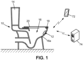
- FIG. 1 illustrates toilets 10 equipped with a urine analysis device 12.
- the toilet 10 comprises a water tank 14, a bowl 16, a seat 18 and a cover 20.
- the urine analysis device 12 is arranged on an internal wall 16a of the bowl 16 of the toilet 10
- the urinalysis device 12 is entirely received in the toilet 10.
- the urinalysis device 12 is discreet.
- the urine analysis device 12 is positioned on the internal wall 16a of the toilet 10 by a fixing element 22.
- the fixing element 22 makes it possible to easily remove the urine analysis device 12 from the toilet 10, for example to recharge a battery 68 of the urine analysis device 12.
- the fixing element 22 can remain positioned on the toilet 10, while the urine analysis device 12 can be removed.
- the fixing element 22 here comprises a suction cup 24 and magnets 26.
- the suction cup 24 can adhere to the internal wall 16a of the toilet 10.
- the magnets 26 are intended to cooperate with a fastener, here comprising magnets or magnetic parts, of the urinalysis device 12.
- a hook-type mechanical coupling can cause the fixing element 22 and the urinalysis device 12 to cooperate.
- the positioning of the fixing element 22 can be chosen so that the urine analysis device 12 is on a trajectory of the jet of urine secreted by a user.
- the urine analysis device 12 can be positioned so as to be in the trajectory of the user's urine stream regardless of their gender.
- the fixing element 22 may comprise an adhesive, in particular a sticker. Still as a variant, the fixing element 22 may comprise a hook configured to engage with a rim of the bowl 16.
- the urine analysis device 12 is positioned on the internal wall 16a of the toilet 10 without using a dedicated fixing element.
- the attachment of the device alone can allow such positioning.
- the attachment of the device may be a hook configured to engage with a rim of the toilet 10.
- the element fixing 22 when used, the latter can remain in place in the toilet 10 when the urinalysis device 12 is removed from the toilet 10.
- the fixing element 22 is housed in a housing provided on the urine analysis device 12.
- the housing can be provided at the level of the battery charging connectors 68 of the urine analysis device urine 12.
- the charging connectors can be protected from toilet water 10.
- the fixing element 22 may also include mechanical aids.
- Mechanical aids can for example be indentations. Mechanical aids can facilitate the positioning of the urine analysis device 12 when it is inserted into the toilet 10. The correct position of the urine analysis device 12 in the toilet 10 ensures the proper functioning of the analysis device urine 12.
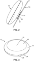
- the urine analysis device 12 here has the shape of a circular pebble.
- the urine analysis device 12 thus has a shape allowing urine to flow onto the exterior surfaces of the urine analysis device 12.
- the contact time between the urine analysis device 12 and the urine secreted by a user in the toilet 10 is improved.
- the user does not need to “aim” to ensure that a jet of urine comes into contact with the urine analysis device 12.
- the circular pebble shape also gives a discreet and aesthetic appearance to the device urine analysis 12.
- the urine analysis device 12 comprises a housing 28 and a heat-conducting plate 30, mounted on the housing or integrated into the housing.
- the conductive plate 30 comprises a free face 40 intended to be oriented towards the inside of the bowl 16 of the toilet 10.
- the jet of urine can come into contact with the urine analysis device 12 and flow onto the free face 40 conductive plate 30.
- the temperature of the urine jet is transmitted to the conductive plate 30.
- the conductive plate 30 acts as a spatial low-pass filter making it possible to homogenize the temperature of the urine over the entire surface of the conductive plate 30 .
- the conductive plate 30 also includes a rear face 42, opposite the free face 40 and oriented towards the housing 28 or towards the interior of the housing 28.
- the rear face 42 makes it possible to transmit the temperature of the urine measured by the free face 40 from the conductive plate 30 to electronic components contained inside the housing 28.
- the conductive plate 30 extends over the majority of a front face of the housing 28.
- the conductive plate 30 occupies in particular a surface greater than 80% of the front face of the housing 28.
- the front face of the housing 28 designates the face oriented towards the interior of the bowl 16 of the toilet 10 when the urine analysis device 12 is received in the toilets 10. The surface of the urine analysis device 12 available to come into contact with the urine is thus optimized.
- the conductive plate 30 may have a surface area greater than 3,500 mm 2 , or even greater than 3,800 mm 2 . Such a surface allows a good compromise between the surface available for measuring the temperature of the urine and the size of the urine analysis device 12.
- the conductive plate 30 is of substantially circular shape.
- the diameter D1 of the conductive plate 30 is between 60 and 80 mm, for example 70 mm or approximately 70 mm.
- the diameter D2 of the housing 28, in the shape of a circular roller, is here between 75 and 110 mm.
- the conductive plate 30 has a thickness of, for example, between 0.1 mm and 0.5 mm. In one embodiment, the conductive plate 30 has a thickness of approximately 0.3 mm. The thickness of the conductive plate 30 corresponds to the distance separating the free face 40 and the rear face 42 of the conductive plate 30. Such thickness ensures a low heat capacity of the conductive plate 30 for good thermal transfer of urine towards the device, while ensuring that the conductive plate 30 has sufficient rigidity for its integration into the urine analysis device 12.
- the conductive plate 30 can also be curved towards the outside of the housing 28. Such a conductive plate 30 is compatible with the circular roller shape of the urine analysis device 12.
- the conductive plate 30 is made of heat-conducting metal.
- the metal forming the conductive plate 30 is chosen to have good heat conduction properties.
- the conductive plate 30 is made of aluminum. Indeed, aluminum has good resistance to humidity and maintains good aesthetics when the urine analysis device 12 is exposed to water or urine.
- the conductive plate 30 could be made of a copper alloy or a stainless steel.
- the conductive plate 30 could be made of a heat-conducting plastic. Such plastic may include a polymer containing current-conducting elements such as graphite or containing ceramics such as aluminum nitride.
- the conductive plate 30 can be fixed on the housing 28 by gluing, screwing or any other means accessible to those skilled in the art.
- a seal may be provided between the conductive plate 30 and the housing 28. The seal makes it possible to isolate the interior of the housing 28 from the water in the toilet 10.
- the housing 28 makes it possible to house the electronic components of the urine analysis device 12 and to protect them from the jet of urine by housing them in a sealed volume (by waterproof, we mean essentially waterproof, that is to say waterproof against unwanted introductions of urine into the device).
- the sealed volume can also be closed by the conductive plate 30.
- the housing 28 and the conductive plate 30 thus define the sealed volume, inside which the electronic components of the analysis device 12 can be housed.
- the housing 28 comprises a front shell 32 and a rear shell 34.
- the front shell 32 and the rear shell 34 can for example be connected by screwing.
- a seal may be provided between the front shell 32 and the rear shell 34.
- the electronic components contained in the housing 28 can be protected from water from the toilet 10.
- the housing 28 is made of a thermal insulating material. Thermal transfers from the housing 28 to the heat conductive plate 30 can be reduced. The influence of the housing 28 on the temperature of the conductive plate 30 is reduced.
- the housing 28 is made of plastic, in particular a non-conductive plastic. The housing 28 then has good thermal insulation, while being relatively inexpensive and easily manufactured, in particular by injection molding.
- the housing 28 defines an opening 36 intended to receive the conductive plate 30.
- the opening 36 makes it possible to reduce the contact surface between the housing 28 and the conductive plate 30, further limiting the thermal transfers between the housing 28 and the conductive plate 30. The influence of the temperature of the housing 28 on the temperature of the conductive plate 30 is reduced.
- the housing 28 can define a reinforcing structure.
- the reinforcing structure can for example take the form of ribs extending inside the housing 28.
- the reinforcing structure can support the conductive plate 30, so as to increase its rigidity.
- the urine analysis device 12 comprises a plurality of temperature sensors 44 received inside the housing 28.
- Each temperature sensor 44 makes it possible to locally obtain temperature information from the conductive plate 30.
- the information of temperature can be a temperature value, that is to say a discrete measurement, or a measurement of the evolution of the temperature over time, that is to say a continuous or quasi-continuous measurement.
- temperature information can be obtained by recovering the voltage across the temperature sensor. After processing, the temperature information can make it possible to obtain urine temperature data. The treatment will be described later.
- each temperature sensor 44 makes it possible to measure the temperature and/or the evolution of the temperature (by taking a plurality of temperature measurements) of at least one portion of the conductive plate 30, which is a portion located in the vicinity of the temperature sensor 44.
- Each temperature sensor 44 has a time constant of less than 1 second, preferably less than 0.2 seconds. The time constant characterizes the response of the temperature sensor 44 to a change in temperature. Each temperature sensor 44 can thus record information about the temperature of the conductive plate 30 caused by a short jet of urine. Each temperature sensor 44 can also record temperature information when the contact of the urine with the conductive plate 30 is of short duration.
- each temperature sensor 44 is a thermistor. Indeed, thermistors are not very sensitive to ambient disturbances, are not very complex to operate and can cover a wide range of temperatures. They are also easily accessible. Alternatively, each temperature sensor 44 could be a solid-state temperature sensor. Such temperature sensors have good robustness and good precision while being relatively inexpensive. Alternatively, each temperature sensor 44 may be a thermopile infrared sensor.
- Certain sensors (such as thermistors, semiconductor temperature sensors and infrared thermopile sensors) also make it possible to continuously measure the temperature, and, therefore, to measure the evolution over time (for example during 'urination) of the temperature.
- the device 12 includes a plurality of temperature sensors 44 (seven temperature sensors illustrated).
- the temperature sensors 44 are positioned so as to allow temperature information to be measured at several locations on the conductive plate 30.
- the plurality of temperature sensors 44 makes it possible to increase the probability that one of the temperature sensors is located at the vicinity of the point of impact of the jet of urine on the conductive plate 30.
- the temperature information measured by the temperature sensor 44 close to the point of impact can then be used to determine the temperature data of the urine with more precision.
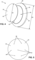
- FIG 5 illustrates an example of arrangement of the plurality of temperature sensors 44 on the rear face 42 of the conductive plate 30.
- the sensors 44 are thus protected by the housing 28, that is to say they are in the volume waterproof defined by the housing 28 and the conductive plate 30.
- seven temperature sensors 44 are arranged on the rear face 42 of the conductive plate 30.
- the number of temperature sensors 44 can be chosen according to the dimensions and the thickness of the conductive plate 30.
- the number of temperature sensors 44 is adapted to the conductivity of the conductive plate 30 and its dimensions.
- the plurality of temperature sensors comprises between 2 and 20 temperature sensors, or even between 3 and 10 or even 5 and 10.
- the distribution of the temperature sensors on the conductive plate 30 can be regular (for example: every 60 ° in a circle around the center of the plate, with or without a temperature sensor at the center; for example every 90° with or without a temperature sensor at the center) or essentially regular.
- a majority of the plurality of temperature sensors 44 is located on a lower portion of the conductive plate 30 (on the Figure 5 , at least four of the seven temperature sensors are on the lower portion).
- the lower portion of the conductive plate 30 corresponds to the portion of the conductive plate 30 oriented towards the bottom of the bowl 16 of the toilet 10 when the urine analysis device 12 is received in the toilet 10. Therefore, the temperature sensors 44 can exploit the runoff of urine on the free face 32 of the conductive plate 30.
- the runoff of urine increases the contact time of the conductive plate 30 with the urine, thus improving the transfer of heat from the urine to the conductive plate 30.
- the temperature information measured by each temperature sensor 44 can tend towards the temperature of the urine.
- FIG. 6 illustrates in more detail an example of temperature sensor 44.
- the temperature sensor 44 comprises a flat face 46.
- the flat face 46 can be in contact with the rear face 42 of the conductive plate 30 to improve the transfer heat from the conductive plate 30 to the temperature sensor 44.
- Each temperature sensor 44 is glued to the rear face 34 of the conductive plate 30 using a heat-conducting glue.
- the conductive glue ensures good heat transfer from the conductive plate 30 to the temperature sensor 44.
- the conductive glue can in particular be an glue polymerized by ultraviolet (UV).
- UV ultraviolet
- the conductive glue in particular allows good mechanical retention of each temperature sensor 44 on the conductive plate 30.
- the conductive glue can also be a thermal paste, in particular a hardening thermal paste. The thermal paste makes it possible to further improve heat conduction from the conductive plate 30 to the temperature sensor(s) 44.
- each temperature sensor 44 is glued using the same volume of conductive glue.
- the same volume of glue ensures that the thermal transfer is substantially identical from one temperature sensor 44 to another.
- the device 12 further comprises one or more processing units 48.
- Each temperature sensor 44 is integrated into a processing unit 48.
- the processing unit 48 comprises an electronic circuit 50 and a calculation unit 52.
- the electronic circuit 50 typically comprises a voltage divider bridge 51, a filtering and amplification stage 54 and an analog-digital converter 56.
- the voltage divider bridge 51 makes it possible to linearize a signal, typically a voltage signal, generated by the temperature sensor 44.
- the voltage divider bridge 51 makes it possible to overcome the non-linear relationship between the signal generated by the sensor 44 and the temperature. It appears possible to calibrate the temperature sensor(s) 44 from two measurement points.
- the filtering and amplification stage 54 is connected to an output of the voltage divider bridge 51.
- the filtering can in particular be a low-pass filter applied to the output signal of the voltage divider bridge. voltage 51. Filtering helps reduce noise and other high-frequency artifacts that may be found in the signal.
- Amplification consists of applying a gain to the signal, making it possible to increase the sensitivity of the circuit to the change in temperature of the conductive plate 30.
- each temperature sensor 44 can measure a temperature range from 14°C to 41 °C, with a resolution of 1 thousandth of a degree.
- the analog-digital converter 56 is connected to an output of the filtering and amplification stage 54.
- the digital signal obtained can be processed by the calculation unit 58.
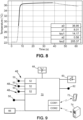
- FIG 8 illustrates an example of temperature evolution of the conductive plate 30 measured by the temperature sensor 44 when the user has urinated.
- the evolution of the temperature illustrated corresponds to the output signal of the electronic circuit 50.
- the calculation unit 52 is configured to determine the temperature data of the urine from the temperature information obtained by the temperature sensor 44 .
- the calculation unit 52 performs a regression of two exponentials on the temperature evolution to analytically determine the temperature data.
- the temporal evolution of the temperature can be described with a combination of two simultaneous processes.
- the first process is a rapid increase in temperature linked to the supply of heat to the conductive plate 30 by urine.
- the second process is a slower rise in temperature linked to the increase in the air temperature inside the housing 28. Therefore, the regression of two exponentials makes it possible to take into account the two processes.
- T has 0 ⁇ has 1 ⁇ e ⁇ t ⁇ 1 ⁇ has 2 ⁇ e ⁇ t ⁇ 2
- the first exponential (index 1) models the thermal transfers between the urine and the conductive plate 30, and the second exponential (index 2) models the thermal transfers between the air inside the housing 28 and the conductive plate 30.
- the limit value of the regression curve is 0 .
- the limit value corresponds to the urine temperature data measured by the temperature sensor 44.
- the temperature data is thus determined analytically by regression of the evolution of the temperature measured by each temperature sensor 44, using the value ao limit determined by regression. This makes it possible to improve the quality of the measurement, notably allowing better precision and optimization of information.
- no regression can be used and the maximum temperature measured using the temperature sensors is taken as the temperature data.
- the temperature data is thus determined empirically.
- each calculation unit 52 determines urine temperature data.
- a final temperature can be chosen from the determined temperature data.
- the final temperature could correspond to an average of the temperatures determined by each calculation unit 52 (either analytically or empirically, as described previously).
- the final temperature is chosen as the maximum temperature among the determined temperature data.
- the maximum temperature can correspond to that determined by the temperature sensor 44 closest to the point of impact of the jet of urine on the conductive plate 30. Then, the final temperature data chosen is the most faithful to the temperature of the urine jet. 'urine.
- the urine analysis device may include various electronic components.
- the urinalysis device 12 may include an additional temperature sensor 58.
- the additional temperature sensor 58 may be placed in the housing 28 to estimate the temperature of the air in the housing 28.
- the additional temperature sensor 58 can thus account for the thermal transfers with the air in the housing 28.
- the urine analysis device 12 may comprise an indicator light 60.
- the indicator light 60 may for example comprise one or more light-emitting diodes (LED).
- the indicator light 60 can be visible from outside the housing 28.
- the indicator light 60 can make it possible to inform the user of a state of the urinalysis device 12.
- the indicator light 60 can indicate a state of charge of the battery 64, that an analysis is in progress or that an analysis has been carried out.
- the indicator light 60 can for example light up when a temperature above a predetermined threshold is detected by the temperature sensor(s) 44.
- the predetermined threshold can be 35°C.
- the predetermined threshold corresponds to a situation where a jet of urine is received on the conductive plate 30.
- the urinalysis device 12 may include a button 62.
- the button 62 is placed inside the housing 28.
- the button 62 can be accessed by the user by unscrewing the front shell 32 from the rear shell 34 of the housing 28.
- the button 62 can for example make it possible to reset the urine analysis device 12 and/or to initiate a wireless association of the device 12 with a nearby device, for example a smartphone.
- the urine analysis device 12 may also include a test set 66.
- the test set 66 may for example make it possible to detect the concentration of one or more compounds in the urine.
- the housing 28 has a collection orifice for collecting a urine sample.
- the test assembly 68 may route the collected urine sample from the collection port for analysis.
- the test assembly 66 can perform a colorimetric analysis on the urine sample.
- the urine sample can be injected onto a test strip.
- the test strip is then analyzed by an optical system.
- the urine analysis device 12 is powered by the battery 68, in particular of the lithium ion type.
- the battery 68 is arranged in the housing 28 to power the electronic components of the urine analysis device 12.
- the battery 68 has for example a capacity of 1080 mAH. Such a capacity is a good compromise between the size of the battery 68 in the case 28 and its autonomy.
- Battery 68 includes charging connectors.
- the charging connectors can be accessible from outside the housing 28 to allow the battery to be recharged.
- the urine analysis device 12 can be placed on a base to connect the charging connectors to a power source.
- the urine analysis device 12 includes an electronic control unit 70.
- the electronic control unit 70 is received in the housing 28.
- the electronic control unit 70 is connected to the electronic circuit 50 of each processing unit 48. In addition, the control unit 70 integrates the calculation unit 52 of each processing unit 48. Thus, the control unit 70 acquires the temperature information measured by each temperature sensor 44. The control unit 70 processes each temperature information to determine the urine temperature data, for example by implementing the different treatments (regression, selection of the maximum temperature value, etc.). When the device 12 includes a plurality of temperature sensors 44, the control unit 70 can determine the final temperature data of the urine. The control unit 70 thus makes it possible to generate urine temperature data from the temperature measurements carried out by the temperature sensors 44.
- the control unit 70 is also connected to the other electronic components of the urine analysis device 12.
- the control unit 70 can cooperate with the other electronic components.
- the electronic control unit 70 comprises at least one wireless communication module, configured to remotely transmit at least the temperature data.
- the electronic control unit 70 may include a first short-range wireless communication module COM1.
- the first communication module COM1 uses a local network, for example of the Bluetooth, Low-Energy Bluetooth (BLE) or Wi-Fi type.
- THE first communication module COM1 communicates with a nearby device 72 of the toilet 10.
- the nearby device 72 can for example be a smartphone, a connected watch or any other device associated with the user.
- the nearby device 72 may be a remote device mounted near the toilet 10.
- Such a remote device may for example include a button and a display.
- the first communication module COM1 may receive an analysis command from the nearby device 72.
- the analysis command informs the urinalysis device 12 that the user wishes to perform an analysis.
- the analysis is in particular a measurement of urine temperature, but could also be any other type of analysis that can be implemented by the urine analysis device 12.
- the first communication module COM1 may also receive an identification of the user from the nearby device 72.
- the identification may allow the urinalysis device 12 to distinguish among different users using the toilet 10. The analysis is then specific to the user.
- the first communication module COM1 can also send an analysis result to the nearby device 72.
- the analysis result includes in particular the urine temperature data, but could also be any other result that can be determined by the device urine analysis 12.
- the user can access the result immediately after an analysis.
- the electronic control unit 70 may include a second wireless communication module COM2.
- the second communication module can be provided in addition to or in substitution for the first communication module COM1.
- the second communication module COM2 uses the cellular network, for example GSM, 3G, 4G(-LTE), LTE-M, 5G or any cellular network dedicated to connected objects.
- the second communication module COM2 gives the urine analysis device 12 a communication interface to a remote server 74.
- the second communication module COM2 can send the analysis result to the remote server 74.
- the result can be sent directly, without passing through a proximity device 72 as described previously.
- the result can then be made accessible to the user from any device suitable for connecting to the server 74, for example the user's smartphone or a computer.
- a plurality of results can be stored by the server 74, making it possible to monitor a plurality of analyses.
- the control unit 70 further comprises a memory MEM.
- the MEM memory can store a plurality of analysis results.
- the plurality of results can be sent periodically to the server 74, for example once a week.
- the frequency of use of the second communication module COM2 can be reduced, reducing the power consumption of the control unit 70.
- the control unit 70 is constructed by a system-on-chip.
- a first Bluetooth Low Energy (BLE) chip may support control of the electronic components of the urine analysis device 12.
- the first BLE chip may also support communication with the nearby device 72.
- a second Wifi chip can support data exchange with the remote server 74.
- the second system-on-chip can be turned off when communication with the server 74 is not used. The energy consumption of the control unit 70 is improved, and the consumption of the battery 68 is reduced.
- the control unit 70 can also be divided into different printed circuits. Each printed circuit can control different electronic components of the urine analysis device 12. A main circuit can ensure cooperation between the different printed circuits. Such a construction allows flexibility as to the construction of the electronic control unit 70 and its integration into the housing 28.
- the urine analysis device 12 initializes an analysis.
- the initialization of an analysis may in particular include the activation of the temperature sensor(s) 44.
- the temperature sensor(s) 44 can continually measure the evolution of the temperature of the conductive plate 30, and the initialization
- An analysis includes starting a recording of the measurement.
- the device 12 can initiate an analysis in response to a request from the user via the nearby device 72.
- the user can for example launch a command from the smartphone or press a button on the remote device.
- the device 12 may initiate an analysis in response to detection by the urinalysis device 12 of the nearby device 72, worn by the user.
- detection may include detection that the proximity device 72 is at a distance from the urine analysis device 12 that is less than a threshold (e.g. 2m), or less than a threshold for at least a duration predetermined.
- the analysis is then launched automatically, without action on the part of the user.
- the device 12 can initiate an analysis in response to detection of a stream of urine.
- detection may include detection of the temperature sensor(s) 44 that the measured temperature exceeds a predetermined threshold, for example 35°C.
- the analysis can then be launched without communication with the nearby device 72.
- the device 12 measures the temperature to generate temperature data.
- Each temperature sensor 44 locally measures temperature information from the conductive plate 30 while the user is urinating. For example, information is a change in temperature over time. Then, the temperature can be measured until the temperature of the conductive plate 30 falls below the threshold. The temperature change can also be measured for a specific duration, for example between 2 and 4 minutes.
- the temperature information measured by each sensor 44 can be linearized to facilitate the calibration of the temperature sensor(s).
- the temperature information can also be amplified to improve measurement sensitivity and filtered to reduce measurement noise. Temperature measurements can further be converted into a digital signal for processing.
- the device 12 uses the temperature measurements of the plate to determine urine temperature data.
- each temperature information can be used to determine urine temperature data.
- the temperature of urine can, for example, be determined by applying a two-exponential regression on the temperature evolution. The limit value of the regression curve is then chosen as the urine temperature data.
- the estimated urine temperature data for each temperature sensor 44 can be compared. More particularly, the maximum temperature can be identified. The maximum temperature can be chosen as the final urine temperature data.
- the device 12 transmits the determined temperature data to the nearby device 72.
- the nearby device 72 can display the temperature data to the user.
- the nearby device 72 may also display a curve including illustrating the temperature data and previously measured temperature data. The user can thus visualize temperature variations over time.
- the urine temperature data can be sent to the remote server 74, typically without passing through the nearby device.
- the remote server 74 can store the measurements taken to allow the user to access them.
- the urine analysis device 12 can allow a user to identify a fertility window.
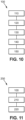
- a method 200 for monitoring the fertile period with reference to the Figure 11 .
- the method 200 comprises a first step of implementing the method 100 described above.
- the temperature data is compared to temperature data obtained previously.
- a temperature measurement is taken every day, and the previous temperature data correspond to the measurements taken on the days preceding that of obtaining the new temperature data.
- a third step 220 the variations between the different temperature data are identified.
- the variations make it possible to identify the stage of the user's menstrual cycle. For example, a drop in temperature may indicate the beginning of a fertile period and an increase in temperature may indicate that ovulation has occurred.
- the urine analysis device 12 can make it possible to identify a feverish episode.
- variations between different temperature data can detect an abnormal increase in basal temperature.
- the urine analysis device 12 described above is not limited only to the embodiments described above, but is, on the contrary, capable of numerous variants accessible to those skilled in the art.
- the urine analysis device has been described in relation to a toilet 10, called a classic toilet, comprising a seat on which the user can sit. However, the urine analysis device can be installed in a urinal.
- the conductive plate 30 could in particular be textured so as to channel the urine towards the temperature sensor(s) 44. This solution aims to improve the precision of the temperature change measured by the temperature sensor(s) 44.
- a plurality of ribs 76 extend from a periphery of the conductive plate 30 towards a central part of the conductive plate 30.
- the temperature sensor(s) 44 could then be provided at the central part of the conductive plate 30.
- the lower part of the conductive plate 30 has a projection 78.
- the projection 78 makes it possible to retain the urine flowing onto the free face 40 of the conductive plate 30.
- the contact time between the urine and the conductive plate 30 is increased .
- the housing 28 forms a recess 80 in which the conductive plate 30 is received.
- the recess 80 can form a channel extending from an upper part of the housing 28 towards a lower part of the housing 28.
- the conductive plate 30 can extend at the level of the lower part, so that the urine circulating in the channel flows over the conductive plate 30.
- the housing 28 and the conductive plate 30 could be made in one piece.
- the entire exterior surface of the urine analysis device 12 is then made of heat-conducting material. The heat transfer between the urine and the analysis device 12 can be increased.
- the manufacturing process may involve obtaining a plastic of the housing which is not conductive of heat and a plastic of the conductive plate which is conductive of heat.
- the conductive element load can be adjusted during the manufacturing of the part.
- a part of the mold corresponding to the housing can receive a simple polymer and a part of the mold corresponding to the conductive plate can receive a polymer (for example the same as that for the housing) loaded with conductive elements (see below).
- a process makes it possible to generate a single piece which comprises, thanks to the properties of its materials, regions which are more thermally conductive than others.
Landscapes
- Health & Medical Sciences (AREA)
- Life Sciences & Earth Sciences (AREA)
- Medical Informatics (AREA)
- Engineering & Computer Science (AREA)
- Biomedical Technology (AREA)
- Heart & Thoracic Surgery (AREA)
- Pathology (AREA)
- Molecular Biology (AREA)
- Surgery (AREA)
- Animal Behavior & Ethology (AREA)
- General Health & Medical Sciences (AREA)
- Public Health (AREA)
- Veterinary Medicine (AREA)
- Hematology (AREA)
- Investigating Or Analysing Biological Materials (AREA)
Claims (15)
- Urinanalysevorrichtung (12), die so konfiguriert ist, dass sie vollständig innerhalb einer Toilette (10) positioniert werden kann, wobei die Vorrichtung umfasst:- ein Gehäuse (28),- eine wärmeleitende Platte (30), die an dem Gehäuse (28) angebracht ist und eine freie Seite (40) aufweist, die dazu bestimmt ist, einen Urinstrahl direkt von einem Benutzer aufzunehmen, der in die Toilette (10) uriniert,wobei die Vorrichtung dadurch gekennzeichnet ist, dass sie außerdem umfasst:- eine Vielzahl von Temperatursensoren (44), wobei jeder Temperatursensor (44) so konfiguriert ist, dass er lokal eine Temperaturinformation der leitfähigen Platte (30) misst.
- Vorrichtung nach Anspruch 1, wobei die leitfähige Platte (30) eine Fläche von mehr als 3.500 mm2, z. B. mehr als 3.800 mm2, aufweist.
- Vorrichtung nach Anspruch 1 oder 2, wobei die leitfähige Platte (30) aus einem wärmeleitenden Metall besteht, z. B. besteht die leitfähige Platte (30) aus Aluminium.
- Vorrichtung nach einem der Ansprüche 1 bis 3, wobei der mindestens eine Temperatursensor (44) in einem Volumen positioniert ist, das durch das Gehäuse (28) und die wärmeleitende Platte (30) definiert ist.
- Vorrichtung nach einem der Ansprüche 1 bis 4, bei der sich eine Mehrheit der mehreren Temperatursensoren (44) auf einem unteren Abschnitt der leitenden Platte (30) befindet, wobei der untere Abschnitt der leitenden Platte (30) dazu bestimmt ist, zum Boden der Toilette (10) zu weisen.
- Vorrichtung nach einem der Ansprüche 1 bis 5, die so konfiguriert ist, dass sie aus den von der Vielzahl von Temperatursensoren (44) ermittelten Temperaturen die Höchsttemperatur als Endtemperaturangabe für den Urin auswählt.
- Vorrichtung nach einem der Ansprüche 1 bis 6, mit mindestens einer Verarbeitungseinheit (48), die so konfiguriert ist, dass sie aus der vom Temperatursensor (44) gemessenen Temperaturinformation eine Temperaturangabe des Urins ermittelt.
- Vorrichtung nach Anspruch 7, wobei das Bestimmen der Temperaturdaten des Urins das Durchführen einer zweifach exponentiellen Regression auf die Temperaturinformation und das Auswählen des Grenzwerts der Regression als die Temperaturdaten des Urins umfasst.
- Vorrichtung nach einem der Ansprüche 1 bis 8, wobei das Gehäuse (28) eine Öffnung (36) definiert, die die wärmeleitende Platte (30) aufnimmt.
- Vorrichtung nach einem der Ansprüche 1 bis 9, wobei die Vorrichtung (12) eine kreisförmige Rollenform aufweist, und/oder wobei die leitende Platte (30) aus dem Gehäuse (28) heraus gewölbt ist.
- Vorrichtung nach einem der Ansprüche 1 bis 10, die ein Mittel zur drahtlosen Kommunikation (50) mit einem dem Benutzer zugeordneten Kommunikationsgerät (60) und/oder einem entfernten Server (64) umfasst, um mindestens ein Temperaturdatum zu übertragen.
- Verfahren zur Messung der Temperatur von Urin, das von der Vorrichtung nach einem der vorhergehenden Ansprüche durchgeführt wird, umfassend:- Messen mindestens einer Temperaturinformation mit Hilfe der Vielzahl von Temperatursensoren (44), wenn ein Urinstrahl auf die freie Seite (40) der leitfähigen Platte (30) trifft;- Bestimmen einer Temperaturangabe des Urins aus der Temperaturinformation.
- Verfahren nach Anspruch 12, wobei das Bestimmen der Temperaturdaten des Urins das Durchführen einer Zwei-Exponential-Regression auf die Temperaturinformation und das Auswählen des Grenzwerts der Regression als die Temperaturdaten des Urins umfasst.
- Verfahren nach einem der Ansprüche 12 oder 13, wobei jeder Temperatursensor die Bestimmung von Temperaturdaten des Urins ermöglicht und das Verfahren die Auswahl der Höchsttemperatur aus den bestimmten Temperaturen als endgültige Temperaturdaten des Urins umfasst.
- Verfahren zur Überwachung einer fruchtbaren Periode, umfassend:- Durchführen des Temperaturmessverfahrens nach einem der Ansprüche 12 bis 14;- Vergleichen der Temperaturdaten des Urins mit Temperaturdaten früherer Urine;- Erfassen von Abweichungen zwischen den Temperaturdaten, um eine Periode des Menstruationszyklus zu bestimmen.
Applications Claiming Priority (2)
| Application Number | Priority Date | Filing Date | Title |
|---|---|---|---|
| FR2101762A FR3119977B1 (fr) | 2021-02-23 | 2021-02-23 | Dispositif d’analyse d’urine pour mesurer la température de l’urine |
| PCT/FR2022/050293 WO2022180328A1 (fr) | 2021-02-23 | 2022-02-18 | Dispositif d'analyse d'urine pour mesurer la température de l'urine |
Publications (2)
| Publication Number | Publication Date |
|---|---|
| EP4274486A1 EP4274486A1 (de) | 2023-11-15 |
| EP4274486B1 true EP4274486B1 (de) | 2024-05-22 |
Family
ID=75690458
Family Applications (1)
| Application Number | Title | Priority Date | Filing Date |
|---|---|---|---|
| EP22710655.6A Active EP4274486B1 (de) | 2021-02-23 | 2022-02-18 | Urinanalysegerät zur messung der temperatur des urins |
Country Status (3)
| Country | Link |
|---|---|
| EP (1) | EP4274486B1 (de) |
| FR (1) | FR3119977B1 (de) |
| WO (1) | WO2022180328A1 (de) |
Families Citing this family (1)
| Publication number | Priority date | Publication date | Assignee | Title |
|---|---|---|---|---|
| FR3162619A1 (fr) * | 2024-05-30 | 2025-12-05 | Withings | Bras de fixation pour dispositif d'analyse d'urine |
Family Cites Families (6)
| Publication number | Priority date | Publication date | Assignee | Title |
|---|---|---|---|---|
| JPS63176536A (ja) * | 1987-01-14 | 1988-07-20 | オムロン株式会社 | 尿体温計 |
| JPS63189537A (ja) * | 1987-01-30 | 1988-08-05 | 東陶機器株式会社 | 体温測定便器 |
| US5062304A (en) * | 1989-05-12 | 1991-11-05 | Endotherapeutics | Urine collection monitor with temperature sensing |
| AU2003272064A1 (en) * | 2002-10-18 | 2004-05-04 | S.A.E. Afikim Computerized Dairy Management System | System for monitoring the health of an individual and method for use thereof |
| WO2005092177A1 (en) * | 2004-03-22 | 2005-10-06 | Bodymedia, Inc. | Non-invasive temperature monitoring device |
| WO2020221943A1 (es) * | 2019-04-29 | 2020-11-05 | S-There Technologies, S.L. | Dispositivo de análisis de orina para la monitorizacion de la salud y procedimiento relacionado |
-
2021
- 2021-02-23 FR FR2101762A patent/FR3119977B1/fr active Active
-
2022
- 2022-02-18 WO PCT/FR2022/050293 patent/WO2022180328A1/fr not_active Ceased
- 2022-02-18 EP EP22710655.6A patent/EP4274486B1/de active Active
Also Published As
| Publication number | Publication date |
|---|---|
| WO2022180328A1 (fr) | 2022-09-01 |
| EP4274486A1 (de) | 2023-11-15 |
| FR3119977A1 (fr) | 2022-08-26 |
| FR3119977B1 (fr) | 2025-07-11 |
Similar Documents
| Publication | Publication Date | Title |
|---|---|---|
| EP4087495B1 (de) | Vorrichtung und verfahren zur analyse von urin | |
| EP4087496B1 (de) | Urinanalyseverfahren und -vorrichtung | |
| US6236214B1 (en) | Method and apparatus for determining the remaining operation time of a mobile communication unit | |
| EP4274486B1 (de) | Urinanalysegerät zur messung der temperatur des urins | |
| WO2019141743A1 (fr) | Système de surveillance corporelle avec adhésif | |
| CN102727218A (zh) | 柔性眼插入物和葡萄糖测量系统 | |
| US20200205717A1 (en) | Method and Apparatus for Collecting and Analyzing Urine Samples | |
| FR3071794B1 (fr) | Balai d'essuie-glace | |
| CA2280598A1 (fr) | Dispositif electronique portable avec circuit de controle de la decharge d'une batterie, et procede associe | |
| FR3105105A1 (fr) | Dispositif de mesure et d’information de la qualité de l’air | |
| EP3876708A1 (de) | Überwachung des wohlbefinden und/oder des komforts von vieh | |
| JPH09297832A (ja) | 生化学測定器 | |
| EP3513846B1 (de) | Analysesystem und dazu passendes gleitbrett | |
| FR2975517A1 (fr) | Enregistrement automatique de la position de stationnement d'un vehicule | |
| FR3060505A1 (fr) | Procede de controle de prise en main d’un organe de direction de vehicule | |
| FR2831263A1 (fr) | Procede et dispositif d'acquisition et de collecte de grandeurs physiques mesurables | |
| WO2017118706A1 (fr) | Dispositif d'obtention d'au moins un paramètre physiologique | |
| CH716795B1 (fr) | Dispositif et procédé de détection d'hydratation pour récipient de boisson liquide. | |
| KR100623031B1 (ko) | 통계를 이용한 이동통신 단말기의 배터리 사용 가능시간측정 방법 | |
| EP1325292A1 (de) | Nichtinvasives elektronisches thermometer | |
| FR3166975A1 (fr) | Station de nettoyage pour dispositif d'analyse d'urine | |
| FR3146922A1 (fr) | Dispositif autonome de mesure pour bassin, système comportant un tel dispositif et procédé d’aide à une gestion d’un bassin | |
| FR3117468A1 (fr) | Ensemble de collecte de déchets | |
| WO2024003814A1 (fr) | Procédé d'analyse d'une sueur émise par une peau d'un utilisateur et dispositif d'analyse pour mettre en oeuvre un tel procede | |
| EP4254358A1 (de) | Verfahren zum zählen von personen und zur bestimmung der position in einem raum |
Legal Events
| Date | Code | Title | Description |
|---|---|---|---|
| STAA | Information on the status of an ep patent application or granted ep patent |
Free format text: STATUS: UNKNOWN |
|
| STAA | Information on the status of an ep patent application or granted ep patent |
Free format text: STATUS: THE INTERNATIONAL PUBLICATION HAS BEEN MADE |
|
| PUAI | Public reference made under article 153(3) epc to a published international application that has entered the european phase |
Free format text: ORIGINAL CODE: 0009012 |
|
| STAA | Information on the status of an ep patent application or granted ep patent |
Free format text: STATUS: REQUEST FOR EXAMINATION WAS MADE |
|
| 17P | Request for examination filed |
Effective date: 20230809 |
|
| AK | Designated contracting states |
Kind code of ref document: A1 Designated state(s): AL AT BE BG CH CY CZ DE DK EE ES FI FR GB GR HR HU IE IS IT LI LT LU LV MC MK MT NL NO PL PT RO RS SE SI SK SM TR |
|
| GRAP | Despatch of communication of intention to grant a patent |
Free format text: ORIGINAL CODE: EPIDOSNIGR1 |
|
| STAA | Information on the status of an ep patent application or granted ep patent |
Free format text: STATUS: GRANT OF PATENT IS INTENDED |
|
| DAV | Request for validation of the european patent (deleted) | ||
| DAX | Request for extension of the european patent (deleted) | ||
| INTG | Intention to grant announced |
Effective date: 20240314 |
|
| GRAS | Grant fee paid |
Free format text: ORIGINAL CODE: EPIDOSNIGR3 |
|
| GRAA | (expected) grant |
Free format text: ORIGINAL CODE: 0009210 |
|
| STAA | Information on the status of an ep patent application or granted ep patent |
Free format text: STATUS: THE PATENT HAS BEEN GRANTED |
|
| AK | Designated contracting states |
Kind code of ref document: B1 Designated state(s): AL AT BE BG CH CY CZ DE DK EE ES FI FR GB GR HR HU IE IS IT LI LT LU LV MC MK MT NL NO PL PT RO RS SE SI SK SM TR |
|
| REG | Reference to a national code |
Ref country code: GB Ref legal event code: FG4D Free format text: NOT ENGLISH |
|
| REG | Reference to a national code |
Ref country code: CH Ref legal event code: EP |
|
| REG | Reference to a national code |
Ref country code: DE Ref legal event code: R096 Ref document number: 602022003605 Country of ref document: DE |
|
| REG | Reference to a national code |
Ref country code: IE Ref legal event code: FG4D Free format text: LANGUAGE OF EP DOCUMENT: FRENCH |
|
| REG | Reference to a national code |
Ref country code: LT Ref legal event code: MG9D |
|
| REG | Reference to a national code |
Ref country code: NL Ref legal event code: MP Effective date: 20240522 |
|
| PG25 | Lapsed in a contracting state [announced via postgrant information from national office to epo] |
Ref country code: IS Free format text: LAPSE BECAUSE OF FAILURE TO SUBMIT A TRANSLATION OF THE DESCRIPTION OR TO PAY THE FEE WITHIN THE PRESCRIBED TIME-LIMIT Effective date: 20240922 |
|
| PG25 | Lapsed in a contracting state [announced via postgrant information from national office to epo] |
Ref country code: BG Free format text: LAPSE BECAUSE OF FAILURE TO SUBMIT A TRANSLATION OF THE DESCRIPTION OR TO PAY THE FEE WITHIN THE PRESCRIBED TIME-LIMIT Effective date: 20240522 |
|
| PG25 | Lapsed in a contracting state [announced via postgrant information from national office to epo] |
Ref country code: HR Free format text: LAPSE BECAUSE OF FAILURE TO SUBMIT A TRANSLATION OF THE DESCRIPTION OR TO PAY THE FEE WITHIN THE PRESCRIBED TIME-LIMIT Effective date: 20240522 Ref country code: FI Free format text: LAPSE BECAUSE OF FAILURE TO SUBMIT A TRANSLATION OF THE DESCRIPTION OR TO PAY THE FEE WITHIN THE PRESCRIBED TIME-LIMIT Effective date: 20240522 |
|
| PG25 | Lapsed in a contracting state [announced via postgrant information from national office to epo] |
Ref country code: GR Free format text: LAPSE BECAUSE OF FAILURE TO SUBMIT A TRANSLATION OF THE DESCRIPTION OR TO PAY THE FEE WITHIN THE PRESCRIBED TIME-LIMIT Effective date: 20240823 |
|
| PG25 | Lapsed in a contracting state [announced via postgrant information from national office to epo] |
Ref country code: PT Free format text: LAPSE BECAUSE OF FAILURE TO SUBMIT A TRANSLATION OF THE DESCRIPTION OR TO PAY THE FEE WITHIN THE PRESCRIBED TIME-LIMIT Effective date: 20240923 |
|
| REG | Reference to a national code |
Ref country code: AT Ref legal event code: MK05 Ref document number: 1688122 Country of ref document: AT Kind code of ref document: T Effective date: 20240522 |
|
| PG25 | Lapsed in a contracting state [announced via postgrant information from national office to epo] |
Ref country code: NL Free format text: LAPSE BECAUSE OF FAILURE TO SUBMIT A TRANSLATION OF THE DESCRIPTION OR TO PAY THE FEE WITHIN THE PRESCRIBED TIME-LIMIT Effective date: 20240522 |
|
| PG25 | Lapsed in a contracting state [announced via postgrant information from national office to epo] |
Ref country code: ES Free format text: LAPSE BECAUSE OF FAILURE TO SUBMIT A TRANSLATION OF THE DESCRIPTION OR TO PAY THE FEE WITHIN THE PRESCRIBED TIME-LIMIT Effective date: 20240522 |
|
| PG25 | Lapsed in a contracting state [announced via postgrant information from national office to epo] |
Ref country code: AT Free format text: LAPSE BECAUSE OF FAILURE TO SUBMIT A TRANSLATION OF THE DESCRIPTION OR TO PAY THE FEE WITHIN THE PRESCRIBED TIME-LIMIT Effective date: 20240522 |
|
| PG25 | Lapsed in a contracting state [announced via postgrant information from national office to epo] |
Ref country code: PL Free format text: LAPSE BECAUSE OF FAILURE TO SUBMIT A TRANSLATION OF THE DESCRIPTION OR TO PAY THE FEE WITHIN THE PRESCRIBED TIME-LIMIT Effective date: 20240522 |
|
| PG25 | Lapsed in a contracting state [announced via postgrant information from national office to epo] |
Ref country code: LV Free format text: LAPSE BECAUSE OF FAILURE TO SUBMIT A TRANSLATION OF THE DESCRIPTION OR TO PAY THE FEE WITHIN THE PRESCRIBED TIME-LIMIT Effective date: 20240522 |
|
| PG25 | Lapsed in a contracting state [announced via postgrant information from national office to epo] |
Ref country code: PT Free format text: LAPSE BECAUSE OF FAILURE TO SUBMIT A TRANSLATION OF THE DESCRIPTION OR TO PAY THE FEE WITHIN THE PRESCRIBED TIME-LIMIT Effective date: 20240923 Ref country code: PL Free format text: LAPSE BECAUSE OF FAILURE TO SUBMIT A TRANSLATION OF THE DESCRIPTION OR TO PAY THE FEE WITHIN THE PRESCRIBED TIME-LIMIT Effective date: 20240522 Ref country code: NO Free format text: LAPSE BECAUSE OF FAILURE TO SUBMIT A TRANSLATION OF THE DESCRIPTION OR TO PAY THE FEE WITHIN THE PRESCRIBED TIME-LIMIT Effective date: 20240822 Ref country code: NL Free format text: LAPSE BECAUSE OF FAILURE TO SUBMIT A TRANSLATION OF THE DESCRIPTION OR TO PAY THE FEE WITHIN THE PRESCRIBED TIME-LIMIT Effective date: 20240522 Ref country code: LV Free format text: LAPSE BECAUSE OF FAILURE TO SUBMIT A TRANSLATION OF THE DESCRIPTION OR TO PAY THE FEE WITHIN THE PRESCRIBED TIME-LIMIT Effective date: 20240522 Ref country code: IS Free format text: LAPSE BECAUSE OF FAILURE TO SUBMIT A TRANSLATION OF THE DESCRIPTION OR TO PAY THE FEE WITHIN THE PRESCRIBED TIME-LIMIT Effective date: 20240922 Ref country code: HR Free format text: LAPSE BECAUSE OF FAILURE TO SUBMIT A TRANSLATION OF THE DESCRIPTION OR TO PAY THE FEE WITHIN THE PRESCRIBED TIME-LIMIT Effective date: 20240522 Ref country code: GR Free format text: LAPSE BECAUSE OF FAILURE TO SUBMIT A TRANSLATION OF THE DESCRIPTION OR TO PAY THE FEE WITHIN THE PRESCRIBED TIME-LIMIT Effective date: 20240823 Ref country code: FI Free format text: LAPSE BECAUSE OF FAILURE TO SUBMIT A TRANSLATION OF THE DESCRIPTION OR TO PAY THE FEE WITHIN THE PRESCRIBED TIME-LIMIT Effective date: 20240522 Ref country code: ES Free format text: LAPSE BECAUSE OF FAILURE TO SUBMIT A TRANSLATION OF THE DESCRIPTION OR TO PAY THE FEE WITHIN THE PRESCRIBED TIME-LIMIT Effective date: 20240522 Ref country code: BG Free format text: LAPSE BECAUSE OF FAILURE TO SUBMIT A TRANSLATION OF THE DESCRIPTION OR TO PAY THE FEE WITHIN THE PRESCRIBED TIME-LIMIT Effective date: 20240522 Ref country code: AT Free format text: LAPSE BECAUSE OF FAILURE TO SUBMIT A TRANSLATION OF THE DESCRIPTION OR TO PAY THE FEE WITHIN THE PRESCRIBED TIME-LIMIT Effective date: 20240522 Ref country code: RS Free format text: LAPSE BECAUSE OF FAILURE TO SUBMIT A TRANSLATION OF THE DESCRIPTION OR TO PAY THE FEE WITHIN THE PRESCRIBED TIME-LIMIT Effective date: 20240822 |
|
| PG25 | Lapsed in a contracting state [announced via postgrant information from national office to epo] |
Ref country code: DK Free format text: LAPSE BECAUSE OF FAILURE TO SUBMIT A TRANSLATION OF THE DESCRIPTION OR TO PAY THE FEE WITHIN THE PRESCRIBED TIME-LIMIT Effective date: 20240522 |
|
| PG25 | Lapsed in a contracting state [announced via postgrant information from national office to epo] |
Ref country code: EE Free format text: LAPSE BECAUSE OF FAILURE TO SUBMIT A TRANSLATION OF THE DESCRIPTION OR TO PAY THE FEE WITHIN THE PRESCRIBED TIME-LIMIT Effective date: 20240522 |
|
| PG25 | Lapsed in a contracting state [announced via postgrant information from national office to epo] |
Ref country code: CZ Free format text: LAPSE BECAUSE OF FAILURE TO SUBMIT A TRANSLATION OF THE DESCRIPTION OR TO PAY THE FEE WITHIN THE PRESCRIBED TIME-LIMIT Effective date: 20240522 |
|
| PG25 | Lapsed in a contracting state [announced via postgrant information from national office to epo] |
Ref country code: SK Free format text: LAPSE BECAUSE OF FAILURE TO SUBMIT A TRANSLATION OF THE DESCRIPTION OR TO PAY THE FEE WITHIN THE PRESCRIBED TIME-LIMIT Effective date: 20240522 Ref country code: RO Free format text: LAPSE BECAUSE OF FAILURE TO SUBMIT A TRANSLATION OF THE DESCRIPTION OR TO PAY THE FEE WITHIN THE PRESCRIBED TIME-LIMIT Effective date: 20240522 |
|
| PG25 | Lapsed in a contracting state [announced via postgrant information from national office to epo] |
Ref country code: SK Free format text: LAPSE BECAUSE OF FAILURE TO SUBMIT A TRANSLATION OF THE DESCRIPTION OR TO PAY THE FEE WITHIN THE PRESCRIBED TIME-LIMIT Effective date: 20240522 Ref country code: RO Free format text: LAPSE BECAUSE OF FAILURE TO SUBMIT A TRANSLATION OF THE DESCRIPTION OR TO PAY THE FEE WITHIN THE PRESCRIBED TIME-LIMIT Effective date: 20240522 Ref country code: EE Free format text: LAPSE BECAUSE OF FAILURE TO SUBMIT A TRANSLATION OF THE DESCRIPTION OR TO PAY THE FEE WITHIN THE PRESCRIBED TIME-LIMIT Effective date: 20240522 Ref country code: DK Free format text: LAPSE BECAUSE OF FAILURE TO SUBMIT A TRANSLATION OF THE DESCRIPTION OR TO PAY THE FEE WITHIN THE PRESCRIBED TIME-LIMIT Effective date: 20240522 Ref country code: CZ Free format text: LAPSE BECAUSE OF FAILURE TO SUBMIT A TRANSLATION OF THE DESCRIPTION OR TO PAY THE FEE WITHIN THE PRESCRIBED TIME-LIMIT Effective date: 20240522 |
|
| PG25 | Lapsed in a contracting state [announced via postgrant information from national office to epo] |
Ref country code: IT Free format text: LAPSE BECAUSE OF FAILURE TO SUBMIT A TRANSLATION OF THE DESCRIPTION OR TO PAY THE FEE WITHIN THE PRESCRIBED TIME-LIMIT Effective date: 20240522 |
|
| REG | Reference to a national code |
Ref country code: DE Ref legal event code: R097 Ref document number: 602022003605 Country of ref document: DE |
|
| PLBE | No opposition filed within time limit |
Free format text: ORIGINAL CODE: 0009261 |
|
| STAA | Information on the status of an ep patent application or granted ep patent |
Free format text: STATUS: NO OPPOSITION FILED WITHIN TIME LIMIT |
|
| PG25 | Lapsed in a contracting state [announced via postgrant information from national office to epo] |
Ref country code: SI Free format text: LAPSE BECAUSE OF FAILURE TO SUBMIT A TRANSLATION OF THE DESCRIPTION OR TO PAY THE FEE WITHIN THE PRESCRIBED TIME-LIMIT Effective date: 20240522 |
|
| 26N | No opposition filed |
Effective date: 20250225 |
|
| PG25 | Lapsed in a contracting state [announced via postgrant information from national office to epo] |
Ref country code: SE Free format text: LAPSE BECAUSE OF FAILURE TO SUBMIT A TRANSLATION OF THE DESCRIPTION OR TO PAY THE FEE WITHIN THE PRESCRIBED TIME-LIMIT Effective date: 20240522 |
|
| PG25 | Lapsed in a contracting state [announced via postgrant information from national office to epo] |
Ref country code: MC Free format text: LAPSE BECAUSE OF FAILURE TO SUBMIT A TRANSLATION OF THE DESCRIPTION OR TO PAY THE FEE WITHIN THE PRESCRIBED TIME-LIMIT Effective date: 20240522 |
|
| REG | Reference to a national code |
Ref country code: CH Ref legal event code: PL |
|
| PG25 | Lapsed in a contracting state [announced via postgrant information from national office to epo] |
Ref country code: LU Free format text: LAPSE BECAUSE OF NON-PAYMENT OF DUE FEES Effective date: 20250218 |
|
| PG25 | Lapsed in a contracting state [announced via postgrant information from national office to epo] |
Ref country code: CH Free format text: LAPSE BECAUSE OF NON-PAYMENT OF DUE FEES Effective date: 20250228 |
|
| REG | Reference to a national code |
Ref country code: BE Ref legal event code: MM Effective date: 20250228 |
|
| PG25 | Lapsed in a contracting state [announced via postgrant information from national office to epo] |
Ref country code: BE Free format text: LAPSE BECAUSE OF NON-PAYMENT OF DUE FEES Effective date: 20250228 |
|
| PG25 | Lapsed in a contracting state [announced via postgrant information from national office to epo] |
Ref country code: IE Free format text: LAPSE BECAUSE OF NON-PAYMENT OF DUE FEES Effective date: 20250218 |
|
| PGFP | Annual fee paid to national office [announced via postgrant information from national office to epo] |
Ref country code: GB Payment date: 20260219 Year of fee payment: 5 |
|
| PGFP | Annual fee paid to national office [announced via postgrant information from national office to epo] |
Ref country code: DE Payment date: 20260206 Year of fee payment: 5 |
|
| PGFP | Annual fee paid to national office [announced via postgrant information from national office to epo] |
Ref country code: FR Payment date: 20260227 Year of fee payment: 5 |