EP3513846B1 - Analysesystem und dazu passendes gleitbrett - Google Patents
Analysesystem und dazu passendes gleitbrett Download PDFInfo
- Publication number
- EP3513846B1 EP3513846B1 EP19151725.9A EP19151725A EP3513846B1 EP 3513846 B1 EP3513846 B1 EP 3513846B1 EP 19151725 A EP19151725 A EP 19151725A EP 3513846 B1 EP3513846 B1 EP 3513846B1
- Authority
- EP
- European Patent Office
- Prior art keywords
- sliding board
- board
- processing circuit
- electronic processing
- piezoelectric element
- Prior art date
- Legal status (The legal status is an assumption and is not a legal conclusion. Google has not performed a legal analysis and makes no representation as to the accuracy of the status listed.)
- Active
Links
Images




Classifications
-
- A—HUMAN NECESSITIES
- A63—SPORTS; GAMES; AMUSEMENTS
- A63C—SKATES; SKIS; ROLLER SKATES; DESIGN OR LAYOUT OF COURTS, RINKS OR THE LIKE
- A63C11/00—Accessories for skiing or snowboarding
- A63C11/003—Signalling devices, e.g. acoustical or visual
-
- A—HUMAN NECESSITIES
- A63—SPORTS; GAMES; AMUSEMENTS
- A63C—SKATES; SKIS; ROLLER SKATES; DESIGN OR LAYOUT OF COURTS, RINKS OR THE LIKE
- A63C5/00—Skis or snowboards
- A63C5/03—Mono skis; Snowboards
-
- A—HUMAN NECESSITIES
- A63—SPORTS; GAMES; AMUSEMENTS
- A63C—SKATES; SKIS; ROLLER SKATES; DESIGN OR LAYOUT OF COURTS, RINKS OR THE LIKE
- A63C5/00—Skis or snowboards
- A63C5/06—Skis or snowboards with special devices thereon, e.g. steering devices
-
- B—PERFORMING OPERATIONS; TRANSPORTING
- B63—SHIPS OR OTHER WATERBORNE VESSELS; RELATED EQUIPMENT
- B63B—SHIPS OR OTHER WATERBORNE VESSELS; EQUIPMENT FOR SHIPPING
- B63B32/00—Water sports boards; Accessories therefor
- B63B32/20—Boards specially adapted for use in a prone position, e.g. wild-water sledges
-
- H—ELECTRICITY
- H02—GENERATION; CONVERSION OR DISTRIBUTION OF ELECTRIC POWER
- H02N—ELECTRIC MACHINES NOT OTHERWISE PROVIDED FOR
- H02N2/00—Electric machines in general using piezoelectric effect, electrostriction or magnetostriction
- H02N2/18—Electric machines in general using piezoelectric effect, electrostriction or magnetostriction producing electrical output from mechanical input, e.g. generators
- H02N2/186—Vibration harvesters
-
- A—HUMAN NECESSITIES
- A63—SPORTS; GAMES; AMUSEMENTS
- A63C—SKATES; SKIS; ROLLER SKATES; DESIGN OR LAYOUT OF COURTS, RINKS OR THE LIKE
- A63C2203/00—Special features of skates, skis, roller-skates, snowboards and courts
- A63C2203/12—Electrically powered or heated
-
- A—HUMAN NECESSITIES
- A63—SPORTS; GAMES; AMUSEMENTS
- A63C—SKATES; SKIS; ROLLER SKATES; DESIGN OR LAYOUT OF COURTS, RINKS OR THE LIKE
- A63C2203/00—Special features of skates, skis, roller-skates, snowboards and courts
- A63C2203/18—Measuring a physical parameter, e.g. speed, distance
-
- A—HUMAN NECESSITIES
- A63—SPORTS; GAMES; AMUSEMENTS
- A63C—SKATES; SKIS; ROLLER SKATES; DESIGN OR LAYOUT OF COURTS, RINKS OR THE LIKE
- A63C2203/00—Special features of skates, skis, roller-skates, snowboards and courts
- A63C2203/22—Radio waves emitting or receiving, e.g. remote control, RFID
-
- A—HUMAN NECESSITIES
- A63—SPORTS; GAMES; AMUSEMENTS
- A63C—SKATES; SKIS; ROLLER SKATES; DESIGN OR LAYOUT OF COURTS, RINKS OR THE LIKE
- A63C2203/00—Special features of skates, skis, roller-skates, snowboards and courts
- A63C2203/24—Processing or storing data, e.g. with electronic chip
Definitions
- the invention relates to the field of boards for sliding on snow or water, and in particular alpine, cross-country or touring skis, or even snowboards or wakeboards.
- the invention relates more particularly to a system for analyzing the use of a sliding board, that is to say an electronic circuit making it possible to obtain at least one piece of information linked to the use of the sliding board. .
- the invention also relates to an instrumented sliding board, equipped with this analysis system.
- This type of sensor uses the intrinsic behavior of a piezoelectric element which converts mechanical deformation energy into electrical energy.
- an electrochemical battery presents constraints of size and weight, resistance to cold and storage, which are generally not compatible with a gliding board.
- a snow board can be used at temperatures close to -20°C. In this operating temperature range, conventional electrochemical batteries are inefficient or even unusable.
- batteries discharge quickly in the cold and the batteries must often be replaced or recharged by the user, which is very restrictive.
- a snow board is often used occasionally, for example a few days each winter.
- An electrochemical battery on board a snow board would therefore have long periods of inactivity, at least between spring and autumn, during which the electrochemical battery would be completely discharged.
- a gliding board is a mechanical element subject to significant stresses, such as twists or shocks.
- the document WO 2011/160040 describes a skateboard deck with light-emitting diodes arranged under the deck to display light effects on the ground.
- the diodes are normally powered by a battery but one embodiment proposes using a piezoelectric transducer to power these light-emitting diodes.
- this document also proposes incorporating an electronic circuit on the skateboard in order to take measurements over time.
- This electronic circuit is powered by a battery and can integrate a motion sensor as described previously, that is to say a piezoelectric sensor using a measurement of deformation coming from a piezoelectric element.
- the technical problem that the invention proposes to solve is therefore to find how to obtain information linked to the use of a sliding board, such as the duration of use of the sliding board, the number of requests of the sliding board. gliding board, or even the power exerted by the user on the gliding board, while eliminating the need for an additional power source, and in particular an electrochemical battery.
- the invention is defined by claim 1 and proposes to respond to this technical problem by using at least one piezoelectric element secured to a gliding board and by using this piezoelectric element to power an electronic processing circuit.
- the electronic processing circuit includes elements ensuring the determination of parameters linked to the use of the gliding board, such as the duration of use and/or the number of times the gliding board is requested. Said to less piezoelectric element and the associated electronic processing circuit together form an autonomous electronic circuit.
- the invention is characterized in that said electronic processing circuit is powered by said electrical energy generated by said at least one piezoelectric element.
- the invention thus makes it possible to obtain parameters linked to the use of the gliding board using only the energy produced by said at least one piezoelectric element.
- the invention makes it possible to obtain parameters linked to the use of the gliding board without using an additional power source, that is to say without using an electrochemical, rechargeable or non-rechargeable battery, or any other known energy source, for example solar panels.
- the invention makes it possible to obtain an electronic circuit that is very resistant to climatic conditions and periods of inactivity.
- the estimation of the at least one parameter of use of said gliding board produced by said electronic processing circuit is determined as a function of said electrical energy generated by said at least one piezoelectric element.
- said electronic processing circuit comprises at least one capacitive storage element intended to store at least part of said electrical energy generated by said at least one piezoelectric element.
- This capacitive storage element makes it possible to store the energy produced by the at least one piezoelectric element and which would not be used by the electronic circuit. By restoring this energy over time to power the electronic processing circuit in the phases for which the at least one piezoelectric element does not produce sufficient energy to power the electronic processing circuit, the capacitive storage element performs an integration of all the energies produced by said at least one piezoelectric element.
- said electronic processing circuit is configured to estimate a duration of use of the gliding board and/or to estimate an image of the mechanical energy imposed on the gliding board.
- said electronic processing circuit comprises a management member configured to increment at least one binary count when the voltage across said capacitive storage element reaches a threshold value or a maximum reference value so that said at least a binary count represents the duration of use of the gliding board and/or an image of the mechanical energy imposed on the gliding board.
- This binary count is not a direct measurement of the deformations of the surface of the gliding board, the information obtained by this binary count is for example linked to the deformation time of the gliding board, in this case the binary count is called time count, or linked to the amplitude of the deformations of the gliding board, in this case the binary count is called activation count.
- this binary count can be used to estimate the duration and/or intensity of the requests, the actual duration of use of the gliding board, even the wear of this gliding board or the level of commitment of a skier on one or other of his skis.
- the electronic processing circuit comprises a non-volatile memory connected to said management unit, said management unit being configured to write said at least one binary count in memory.
- said management body is configured to write the time count in the non-volatile memory when a minimum reference value internal to the management body is reached.
- said management body is configured to write the activation count in the non-volatile memory when a maximum reference value internal to the management body is reached. This maximum reference value is set beyond the minimum operating voltage of the electronic processing circuit.
- the activation count makes it possible to obtain information linked to the amplitude of the deformations of the surface on which the at least one piezoelectric element is placed.
- said management unit comprises an internal clock, said management unit being configured to increment a time count at each period of said internal clock as soon as the management unit is powered on. This time count makes it possible to obtain information linked to the deformation time of the surface on which the at least one piezoelectric element is placed. By using the internal clock of the management body, the generation of this time account consumes very little energy.
- This embodiment makes it possible to obtain a time count using very simple and energy-efficient electronic components, namely: an oscillator and a counter.
- the oscillator can be a crystal oscillator and the counter can be made by cascading a series of T flip-flops.
- said electronic processing circuit comprises at least one hysteresis comparator configured to compare the voltage across said capacitive storage element to at least two threshold values.
- the hysteresis comparator is configured to authorize or prohibit powering up of the management unit respectively as a function of a first and a second threshold value.
- the electronic processing circuit comprises a second hysteresis comparator configured to authorize or prohibit switching on of the oscillator and the counter respectively as a function of a third and a fourth threshold value.
- said electronic processing circuit comprises a radio frequency antenna configured to power said non-volatile memory by electromagnetic coupling so that an external reader can obtain, wirelessly, said at least one binary count.
- the power supply by electromagnetic coupling of an autonomous electronic circuit is preferably carried out by radio frequency identification technology, better known by the anagram RFID, for “ radio frequency identification ” in the Anglo-Saxon literature.
- This embodiment thus makes it possible to simply read the memory of the electronic circuit to obtain the binary counts without using a physical connection with the electronic circuit.
- This external drive can correspond to a specific drive, a smartphone, or even a computer.
- said electronic processing circuit comprises a voltage converter arranged at the output of the at least one piezoelectric element, said voltage converter being intended to provide a rectified or direct voltage from the voltage generated by the at least one piezoelectric element.
- the invention relates to a method for analyzing the use of a gliding board implemented by the system as defined according to the first aspect of the invention.
- This method is characterized in that, depending on the voltage across said capacitive storage element, said management member is configured to write said time count and/or said activation count in the non-volatile memory.
- the invention relates to a gliding board comprising a system for analyzing a use of said gliding board according to the first aspect of the invention.
- This third aspect of the invention makes it possible to obtain an instrumented gliding board, that is to say integrating an electronic circuit making it possible to obtain information linked to the use and/or deformation of the gliding board. .
- said electronic circuit is mounted on said at least one piezoelectric element.
- the housing of the electronic circuit has a bending capacity substantially equivalent to that of the at least one piezoelectric element so as to limit the impact of the presence of the housing on the bending capacities of the at least one piezoelectric element.
- the housing can be made from a plastic whose hardness is between 50 and 100 Shore A.
- said gliding board comprises fixing elements mounted between a front end and a rear end of said gliding board, said at least one piezoelectric element being disposed between said fixing elements and said front end of said board gliding.
- This embodiment makes it possible to effectively capture the deformations of the gliding board in a region where the deformations are of significant magnitude.
- the at least one piezoelectric element is placed just in front of the binding because this area is less exposed to shocks, in particular shocks due to crossing skis.
- the upper assembly may also include a protective and decorative layer which is conventionally less rigid than the reinforcing layer.
- the deformations of the reinforcing layer are therefore cushioned by the protective and decorative layer.
- the preferential positioning of the at least one piezoelectric element on the reinforcing layer makes it possible to obtain an undamped and more relevant recording of the deformations of the gliding board.
- said upper assembly comprising a protective and/or decorative layer
- said sliding board comprises an opening in said protective and decorative layer in which said at least one piezoelectric element is positioned.
- This embodiment allows access to the reinforcing layer from the upper face of the gliding board so as to carry out the installation and/or maintenance of the piezoelectric element.
- said sliding board comprises a protective and/or decorative layer, said at least one piezoelectric element being placed in contact with this protective and/or decorative layer.
- said electronic circuit is mounted on said gliding board in a protective box.
- This embodiment makes it possible to protect the electronic circuit from shock and humidity, for example rain and snow.
- said protective box is removably mounted on said gliding board.
- This embodiment makes it possible to facilitate maintenance of the electronic circuit.
- this embodiment makes it possible to move the electronic circuit to analyze the deformations of several gliding boards with the same electronic circuit.
- said gliding board comprises at least one interface element between the upper surface of the gliding board and the fixing elements, said protective housing being fixed to said at least interface element.
- This embodiment makes it possible to effectively fix the protective box with the gliding board by moving the protective box from the binding.
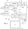
- THE figures 1 And 2 represent two embodiments of an electrical diagram of a system 100 for analyzing the use of a gliding board 25.
- This analysis system 100 is intended to be attached to a sliding board 25 as will be illustrated by the figures 5 to 13 .
- the analysis system 100 comprises, on the one hand, at least one element intended to produce electrical energy following a deformation, such as a piezoelectric element 11a, 11b and, on the other hand, an electronic processing circuit 15.
- the electronic processing circuit 15 comprises a part relating to the storage and management of electrical energy 101, as well as a part 102 relating to the determination of at least one piece of information linked to the use of the gliding board 25 , this part 102 comprising elements ensuring the estimates and calculations linked to the use of the gliding board 25.
- the electronic processing circuit 15 further comprises a part 103 relating to the storage of data. And finally, in order to ensure the communication of this recorded data to a device external to the analysis system 100, the electronic processing circuit 15 comprises a part 104 relating to communication.
- the system 100 comprises at least one piezoelectric element 11a, 11b, here two in number.
- the piezoelectric elements 11a, 11b are not directly connected to each other.
- the piezoelectric elements 11a, 11b can be electrically arranged in parallel.
- the piezoelectric elements 11a, 11b are electrically arranged in series with one another.
- the two piezoelectric elements 11a, 11b are intended to generate an electrical signal during use of the sliding board 25. More precisely, each piezoelectric element 11a, 11b generates an electrical voltage Vpa, Vpb in response to a mechanical deformation that it undergoes. In the presence of several piezoelectric elements 11a, 11b this electrical voltage Vpa, Vpb can vary from one piezoelectric element 11a, 11b to another.
- the electronic processing circuit 15 is only powered by the piezoelectric elements 11a, 11b.
- the analysis system 100 itself forming an electronic circuit composed of piezoelectric elements 11a, 11b as well as the electronic processing circuit 15, is autonomous, that is to say it does not require a source of power supply external to the analysis system 100, such as for example a rechargeable or non-rechargeable battery.
- the piezoelectric elements 11a, 11b provide both the role of source of information for determining the use of the gliding board 25 and the role of source of electrical power, as will be described further away.
- the voltage Vpa, Vpb generated by each piezoelectric element 11a-11b is an alternating, non-continuous voltage, which exhibits great variability in amplitude and frequency.
- the gliding board 25 deforms in flexion when it is used and a surface 12 of the gliding board then undergoes transmitted deformations to the piezoelectric elements 11a-11b which generate a voltage Vpa, Vpb which varies as a function of the deformations undergone by the surface 12.
- a phase P3 called stopping, and a phase P4, called extinction
- the gliding board 25 is stationary and, as a result, it is no longer deformed, also the surface 12 does not undergo deformation and the voltage Vpa, Vpb generated by the piezoelectric elements 11a-11b becomes zero.
- the part relating to the storage and management of electrical energy 101 comprises at least one voltage converter 14, at least one capacitive storage element Cs and at least one voltage comparator 22.
- the intrinsically variable voltage Vpa, Vpb is injected into a voltage converter 14 which provides a rectified or direct voltage from the voltage Vpa, Vpb generated by each piezoelectric element 11a-11b.
- this voltage converter 14 is produced by a diode bridge which provides a rectified voltage.
- the voltage converter 14 is produced by a “buck” type chopper, “boost” type or “buck-boost” type. These choppers have the advantage of providing a direct voltage. It should be noted that each piezoelectric element 11a-11b is connected without an intermediate element to the voltage converter 14. In the case where the piezoelectric elements 11a, 11b are electrically arranged in series or in parallel, a single voltage converter is advantageously provided. 14, which can represent a significant manufacturing saving.
- the voltage Vpa, Vpb generated by the piezoelectric elements 11a-11b is stored in a capacitive storage element Cs, of the super capacitor or capacitor type.
- the capacitive storage element Cs can include several super capacitors or capacitors without changing the invention. In the case where several capacitors are used, they are then electrically arranged in parallel to each other, the sum of the capacities of each of the capacitors making it possible to obtain the equivalent capacity of all the capacitors.
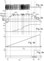
- THE figures 3b And 4b illustrate the voltage Vcs across the capacitive storage element Cs.
- the capacitive storage element Cs In the initial state, that is to say when the sliding board 25 is not used, the capacitive storage element Cs is completely discharged.
- the sliding board 25 In the start-up phases P1 and writing phases P2, the sliding board 25 is used and deforms when flexed, particularly on snow.
- the deformations of the sliding board 25, and therefore of the surface 12 make it possible to charge the capacitive storage element Cs via the piezoelectric elements 11a, 11b.
- the part 101 relating to the storage and management of electrical energy further comprises at least one voltage comparator 22, 22a configured to control the power supply of the part 102 relating to the determination of at least one piece of related information for the use of the sliding board 25.
- the voltage comparator 22, 22a is configured to compare the voltage Vcs at the output of the capacitive storage element Cs to two threshold voltage values S1h, S1b, S0h, S0b, as will be described later in relation to the figure 3b And 4b .
- the voltage comparator 22 is connected on the one hand to the capacitive storage element Cs by a power supply terminal Vcc, to an output switch 21 , to one or more resistors R1, R2, R3 on its positive terminal and to a voltage reference F on its negative terminal.
- a signal inverter 10 is placed at the output of the voltage comparator 22 at the output of the voltage comparator 22, a signal inverter 10 is placed.
- switch 21 is, for example, a PMOS type transistor. Of course, this switch 21 can also be an NMOS type transistor and, in this case, the architecture of the electronic processing circuit 15 must be adapted.
- part 103 relating to data storage comprises at least one non-volatile memory 19, as will be described later. It should be noted that a memory is said to be non-volatile, as long as turning it off does not cause the loss of recorded data.
- part 104 As for part 104 relating to communication, this includes an antenna 20, which will also be described later in the description.
- the electronic processing circuit 15, and in particular its part 102 relating to the determination of at least one piece of information linked to the use of the gliding board 25, comprises a microcontroller 18.
- the microcontroller 18 performs at least one binary count T, M and is configured to compare its supply voltage with respect to at least one reference voltage value REFmax, REFmin. According to this embodiment, the microcontroller 18 produces two binary counts, a temporal binary count T corresponding to a duration of use of the gliding board 25 and a binary count M, called activation count, which aims to represent information linked to the amplitude of the deformations of the sliding board 25.
- the microcontroller 18 estimates both a duration of use and an amplitude of deformations of the sliding board 25.
- a single voltage comparator 22 is provided.
- This voltage comparator 22 performs the hysteresis comparator function allowing the closing or opening of the switch 21 in order to connect, respectively disconnect, the microcontroller 18 to the control element. capacitive storage Cs.
- two thresholds S1h and S1b are defined, respectively called in the remainder of the description power supply threshold S1h and cut-off threshold S1b.
- this voltage comparator 22 is configured to control the power supply of the microcontroller 18 as a function of the power supply threshold S1h and the cut-off threshold S1b.
- part 102 relating to the determination of at least one piece of information linked to the use of the board slide 25 will be described according to the first embodiment of the figures 3a, 3b, 3c, 3d and 3e .
- the microcontroller 18 is under voltage and the piezoelectric elements 11a, 11b continue to supply electrical energy to the capacitive storage element Cs (phase P2 ), the voltage Vcs then reaches a maximum reference value REFmax.
- the microcontroller 18 is configured to increment the activation count M and write it in the non-volatile memory 19, as represented by figure 3c . This increment as well as this registration in memory of the activation count M consumes energy represented by a voltage drop ⁇ V2 on the figure 3b .
- the activation count M representing the mechanical energy imposed on the gliding board 25, is incremented by the value 1 each time the maximum reference value REFmax is reached by the voltage Vcs, as this is illustrated by the figure 3c .
- the activation count M counts the number of peaks P where the voltage Vcs has reached the maximum reference value REFmax during the duration of use of the gliding board 25.
- the time count T is determined by an internal clock in the microcontroller 18 which is activated as soon as the microcontroller 18 is powered up, as shown in 3d figure .
- the time count T starts as soon as the voltage Vcs reaches the power supply threshold S1h.
- the piezoelectric elements 11a, 11b stop supplying electrical energy to the capacitive storage element Cs, the voltage Vcs of which gradually decreases passing through a minimum reference value REFmin.
- the microcontroller 18 is configured to write the time count T in the non-volatile memory 19. It should be noted that the recording of this time count T induces a voltage drop ⁇ V3 .
- the thresholds are defined so that: S 1 b ⁇ S 1 h ⁇ REFmin ⁇ REFmax .
- the electronic processing circuit 15 performs at least one binary count T, M using the voltage Vcs across the capacitive storage element Cs.
- phases P3 and P4 when the activity of the gliding board 25 is stopped, the counting of the activation number M is stopped automatically given that the maximum reference value REFmax is no longer reached, while the counting of the duration of use T by the microcontroller 18 is stopped at the end of phase P3, and at the start of phase P4 when the voltage Vcs is less than or equal to the cut-off threshold S1b ( figure3d ).
- the counting of the duration of use T by the microcontroller 18 after the time tRefmin is not recorded in the non-volatile memory 19 (cf. fig. 3rd ).
- the microcontroller 18 When the voltage Vcs across the capacitive storage element Cs reaches the cut-off threshold S1b, the microcontroller 18 is de-energized and the data relating to the binary counts T and M remain in the non-volatile memory 19, as illustrated by the figures 3c and 3e .
- the microcontroller 18 produces a single binary count, the activation count M.
- the microcontroller 18 estimates the amplitude of the deformations of the gliding board 25.
- the time count T is obtained by an oscillator 16, a counter 17 which are here distinct elements of the microcontroller 18.
- the oscillator 16 makes it possible to deliver a periodic signal to the counter 17. At each period of the periodic signal from the oscillator 16, the counter 17 increments the time count T.
- the oscillator 16 can be a quartz oscillator and the counter 17 can be produced by cascading a series of flip-flops T.
- the oscillator 16 and the counter 17 are powered by the capacitive storage element Cs using a second voltage comparator 22a.
- This second voltage comparator 22a provided with an external reference Fa and surrounded by resistors R1a, R2a, R3a, performs the hysteresis comparator function allowing the closing, respectively the opening, of the switch 21a in order to connect, respectively disconnect the oscillator 16 and the counter 17 to the capacitive storage element Cs.
- the analysis system 100 comprises two voltage comparators 22, 22a, with a first voltage comparator 22 configured to control the power supply of the microcontroller 18 in function of the power supply threshold S1h and the cut-off threshold S1b and a second voltage comparator 22a configured to control the power supply of the oscillator 16 and the counter 17 as a function of the counting threshold S0h and the deactivation threshold S0b.
- the thresholds are defined so that: S 0 b ⁇ S 0 h ⁇ S 1 b ⁇ S 1 h .
- the voltage Vcs across the capacitive storage element Cs reaches the power supply threshold S1h, which allows power supply of the microcontroller 18 via the first voltage comparator 22, as described previously.
- the output of the first voltage comparator 22 returns to the low state, allowing the opening of the switch 21 and disconnecting the capacitive storage element Cs to the microcontroller 18.
- the microcontroller 18 has been disconnected, the discharge of the capacitive storage element Cs continues.
- part 102 relating to the determination of at least one piece of information linked to the use of the gliding board 25 is then described according to the second embodiment using the figures 4a, 4b, 4c, 4d and 4e .
- the time count T is incremented then stored in a buffer memory, c 'that is to say a temporary memory which when turned off is erased.
- the buffer memory evolves at the frequency of the counter 17.
- the microcontroller 18 is configured to increment the activation count M and register it in the non-volatile memory 19 as soon as the voltage Vcs reaches the maximum reference value REFmax, as represented by figure 4c .
- the piezoelectric elements 11a, 11b stop supplying electrical energy to the capacitive storage element Cs, the voltage Vcs of which gradually decreases passing through a minimum reference value REFmin.
- the microcontroller 18 is configured to read the time count T recorded in the buffer memory and write it in the non-volatile memory 19. It should be noted that the recording of this time count T induces a voltage drop ⁇ V3.
- the electronic processing circuit 15 includes buffers.
- the thresholds are defined so that: S 0 b ⁇ S 0 h ⁇ S 1 b ⁇ S 1 h ⁇ REFmin ⁇ REFmax .
- the electronic processing circuit 15 performs at least one binary count T, M using the voltage Vcs across the capacitive storage element Cs.
- the counting of the requests M is stopped automatically given that the maximum reference value REFmax is no longer reached, while the counting of the duration d
- the use T by oscillator 16 and counter 17 continues.
- the microcontroller 18 is de-energized and the data relating to the binary counts T, such as the duration of use T2 and the number of activation M1, remain in the non-volatile memory 19, as illustrated by the figures 4c and 4e .
- duration of use T2 is greater than the duration of use T1 calculated with the first embodiment, because the counting by the counter 17 was implemented earlier.
- the counting of the duration of use T is stopped at the end of phase P1a, when the voltage Vcs is less than or equal to the deactivation threshold S0b.
- turning off the oscillator 16 and the counter 17 has the effect of resetting the buffer memory to zero, as shown in figure 4d .
- the storage of the time count T in the non-volatile memory 19 is carried out at time tREFmin, consequently the duration counted after tREFmin is lost.
- the microcontroller 18 is configured to write in the memory not volatile 19 both the activation count M and the time count T.
- the maximum reference value REFmax is equal to S1h, which makes it possible to dispense with references.
- the microcontroller 18 is configured to write in the memory not volatile 19, alternately the count of activation M then the time count T.
- the alternation is preferably regular, such as once over N, where N is for example equal to two.
- the activation count M is incremented by the value N each time the maximum reference value REFmax is reached by the voltage Vcs.
- the non-volatile memory 19 comprises several data storage boxes
- the microcontroller 18 writes the time count T in a first box of the non-volatile memory 19.
- the microcontroller 18 writes the new time count T in a second box of the non-volatile memory 19 and so on, so as to form a stacked memory.
- the activation count M is equal to the number of stacked boxes.
- stacked box we mean a box in which data has been recorded.
- the value M1 of the activation count M is then determined at the end of recording, for example when reading the data recorded in the non-volatile memory 19.
- the non-volatile memory 19 contains the value T, corresponding to the time of use of the gliding board since its first use on the snow as well as the value M, corresponding to the level loads on the board since its first use on the snow
- the time count T contains information linked to the deformation time of the surface 12 of the gliding board and therefore information linked to the time of use of the gliding board.
- this time count T uses operations or components that consume little energy, for example with a power of less than 5 ⁇ Watts.
- the analysis system 100 could only provide this first parameter corresponding to the time count T.
- the invention can also provide access to values other than T depending on the electronic components chosen to form the electronic processing circuit 15.
- the invention proposes to provide a second parameter which is the activation account M.
- This activation account M aims to represent information linked to the amplitude of the deformations of the surface 12. In other words , this information represents the intensity of the activity of the gliding board, or the way in which the gliding board is actually used.
- the activation count M therefore represents the number of times that the microcontroller 18 has consumed this quantity of energy, it is therefore linked to the quantity of energy consumed by the microcontroller 18 in its active mode.
- This power can either be calculated using appropriate electronic elements added to the electronic processing circuit 15, not illustrated, then be stored in the non-volatile memory 19, or be calculated after transmission of the values of the time counts T and activation M to an external drive, not shown.
- results of measurements carried out on alpine skis gave very different values of the activation count M depending on the level of the skier. Indeed, for example, an adult user with a good level of skiing makes 100 memory entries (i.e. incrementing the M count by 100) in 10 seconds, while a young child, a beginner, using a snow plow performs only 2 memory writes (i.e. incrementing the M count by 2) in 10s.
- the activation count M is therefore a good indicator of ski activity, and therefore of the skier's level. The greater the value M after a defined duration of use, the higher the activity level of the skier and therefore the higher his level of skiing, the gliding board having then been used significantly.
- the electrical power of the electronic processing circuit 15 is consumed mainly by the microcontroller 18 when writing the accounts T, M in memory, it is possible to estimate a state of wear of the gliding board, or a level of engagement of a skier by knowing the activation count M and the energy consumed by the microcontroller 18 at each increment of the activation count M. It is thus possible to know the use real ski, and thus to know if the skier uses his ski little or a lot, which can make it possible to inform a skier about the difference in energy imposed on one ski compared to another, in the case where the two skis of the pair of skis are equipped with the analysis system 100. For example, it is possible to know if a skier is putting too much strain on one leg compared to the other. In addition, it also becomes possible to charge for the gliding board for its actual use.
- a ski rental company could bill only for the duration of use of the board 25, that is to say only when the user is skiing.
- the microcontroller 18 or the counter 17 After recording the values of the time count T and the activation count M in the non-volatile memory 19, the microcontroller 18 or the counter 17 is reset to zero, due to their being turned off. However, it is possible, in the case of the second embodiment illustrated by the figure 2 , to provide that the microcontroller 18 is configured to reset the counter 17 before the cut-off threshold S1b is reached or after writing the time count T into memory. Resetting the microcontroller 18 or the counter 17 makes it possible to avoid exceeding the maximum value that the counter 17 can contain, this exceeding having the consequence of its automatic reset, which would imply an error in the calculation of the time count T.
- the values of the accounts T and M can be extracted from the electronic processing circuit 15 to obtain information linked to the deformation time of the sliding board and therefore to the duration of use of the sliding board resulting from the account. T and/or information linked to the amplitude of the deformations of the gliding board from the M account. It is also possible to calculate the mechanical power generated by the user and in particular by the skier. Indeed, as described previously, the calculation of the M/T quantity reflects the mechanical power generated by the user which can be correlated to the level of the skier. The M and M/T values also make it possible to provide information on the actual wear of the board as well as the actual activity of the user in relation to their performance and level.
- the electronic processing circuit 15 comprises a part 104 relating to communication.
- This part 104 may possibly include a wired connector ensuring the transmission of data but, preferably, the electronic processing circuit 15 comprises a radio frequency antenna 20 configured to supply the non-volatile memory 19 by electromagnetic coupling.
- the electronic processing circuit 15 comprises a radio frequency antenna 20 configured to supply the non-volatile memory 19 by electromagnetic coupling.
- an external reader can obtain, without wire, the T and M accounts.
- This “RFID” transmission system includes a passive tag which uses the wave coming from the interrogator/reader to power the non-volatile memory 19 and thus transmit the T and M accounts to the interrogator /drive.
- the external reader can also control the microcontroller 18 to reset the value of the counts T and M in the non-volatile memory 19.
- the external reader may be present at a ski rental company or a skier behavior study center in order to centralize the information captured on each ski, or may be accessible directly by the user himself using a monitoring device. “Smartphone” type for example.
- the external reader can extract the T and M accounts to obtain information linked to the duration of use of the gliding board and/or to the amplitude of the deformations of said surface 12 and/or to calculate the mechanical power generated by the user and in particular by the skier.
- relative terms such as “front”, “rear”, “upper”, “lower”, are defined in relation to the gliding board 25. More precisely, these terms are defined in relation to a longitudinal axis, a transverse axis and a vertical axis of the sliding board 25, the longitudinal axis being the axis along which a maximum length of the sliding board 25 is measured, the vertical axis being the axis orthogonal to the plane of the gliding board 25 and the transverse axis being orthogonal to both the longitudinal axis and the vertical axis.
- front and rear are defined along the longitudinal axis of the gliding board 25, relative to the position of the skier or the binding.
- upper and lower are defined along the vertical axis of the gliding board 25, with the lower part being intended to be in contact with snow, ground or water.
- the invention is illustrated in particular on the figures 5 to 13 on a ski board which is an alpine ski or a touring ski.
- FIG. 5 illustrates a gliding board 25 having a front part 27, a rear part 28 and a central zone 26 intended for mounting the binding, arranged between these two parts 27, 28.
- the front part 27 refers to the part of the board of glide 25 which is normally positioned in front of the skier and which forms the tip while the rear part 28 refers to the part of the glide board 25 which is normally positioned behind the skier and which forms the heel of the glide board 25.
- the fixing elements are mounted on an interface element which is composed, in the illustrated embodiment, of mounting and guide rails 30 and 31, the fixing elements being able to slide on these rails to be adjusted to the length of the skier's boot.
- These mounting rails are secured to the upper face of the gliding board 25.
- This fixing is oriented so that the skier is oriented towards the front part 27 in the direction of descent.
- the interface element can be composed of at least one plate on which the fixing elements are fixed, this making it possible to raise the fixing elements relative to the upper surface of the gliding board 25.
- the 25 sliding board has a profiled shape adapted to skiing on snow.
- all types of sliding board 25 can be used without changing the invention.
- the binding comprises a front stop intended to be positioned in the front rail 30, to fix the front part of the skier's boot, and a rear heel piece intended to be positioned in the rear rail 31, to fix the rear of the skier's boot.
- This front stop and this rear heel form the elements for fixing the shoe to the gliding board.
- the shape, the type of fixing, the type of rails or mounting interface of the fixing on the gliding board can also vary without changing the invention.
- the zones Z1 and Z2 illustrate the two zones in which the sliding board 25 undergoes maximum deformation during the flexion of the sliding board 25 during its use on the snow.
- zones Z1 and Z2 are also zones in which the sliding board 25 suffers a high risk of shock. For example, a skier's two skis can cross each other in these zones Z1 and Z2.
- the invention proposes to use at least one piezoelectric element 11a-11b.
- these piezoelectric elements 11a-11b are preferably arranged between the front rail 30 supporting the stop of the binding and the zone Z1 undergoing maximum deformation.
- these piezoelectric elements 11a-11b are positioned very close to zone Z1, in a zone where the deformations remain sufficient, and where they remain sufficiently protected, in particular from external shocks.
- this electronic processing circuit 15 is arranged very close to the piezoelectric elements 11a-11b this to facilitate the connection of the electric wires between the piezoelectric elements 11a-11b and the electronic processing circuit 15.
- the electronic processing circuit 15 is mounted in a housing positioned above the two piezoelectric elements, at the end of the front mounting rail 30 of the fixing stop.
- each piezoelectric element 11a-11b comprises an upper circular central part forming the active part of the piezoelectric material, configured to capture the deformations of a surface 12 of the gliding board 25, and a lower circular part, arranged below the central circular part and of dimensions wider than this, forming a reference mass.
- piezoelectric elements can be used, such as quadrilateral-shaped piezoelectric elements. Electrical energy produced during deformation of the surface 12 of the sliding board 25 is captured between the circular central portion upper and the lower circular portion.
- other forms of piezoelectric element 11a-11b may be used without changing the invention. It should be noted that the electrical energy produced by each piezoelectric element 11a, 11b is proportional to the volume of piezoelectric material it comprises.
- the internal structure of the gliding board 25 is described in the paragraphs which follow with reference to the figures 12 and 13 in order to illustrate the integration of the piezoelectric elements 11a-11b into the sliding board 25 and in particular to show on which surface 12 of the sliding board 25 the piezoelectric elements can be fixed.
- the gliding board 25 comprises a lower assembly 37, and an upper assembly 38, separated by a core 39. More precisely, the lower assembly 37 comprises a gliding sole 40, typically based on polyethylene, on which the fins rest laterally. metal edges 41. In the form illustrated, this lower assembly 37 also includes a reinforcing layer 42.
- the sliding board 25 also includes an upper assembly 38 comprising a decorative and protective layer 43, resting on a reinforcing layer 44.
- the decorative and protective layer 43 can be produced in different ways, and include on its underside printed areas visible from the upper face of the board, or even transparent areas, making it possible to make the layer visible from the outside. reinforcement 44.
- the upper 38 and lower 37 assemblies are separated mainly by the core 39, which is bordered laterally by the side edges 45 which protect the core 39 from external humidity, and which ensure the transmission of forces from the assembly superior to the edges 41.
- the structure could not include side edges, and be of the “shell” type for example, or could include several layers of reinforcement, or even could not include edges.
- the piezoelectric elements 11a-11b are fixed directly on the decoration and protection layer 43.
- the piezoelectric elements 11a-11b are fixed by gluing on the decoration and protection layer 43 or on the support layer.
- a rigid glue whose shear resistance is high, for example an epoxy glue, so as not to modify and attenuate the actual deformation values of the gliding board 25.
- one element double-sided type adhesive very thin in thickness, creating little shear inside this layer, can be considered.
- a rigid support layer can be fixed on the decoration and protection layer 43 to support the piezoelectric elements 11a-11b.
- an aluminum support layer can be used.
- the piezoelectric elements 11a-11b are fixed on the reinforcing layer 44.
- the decoration and protection layer 43 is hollowed out at the level of the surface 12 for fixing the piezoelectric elements 11a-11b, the piezoelectric elements being arranged then in this recess.
- fixing by gluing the piezoelectric elements 11a-11b can be carried out, either during the molding of the sliding board, or after the molding of the sliding board.
- the invention also requires the positioning of the electronic circuit 15 on the sliding board 25. Also, a support 32 is attached to the sliding board. slides 25 to support the electronic processing circuit 15, as illustrated in Figure 9 .
- this support 32 is removable so as to be able to carry out maintenance on the electronic processing circuit 15 by separating the electronic processing circuit 15 from the gliding board 25.
- This support 32 can be linked by clipping or screwing with the board slide 25 or the mounting rail 30 of the binding stop.
- the support 32 may include lugs intended to cooperate with bores made in the front part of the mounting rail 30.
- This support 32 also defines the position of the electronic processing circuit 15 on the gliding board 25.
- the electronic processing circuit 15 is arranged in front of the front mounting rail 30 of the fixing stop and above the piezoelectric elements 11a-11b.
- the electronic circuit 15 can be arranged on the piezoelectric elements 11a-11b without connection with the mounting rail 30 or the front stop of the binding, being fixed to the gliding board.
- the electronic processing circuit 15 can be screwed onto the support 32, or clipped or even glued.
- the electronic processing circuit 15 is then electrically connected with the piezoelectric elements 11a-11b by means of wires or suitable connectors.
- a protective cover 33 is mounted on the support 32 so as to protect the electronic processing circuit 15 and the piezoelectric elements 11a-11b.
- the protective cover 33 can also be fixed by screwing or by gluing, for example with the support 32.
- the assembly formed by the support 32 and the protective cover 33 forms a housing receiving the electronic processing circuit 15 and this housing is preferably waterproof to protect the electronic components from snow or water, this housing being easily removable from the gliding board.
- This protective cover 33 preferably has an aerodynamic shape to limit the wind resistance of the gliding board 25 and limit the risk of impact on the electronic processing circuit 15 or the piezoelectric elements 11a-11b.
- the analysis system is composed of a box containing the electronic processing elements attached to the gliding board and piezoelectric elements independent of the box linked to the gliding board, connected to the electronics.
- the analysis system could be composed of a single box which would contain the electronic processing elements and which would present under its lower surface a layer including the piezoelectric elements, connected to the electronics. This assembly would then be secured to one of the surfaces of the gliding board.
- the location of the piezoelectric elements and the electronic processing unit may be similar to that proposed for alpine skiing, or it may be advantageous to position the piezoelectric elements more in front of the stop before the fixing by a few centimeters, or even a few tens of centimeters to obtain a greater amplitude of deformation.
- This analysis system will be entirely usable in the case of a cross-country ski due to its very low weight, of the order of 10 to 50g, provided by the components of the analysis system.
- the gliding board 25 In the case of a gliding board 25 which is a snowboard then supporting both feet of the user, the gliding board 25 would be provided with two separate bindings.
- the piezoelectric elements as well as the electronic processing unit could be positioned on the lateral side of one or the other of the bindings, on the side of the ends of the board, or could be positioned between the two bindings, in an area relatively protected.
- This invention combining piezoelectric elements 11a-11b and electronic processing circuit 15 has the advantage of storing the data T, representing the real time of use of the gliding board 25, and M representing the intensity of use of the gliding board 25, these data coming from the gliding board 25 during requests from the gliding board 25.
- the analysis is started automatically as soon as the gliding board 25 is in motion and the user does not have to worry about starting the system, nor its power supply, nor the electrical recharging of the system, given that the electronic processing circuit 15 is autonomous because it is powered directly by the piezoelectric sensors 11a-11b.
- the user can then access the data T, M recorded in the memory 19 on board the gliding board 25, this later, when the gliding board 25 is no longer used.
Landscapes
- Chemical & Material Sciences (AREA)
- Engineering & Computer Science (AREA)
- Combustion & Propulsion (AREA)
- Mechanical Engineering (AREA)
- Ocean & Marine Engineering (AREA)
- General Electrical Machinery Utilizing Piezoelectricity, Electrostriction Or Magnetostriction (AREA)
- Electronic Switches (AREA)
Claims (17)
- System zur Analyse (100) einer Nutzung eines Gleitbretts (25), das Folgendes umfasst:- mindestens ein piezoelektrisches Element (11a-11b), das dazu bestimmt ist, fest mit dem Gleitbrett (25) verbunden zu werden und bei Verformungen des Gleitbretts (25) elektrische Energie zu erzeugen; und- eine elektronische Verarbeitungsschaltung (15), die so konfiguriert ist, dass sie mindestens einen Parameter für die Nutzung des Gleitbretts ermittelt, und die Verbindung mit dem Gleitbrett (25) herstellt;die elektronische Verarbeitungsschaltung (15) durch die von dem mindestens einen piezoelektrischen Element (11a-11b) erzeugte elektrische Energie gespeist wird, dadurch gekennzeichnet, dass die von der elektronischen Verarbeitungsschaltung (15) durchgeführte Ermittlung des mindestens einen Nutzungsparameters des Gleitbretts in Abhängigkeit von der elektrischen Energie bestimmt wird, die von dem mindestens einen piezoelektrischen Element (11a-11b) erzeugt wird;
wobei die elektronische Verarbeitungsschaltung (15) so konfiguriert ist, dass sie mindestens einen mit der Benutzung des Gleitbretts (25) verbundenen Parameter erzielt, indem sie nur die von dem mindestens einen piezoelektrischen Element erzeugte Energie nutzt, d. h. ohne eine andere Stromquelle als das mindestens eine piezoelektrische Element (11a-11b) zu verwenden. - Analysesystem nach Anspruch 1, dadurch gekennzeichnet, dass die genannte elektronische Verarbeitungsschaltung (15) Folgendes umfasst:- mindestens ein kapazitives Speicherelement (Cs) zum Speichern mindestens eines Teils der elektrischen Energie (Vpa, Vpb), die von dem mindestens einen piezoelektrischen Element (11a-11b) erzeugt wird.
- Analysesystem nach einem der Ansprüche 1 bis 2, dadurch gekennzeichnet, dass die elektronische Verarbeitungsschaltung (15) so konfiguriert ist, dass diese eine Nutzungsdauer (T) des Gleitbretts (25) und/oder ein Bild (M) der mechanischen Energie, die dem Gleitbrett (25) auferlegt wird, ermittelt.
- Analysesystem nach einem der Ansprüche 2 und 3, dadurch gekennzeichnet, dass die elektronische Verarbeitungsschaltung (15) ein Steuerorgan (18) umfasst, das so konfiguriert ist, dass es mindestens einen binären Zählstand (T, M) erhöht, wenn die Spannung (Vcs) an den Klemmen des kapazitiven Speicherelements (Cs) einen Schwellenwert (Slh) oder einen maximalen Referenzwert (REFmax) erreicht, sodass der mindestens eine binäre Zählstand (T, M) die Nutzungsdauer (T) des Gleitbretts (25) und/oder das Bild (M) der mechanischen Energie darstellt, die dem Gleitbrett (25) auferlegt wird.
- Analysesystem nach Anspruch 4, dadurch gekennzeichnet, dass die elektronische Verarbeitungsschaltung (15) einen nichtflüchtigen Speicher (19) umfasst, der mit dem Steuerorgan (18) verbunden ist und dass das Steuerorgan so konfiguriert ist, dass es den mindestens einen binären Zählstand (T, M) in den Speicher aufnimmt.
- Analysesystem nach Anspruch 4 oder 5, dadurch gekennzeichnet, dass das Steuerorgan (18) einen internen Taktgeber umfasst, wobei das Steuerorgan (18) so konfiguriert ist, dass es bei jeder Periode des internen Taktgebers einen Zeitzählstand (T) inkrementiert, sobald das Steuerorgan (18) unter Spannung steht.
- Analysesystem nach Anspruch 4 oder 5, dadurch gekennzeichnet, dass die elektronische Schaltung (15) Folgendes umfasst:- einen Oszillator (16), der dazu bestimmt ist, ein periodisches Signal zu erzeugen, und- einen mit dem Oszillator (16) verbundenen Zähler (17), der so konfiguriert ist, dass er den mindestens einen binären Zählstand (T), der die Nutzungsdauer (T) des Gleitbretts (25) darstellt, den sogenannten Zeitzählstand (T), bei jeder Periode des vom Oszillator (16) erzeugten periodischen Signals inkrementiert;- wobei der Zeitzählstand (T) für das Steuerorgan (18) zugänglich ist.
- Analysesystem nach einem der Ansprüche 1 bis 7 in Kombination mit Anspruch 2, dadurch gekennzeichnet, dass die elektronische Verarbeitungsschaltung (15) mindestens einen Hysteresekomparator (22, 22a) aufweist, der so konfiguriert ist, dass er die Spannung an den Klemmen des kapazitiven Speicherelements (Cs) mit mindestens zwei Schwellenwerten (SOb, SOh, S1b, S1h) vergleicht.
- Verfahren zur Analyse der Nutzung eines Gleitbretts (25), die von dem System, wie es nach Anspruch 5 definiert ist, durchgeführt wird, dadurch gekennzeichnet, dass das Steuerorgan (18), in Abhängigkeit von der Spannung (Vcs) an den Klemmen des kapazitiven Speicherelements (Cs), so konfiguriert ist, dass es den Zeitzählstand (T) und/oder den Aktivierungsstand (M) in den nichtflüchtigen Speicher (19) aufnimmt.
- Gleitbrett (25), dadurch gekennzeichnet, dass es ein System zur Analyse der Nutzung des Gleitbretts (25) nach einem der Ansprüche 1 bis 8 umfasst.
- Gleitbrett nach Anspruch 10, wobei das Gleitbrett (25) Befestigungselemente aufweist, die zwischen einem vorderen Ende (27) und einem hinteren Ende (28) des Gleitbretts (25) angebracht sind, und das mindestens eine piezoelektrische Element (11a-11b) zwischen den Befestigungselementen und dem vorderen Ende (27) des Gleitbretts (25) angeordnet ist.
- Gleitbrett nach Anspruch 10 oder 11, wobei das Gleitbrett (25) mehrere Strukturschichten aufweist:eine untere Baugruppe (37) mit einer Sohle (40), die dazu bestimmt ist, mit einer Gleitfläche in Kontakt zu treten, und mindestens einer Verstärkungsschicht (42);- eine obere Baugruppe (38) mit mindestens einer Verstärkungsschicht (44); und- einen Kern (39), der zwischen der oberen (38) und der unteren (37) Baugruppe angeordnet ist;
wobei das mindestens eine piezoelektrische Element (11a-11b) in Kontakt mit mindestens einer Verstärkungsschicht (42, 44) angeordnet ist. - Gleitbrett nach Anspruch 12, wobei die obere Baugruppe (38) eine Schutz- und/oder Dekorationsschicht (43) umfasst und das Gleitbrett (25) auf Grund dessen eine Öffnung der Schutz- und Dekorationsschicht (43) aufweist, in der das mindestens eine piezoelektrische Element (11a-11b) positioniert ist.
- Gleitbrett nach Anspruch 10 oder 11, wobei das Gleitbrett (25) eine Schutz- und/oder Dekorationsschicht aufweist und das mindestens eine piezoelektrische Element (11a-11b) in Kontakt mit dieser Schutz- und/oder Dekorationsschicht angeordnet ist.
- Gleitbrett nach einem der Ansprüche 10 bis 14, wobei die elektronische Schaltung (15) auf dem Gleitbrett (25) in einem Schutzgehäuse (32-33) montiert ist.
- Gleitbrett nach Anspruch 15, wobei das Schutzgehäuse (32-33) abnehmbar an dem Gleitbrett (25) angebracht ist.
- Gleitbrett nach Anspruch 15 oder 16, wobei das Gleitbrett (25) mindestens ein Schnittstellenelement zwischen der oberen Fläche des Gleitbretts (25) und den Befestigungselementen aufweist, wobei das Schutzgehäuse (32-33) an dem mindestens einen Schnittstellenelement befestigt ist.
Applications Claiming Priority (1)
| Application Number | Priority Date | Filing Date | Title |
|---|---|---|---|
| FR1850426A FR3077005B1 (fr) | 2018-01-19 | 2018-01-19 | Systeme d'analyse et planche de glisse associee |
Publications (3)
| Publication Number | Publication Date |
|---|---|
| EP3513846A1 EP3513846A1 (de) | 2019-07-24 |
| EP3513846B1 true EP3513846B1 (de) | 2024-08-07 |
| EP3513846C0 EP3513846C0 (de) | 2024-08-07 |
Family
ID=62816636
Family Applications (1)
| Application Number | Title | Priority Date | Filing Date |
|---|---|---|---|
| EP19151725.9A Active EP3513846B1 (de) | 2018-01-19 | 2019-01-14 | Analysesystem und dazu passendes gleitbrett |
Country Status (4)
| Country | Link |
|---|---|
| US (1) | US10786725B2 (de) |
| EP (1) | EP3513846B1 (de) |
| CN (1) | CN110061656B (de) |
| FR (1) | FR3077005B1 (de) |
Families Citing this family (2)
| Publication number | Priority date | Publication date | Assignee | Title |
|---|---|---|---|---|
| FR3098729B1 (fr) | 2019-07-18 | 2023-11-24 | Ski Rossignol | Systeme d’analyse des performances d’utilisation d’une planche de glisse |
| GB202112802D0 (en) * | 2021-09-08 | 2021-10-20 | Bishop Marcus | Improved entity location device |
Citations (1)
| Publication number | Priority date | Publication date | Assignee | Title |
|---|---|---|---|---|
| US20050192129A1 (en) * | 2004-02-26 | 2005-09-01 | Semiconductor Energy Laboratory Co., Ltd. | Sports implement, amusement tool, and training tool |
Family Cites Families (23)
| Publication number | Priority date | Publication date | Assignee | Title |
|---|---|---|---|---|
| US4653106A (en) * | 1982-09-25 | 1987-03-24 | Matsuzawa Seiki Kabushikikaisha | Indentation hardness meter |
| US4706985A (en) * | 1984-02-22 | 1987-11-17 | Tristar Sports Inc. | Alpine ski with selective reinforcement |
| US6230501B1 (en) * | 1994-04-14 | 2001-05-15 | Promxd Technology, Inc. | Ergonomic systems and methods providing intelligent adaptive surfaces and temperature control |
| US5869189A (en) * | 1994-04-19 | 1999-02-09 | Massachusetts Institute Of Technology | Composites for structural control |
| AU5676896A (en) * | 1995-05-08 | 1996-11-29 | Sports Sciences, Inc. | Riding board game controller |
| US5590908A (en) * | 1995-07-07 | 1997-01-07 | Carr; Donald W. | Sports board having a pressure sensitive panel responsive to contact between the sports board and a surface being ridden |
| US5775715A (en) | 1995-08-01 | 1998-07-07 | K-2 Corporation | Piezoelectric damper for a board such as a snow ski or snowboard |
| US6095547A (en) * | 1995-08-01 | 2000-08-01 | K-2 Corporation | Active piezoelectric damper for a snow ski or snowboard |
| US6086490A (en) * | 1995-09-29 | 2000-07-11 | Active Control Experts, Inc. | Baseball hat |
| US6196935B1 (en) * | 1995-09-29 | 2001-03-06 | Active Control Experts, Inc. | Golf club |
| US5826909A (en) * | 1996-09-20 | 1998-10-27 | Mountain Dynamics, Inc. | Relocatable electronic ski camber sensor |
| US6102426A (en) * | 1997-02-07 | 2000-08-15 | Active Control Experts, Inc. | Adaptive sports implement with tuned damping |
| US7107706B1 (en) * | 1997-08-14 | 2006-09-19 | Promdx Technology, Inc. | Ergonomic systems and methods providing intelligent adaptive surfaces and temperature control |
| US7219449B1 (en) * | 1999-05-03 | 2007-05-22 | Promdx Technology, Inc. | Adaptively controlled footwear |
| EP1177816B1 (de) * | 2000-08-01 | 2004-11-03 | Head Technology GmbH | Schläger für Ballspiele und Herstellungsverfahren dafür |
| DE60214329T2 (de) * | 2002-01-14 | 2006-12-28 | Head Technology Gmbh | Verbesserter Ski, Verfahren zum Versteifen des Skis und Verfahren zum Herstellen des Skis |
| US7429801B2 (en) * | 2002-05-10 | 2008-09-30 | Michelin Richerche Et Technique S.A. | System and method for generating electric power from a rotating tire's mechanical energy |
| EP2583269A4 (de) * | 2010-06-17 | 2014-12-31 | Light Bohrd Llc | Systeme und verfahren für eine leuchtanzeige |
| US8938893B2 (en) * | 2011-03-08 | 2015-01-27 | Athalonz, Llc | Athletic positioning apparatus and applications thereof |
| US9305120B2 (en) * | 2011-04-29 | 2016-04-05 | Bryan Marc Failing | Sports board configuration |
| US8929085B2 (en) * | 2011-09-30 | 2015-01-06 | Apple Inc. | Flexible electronic devices |
| WO2013088879A1 (ja) * | 2011-12-12 | 2013-06-20 | 株式会社ニコン | 電子機器 |
| EP2988141A1 (de) * | 2014-08-19 | 2016-02-24 | Nagravision S.A. | Alterungssteuerung eines Systems auf einem Chip |
-
2018
- 2018-01-19 FR FR1850426A patent/FR3077005B1/fr active Active
-
2019
- 2019-01-10 US US16/244,367 patent/US10786725B2/en active Active
- 2019-01-14 EP EP19151725.9A patent/EP3513846B1/de active Active
- 2019-01-18 CN CN201910047383.0A patent/CN110061656B/zh active Active
Patent Citations (1)
| Publication number | Priority date | Publication date | Assignee | Title |
|---|---|---|---|---|
| US20050192129A1 (en) * | 2004-02-26 | 2005-09-01 | Semiconductor Energy Laboratory Co., Ltd. | Sports implement, amusement tool, and training tool |
Also Published As
| Publication number | Publication date |
|---|---|
| US20190224562A1 (en) | 2019-07-25 |
| FR3077005A1 (fr) | 2019-07-26 |
| EP3513846C0 (de) | 2024-08-07 |
| FR3077005B1 (fr) | 2022-07-15 |
| CN110061656B (zh) | 2024-04-26 |
| EP3513846A1 (de) | 2019-07-24 |
| US10786725B2 (en) | 2020-09-29 |
| CN110061656A (zh) | 2019-07-26 |
Similar Documents
| Publication | Publication Date | Title |
|---|---|---|
| EP3513846B1 (de) | Analysesystem und dazu passendes gleitbrett | |
| FR3009093A1 (fr) | Estimation de l'etat de vieillissement d'une batterie electrique | |
| EP3899562B1 (de) | Schätzung der soh und schätzung des soc eines elektrochemischen elements | |
| EP3349295B1 (de) | Bestimmungsverfahren eines kriteriums für das aufladungsende einer batterie auf nickelbasis | |
| EP2194489A1 (de) | Elektronische Karte, die Steuermittel umfasst | |
| EP3014292B1 (de) | Verfahren zur berechnung des ladezustandes einer batterie | |
| FR2841385A1 (fr) | Dispositif de calcul du degre de deterioration et procede de calcul du degre de deterioration d'une batterie | |
| EP3137871A1 (de) | System zur bewertung des zustands eines reifens | |
| CA2280598A1 (fr) | Dispositif electronique portable avec circuit de controle de la decharge d'une batterie, et procede associe | |
| CH657061A5 (fr) | Dispositif indicateur de l'effort de declenchement d'une fixation de securite de ski. | |
| EP3766549B1 (de) | System zur analyse der leistungen bei der verwendung eines gleitbretts | |
| WO2016097336A1 (fr) | Procede et systeme de charge et d'equilibrage d'un module et/ou d'un pack batterie comportant des elements electrochimiques | |
| WO2015101465A1 (fr) | Dispositif et procede de detection d'un echauffement d'un ensemble-batterie | |
| FR3055217A1 (fr) | Raquette de ping-pong electronique | |
| EP3168924A1 (de) | Ni-cd-batterie, die mit einer ladungszustandsanzeige ausgestattet ist | |
| FR2850294A1 (fr) | Fixation de ski de securite comportant une machoire avant et une machoire arriere et un montage electronique. | |
| EP0859963B1 (de) | Verfahren zur bestimmung des ladezustands eines akkumulators | |
| WO2023217643A1 (fr) | Capteur de courant haute intensité, notamment pour batterie de véhicule automobile electrique ou hybride | |
| WO2020200897A1 (fr) | Procédé d'initialisation de l'état de charge d'une batterie | |
| EP3999863B1 (de) | Schätzung des soc eines elektrochemischen elements | |
| FR3119977A1 (fr) | Dispositif d’analyse d’urine pour mesurer la température de l’urine | |
| EP3721243B1 (de) | Verfahren zur bestimmung des gesundheitszustandes einer batterie und vorrichtung zur durchführung des verfahrens | |
| FR2964507A1 (fr) | Protection d'une batterie en couches minces | |
| EP4390424A1 (de) | Verfahren zur bestimmung des gesundheitszustands (soh) einer lithion-batteriezelle | |
| EP1886109A2 (de) | Elektronisches thermometer mit energiespeicherung |
Legal Events
| Date | Code | Title | Description |
|---|---|---|---|
| PUAI | Public reference made under article 153(3) epc to a published international application that has entered the european phase |
Free format text: ORIGINAL CODE: 0009012 |
|
| STAA | Information on the status of an ep patent application or granted ep patent |
Free format text: STATUS: THE APPLICATION HAS BEEN PUBLISHED |
|
| AK | Designated contracting states |
Kind code of ref document: A1 Designated state(s): AL AT BE BG CH CY CZ DE DK EE ES FI FR GB GR HR HU IE IS IT LI LT LU LV MC MK MT NL NO PL PT RO RS SE SI SK SM TR |
|
| AX | Request for extension of the european patent |
Extension state: BA ME |
|
| STAA | Information on the status of an ep patent application or granted ep patent |
Free format text: STATUS: REQUEST FOR EXAMINATION WAS MADE |
|
| 17P | Request for examination filed |
Effective date: 20191126 |
|
| RBV | Designated contracting states (corrected) |
Designated state(s): AL AT BE BG CH CY CZ DE DK EE ES FI FR GB GR HR HU IE IS IT LI LT LU LV MC MK MT NL NO PL PT RO RS SE SI SK SM TR |
|
| STAA | Information on the status of an ep patent application or granted ep patent |
Free format text: STATUS: EXAMINATION IS IN PROGRESS |
|
| 17Q | First examination report despatched |
Effective date: 20211215 |
|
| GRAP | Despatch of communication of intention to grant a patent |
Free format text: ORIGINAL CODE: EPIDOSNIGR1 |
|
| STAA | Information on the status of an ep patent application or granted ep patent |
Free format text: STATUS: GRANT OF PATENT IS INTENDED |
|
| INTG | Intention to grant announced |
Effective date: 20240430 |
|
| GRAS | Grant fee paid |
Free format text: ORIGINAL CODE: EPIDOSNIGR3 |
|
| GRAA | (expected) grant |
Free format text: ORIGINAL CODE: 0009210 |
|
| STAA | Information on the status of an ep patent application or granted ep patent |
Free format text: STATUS: THE PATENT HAS BEEN GRANTED |
|
| AK | Designated contracting states |
Kind code of ref document: B1 Designated state(s): AL AT BE BG CH CY CZ DE DK EE ES FI FR GB GR HR HU IE IS IT LI LT LU LV MC MK MT NL NO PL PT RO RS SE SI SK SM TR |
|
| REG | Reference to a national code |
Ref country code: GB Ref legal event code: FG4D Free format text: NOT ENGLISH |
|
| REG | Reference to a national code |
Ref country code: CH Ref legal event code: EP |
|
| REG | Reference to a national code |
Ref country code: DE Ref legal event code: R096 Ref document number: 602019056426 Country of ref document: DE |
|
| REG | Reference to a national code |
Ref country code: IE Ref legal event code: FG4D Free format text: LANGUAGE OF EP DOCUMENT: FRENCH |
|
| U01 | Request for unitary effect filed |
Effective date: 20240807 |
|
| U07 | Unitary effect registered |
Designated state(s): AT BE BG DE DK EE FI FR IT LT LU LV MT NL PT RO SE SI Effective date: 20240902 |
|
| RAP4 | Party data changed (patent owner data changed or rights of a patent transferred) |
Owner name: COMMISSARIAT A L'ENERGIE ATOMIQUE ET AUX ENERGIESALTERNATIVES Owner name: SKIS ROSSIGNOL |
|
| U1H | Name or address of the proprietor changed after the registration of the unitary effect |
Owner name: COMMISSARIAT A L'ENERGIE ATOMIQUE ET AUX ENERGIESALTERNATIVES; FR Owner name: SKIS ROSSIGNOL; FR |
|
| PG25 | Lapsed in a contracting state [announced via postgrant information from national office to epo] |
Ref country code: NO Free format text: LAPSE BECAUSE OF FAILURE TO SUBMIT A TRANSLATION OF THE DESCRIPTION OR TO PAY THE FEE WITHIN THE PRESCRIBED TIME-LIMIT Effective date: 20241107 |
|
| PG25 | Lapsed in a contracting state [announced via postgrant information from national office to epo] |
Ref country code: PL Free format text: LAPSE BECAUSE OF FAILURE TO SUBMIT A TRANSLATION OF THE DESCRIPTION OR TO PAY THE FEE WITHIN THE PRESCRIBED TIME-LIMIT Effective date: 20240807 Ref country code: GR Free format text: LAPSE BECAUSE OF FAILURE TO SUBMIT A TRANSLATION OF THE DESCRIPTION OR TO PAY THE FEE WITHIN THE PRESCRIBED TIME-LIMIT Effective date: 20241108 |
|
| PG25 | Lapsed in a contracting state [announced via postgrant information from national office to epo] |
Ref country code: IS Free format text: LAPSE BECAUSE OF FAILURE TO SUBMIT A TRANSLATION OF THE DESCRIPTION OR TO PAY THE FEE WITHIN THE PRESCRIBED TIME-LIMIT Effective date: 20241207 |
|
| PG25 | Lapsed in a contracting state [announced via postgrant information from national office to epo] |
Ref country code: HR Free format text: LAPSE BECAUSE OF FAILURE TO SUBMIT A TRANSLATION OF THE DESCRIPTION OR TO PAY THE FEE WITHIN THE PRESCRIBED TIME-LIMIT Effective date: 20240807 |
|
| PG25 | Lapsed in a contracting state [announced via postgrant information from national office to epo] |
Ref country code: RS Free format text: LAPSE BECAUSE OF FAILURE TO SUBMIT A TRANSLATION OF THE DESCRIPTION OR TO PAY THE FEE WITHIN THE PRESCRIBED TIME-LIMIT Effective date: 20241107 Ref country code: ES Free format text: LAPSE BECAUSE OF FAILURE TO SUBMIT A TRANSLATION OF THE DESCRIPTION OR TO PAY THE FEE WITHIN THE PRESCRIBED TIME-LIMIT Effective date: 20240807 |
|
| PG25 | Lapsed in a contracting state [announced via postgrant information from national office to epo] |
Ref country code: RS Free format text: LAPSE BECAUSE OF FAILURE TO SUBMIT A TRANSLATION OF THE DESCRIPTION OR TO PAY THE FEE WITHIN THE PRESCRIBED TIME-LIMIT Effective date: 20241107 Ref country code: PL Free format text: LAPSE BECAUSE OF FAILURE TO SUBMIT A TRANSLATION OF THE DESCRIPTION OR TO PAY THE FEE WITHIN THE PRESCRIBED TIME-LIMIT Effective date: 20240807 Ref country code: NO Free format text: LAPSE BECAUSE OF FAILURE TO SUBMIT A TRANSLATION OF THE DESCRIPTION OR TO PAY THE FEE WITHIN THE PRESCRIBED TIME-LIMIT Effective date: 20241107 Ref country code: IS Free format text: LAPSE BECAUSE OF FAILURE TO SUBMIT A TRANSLATION OF THE DESCRIPTION OR TO PAY THE FEE WITHIN THE PRESCRIBED TIME-LIMIT Effective date: 20241207 Ref country code: HR Free format text: LAPSE BECAUSE OF FAILURE TO SUBMIT A TRANSLATION OF THE DESCRIPTION OR TO PAY THE FEE WITHIN THE PRESCRIBED TIME-LIMIT Effective date: 20240807 Ref country code: GR Free format text: LAPSE BECAUSE OF FAILURE TO SUBMIT A TRANSLATION OF THE DESCRIPTION OR TO PAY THE FEE WITHIN THE PRESCRIBED TIME-LIMIT Effective date: 20241108 Ref country code: ES Free format text: LAPSE BECAUSE OF FAILURE TO SUBMIT A TRANSLATION OF THE DESCRIPTION OR TO PAY THE FEE WITHIN THE PRESCRIBED TIME-LIMIT Effective date: 20240807 |
|
| U20 | Renewal fee for the european patent with unitary effect paid |
Year of fee payment: 7 Effective date: 20250128 |
|
| PG25 | Lapsed in a contracting state [announced via postgrant information from national office to epo] |
Ref country code: SM Free format text: LAPSE BECAUSE OF FAILURE TO SUBMIT A TRANSLATION OF THE DESCRIPTION OR TO PAY THE FEE WITHIN THE PRESCRIBED TIME-LIMIT Effective date: 20240807 |
|
| PG25 | Lapsed in a contracting state [announced via postgrant information from national office to epo] |
Ref country code: CZ Free format text: LAPSE BECAUSE OF FAILURE TO SUBMIT A TRANSLATION OF THE DESCRIPTION OR TO PAY THE FEE WITHIN THE PRESCRIBED TIME-LIMIT Effective date: 20240807 |
|
| PG25 | Lapsed in a contracting state [announced via postgrant information from national office to epo] |
Ref country code: SK Free format text: LAPSE BECAUSE OF FAILURE TO SUBMIT A TRANSLATION OF THE DESCRIPTION OR TO PAY THE FEE WITHIN THE PRESCRIBED TIME-LIMIT Effective date: 20240807 |
|
| PLBE | No opposition filed within time limit |
Free format text: ORIGINAL CODE: 0009261 |
|
| STAA | Information on the status of an ep patent application or granted ep patent |
Free format text: STATUS: NO OPPOSITION FILED WITHIN TIME LIMIT |
|
| 26N | No opposition filed |
Effective date: 20250508 |
|
| REG | Reference to a national code |
Ref country code: CH Ref legal event code: PL |
|
| PG25 | Lapsed in a contracting state [announced via postgrant information from national office to epo] |
Ref country code: MC Free format text: LAPSE BECAUSE OF FAILURE TO SUBMIT A TRANSLATION OF THE DESCRIPTION OR TO PAY THE FEE WITHIN THE PRESCRIBED TIME-LIMIT Effective date: 20240807 |
|
| GBPC | Gb: european patent ceased through non-payment of renewal fee |
Effective date: 20250114 |
|
| PG25 | Lapsed in a contracting state [announced via postgrant information from national office to epo] |
Ref country code: GB Free format text: LAPSE BECAUSE OF NON-PAYMENT OF DUE FEES Effective date: 20250114 |
|
| PG25 | Lapsed in a contracting state [announced via postgrant information from national office to epo] |
Ref country code: CH Free format text: LAPSE BECAUSE OF NON-PAYMENT OF DUE FEES Effective date: 20250131 |
|
| PG25 | Lapsed in a contracting state [announced via postgrant information from national office to epo] |
Ref country code: IE Free format text: LAPSE BECAUSE OF NON-PAYMENT OF DUE FEES Effective date: 20250114 |
|
| U20 | Renewal fee for the european patent with unitary effect paid |
Year of fee payment: 8 Effective date: 20260129 |