EP4274203B1 - Antennenblockierungswarnverfahren, kommunikationschip und vorrichtung - Google Patents
Antennenblockierungswarnverfahren, kommunikationschip und vorrichtung Download PDFInfo
- Publication number
- EP4274203B1 EP4274203B1 EP21921823.7A EP21921823A EP4274203B1 EP 4274203 B1 EP4274203 B1 EP 4274203B1 EP 21921823 A EP21921823 A EP 21921823A EP 4274203 B1 EP4274203 B1 EP 4274203B1
- Authority
- EP
- European Patent Office
- Prior art keywords
- antenna
- attenuation
- value
- blocked
- module
- Prior art date
- Legal status (The legal status is an assumption and is not a legal conclusion. Google has not performed a legal analysis and makes no representation as to the accuracy of the status listed.)
- Active
Links
Images





Classifications
-
- H—ELECTRICITY
- H01—ELECTRIC ELEMENTS
- H01Q—ANTENNAS, i.e. RADIO AERIALS
- H01Q1/00—Details of, or arrangements associated with, antennas
- H01Q1/12—Supports; Mounting means
- H01Q1/22—Supports; Mounting means by structural association with other equipment or articles
- H01Q1/2291—Supports; Mounting means by structural association with other equipment or articles used in Bluetooth® or Wi-Fi® devices of Wireless Local Area Networks [WLAN]
-
- H—ELECTRICITY
- H04—ELECTRIC COMMUNICATION TECHNIQUE
- H04B—TRANSMISSION
- H04B17/00—Monitoring; Testing
- H04B17/10—Monitoring; Testing of transmitters
- H04B17/15—Performance testing
- H04B17/19—Self-testing arrangements
-
- H—ELECTRICITY
- H01—ELECTRIC ELEMENTS
- H01Q—ANTENNAS, i.e. RADIO AERIALS
- H01Q1/00—Details of, or arrangements associated with, antennas
- H01Q1/12—Supports; Mounting means
- H01Q1/22—Supports; Mounting means by structural association with other equipment or articles
- H01Q1/24—Supports; Mounting means by structural association with other equipment or articles with receiving set
- H01Q1/241—Supports; Mounting means by structural association with other equipment or articles with receiving set used in mobile communications, e.g. GSM
- H01Q1/242—Supports; Mounting means by structural association with other equipment or articles with receiving set used in mobile communications, e.g. GSM specially adapted for hand-held use
- H01Q1/243—Supports; Mounting means by structural association with other equipment or articles with receiving set used in mobile communications, e.g. GSM specially adapted for hand-held use with built-in antennas
-
- H—ELECTRICITY
- H01—ELECTRIC ELEMENTS
- H01Q—ANTENNAS, i.e. RADIO AERIALS
- H01Q1/00—Details of, or arrangements associated with, antennas
- H01Q1/52—Means for reducing coupling between antennas; Means for reducing coupling between an antenna and another structure
-
- H—ELECTRICITY
- H01—ELECTRIC ELEMENTS
- H01Q—ANTENNAS, i.e. RADIO AERIALS
- H01Q21/00—Antenna arrays or systems
- H01Q21/28—Combinations of substantially independent non-interacting antenna units or systems
-
- H—ELECTRICITY
- H01—ELECTRIC ELEMENTS
- H01Q—ANTENNAS, i.e. RADIO AERIALS
- H01Q5/00—Arrangements for simultaneous operation of antennas on two or more different wavebands, e.g. dual-band or multi-band arrangements
- H01Q5/30—Arrangements for providing operation on different wavebands
- H01Q5/307—Individual or coupled radiating elements, each element being fed in an unspecified way
-
- H—ELECTRICITY
- H04—ELECTRIC COMMUNICATION TECHNIQUE
- H04B—TRANSMISSION
- H04B17/00—Monitoring; Testing
- H04B17/20—Monitoring; Testing of receivers
- H04B17/23—Indication means, e.g. displays, alarms, audible means
-
- H—ELECTRICITY
- H04—ELECTRIC COMMUNICATION TECHNIQUE
- H04B—TRANSMISSION
- H04B17/00—Monitoring; Testing
- H04B17/30—Monitoring; Testing of propagation channels
- H04B17/309—Measuring or estimating channel quality parameters
- H04B17/318—Received signal strength
-
- H—ELECTRICITY
- H04—ELECTRIC COMMUNICATION TECHNIQUE
- H04M—TELEPHONIC COMMUNICATION
- H04M1/00—Substation equipment, e.g. for use by subscribers
- H04M1/72—Mobile telephones; Cordless telephones, i.e. devices for establishing wireless links to base stations without route selection
- H04M1/724—User interfaces specially adapted for cordless or mobile telephones
- H04M1/72448—User interfaces specially adapted for cordless or mobile telephones with means for adapting the functionality of the device according to specific conditions
- H04M1/72454—User interfaces specially adapted for cordless or mobile telephones with means for adapting the functionality of the device according to specific conditions according to context-related or environment-related conditions
-
- H—ELECTRICITY
- H04—ELECTRIC COMMUNICATION TECHNIQUE
- H04M—TELEPHONIC COMMUNICATION
- H04M2250/00—Details of telephonic subscriber devices
- H04M2250/02—Details of telephonic subscriber devices including a Bluetooth® interface
-
- H—ELECTRICITY
- H04—ELECTRIC COMMUNICATION TECHNIQUE
- H04M—TELEPHONIC COMMUNICATION
- H04M2250/00—Details of telephonic subscriber devices
- H04M2250/06—Details of telephonic subscriber devices including a wireless LAN interface
Definitions
- This application relates to the chip field, and in particular, to an antenna blocking alarm method, a communication chip and device, a computer-readable storage medium, and a computer program product.
- Document CN 109 391 307 A describes an antenna beam detecting system and method and a mobile terminal.
- Document CN 106 911 848 A describes a method for outputting a prompt message.
- the users When using mobile phones, due to preferences and habits of some users, the users may cover the mobile phones with protective cases made of different materials. As a result, an antenna of the mobile phone is blocked by the protective case, and a signal is weak or even no signal is received.
- the user may hold the mobile phone with both hands to perform a landscape operation. As a result, the antenna of the mobile phone is blocked by the hands of the user, and the signal is weak or even no signal is received.
- Signal strength of the mobile phone is an important factor that affects user experience. For example, when the signal of the mobile phone is usually weak or even no signal is received, the user cannot determine a reason for signal quality deterioration. Therefore, when the signal of the mobile phone is weak due to the foregoing user-related factors, the mobile phone needs to prompt the user, to improve user experience.
- Embodiments of this invention provide an antenna blocking alarm method, a communication chip and device, a computer-readable storage medium, and a computer program product according to the independent claims, to resolve a problem that a communication device cannot prompt a user when the user uses the communication device and an antenna of the communication device is blocked.
- an embodiment of this invention provides an antenna blocking alarm method.
- the method may be applied to a communication chip of a communication device.
- the method may include: The communication chip obtains an attenuation value of an air interface loopback signal through an antenna; the communication chip determines, based on the attenuation value, whether the antenna is blocked; and when determining that the antenna is blocked, the communication chip indicates a processor to output, to a user, alarm information prompting that the antenna is blocked.
- whether the antenna of the communication device is blocked may be determined based on the attenuation value of the signal.
- the alarm information is output to prompt the user that the antenna is blocked.
- the user can find, based on the alarm information, that the antenna of the communication device is blocked, and then remove an obstacle (such as a protective case and hands) in a timely manner, to improve user experience.
- the communication chip includes a Bluetooth module and a wireless fidelity Wi-Fi network module. That the communication chip transmits a measurement signal through the first antenna, and receives the measurement signal looped back to the second antenna includes: When a Wi-Fi service of the communication chip is idle, the Bluetooth module generates a monophonic signal or a modulation signal of specific strength as the measurement signal; the Bluetooth module transmits the measurement signal through the first antenna; the Wi-Fi network module receives the measurement signal looped back to the second antenna; and the Wi-Fi network module determines the attenuation value based on the strength value of the measurement signal and the strength value of the looped back measurement signal.
- that the communication chip obtains an attenuation value of an air interface loopback signal through an antenna includes: The communication chip periodically obtains a plurality of attenuation values based on a preset periodicity. That the communication chip determines, based on the attenuation value, whether the antenna is blocked includes: The communication chip determines, based on the plurality of obtained attenuation values, whether the antenna is blocked. In this way, whether the antenna is blocked can be more accurately determined based on the plurality of obtained attenuation values, and this reduces misjudgment.
- that the communication chip determines, based on the attenuation value, whether the antenna is blocked includes: The communication chip determines whether a difference between the attenuation value within first preset duration and an attenuation calibration value is greater than a first preset threshold; if the difference between the attenuation value within the first preset duration and the attenuation calibration value is greater than the first preset threshold, the communication chip determines that the antenna is blocked; and if the difference between the attenuation value within the first preset duration and the attenuation calibration value is not greater than the first preset threshold, the communication chip determines that the antenna is not blocked.
- that the communication chip determines that the antenna is blocked includes: The communication chip determines, based on status indication information, that the antenna is blocked due to an abnormal holding posture, where the status indication information indicates that the communication device is in a landscape mode.
- an example provides a communication chip.
- the communication chip is used in a communication device and the communication device is configured to carry out the method in the first aspect or the possible designs of the first aspect.
- the communication chip implements functions performed by the communication chip in the first aspect or the possible designs of the first aspect, and the functions may be implemented by hardware.
- the hardware includes one or more modules corresponding to the foregoing functions.
- the communication chip may include a control module, a transceiver module, and the like.
- the transceiver module may further include a baseband module, a radio frequency module, and the like.
- the control module is configured to obtain an attenuation value of an air interface loopback signal through an antenna; determine, based on the attenuation value, whether the antenna is blocked; and when determining that the antenna is blocked, indicate a processor to output, to a user, alarm information prompting that the antenna is blocked.
- the antenna includes a first antenna and a second antenna
- the communication chip further includes the transceiver module.
- the transceiver module is configured to transmit, based on control of the control module, a measurement signal through the first antenna, receive the measurement signal looped back to the second antenna, and measure a strength value of the looped back measurement signal.
- the control module is specifically configured to determine the attenuation value based on a strength value of the measurement signal and the strength value of the looped back measurement signal.
- the transceiver module includes the baseband module and the radio frequency module.
- the baseband module is configured to generate the measurement signal based on the control of the control module.
- the radio frequency module is configured to transmit the measurement signal through the first antenna, and receive the measurement signal looped back to the second antenna.
- the baseband module is further configured to measure the strength value of the looped back measurement signal.
- the control module includes a first control module and a second control module
- the baseband module includes a Bluetooth baseband module and a wireless fidelity Wi-Fi baseband module
- the radio frequency module includes a Bluetooth radio frequency module and a Wi-Fi radio frequency module.
- the first control module is configured to control the Bluetooth baseband module to generate a monophonic signal or a modulation signal of specific strength as the measurement signal.
- the Bluetooth baseband module is configured to generate the measurement signal based on control of the first control module.
- the Bluetooth radio frequency module is configured to transmit the measurement signal through the first antenna.
- the Wi-Fi radio frequency module is configured to receive the measurement signal looped back to the second antenna.
- the Wi-Fi baseband module is configured to measure the strength value of the looped back measurement signal.
- the second control module is configured to determine the attenuation value based on the strength value of the measurement signal and the strength value of the looped back measurement signal.
- control module is specifically configured to periodically obtain a plurality of attenuation values based on a preset periodicity, and determine, based on the plurality of obtained attenuation values, whether the antenna is blocked.
- control module is specifically configured to: determine whether a difference between the attenuation value within first preset duration and an attenuation calibration value is greater than a first preset threshold; if the difference between the attenuation value within the first preset duration and the attenuation calibration value is greater than the first preset threshold, determine that the antenna is blocked; and if the difference between the attenuation value within the first preset duration and the attenuation calibration value is not greater than the first preset threshold, determine that the antenna is not blocked.
- control module is specifically configured to: when a difference between the attenuation value obtained before second preset duration and an attenuation calibration value is less than a second preset threshold, determine whether differences between a plurality of attenuation values consecutively obtained within the second preset duration and the attenuation calibration value are all greater than the second preset threshold; if the differences between the plurality of attenuation values consecutively obtained within the second preset duration and the attenuation calibration value are all greater than the second preset threshold, determine that the antenna is blocked; and if the differences between the plurality of attenuation values consecutively obtained within the second preset duration and the attenuation calibration value are not all greater than the second preset threshold, determine that the antenna is not blocked.
- control module is specifically configured to determine, based on status indication information, that the antenna is blocked due to an abnormal holding posture, where the status indication information indicates that the communication device is in a landscape mode.
- an example provides a communication chip.
- the communication chip is used in a communication device, and the communication device is configured to perform the antenna blocking alarm method according to any one of the first aspect or the possible designs of the first aspect.
- an embodiment of this application provides a chipset.
- the chipset is used in a communication device and the communication device is configured to perform the antenna blocking alarm method according to any one of the first aspect or the possible designs of the first aspect.
- the chipset includes a processor and the communication chip according to the third aspect.
- the communication chip is configured to perform the antenna blocking alarm method according to any one of the first aspect or the possible designs of the first aspect.
- the processor is configured to control, based on an indication of the communication chip, the communication device to output, to a user, alarm information prompting that the antenna is blocked.
- an embodiment of this application provides a communication device.
- the communication device includes an antenna and the chipset according to the fourth aspect.
- the chipset performs the antenna blocking alarm method according to any one of the first aspect or the possible designs of the first aspect.
- an embodiment of this application provides another antenna blocking alarm method.
- the method is applied to a communication device having an antenna and comprises the steps of the antenna blocking alarm method according to any one of the first aspect or the possible designs of the first aspect.
- the antenna includes a first antenna and a second antenna. That the communication device obtains an attenuation value of an air interface loopback signal through an antenna includes: The communication device transmits a measurement signal through the first antenna, and receives the measurement signal looped back to the second antenna; and the communication device determines the attenuation value based on a strength value of the measurement signal and a strength value of the looped back measured signal.
- a communication chip measures, through air interface loopback measurement, the attenuation value when the measurement signal is received. This facilitates measurement and can avoid interference caused by an external environment, such as a building, to measure the attenuation value.
- that the communication device obtains an attenuation value of an air interface loopback signal through an antenna includes: The communication device periodically obtains a plurality of attenuation values based on a preset periodicity. That the communication device determines, based on the attenuation value, whether the antenna is blocked includes: The communication device determines, based on the plurality of obtained attenuation values, whether the antenna is blocked. In this way, whether the antenna is blocked can be more accurately determined based on the plurality of obtained attenuation values, and this reduces misjudgment.
- that the communication device determines that the antenna is blocked includes: The communication device determines, based on status indication information, that the antenna is blocked due to an abnormal holding posture, where the status indication information indicates that the communication device is in a landscape mode.
- that the communication device outputs, to a user, alarm information prompting that the antenna is blocked may include: The communication device displays a user interface, where the user interface includes: an icon indicating that the antenna is blocked, and/or a pop-up message indicating that the antenna is blocked. The user is prompted by using the icon or the pop-up message that the antenna of the communication device is blocked. This is easy to implement and is more easily noticed by the user, and a prompt effect is improved.
- the method further includes: The communication device displays a first icon, where the first icon indicates strength of the signal received by the communication device. That the communication device outputs, to a user, alarm information prompting that the antenna is blocked includes: The communication device updates and displays the first icon as a second icon, where the second icon indicates that the antenna is blocked.
- an embodiment of this application provides a communication device, including a processor and a memory that is configured to store executable instructions of the processor.
- the communication device is enabled to implement the antenna blocking alarm method according to any one of the first aspect or the possible implementations of the first aspect.
- an embodiment of this application provides a computer-readable storage medium.
- the computer-readable storage medium stores computer program instructions.
- the communication device is enabled to implement the antenna blocking alarm method according to any one of the first aspect or the possible implementations of the first aspect.
- an embodiment of this application provides a computer program product, including computer-readable code.
- the computer-readable code runs in a communication device according to the fifth aspect, the communication device is enabled to implement the antenna blocking alarm method according to any one of the first aspect or the possible implementations of the first aspect.
- antenna performance is an important indicator that reflects a communication capability of the wireless communication device, and is also an important factor that affects user experience.
- an antenna of the wireless communication device is strictly designed and evaluated based on antenna directivity and multi-antenna performance consistency, to ensure that the wireless communication device has good antenna performance when used by a user.
- the antenna of the wireless communication device may be blocked, thereby affecting the antenna performance.
- the user uses a protective case made of a special material; the device is installed or placed in a special position; or the user holds the device with both hands.
- the antenna performance of the wireless communication device deteriorates because the antenna is blocked, the user cannot learn of a specific reason for signal deterioration.
- the mobile phone may indicate, by using a signal energy indication (received signal strength indication, RSSI), energy (or strength) of a signal received by the mobile phone, to indicate, to a user, the strength of the signal received by the mobile phone.
- a signal energy indication received signal strength indication, RSSI
- energy (or strength) of a signal received by the mobile phone to indicate, to a user, the strength of the signal received by the mobile phone.
- the mobile phone may periodically perform RSSI measurement on a received 4G signal.
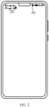
- a 4G signal strength indication icon 101 is displayed in a status bar of the mobile phone.
- the strength indication icon 101 can display a signal level in real time. For example, a larger quantity of displayed bars indicates a better received signal (or higher signal strength), and a smaller quantity of displayed bars indicates a weaker received signal (or lower signal strength).
- the mobile phone may alternatively simultaneously perform RSSI measurement on received signals of second generation (2nd generation, 2G), third generation (3rd generation, 3G), and 4G mobile communication networks.
- a strength indication icon 201 that can simultaneously indicate the signals of the 2G, 3G, and 4G mobile communication networks is displayed in the status bar of the mobile phone.
- the mobile phone may perform RSSI measurement on a received Wi-Fi signal.
- a Wi-Fi signal strength indication icon 102 is displayed in the status bar.
- a Wi-Fi signal strength indication icon 202 is displayed in the status bar.
- the strength indication icon can display a signal level in real time. For example, a larger quantity of displayed bars indicates a better received signal (or higher signal strength), and a smaller quantity of displayed bars indicates a weaker received signal (or lower signal strength).
- the RSSI measurement can only indicate the strength of the signal received by the mobile phone. Therefore, the strength indication icon displayed based on the RSSI measurement can only indicate the energy of the signal currently received by the mobile phone. For example, when a quantity of bars displayed in the strength indication icon decreases, it can only mean that the energy of the signal received by the mobile phone decreases.
- the energy of the signal received by the mobile phone may decrease because transmit power of a peer device (for example, a base station) decreases, signal attenuation between the mobile phone and the peer device increases (for example, a distance between the mobile phone and the peer device increases, or there is a building or wall between the mobile phone and the peer device), or because of an antenna performance exception of the mobile phone.
- the user cannot learn, from the strength indication icon displayed on the mobile phone, whether the antenna performance of the mobile phone deteriorates because the antenna is blocked. As a result, the user cannot remove an obstacle to the antenna of the mobile phone in time, and user experience of using the mobile phone is affected.
- an embodiment of this application provides an antenna blocking alarm method.
- the method may be applied to a communication device having an antenna.
- the method may include: The communication device obtains an attenuation value of an air interface loopback signal through an antenna, and determines, based on the attenuation value, whether the antenna of the communication device is blocked. After determining that the antenna of the communication device is blocked, the communication device may output, to a user, alarm information prompting that the antenna is blocked.
- the communication device may determine, based on the attenuation value of the signal, whether the antenna of the communication device is blocked.
- the alarm information is output to prompt the user that the antenna is blocked.
- the user can find, based on the alarm information, that the antenna of the communication device is blocked, and then remove an obstacle (such as a protective case and hands) in a timely manner, to improve user experience.
- the antenna blocking alarm method provided in this embodiment of this application may be applied to various communication devices, and the communication device may include a communication chip.
- the communication device may be a mobile phone, a tablet computer, a wearable device having a wireless communication capability, a television, a notebook computer, a desktop computer, or an augmented reality (augmented reality, AR)/virtual reality (virtual reality, VR) device.
- FIG. 3 is a schematic diagram of a structure of a communication device according to an embodiment of this application.
- the communication device includes a processor 310, an antenna system 1, an antenna system 2, a mobile communication module 320, a wireless communication module 330, and the like.
- the processor 310 may include one or more processing units.
- the processor 310 may include an application processor (application processor, AP), a modem processor, a graphics processing unit (graphics processing unit, GPU), an image signal processor (image signal processor, ISP), a controller, a memory, a video codec, a digital signal processor (digital signal processor, DSP), a baseband processor, and/or a neural-network processing unit (neural-network processing unit, NPU).
- Different processing units may be independent components, or may be integrated into one or more processors.
- the controller may be a nerve center and a command center of the communication device.
- the controller may generate an operation control signal based on instruction operation code and a time sequence signal, to complete control of instruction fetching and instruction execution.
- the memory may be further disposed in the processor 310, and is configured to store instructions and data.
- the memory in the processor 310 is a cache.
- the memory may store instructions or data just used or cyclically used by the processor 310. If the processor 310 needs to use the instructions or the data again, the processor may directly invoke the instructions or the data from the memory. This avoids repeated access, reduces waiting time of the processor 310, and improves system efficiency.
- a wireless communication function of the communication device is implemented by using the antenna system 1, the antenna system 2, the mobile communication module 320 (or referred to as the mobile communication chip), the wireless communication module 330 (or referred to as the wireless communication chip), or the like.
- the antenna system 1 and the antenna system 2 are configured to transmit and receive an electromagnetic wave signal.
- Each antenna in the communication device may be configured to cover one or more communication frequency bands. Different antennas may be further multiplexed, to improve antenna utilization.
- the antenna system 1 may be multiplexed as a diversity antenna of a wireless local area network.
- the antenna may be used in combination with a tuning switch.
- the mobile communication module 320 may provide a solution that is applied to the communication device and that is for wireless communication including 2G, 3G, 4G, 5G, and the like.
- the mobile communication module 320 may include at least one filter, a switch, a power amplifier, a low noise amplifier (low noise amplifier, LNA), and the like.
- the mobile communication module 320 may receive an electromagnetic wave through the antenna system 1, perform processing such as filtering or amplification on the received electromagnetic wave, and transmit the electromagnetic wave to the modem processor for demodulation.
- the mobile communication module 320 may further amplify a signal modulated by the modem processor, and convert the signal into an electromagnetic wave for radiation through the antenna system 1.
- at least some functional modules in the mobile communication module 320 may be disposed in the processor 310.
- at least some functional modules in the mobile communication module 320 may be disposed in a same component as at least some modules in the processor 310.
- the wireless communication module 330 may provide a solution that is applied to the communication device and that is for wireless communication including a wireless local area network (wireless local area network, WLAN) (for example, a Wi-Fi network), Bluetooth, a global navigation satellite system, and the like.
- the wireless communication module 330 may be one or more components integrating at least one communication processing module.
- the wireless communication module 330 receives an electromagnetic wave through the antenna system 2, performs frequency modulation and filtering processing on an electromagnetic wave signal, and sends a processed signal to the processor 310.
- the wireless communication module 330 may further receive a to-be-sent signal from the processor 310, perform frequency modulation and amplification on the signal, and convert the signal into an electromagnetic wave for radiation through the antenna system 2.
- the antenna system 1 and the mobile communication module 320 are coupled, and the antenna system 2 and the wireless communication module 330 are coupled, so that the communication device can communicate with a network and another device by using a wireless communication technology.
- the wireless communication technology may include a global system for mobile communications (global system for mobile communications, GSM), a general packet radio service (general packet radio service, GPRS), code division multiple access (code division multiple access, CDMA), wideband code division multiple access (wideband code division multiple access, WCDMA), time-division code division multiple access (time-division code division multiple access, TD-CDMA), long term evolution (long term evolution, LTE), Bluetooth, a GNSS, a WLAN technology, and the like.
- GSM global system for mobile communications
- GPRS general packet radio service
- code division multiple access code division multiple access
- CDMA wideband code division multiple access
- WCDMA wideband code division multiple access
- time-division code division multiple access time-division code division multiple access
- TD-CDMA
- the GNSS may include a global positioning system (global positioning system, GPS), a global navigation satellite system (global navigation satellite system, GLONASS), a BeiDou navigation satellite system (BeiDou navigation satellite system, BDS), a quasi-zenith satellite system (quasi-zenith satellite system, QZSS), and/or a satellite based augmentation system (satellite based augmentation system, SBAS).
- GPS global positioning system
- GLONASS global navigation satellite system
- BeiDou navigation satellite system BeiDou navigation satellite system
- BDS BeiDou navigation satellite system
- QZSS quasi-zenith satellite system
- SBAS satellite based augmentation system
- the structure shown in this embodiment does not constitute a specific limitation on the communication device.
- the communication device may include more or fewer components than those shown in the figure, or some components may be combined, or some components may be split, or there may be a different component layout.
- the components shown in the figure may be implemented by hardware, software, or a combination of software and hardware.
- the communication device may further include an external memory interface, an internal memory, a universal serial bus (universal serial bus, USB) interface, a charging management module, a power management module, a battery, an audio module, a speaker, a receiver, a microphone, a headset jack, a sensor module, a button, a motor, an indicator, a camera, a display screen, a subscriber identification module (subscriber identification module, SIM) card interface, and the like.
- the sensor module may include a pressure sensor, a gyro sensor, an acceleration sensor, a touch sensor, and the like.
- the wireless communication module 330 shown in FIG. 3 may be used as the communication chip to form a chipset with the processor 310, and the mobile communication module 320 may also be used as the communication chip to form a chipset with the processor 310.
- FIG. 4 is a schematic flowchart of an antenna blocking alarm method according to an embodiment of this application. As shown in FIG. 4 , the method includes the following S401 to S404.
- a communication chip obtains an attenuation value of a signal.
- the attenuation value may indicate attenuation of a strength value when the signal is received in comparison to a strength value when the signal is sent.
- the communication chip performs air interface loopback measurement through an antenna to obtain the attenuation value of the signal.
- the communication chip obtains an attenuation value of an air interface loopback signal through the antenna.
- antennas of the communication device include a first antenna and a second antenna (for example, the first antenna and the second antenna are two antennas in the antenna system 1 shown in FIG. 3 , or two antennas in the antenna system 2) that are individually connected to the communication chip, and the communication chip controls the first antenna to transmit a measurement signal, and receives the measurement signal through the second antenna. Then, the communication chip determines the attenuation value based on a difference between a strength value of the measurement signal received through the second antenna and a strength value of the measurement signal transmitted through the first antenna.
- a coverage frequency of the first antenna and a coverage frequency of the second antenna need to have an overlapping frequency band, to avoid that the air interface loopback measurement cannot be completed because the measurement signal transmitted through the first antenna is not within the coverage frequency of the second antenna and therefore cannot be received.
- a plurality of first antennas and/or second antennas may be separately disposed.
- a plurality of air interface loopbacks may be formed by using a plurality of antennas.
- the communication chip may separately transmit a measurement signal through the plurality of first antennas, so that one second antenna separately receives the measurement signal transmitted through the plurality of first antennas, to form the plurality of air interface loopbacks.
- the plurality of first antennas are a first antenna 1 and a first antenna 2, and one second antenna is a second antenna 1.
- the communication chip separately transmits a measurement signal through the first antenna 1 and the first antenna 2, and separately receives, through the second antenna 1, the measurement signal transmitted through the first antenna 1 and the measurement signal transmitted through the first antenna 2, to form two air interface loopbacks.
- the communication chip may separately transmit a measurement signal through the plurality of first antennas, so that the plurality of second antennas receive the corresponding measurement signal, to form a plurality of air interface loopbacks.
- the plurality of first antennas are a first antenna 1 and a first antenna 2
- the plurality of second antennas are a second antenna 1 and a second antenna 2.
- the communication chip separately transmits a measurement signal through the first antenna 1 and the first antenna 2, receives, through the second antenna 1, the measurement signal transmitted through the first antenna 1, and receives, through the second antenna 2, the measurement signal transmitted through the first antenna 2, to form two air interface loopbacks.
- the communication chip may transmit a measurement signal through one first antenna, and the plurality of second antennas separately receive the measurement signal, to form a plurality of air interface loopbacks.
- one first antenna is a first antenna 1
- the plurality of second antennas are a second antenna 1 and a second antenna 2.
- the communication chip transmits a measurement signal through the first antenna 1, and receives, through the second antenna 1 and the second antenna 2, the measurement signal transmitted through the first antenna 1, to form two air interface loopbacks.
- the communication chip when the communication chip performs air interface loopback measurement by forming a plurality of air interface loopbacks, the communication chip may calculate first attenuation values corresponding to different air interface loopbacks, and then determine a final attenuation value based on the first attenuation values, to improve accuracy of the determined attenuation value. For example, the communication chip may use an average value of the plurality of obtained first attenuation values as the finally determined attenuation value.
- the communication chip when the communication chip separately transmits the measurement signal through the first antenna 1 and the first antenna 2, receives, through the second antenna 1, the measurement signal transmitted through the first antenna 1, and receives, through the second antenna 2, the measurement signal transmitted through the first antenna 2, to form the two air interface loopbacks, the communication chip determines an attenuation value 1 based on a difference between a strength value of the measurement signal transmitted through the first antenna 1 and a strength value of the measurement signal received through the second antenna 1 and transmitted through the first antenna 1. The communication chip then determines an attenuation value 2 based on a difference between a strength value of the measurement signal transmitted through the first antenna 2 and a strength value of the measurement signal received through the second antenna 1 and transmitted through the first antenna 2. Then, the communication chip determines a final attenuation value based on an average value of the attenuation value 1 and the attenuation value 2.
- the communication chip when the communication chip performs air interface loopback measurement by forming a plurality of air interface loopbacks, the communication chip may alternatively calculate and determine an attenuation value based on an average value of strength values of a measurement signal transmitted through the first antennas, and an average value of strength values of the measurement signal received through the second antennas.
- the communication chip when the communication chip separately transmits the measurement signal through the first antenna 1 and the first antenna 2, receives, through the second antenna 1, the measurement signal transmitted through the first antenna 1, and receives, through the second antenna 2, the measurement signal transmitted through the first antenna 2, to form the two air interface loopbacks, the communication chip calculates an average value (for example, referred to as a first average value) of a strength value of the measurement signal transmitted through the first antenna 1 and a strength value of the measurement signal transmitted through the first antenna 2. The communication chip then calculates an average value (for example, referred to as a second average value) of a strength value of the measurement signal received through the second antenna 1 and a strength value of the measurement signal received through the second antenna 2. Then, the communication chip calculates and obtains an attenuation value based on a difference between the first average value and the second average value.
- a first average value for example, referred to as a strength value of the measurement signal transmitted through the first antenna 1
- a strength value of the measurement signal transmitted through the first antenna 2 a strength
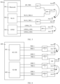
- FIG. 5 is a schematic composition diagram of a wireless communication subsystem according to an embodiment of this application.
- the wireless communication subsystem includes a communication chip 500, a switch (switch, SW), and an antenna (Ant).
- the communication chip 500 is a Wi-Fi/Bluetooth/GNSS chip.
- the communication chip 500 integrates a Bluetooth module 501, a Wi-Fi module 502, and a GNSS module 503.
- a transmit/receive channel (BT_TRX) of the Bluetooth module 501 is connected to an Ant 0 through an SW 1, and the SW 1 is connected to an Ant 1 through an SW 2.
- a transmit/receive channel (Wi-Fi_TRX) 0 of the Wi-Fi module 502 is connected to the Ant 1 through the SW 2, and a Wi-Fi_TRX 1 of the Wi-Fi module 502 is connected to an Ant 2 and an Ant 3 through an SW 3.
- a transmit channel (GNSS_TX) and a first receive channel (GNSS_L1RX) of the GNSS module 503 are connected to an Ant 4 through an SW 4, and a second receive channel (GNSS_L5RX) is connected to an Ant 5.
- the communication chip 500 may transmit and receive a signal through a correspondingly connected antenna over a transmit and receive channel, may transmit a signal through a correspondingly connected antenna over a transmit channel, and may receive a signal through a correspondingly connected antenna over a receive channel.
- the Wi-Fi module 502 of the communication chip 500 measures a strength value of the received measurement signal, for example, obtains a second strength value.
- the Wi-Fi module 502 of the communication chip 500 may obtain the first strength value from the Bluetooth module 501, and obtain an attenuation value of the measurement signal through calculation based on the first strength value and the second strength value. For example, a difference between the second strength value and the first strength value may be determined as the attenuation value of the measurement signal. In this way, air interface loopback measurement is completed.
- FIG. 6 is a schematic composition diagram of another wireless communication subsystem according to an example, which is not an embodiment of the present invention but helpful for understanding certain aspects thereof.
- the wireless communication subsystem includes a communication chip 600, and the communication chip 600 is a 4G LTE/5G NR modem chip that integrates a 4G long term evolution (long term evolution, LTE) module 601 and a 5G new radio (new radio, NR) module 602.
- a transmit channel (TRX) 1 and a receive channel (DRX) 1 of the 4G LTE module 601 are connected to an antenna (Ant) 0 and an Ant 1 through a double pole double throw switch (DPDT) 1.
- TRX transmit channel
- DRX receive channel
- the 5G NR module 602 of the communication chip 600 may generate a monophonic signal or a modulation signal of specific strength, for example, a first strength value, as a measurement signal.
- the 5G NR module 602 of the communication chip 600 controls the DPDT 3 to transmit the measurement signal through the Ant 4.
- the 5G NR module 602 of the communication chip 600 controls the DPDT 4 to separately receive the measurement signal through the Ant 5 and the Ant 6, to form two air interface loopbacks. Then, the 5G NR module 602 of the communication chip 600 measures a strength value of the measurement signal received through the Ant 5, for example, obtains a second strength value, and measures a strength value of the measurement signal received through the Ant 6, for example, obtains a third strength value.
- the 5G NR module 602 of the communication chip 600 may determine a difference between the first strength value and the second strength value as a first attenuation value, and determine a difference between the first strength value and the third strength value as a second attenuation value. Finally, a final attenuation value is determined based on an average value of the first attenuation value and the second attenuation value, and air interface loopback measurement is completed.
- the communication chip may alternatively be a 4G LTE chip, a 5G NR chip, or the like that is independently disposed.
- air interface loopback measurement refer to an air interface loopback measurement process of the communication chip shown in FIG. 6 . Details are not described herein again.
- the first strength value, the second strength value, and the third strength value may be RSSI values respectively corresponding to the measurement signal.
- the communication chip may obtain an RSSI value by performing RSSI detection on the received measurement signal. This is not limited herein.
- the communication device determines whether differences between a plurality of attenuation values consecutively obtained within the second preset duration and the attenuation calibration value are all greater than the second preset threshold. If the differences between the plurality of attenuation values consecutively obtained within the second preset duration and the attenuation calibration value are all greater than the second preset threshold, it is determined that the antenna is blocked.
- a preset threshold for example, a second preset threshold
- a preset threshold for example, 20 dB
- a difference between a previously obtained attenuation value and the attenuation calibration value is less than the preset threshold it may be determined, with reference to a status indication of the communication device (for example, a landscape display indication of a mobile phone), that the antenna is blocked due to an abnormal holding posture of a user.
- the attenuation calibration value may be an attenuation value of a signal obtained when the antenna is not blocked (for example, when the communication device is bare), for example, an attenuation value that is of a measurement signal and that is determined and obtained through air interface loopback measurement when the communication device is bare.
- the communication chip indicates a processor to output, to the user, alarm information prompting that the antenna is blocked.
- the alarm information may include a reason why the antenna is blocked and that is determined by the communication chip. For determining the reason why the antenna is blocked, refer to the description in S402.
- S404 The processor controls the communication device to output the alarm information.
- the alarm information output by the communication device may be an icon indicating that the antenna is blocked, and/or a pop-up message indicating that the antenna is blocked.
- the processor controls the communication device to display the pop-up message.
- the pop-up message may be "The antenna of the mobile phone is blocked".
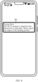
- the processor may further determine, based on a specific communication chip from which a received indication comes, that a specific antenna is blocked. Then, the alarm information is output based on a reason that is indicated by the communication chip and why the antenna is blocked, and the determined blocked antenna, to prompt a user why a specific antenna is blocked. For example, when the communication chip indicates that the antenna is blocked by the protective case, and the indication is sent by the Wi-Fi module 502 of the communication chip 500 shown in FIG. 5 , the processor may determine that a Wi-Fi antenna is blocked by the protective case. The processor may control the communication device to display a pop-up message. As shown in FIG.
- a pop-up window message 701 may be "The Wi-Fi antenna is detected to be blocked for a long time. Please check the blocking impact of the phone case!".
- the processor may determine that a Wi-Fi antenna is blocked due to the impact of the holding posture.
- the processor may control the communication device to display a pop-up message.
- a pop-up window message 801 may be "The Wi-Fi antenna is detected to be blocked for a short time. Please check the impact of the holding posture!.
- the processor may determine that a Wi-Fi antenna is blocked by the protective case.
- the processor may control the communication device to display an icon indicating that the Wi-Fi antenna is blocked.
- a first icon 901 indicating a Wi-Fi signal is displayed in a status bar of the mobile phone.
- a second icon 902 is displayed in the status bar of the mobile phone. The second icon 902 indicates that the Wi-Fi antenna is blocked.
- the communication chip may determine, based on the attenuation value of the signal when the signal is received, whether the communication device is blocked, and indicate the processor of the communication device to control the communication device to output the alarm information, to prompt the user that the antenna is blocked.
- the user can find, based on the alarm information, that the antenna of the communication device is blocked, and then remove an obstacle (such as a protective case and hands) in a timely manner, to improve user experience.
- the antenna may include a first antenna and a second antenna.
- the transceiver module 1002 may be configured to transmit, based on control of the control module, a measurement signal through the first antenna, receive the measurement signal looped back to the second antenna, and measure a strength value of the looped back measurement signal.
- the control module 1001 may be specifically configured to determine the attenuation value based on a strength value of the measurement signal and the strength value of the looped back measurement signal.
- the transceiver module 1002 may implement functions of the transceiver module 1002 by using the baseband module 1003 and the radio frequency module 1004.
- the baseband module 1003 may be configured to generate a measurement signal based on control of the control module 1001.
- the radio frequency module 1004 may be configured to transmit the measurement signal through the first antenna, and receive the measurement signal looped back to the second antenna.
- the baseband module 1003 may be further configured to measure a strength value of the looped back measurement signal.
- the communication chip 500 shown in FIG. 5 is used as an example.
- the communication chip includes a B-central processing unit (central processing unit, CPU) 1101 (that is, a first control module) and a W-CPU 1102 (that is, a second control module) that are connected to each other, a GNSS baseband module 1103 and a GNSS radio frequency module 1104 that are connected to each other, a Bluetooth baseband module 1105 and a Bluetooth radio frequency module 1106 that are connected to each other, and a Wi-Fi baseband module 1107 and a Wi-Fi radio frequency module 1108 that are connected to each other.
- CPU central processing unit
- W-CPU 1102 that is, a second control module
- the Bluetooth baseband module 1105 and the GNSS baseband module 1103 are separately connected to the B-CPU 1101, and the Wi-Fi baseband module 1107 is connected to the W-CPU 1102.
- the B-CPU 1101, the Bluetooth baseband module 1105, and the Bluetooth radio frequency module 1106 forms the Bluetooth module 501 of the communication chip 500 shown in FIG. 5 .
- the B-CPU 1101, the GNSS baseband module 1103, and the GNSS radio frequency module 1104 may form the GNSS module 503 of the communication chip 500 shown in FIG. 5 .
- the W-CPU 1102, the Wi-Fi baseband module 1107, and the Wi-Fi radio frequency module 1108 forms the Wi-Fi module 502 of the communication chip 500 shown in FIG. 5 .
- the B-CPU 1101 controls the Bluetooth baseband module 1105 to generate a monophonic signal or a modulation signal of specific strength, for example, a first strength value, as a measurement signal.
- the Bluetooth radio frequency module 1106 may amplify the measurement signal to a radio frequency band, and transmit the measurement signal through the Ant 0 shown in FIG. 5 .
- the Wi-Fi radio frequency module 1108 receives the measurement signal through the Ant 2 shown in FIG. 5 , and converts the measurement signal to a baseband frequency band.
- the Wi-Fi baseband module 1107 may measure a strength value of the measurement signal of the baseband frequency band, for example, obtain a second strength value. Then, the W-CPU 1102 may obtain the first strength value from the B-CPU 1101, and obtain the second strength value from the Wi-Fi baseband module 1107. A difference between the first strength value and a second strength value that is obtained by converting post-gain strength values generated by the Bluetooth radio frequency module 1106 and the Wi-Fi radio frequency module 1108, is determined as the attenuation value of the measurement signal, and air interface loopback measurement is completed.
- the communication chip 600 shown in FIG. 6 is used as an example.
- the communication chip may include a cellular processor (cellular processor) 1201 (that is, a control module), a baseband module, a radio frequency module (which may be integrated into one module, that is, a baseband+radio frequency module 1202), a 4G power/low noise amplifier (4G external PA/external LNA, 4G ePA/eLNA) 1203, and a 5G power/low noise amplifier (5G external PA/external LNA, 5G ePA/eLNA) 1204.
- a cellular processor cellular processor
- baseband module that is, a control module
- a radio frequency module which may be integrated into one module, that is, a baseband+radio frequency module 1202
- 4G power/low noise amplifier (4G external PA/external LNA, 4G ePA/eLNA) 1203
- 5G power/low noise amplifier 5G external PA/external LNA, 5G ePA/eLNA
- the cellular processor 1201, the baseband+radio frequency module 1202, and the 4G ePA/eLNA 1203 may form the 4G LTE module 601 of the communication chip 600 shown in FIG. 6 .
- the cellular processor 1201, the baseband+radio frequency module 1202, and the 5G ePA/eLNA 1204 may form the 5G NR module 602 of the communication chip 600 shown in FIG. 6 .
- the foregoing functions of the communication chip 600 shown in FIG. 6 may be implemented by using the communication chip.
- the cellular processor 1201 may control the baseband module in the baseband+radio frequency module 1202 to generate a monophonic signal or a modulation signal of specific strength, for example, a first strength value, as a measurement signal, and the radio frequency module amplifies the measurement signal to a radio frequency band. Then, the 4G ePA/eLNA 1203 further amplifies the measurement signal and separately transmits the measurement signal through the Ant 0 and the Ant 1 shown in FIG. 6 . Then, the 4G ePA/eLNA 1203 may receive, through the Ant 2 shown in FIG. 6 , the measurement signal separately transmitted through the Ant 0 and the Ant 1, to form two air interface loopbacks.
- a monophonic signal or a modulation signal of specific strength for example, a first strength value
- the radio frequency module in the baseband+radio frequency module 1202 may convert the separately received measurement signals to a baseband frequency band, and then the baseband module separately measures strength values of the two received measurement signals, for example, obtains a second strength value and a third strength value.
- the cellular processor 1201 may obtain the second strength value and the third strength value, obtain a first attenuation value based on a difference between the first strength value and the second strength value, and obtain a second attenuation value based on a difference between the first strength value and the third strength value. Finally, a final attenuation value is determined based on an average value of the first attenuation value and the second attenuation value, and air interface loopback measurement is completed.
- control module 1001 may be specifically configured to periodically obtain a plurality of attenuation values based on a preset periodicity, and determine, based on the plurality of obtained attenuation values, whether the antenna is blocked.
- control module 1001 may be specifically configured to: determine whether a difference between the attenuation value within first preset duration and an attenuation calibration value is greater than a first preset threshold; if the difference between the attenuation value within the first preset duration and the attenuation calibration value is greater than the first preset threshold, determine that the antenna is blocked; and if the difference between the attenuation value within the first preset duration and the attenuation calibration value is not greater than the first preset threshold, determine that the antenna is not blocked.
- control module 1001 may be specifically configured to: when a difference between the attenuation value obtained before second preset duration and an attenuation calibration value is less than a second preset threshold, determine whether differences between a plurality of attenuation values consecutively obtained within the second preset duration and the attenuation calibration value are all greater than the second preset threshold; if the differences between the plurality of attenuation values consecutively obtained within the second preset duration and the attenuation calibration value are all greater than the second preset threshold, determine that the antenna is blocked; and if the differences between the plurality of attenuation values consecutively obtained within the second preset duration and the attenuation calibration value are not all greater than the second preset threshold, determine that the antenna is not blocked.
- control module 1001 may be specifically configured to determine, based on status indication information, that the antenna is blocked due to an abnormal holding posture, where the status indication information indicates that a communication device is in a landscape mode.
- division into the units or modules is merely logical function division. In actual implementation, all or some of the units or modules may be integrated into one physical entity, or may be physically separated.
- each unit may be an independently disposed processing element, or may be integrated into a chip for implementation.
- the unit in the communication chip may be one or more integrated circuits configured to implement the foregoing methods, for example, one or more ASICs, one or more DSPs, one or more FPGAs, or a combination of at least two of the integrated circuit forms.
- the units may be integrated and implemented in a form of a system-on-a-chip (system-on-a-chip, SOC).
- SOC system-on-a-chip
- An embodiment of this application may further provide a communication device.
- the communication device may include a processor, and a memory configured to store executable instructions of the processor.
- the processor When the processor is configured to execute the instructions, the communication device is enabled to implement the antenna blocking alarm method described in the foregoing embodiments.
- the memory may be located inside the communication device, or may be located outside the communication device.
- An embodiment of this application further provides a computer program product, including computer instructions run by a communication device, such as the foregoing communication device.
- An embodiment of this application further provides a computer-readable storage medium, and the computer-readable storage medium stores computer program instructions.
- the computer program instructions are executed by a communication device, the communication device is enabled to implement the antenna blocking alarm method described in the foregoing method embodiments.
Landscapes
- Engineering & Computer Science (AREA)
- Computer Networks & Wireless Communication (AREA)
- Physics & Mathematics (AREA)
- Electromagnetism (AREA)
- Signal Processing (AREA)
- Quality & Reliability (AREA)
- Telephone Function (AREA)
- Support Of Aerials (AREA)
- Transceivers (AREA)
- Monitoring And Testing Of Transmission In General (AREA)
Claims (13)
- Antennenblockierungswarnverfahren, das durch einen Kommunikationschip (500) oder eine Kommunikationsvorrichtung, die den Kommunikationschip (500) umfasst, ausgeführt wird, wobei das Verfahren Folgendes umfasst:Erlangen (S401) eines Dämpfungswerts eines Rückschleifsignals der Luftschnittstelle über eine Antenne;Bestimmen (S402), basierend auf dem Dämpfungswert, ob die Antenne blockiert ist; undwenn bestimmt wird, dass die Antenne blockiert ist, Angeben (S403), durch den Kommunikationschip (500), eines Prozessors zum Ausgeben von Alarminformationen an einen Benutzer, die auslösen,dass die Antenne blockiert wird, oder Ausgeben, durch die Kommunikationsvorrichtung, von Alarminformationen an den Benutzer, die auslösen, dass die Antenne blockiert wird;wobei die Antenne eine erste Antenne und eine zweite Antenne umfasst; unddas Erlangen (S401) eines Dämpfungswerts eines Rückschleifsignals der Luftschnittstelle über eine Antenne Folgendes umfasst:Übertragen eines Messsignals über die erste Antenne und Empfangen des Messsignals, das zu der zweiten Antenne zurückgeschleift wird; undBestimmen des Dämpfungswerts basierend auf einem Festigkeitswert des Messsignals und einem Festigkeitswert des zurückgeschleiften Messsignals;wobei der Kommunikationschip (500) ein Bluetooth-Modul (501) und ein drahtloses Wireless-Fidelity(Wi-Fi)-Netzwerkmodul (502) umfasst und das Übertragen eines Messsignals über die erste Antenne und das Empfangen des Messsignals, das zu der zweiten Antenne zurückgeschleift wird, Folgendes umfasst:wenn ein Wi-Fi-Dienst des Kommunikationschips (500) inaktiv ist, Generieren, durch das Bluetooth-Modul (501), eines monophonen Signals oder eines Modulationssignals spezifischer Stärke als das Messsignal;Übertragen, durch das Bluetooth-Modul (501), des Messsignals über die erste Antenne;Empfangen, durch das Wi-Fi-Netzwerkmodul (502), des Messsignals, das zu der zweiten Antenne zurückgeschleift wird; undBestimmen, durch das Wi-Fi-Netzwerkmodul (502), des Dämpfungswerts basierend auf dem Festigkeitswert des Messsignals und dem Festigkeitswert des zurückgeschleiften Messsignals.
- Verfahren nach Anspruch 1, wobei
das Erlangen (S401) eines Dämpfungswerts eines Rückschleifsignals der Luftschnittstelle über eine Antenne Folgendes umfasst:periodisches Erlangen einer Vielzahl von Dämpfungswerten basierend auf einer vorgegebenen Periodizität; unddas Bestimmen (S402), basierend auf dem Dämpfungswert, ob die Antenne blockiert ist, Folgendes umfasst:
Bestimmen, basierend auf der Vielzahl von erlangten Dämpfungswerten, ob die Antenne blockiert ist. - Verfahren nach Anspruch 1 oder 2, wobei das Bestimmen (S402), basierend auf dem Dämpfungswert, ob die Antenne blockiert ist, Folgendes umfasst:Bestimmen, ob eine Differenz zwischen dem Dämpfungswert innerhalb der ersten vorgegebenen Dauer und einem Dämpfungskalibrierungswert größer als ein erster vorgegebener Schwellenwert ist;falls die Differenz zwischen dem Dämpfungswert innerhalb der ersten vorgegebenen Dauer und dem Dämpfungskalibrierungswert größer als der erste vorgegebene Schwellenwert ist, Bestimmen, dass die Antenne blockiert ist; undfalls die Differenz zwischen dem Dämpfungswert innerhalb der ersten vorgegebenen Dauer und dem Dämpfungskalibrierungswert nicht größer als der erste vorgegebene Schwellenwert ist, Bestimmen, dass die Antenne nicht blockiert ist.
- Verfahren nach Anspruch 2, wobei das Bestimmen (S402), basierend auf dem Dämpfungswert, ob die Antenne blockiert ist, Folgendes umfasst:wenn eine Differenz zwischen dem Dämpfungswert, der vor der zweiten vorgegebenen Dauer erlangt wird, und einem Dämpfungskalibrierungswert kleiner als ein zweiter vorgegebener Schwellenwert ist, Bestimmen, ob Differenzen zwischen einer Vielzahl von Dämpfungswerten, die innerhalb der zweiten vorgegebenen Dauer nacheinander erlangt werden, und dem Dämpfungskalibrierungswert alle größer als der zweite vorgegebene Schwellenwert sind;falls die Differenzen zwischen der Vielzahl von Dämpfungswerten, die innerhalb der zweiten vorgegebenen Dauer nacheinander erlangt werden, und dem Dämpfungskalibrierungswert alle größer als der zweite vorgegebene Schwellenwert sind, Bestimmen, dass die Antenne blockiert ist; undfalls die Differenzen zwischen der Vielzahl von Dämpfungswerten, die innerhalb der zweiten vorgegebenen Dauer nacheinander erlangt werden, und dem Dämpfungskalibrierungswert nicht alle größer als der zweite vorgegebene Schwellenwert sind, Bestimmen, dass die Antenne nicht blockiert ist.
- Verfahren nach einem der Ansprüche 1 bis 4, wobei das Ausgeben, durch die Kommunikationsvorrichtung, der Alarminformationen an den Benutzer, die auslösen, dass die Antenne blockiert ist, Folgendes umfasst:
Anzeigen, durch die Kommunikationsvorrichtung, einer Benutzerschnittstelle, wobei die Benutzerschnittstelle Folgendes umfasst: ein Symbol, das anzeigt, dass die Antenne blockiert ist, und/oder eine Popup-Nachricht, die anzeigt, dass die Antenne blockiert ist. - Verfahren nach einem der Ansprüche 1 bis 4, wobei das Verfahren ferner Folgendes umfasst:Anzeigen, durch die Kommunikationsvorrichtung, eines ersten Symbols, wobei das erste Symbol die Stärke des Signals anzeigt, das durch die Kommunikationsvorrichtung empfangen wird; unddas Ausgeben, durch die Kommunikationsvorrichtung, von Alarminformationen an einen Benutzer, die auslösen, dass die Antenne blockiert wird, Folgendes umfasst:
Aktualisieren und Anzeigen, durch die Kommunikationsvorrichtung, des ersten Symbols als ein zweites Symbol, wobei das zweite Symbol anzeigt, dass die Antenne blockiert ist. - Kommunikationschip (500) für eine Kommunikationsvorrichtung, die eine Antenne umfasst, wobei die Antenne eine erste Antenne und eine zweite Antenne umfasst, und wobei der Kommunikationschip (500) Folgendes umfasst:ein Steuermodul (1001), das dazu konfiguriert ist, einen Dämpfungswert eines Rückschleifsignals der Luftschnittstelle über die Antenne zu erlangen; basierend auf dem Dämpfungswert zu bestimmen, ob die Antenne blockiert ist; und wenn bestimmt wird, dass die Antenne blockiert ist, einen Prozessor (310) zum Ausgeben von Alarminformationen an einen Benutzer anzugeben, die auslösen, dass die Antenne blockiert wird;wobei der Kommunikationschip ferner ein Sende-Empfängermodul (1002) umfasst;das Sende-Empfängermodul (1002) dazu konfiguriert ist, basierend auf einer Steuerung des Steuermoduls (1001) ein Messsignal über die erste Antenne zu übertragen, das zu der zweiten Antenne zurückgeschleiften Messsignal zu empfangen und einen Festigkeitswert des zurückgeschleiften Messsignals zu messen; unddas Steuermodul (1001) speziell dazu konfiguriert ist, den Dämpfungswert basierend auf einem Festigkeitswert des Messsignals und dem Festigkeitswert des zurückgeschleiften Messsignals zu bestimmen;wobei das Sende-Empfängermodul (1002) ein Basisbandmodul (1003) und ein Funkfrequenzmodul (1004) umfasst;das Basisbandmodul (1003) dazu konfiguriert ist, das Messsignal basierend auf der Steuerung des Steuermoduls (1001) zu generieren;das Funkfrequenzmodul (1004) dazu konfiguriert ist, das Messsignal über die erste Antenne zu übertragen und das zu der zweiten Antenne zurückgeschleifte Messsignal zu empfangen; unddas Basisbandmodul (1003) ferner dazu konfiguriert ist, den Festigkeitswert des zurückgeschleiften Messsignals zu messen;wobei das Steuermodul (1001) ein erstes Steuermodul (1101) und ein zweites Steuermodul (1102) umfasst, das Basisbandmodul (1003) ein Bluetooth-Basisbandmodul (1105) und ein Wireless-Fidelity(Wi-Fi) -Basisbandmodul (1107) umfasst, und das Funkfrequenzmodul (1104) ein Bluetooth-Funkfrequenzmodul (1106) und ein Wi-Fi-Funkfrequenzmodul (1108) umfasst;wenn ein Wi-Fi-Dienst des Kommunikationschips (500) inaktiv ist, das erste Steuermodul (1101) dazu konfiguriert ist, das Bluetooth-Basisbandmodul (1105) zu steuern, um ein monophones Signal oder ein Modulationssignal einer bestimmten Stärke als das Messsignal zu generieren;das Bluetooth-Basisbandmodul (1105) dazu konfiguriert ist, das Messsignal basierend auf einer Steuerung des ersten Steuermoduls (1101) zu generieren;das Bluetooth-Funkfrequenzmodul (1106) dazu konfiguriert ist, das Messsignal über die erste Antenne zu übertragen;das Wi-Fi-Funkfrequenzmodul (1108) dazu konfiguriert ist, das zu der zweiten Antenne zurückgeschleifte Messsignal zu empfangen;das Wi-Fi-Basisbandmodul (1107) dazu konfiguriert ist, den Festigkeitswert des zurückgeschleiften Messsignals zu messen; unddas zweite Steuermodul (1102) dazu konfiguriert ist, den Dämpfungswert basierend auf dem Festigkeitswert des Messsignals und dem Festigkeitswert des zurückgeschleiften Messsignals zu bestimmen.
- Kommunikationschip (500) nach Anspruch 7, wobei der Kommunikationschip (500), der dazu konfiguriert ist, einen Dämpfungswert eines Rückschleifsignals der Luftschnittstelle über eine Antenne zu erlangen, Folgendes umfasst:der Kommunikationschip (500) ist dazu konfiguriert, periodisch eine Vielzahl von Dämpfungswerten basierend auf einer vorgegebenen Periodizität zu erlangen und basierend auf dem Dämpfungswert zu bestimmen, ob die Antenne blockiert ist,wobei der Kommunikationschip (500), der dazu konfiguriert ist, basierend auf dem Dämpfungswert zu bestimmen, ob die Antenne blockiert ist, Folgendes umfasst:
der Kommunikationschip (500) ist dazu konfiguriert, basierend auf der Vielzahl von erlangten Dämpfungswerten zu bestimmen, ob die Antenne blockiert ist. - Kommunikationschip (500) nach Anspruch 7 oder 8, wobei der Kommunikationschip (500), der dazu konfiguriert ist, basierend auf dem Dämpfungswert zu bestimmen, ob die Antenne blockiert ist, Folgendes umfasst:der Kommunikationschip (500) ist dazu konfiguriert, zu bestimmen, ob eine Differenz zwischen dem Dämpfungswert innerhalb der ersten vorgegebenen Dauer und einem Dämpfungskalibrierungswert größer als ein erster vorgegebener Schwellenwert ist;falls die Differenz zwischen dem Dämpfungswert innerhalb der ersten vorgegebenen Dauer und dem Dämpfungskalibrierungswert größer als der erste vorgegebene Schwellenwert ist, ist der Kommunikationschip (500) dazu konfiguriert, zu bestimmen, dass die Antenne blockiert ist; undfalls die Differenz zwischen dem Dämpfungswert innerhalb der ersten vorgegebenen Dauer und dem Dämpfungskalibrierungswert nicht größer als der erste vorgegebene Schwellenwert ist, ist der Kommunikationschip (500) dazu konfiguriert, zu bestimmen, dass die Antenne nicht blockiert ist.
- Kommunikationschip (500) nach Anspruch 8, wobei der Kommunikationschip (500), der dazu konfiguriert ist, basierend auf dem Dämpfungswert zu bestimmen, ob die Antenne blockiert ist, Folgendes umfasst:wenn eine Differenz zwischen dem Dämpfungswert, der vor der zweiten vorgegebenen Dauer erlangt wird, und einem Dämpfungskalibrierungswert kleiner als ein zweiter vorgegebener Schwellenwert ist, der Kommunikationschip (500) dazu konfiguriert ist, zu bestimmen, ob Differenzen zwischen einer Vielzahl von Dämpfungswerten, die innerhalb der zweiten vorgegebenen Dauer nacheinander erlangt werden, und dem Dämpfungskalibrierungswert alle größer als der zweite vorgegebene Schwellenwert sind;falls die Differenzen zwischen der Vielzahl von Dämpfungswerten, die innerhalb der zweiten vorgegebenen Dauer nacheinander erlangt werden, und dem Dämpfungskalibrierungswert alle größer als der zweite vorgegebene Schwellenwert sind, der Kommunikationschip (500) dazu konfiguriert ist, zu bestimmen, dass die Antenne blockiert ist; undfalls die Differenzen zwischen der Vielzahl von Dämpfungswerten, die innerhalb der zweiten vorgegebenen Dauer nacheinander erlangt werden, und dem Dämpfungskalibrierungswert nicht alle größer als der zweite vorgegebene Schwellenwert sind, der Kommunikationschip (500) dazu konfiguriert ist, zu bestimmen, dass die Antenne nicht blockiert ist.
- Kommunikationsvorrichtung, umfassend eine Antenne und einen Chipsatz, wobei die Antenne eine erste Antenne und eine zweite Antenne umfasst, wobei der Chipsatz den Kommunikationschip (500) nach einem der Ansprüche 7 bis 10 und einen Prozessor (310) umfasst, und wobei der Prozessor (310) dazu konfiguriert ist, die Kommunikationsvorrichtung basierend auf einer Angabe des Kommunikationschips (500) zum Ausgeben der Alarminformationen an den Benutzer zu steuern, die auslösen, dass die Antenne blockiert wird.
- Computerlesbares Speichermedium, auf dem Anweisungen gespeichert sind, die bei Ausführung durch die Kommunikationsvorrichtung nach Anspruch 11 bewirken, dass die Kommunikationsvorrichtung das Verfahren nach einem der Ansprüche 1 bis 6 durchführt.
- Computerprogrammprodukt, umfassend Anweisungen, welche bei Ausführung durch die Kommunikationsvorrichtung nach Anspruch 11 bewirken, dass die Kommunikationsvorrichtung das Verfahren nach einem der Ansprüche 1 bis 6 durchführt.
Applications Claiming Priority (1)
| Application Number | Priority Date | Filing Date | Title |
|---|---|---|---|
| PCT/CN2021/074255 WO2022160215A1 (zh) | 2021-01-28 | 2021-01-28 | 一种天线遮挡告警方法、通信芯片及设备 |
Publications (3)
| Publication Number | Publication Date |
|---|---|
| EP4274203A1 EP4274203A1 (de) | 2023-11-08 |
| EP4274203A4 EP4274203A4 (de) | 2024-02-28 |
| EP4274203B1 true EP4274203B1 (de) | 2025-04-23 |
Family
ID=82652891
Family Applications (1)
| Application Number | Title | Priority Date | Filing Date |
|---|---|---|---|
| EP21921823.7A Active EP4274203B1 (de) | 2021-01-28 | 2021-01-28 | Antennenblockierungswarnverfahren, kommunikationschip und vorrichtung |
Country Status (4)
| Country | Link |
|---|---|
| US (1) | US20230370176A1 (de) |
| EP (1) | EP4274203B1 (de) |
| CN (1) | CN116114240B (de) |
| WO (1) | WO2022160215A1 (de) |
Family Cites Families (14)
| Publication number | Priority date | Publication date | Assignee | Title |
|---|---|---|---|---|
| US5959570A (en) * | 1997-11-21 | 1999-09-28 | Raytheon Company | Automotive forward looking sensor blockage detection system and related techniques |
| US11177997B2 (en) * | 2014-02-21 | 2021-11-16 | Commscope Technologies Llc | Distributed antenna system transport link quality measurement |
| US10162046B2 (en) * | 2016-03-17 | 2018-12-25 | Valeo Radar Systems, Inc. | System and method for detecting blockage in an automotive radar |
| CN105959464B (zh) * | 2016-04-22 | 2018-12-11 | 广东欧珀移动通信有限公司 | 一种终端信号强度的提醒方法及装置 |
| CN107690823B (zh) * | 2016-09-26 | 2021-05-25 | 深圳市大疆创新科技有限公司 | 一种通信质量检测方法、装置及设备 |
| CN106911848B (zh) * | 2017-02-21 | 2020-03-31 | Oppo广东移动通信有限公司 | 输出提示消息的方法与终端设备 |
| CN109391307B (zh) * | 2017-08-04 | 2021-08-24 | 维沃移动通信有限公司 | 一种天线波束侦测系统、方法及移动终端 |
| US20190089471A1 (en) * | 2017-09-21 | 2019-03-21 | Qualcomm Incorporated | System and method for mmwave massive array self-testing |
| KR102411282B1 (ko) * | 2017-12-28 | 2022-06-21 | 삼성전자주식회사 | 차폐를 탐지하는 방법 및 전자 장치 |
| CN108989567B (zh) * | 2018-08-02 | 2021-03-02 | Oppo广东移动通信有限公司 | 信息提醒方法、存储介质及电子设备 |
| US10484033B1 (en) * | 2018-08-03 | 2019-11-19 | Qualcomm Incorporated | User interface to enhance millimeter wave (mmWav) communications |
| US11122512B2 (en) * | 2018-12-21 | 2021-09-14 | Qualcomm Incorporated | Modem-based form factor sensor |
| US11115138B2 (en) * | 2019-08-19 | 2021-09-07 | Apple Inc. | Method for antenna occlusion detection |
| CN111669207B (zh) * | 2020-06-22 | 2022-07-12 | 广东虹勤通讯技术有限公司 | 一种天线切换方法、装置、终端及存储介质 |
-
2021
- 2021-01-28 CN CN202180057481.8A patent/CN116114240B/zh active Active
- 2021-01-28 EP EP21921823.7A patent/EP4274203B1/de active Active
- 2021-01-28 WO PCT/CN2021/074255 patent/WO2022160215A1/zh not_active Ceased
-
2023
- 2023-07-27 US US18/360,272 patent/US20230370176A1/en active Pending
Also Published As
| Publication number | Publication date |
|---|---|
| CN116114240A8 (zh) | 2023-08-01 |
| EP4274203A4 (de) | 2024-02-28 |
| EP4274203A1 (de) | 2023-11-08 |
| WO2022160215A1 (zh) | 2022-08-04 |
| CN116114240B (zh) | 2025-03-18 |
| CN116114240A (zh) | 2023-05-12 |
| US20230370176A1 (en) | 2023-11-16 |
Similar Documents
| Publication | Publication Date | Title |
|---|---|---|
| US10673514B1 (en) | Communication device with receive antenna tuning | |
| US8054221B1 (en) | Methods for testing satellite navigation system receivers in wireless electronic devices | |
| US20230258825A1 (en) | Satellite signal processing method and satellite positioning apparatus | |
| EP3087683A1 (de) | Vorrichtung, system und verfahren zur bluetooth-kommunikation | |
| US12224824B2 (en) | Antenna power control method and electronic device | |
| US20150133171A1 (en) | Method and system for implementing a dual-mode dual-band gnss/m-lms pseudolites receiver | |
| US20240414654A1 (en) | Wake-up alignment method, system, and related apparatus | |
| US12550066B2 (en) | Power adjustment method, apparatus, and system | |
| EP4604403A1 (de) | Multiplexer, hochfrequenzmodul und elektronische vorrichtung | |
| CN114095104B (zh) | 一种通信方法、电子设备、芯片系统及存储介质 | |
| CN109714488B (zh) | 终端设备工作模式调节方法、装置、终端设备和存储介质 | |
| CN114389727B (zh) | 检测生命体接近终端设备的方法、终端设备及芯片 | |
| CN113286335B (zh) | 频点切换方法、装置、存储介质及接入点 | |
| US20230370176A1 (en) | Antenna blocking alarm method, and communication chip and device | |
| CN118611790A (zh) | 一种测试方法、测试装置、测试系统及电子设备 | |
| CN115208438B (zh) | 一种天线控制方法及电子设备 | |
| CN110505684A (zh) | 定位方法及移动终端 | |
| CN115580358B (zh) | 天线功率调整方法及装置、存储介质和电子设备 | |
| CN117478166B (zh) | 一种射频通路切换方法及通信设备 | |
| US20260056332A1 (en) | Multi-device time to first fix | |
| US20260056326A1 (en) | Techniques for multi-device time to first fix | |
| US20250031078A1 (en) | Beam measurement method and apparatus, user equipment, network device, and storage medium | |
| CN120529011A (zh) | 一种通信方法和装置 | |
| KR20260016376A (ko) | 무선 주파수 신호를 송신하는 전자 장치 및 그 동작 방법 | |
| WO2023198072A1 (zh) | 电子设备及其定位方法和介质 |
Legal Events
| Date | Code | Title | Description |
|---|---|---|---|
| STAA | Information on the status of an ep patent application or granted ep patent |
Free format text: STATUS: THE INTERNATIONAL PUBLICATION HAS BEEN MADE |
|
| PUAI | Public reference made under article 153(3) epc to a published international application that has entered the european phase |
Free format text: ORIGINAL CODE: 0009012 |
|
| STAA | Information on the status of an ep patent application or granted ep patent |
Free format text: STATUS: REQUEST FOR EXAMINATION WAS MADE |
|
| 17P | Request for examination filed |
Effective date: 20230803 |
|
| AK | Designated contracting states |
Kind code of ref document: A1 Designated state(s): AL AT BE BG CH CY CZ DE DK EE ES FI FR GB GR HR HU IE IS IT LI LT LU LV MC MK MT NL NO PL PT RO RS SE SI SK SM TR |
|
| A4 | Supplementary search report drawn up and despatched |
Effective date: 20240129 |
|
| RIC1 | Information provided on ipc code assigned before grant |
Ipc: H01Q 1/24 20060101ALI20240123BHEP Ipc: H01Q 1/22 20060101ALI20240123BHEP Ipc: H04M 1/725 20210101AFI20240123BHEP |
|
| DAV | Request for validation of the european patent (deleted) | ||
| DAX | Request for extension of the european patent (deleted) | ||
| GRAP | Despatch of communication of intention to grant a patent |
Free format text: ORIGINAL CODE: EPIDOSNIGR1 |
|
| STAA | Information on the status of an ep patent application or granted ep patent |
Free format text: STATUS: GRANT OF PATENT IS INTENDED |
|
| INTG | Intention to grant announced |
Effective date: 20241121 |
|
| GRAS | Grant fee paid |
Free format text: ORIGINAL CODE: EPIDOSNIGR3 |
|
| GRAA | (expected) grant |
Free format text: ORIGINAL CODE: 0009210 |
|
| STAA | Information on the status of an ep patent application or granted ep patent |
Free format text: STATUS: THE PATENT HAS BEEN GRANTED |
|
| AK | Designated contracting states |
Kind code of ref document: B1 Designated state(s): AL AT BE BG CH CY CZ DE DK EE ES FI FR GB GR HR HU IE IS IT LI LT LU LV MC MK MT NL NO PL PT RO RS SE SI SK SM TR |
|
| REG | Reference to a national code |
Ref country code: GB Ref legal event code: FG4D |
|
| REG | Reference to a national code |
Ref country code: CH Ref legal event code: EP |
|
| REG | Reference to a national code |
Ref country code: DE Ref legal event code: R096 Ref document number: 602021029818 Country of ref document: DE |
|
| REG | Reference to a national code |
Ref country code: IE Ref legal event code: FG4D |
|
| REG | Reference to a national code |
Ref country code: NL Ref legal event code: MP Effective date: 20250423 |
|
| PG25 | Lapsed in a contracting state [announced via postgrant information from national office to epo] |
Ref country code: NL Free format text: LAPSE BECAUSE OF FAILURE TO SUBMIT A TRANSLATION OF THE DESCRIPTION OR TO PAY THE FEE WITHIN THE PRESCRIBED TIME-LIMIT Effective date: 20250423 |
|
| REG | Reference to a national code |
Ref country code: AT Ref legal event code: MK05 Ref document number: 1788935 Country of ref document: AT Kind code of ref document: T Effective date: 20250423 |
|
| PG25 | Lapsed in a contracting state [announced via postgrant information from national office to epo] |
Ref country code: PT Free format text: LAPSE BECAUSE OF FAILURE TO SUBMIT A TRANSLATION OF THE DESCRIPTION OR TO PAY THE FEE WITHIN THE PRESCRIBED TIME-LIMIT Effective date: 20250825 Ref country code: ES Free format text: LAPSE BECAUSE OF FAILURE TO SUBMIT A TRANSLATION OF THE DESCRIPTION OR TO PAY THE FEE WITHIN THE PRESCRIBED TIME-LIMIT Effective date: 20250423 Ref country code: FI Free format text: LAPSE BECAUSE OF FAILURE TO SUBMIT A TRANSLATION OF THE DESCRIPTION OR TO PAY THE FEE WITHIN THE PRESCRIBED TIME-LIMIT Effective date: 20250423 |
|
| REG | Reference to a national code |
Ref country code: LT Ref legal event code: MG9D |
|
| PG25 | Lapsed in a contracting state [announced via postgrant information from national office to epo] |
Ref country code: GR Free format text: LAPSE BECAUSE OF FAILURE TO SUBMIT A TRANSLATION OF THE DESCRIPTION OR TO PAY THE FEE WITHIN THE PRESCRIBED TIME-LIMIT Effective date: 20250724 Ref country code: NO Free format text: LAPSE BECAUSE OF FAILURE TO SUBMIT A TRANSLATION OF THE DESCRIPTION OR TO PAY THE FEE WITHIN THE PRESCRIBED TIME-LIMIT Effective date: 20250723 |
|
| PG25 | Lapsed in a contracting state [announced via postgrant information from national office to epo] |
Ref country code: PL Free format text: LAPSE BECAUSE OF FAILURE TO SUBMIT A TRANSLATION OF THE DESCRIPTION OR TO PAY THE FEE WITHIN THE PRESCRIBED TIME-LIMIT Effective date: 20250423 |
|
| PG25 | Lapsed in a contracting state [announced via postgrant information from national office to epo] |
Ref country code: BG Free format text: LAPSE BECAUSE OF FAILURE TO SUBMIT A TRANSLATION OF THE DESCRIPTION OR TO PAY THE FEE WITHIN THE PRESCRIBED TIME-LIMIT Effective date: 20250423 |
|
| PG25 | Lapsed in a contracting state [announced via postgrant information from national office to epo] |
Ref country code: HR Free format text: LAPSE BECAUSE OF FAILURE TO SUBMIT A TRANSLATION OF THE DESCRIPTION OR TO PAY THE FEE WITHIN THE PRESCRIBED TIME-LIMIT Effective date: 20250423 |
|
| PG25 | Lapsed in a contracting state [announced via postgrant information from national office to epo] |
Ref country code: AT Free format text: LAPSE BECAUSE OF FAILURE TO SUBMIT A TRANSLATION OF THE DESCRIPTION OR TO PAY THE FEE WITHIN THE PRESCRIBED TIME-LIMIT Effective date: 20250423 |
|
| PG25 | Lapsed in a contracting state [announced via postgrant information from national office to epo] |
Ref country code: RS Free format text: LAPSE BECAUSE OF FAILURE TO SUBMIT A TRANSLATION OF THE DESCRIPTION OR TO PAY THE FEE WITHIN THE PRESCRIBED TIME-LIMIT Effective date: 20250723 |
|
| PG25 | Lapsed in a contracting state [announced via postgrant information from national office to epo] |
Ref country code: IS Free format text: LAPSE BECAUSE OF FAILURE TO SUBMIT A TRANSLATION OF THE DESCRIPTION OR TO PAY THE FEE WITHIN THE PRESCRIBED TIME-LIMIT Effective date: 20250823 |
|
| PG25 | Lapsed in a contracting state [announced via postgrant information from national office to epo] |
Ref country code: LV Free format text: LAPSE BECAUSE OF FAILURE TO SUBMIT A TRANSLATION OF THE DESCRIPTION OR TO PAY THE FEE WITHIN THE PRESCRIBED TIME-LIMIT Effective date: 20250423 |
|
| PGFP | Annual fee paid to national office [announced via postgrant information from national office to epo] |
Ref country code: GB Payment date: 20251204 Year of fee payment: 6 |
|
| PG25 | Lapsed in a contracting state [announced via postgrant information from national office to epo] |
Ref country code: SM Free format text: LAPSE BECAUSE OF FAILURE TO SUBMIT A TRANSLATION OF THE DESCRIPTION OR TO PAY THE FEE WITHIN THE PRESCRIBED TIME-LIMIT Effective date: 20250423 Ref country code: DK Free format text: LAPSE BECAUSE OF FAILURE TO SUBMIT A TRANSLATION OF THE DESCRIPTION OR TO PAY THE FEE WITHIN THE PRESCRIBED TIME-LIMIT Effective date: 20250423 |
|
| PG25 | Lapsed in a contracting state [announced via postgrant information from national office to epo] |
Ref country code: CZ Free format text: LAPSE BECAUSE OF FAILURE TO SUBMIT A TRANSLATION OF THE DESCRIPTION OR TO PAY THE FEE WITHIN THE PRESCRIBED TIME-LIMIT Effective date: 20250423 |
|
| PG25 | Lapsed in a contracting state [announced via postgrant information from national office to epo] |
Ref country code: EE Free format text: LAPSE BECAUSE OF FAILURE TO SUBMIT A TRANSLATION OF THE DESCRIPTION OR TO PAY THE FEE WITHIN THE PRESCRIBED TIME-LIMIT Effective date: 20250423 |
|
| REG | Reference to a national code |
Ref country code: DE Ref legal event code: R097 Ref document number: 602021029818 Country of ref document: DE |
|
| PG25 | Lapsed in a contracting state [announced via postgrant information from national office to epo] |
Ref country code: SK Free format text: LAPSE BECAUSE OF FAILURE TO SUBMIT A TRANSLATION OF THE DESCRIPTION OR TO PAY THE FEE WITHIN THE PRESCRIBED TIME-LIMIT Effective date: 20250423 |
|
| PG25 | Lapsed in a contracting state [announced via postgrant information from national office to epo] |
Ref country code: IT Free format text: LAPSE BECAUSE OF FAILURE TO SUBMIT A TRANSLATION OF THE DESCRIPTION OR TO PAY THE FEE WITHIN THE PRESCRIBED TIME-LIMIT Effective date: 20250423 |
|
| PLBE | No opposition filed within time limit |
Free format text: ORIGINAL CODE: 0009261 |
|
| STAA | Information on the status of an ep patent application or granted ep patent |
Free format text: STATUS: NO OPPOSITION FILED WITHIN TIME LIMIT |
|
| REG | Reference to a national code |
Ref country code: CH Ref legal event code: L10 Free format text: ST27 STATUS EVENT CODE: U-0-0-L10-L00 (AS PROVIDED BY THE NATIONAL OFFICE) Effective date: 20260304 |
|
| 26N | No opposition filed |
Effective date: 20260126 |