EP4273642A1 - Procédé de détermination de la position des dispositifs mobiles dans un plan de travail et centre d'usinage mettant en oeuvre un tel procédé - Google Patents
Procédé de détermination de la position des dispositifs mobiles dans un plan de travail et centre d'usinage mettant en oeuvre un tel procédé Download PDFInfo
- Publication number
- EP4273642A1 EP4273642A1 EP23170589.8A EP23170589A EP4273642A1 EP 4273642 A1 EP4273642 A1 EP 4273642A1 EP 23170589 A EP23170589 A EP 23170589A EP 4273642 A1 EP4273642 A1 EP 4273642A1
- Authority
- EP
- European Patent Office
- Prior art keywords
- sub
- working
- mobile devices
- working plane
- machining
- Prior art date
- Legal status (The legal status is an assumption and is not a legal conclusion. Google has not performed a legal analysis and makes no representation as to the accuracy of the status listed.)
- Pending
Links
- 238000000034 method Methods 0.000 title claims abstract description 34
- 238000003754 machining Methods 0.000 claims abstract description 36
- 230000008878 coupling Effects 0.000 claims description 21
- 238000010168 coupling process Methods 0.000 claims description 21
- 238000005859 coupling reaction Methods 0.000 claims description 21
- 239000002023 wood Substances 0.000 claims description 6
- 239000011159 matrix material Substances 0.000 claims description 5
- 239000000919 ceramic Substances 0.000 claims description 4
- 239000011152 fibreglass Substances 0.000 claims description 4
- 239000011521 glass Substances 0.000 claims description 4
- 239000004033 plastic Substances 0.000 claims description 4
- 229920003023 plastic Polymers 0.000 claims description 4
- 238000004590 computer program Methods 0.000 claims description 2
- 238000005259 measurement Methods 0.000 claims 1
- 230000000007 visual effect Effects 0.000 description 3
- 238000007792 addition Methods 0.000 description 2
- 230000008569 process Effects 0.000 description 2
- 230000005540 biological transmission Effects 0.000 description 1
- 230000008859 change Effects 0.000 description 1
- 238000005520 cutting process Methods 0.000 description 1
- 238000005553 drilling Methods 0.000 description 1
- 230000006870 function Effects 0.000 description 1
- 239000000463 material Substances 0.000 description 1
- 238000003801 milling Methods 0.000 description 1
- 238000012986 modification Methods 0.000 description 1
- 230000004048 modification Effects 0.000 description 1
Images


Classifications
-
- G—PHYSICS
- G05—CONTROLLING; REGULATING
- G05B—CONTROL OR REGULATING SYSTEMS IN GENERAL; FUNCTIONAL ELEMENTS OF SUCH SYSTEMS; MONITORING OR TESTING ARRANGEMENTS FOR SUCH SYSTEMS OR ELEMENTS
- G05B19/00—Programme-control systems
- G05B19/02—Programme-control systems electric
- G05B19/18—Numerical control [NC], i.e. automatically operating machines, in particular machine tools, e.g. in a manufacturing environment, so as to execute positioning, movement or co-ordinated operations by means of programme data in numerical form
- G05B19/406—Numerical control [NC], i.e. automatically operating machines, in particular machine tools, e.g. in a manufacturing environment, so as to execute positioning, movement or co-ordinated operations by means of programme data in numerical form characterised by monitoring or safety
- G05B19/4061—Avoiding collision or forbidden zones
-
- G—PHYSICS
- G05—CONTROLLING; REGULATING
- G05B—CONTROL OR REGULATING SYSTEMS IN GENERAL; FUNCTIONAL ELEMENTS OF SUCH SYSTEMS; MONITORING OR TESTING ARRANGEMENTS FOR SUCH SYSTEMS OR ELEMENTS
- G05B2219/00—Program-control systems
- G05B2219/30—Nc systems
- G05B2219/45—Nc applications
- G05B2219/45174—Making panels
-
- G—PHYSICS
- G05—CONTROLLING; REGULATING
- G05B—CONTROL OR REGULATING SYSTEMS IN GENERAL; FUNCTIONAL ELEMENTS OF SUCH SYSTEMS; MONITORING OR TESTING ARRANGEMENTS FOR SUCH SYSTEMS OR ELEMENTS
- G05B2219/00—Program-control systems
- G05B2219/30—Nc systems
- G05B2219/49—Nc machine tool, till multiple
- G05B2219/49124—Determine clamping position from equipment specification and machining shape
-
- G—PHYSICS
- G05—CONTROLLING; REGULATING
- G05B—CONTROL OR REGULATING SYSTEMS IN GENERAL; FUNCTIONAL ELEMENTS OF SUCH SYSTEMS; MONITORING OR TESTING ARRANGEMENTS FOR SUCH SYSTEMS OR ELEMENTS
- G05B2219/00—Program-control systems
- G05B2219/30—Nc systems
- G05B2219/49—Nc machine tool, till multiple
- G05B2219/49129—Clamps are movable along rod to desired positions
-
- G—PHYSICS
- G05—CONTROLLING; REGULATING
- G05B—CONTROL OR REGULATING SYSTEMS IN GENERAL; FUNCTIONAL ELEMENTS OF SUCH SYSTEMS; MONITORING OR TESTING ARRANGEMENTS FOR SUCH SYSTEMS OR ELEMENTS
- G05B2219/00—Program-control systems
- G05B2219/30—Nc systems
- G05B2219/49—Nc machine tool, till multiple
- G05B2219/49136—Vacuum pads hold workpiece during machining
-
- G—PHYSICS
- G05—CONTROLLING; REGULATING
- G05B—CONTROL OR REGULATING SYSTEMS IN GENERAL; FUNCTIONAL ELEMENTS OF SUCH SYSTEMS; MONITORING OR TESTING ARRANGEMENTS FOR SUCH SYSTEMS OR ELEMENTS
- G05B2219/00—Program-control systems
- G05B2219/30—Nc systems
- G05B2219/50—Machine tool, machine tool null till machine tool work handling
- G05B2219/50125—Configurable fixture, jig
Definitions
- the present invention concerns a method for determining the position of mobile devices in a working plane.
- the present invention also concerns a working center that implements this method.
- the invention concerns a method for positioning mobile devices in a working plane of a working center for panels, such as wood, plastic, ceramic, glass, fiberglass and similar panels, that is studied and manufactured in particular to allow faster reconfiguration of the mobile devices between one processing and another, thus optimizing the arrangement of the mobile devices in the working plane, according to the machining to be performed on the panel.
- panels such as wood, plastic, ceramic, glass, fiberglass and similar panels
- Computerized numerical control working centers that carry out, by way of example, cutting, milling and drilling mainly on wood panels and materials with similar physical characteristics are well known.
- Said working center include a working plane, on which the panels to be worked are fixed, and one or more operating groups equipped with working units, capable of having up to 5 interpolating axes.
- the working plane includes a plurality of bars, movable so that they can be moved closer or away if necessary.
- the plane with bars includes a plurality of coupling devices, such as suction cups or clamps, which are slidable along said bars, so that they can be moved closer or away each other, such as to create different configurations for locking the panels, even of different sizes.
- coupling devices such as suction cups or clamps
- Said bars are equipped with ducts for the vacuum supply, necessary to block the panels on the suction cups or clamps.
- suction cups or clamps can be mounted on each bar of a manual bar table, which can be removed and then repositioned freely, depending on the processing to be performed on the panel to be processed.
- the bars and coupling devices are positioned manually along the base of the working center.
- Another purpose of the present invention is to implement this method in a working center for the processing of panels, in particular wood panels.
- a method for determining the position of mobile devices in a working center for machining on at least a piece, in particular a panel, in which said working center includes a working plane, for the support of said at least one panel comprising in turn mobile devices in a first direction parallel to a first axis and a second direction parallel to a second orthogonal axis to said first direction, a processing unit comprising at least one working head, said method comprising the following steps:
- said method includes the following additional steps:
- said cells are square and equal, and the measure of the side of said cells is 1 millimeter.
- said mobile devices comprise supporting bars movable on said working plane along said first direction and mobile coupling devices for said workpiece, in particular suction cups or clamps, slidingly coupled to said supporting bars and movable along said second direction, characterized in that said step e. of calculating a positioning range comprises the following sub-steps:
- said mobile devices comprise supporting bars movable on said working plane along said first direction and mobile coupling devices for said workpiece, in particular suction cups or clamps, slidingly coupled to said supporting bars and movable along said second direction, characterized in that it comprises the following step: c.1. for each of said supporting bars arranged in said zone, calculating the positioning range of said mobile coupling devices, along said second direction.
- An additional object of this invention is a working center for machining workpieces in particular panels in wood, ceramic, plastic, glass, fiberglass, comprising:
- said mobile devices of said plurality of mobile coupling devices are suction cups or clamps.
- Another object of this invention is a computer program comprising instructions which, when the program is executed by a computer, cause the computer to execute the method for determining the position of mobile devices in a working plane.
- the subject of this invention is a computer readable storage medium comprising instructions which, when executed by a computer, cause the computer to execute the steps of the method for determining the position of mobile devices in a working plane.
- Said logic control unit U retains in a memory the configurations of the work table 2 necessary to carry out the work on the panels W to be processed and sends signals for the operation of the components of the working center C according to the different processes to be performed.
- the logic control unit U is equipped with programmable processing means, such as CPUs, FPGAs or similar, for executing a program that can reproduce the algorithm behind the method for determining the position of mobile devices in a working plane.
- programmable processing means such as CPUs, FPGAs or similar
- Said logic control unit U shall comprise a module for receiving and transmitting in wireless mode.
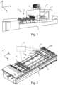
- Said base 1 has an elongated shape, whose main dimension extends mainly according to a direction of development parallel to the first axis n X.
- Said working plane 2 is coupled to said base 1 and also has an elongated shape, whose main dimension extends mainly according to a direction of development parallel to that first X axis.
- Said working plane 2 comprises a plurality of supporting bars 21 a,b,...i,...n which are slidingly coupled to said base 1 through a first 22 and a second guide 23, integral to said base 1.
- Said plurality of supporting bars 21 a,b,... i... n can be operated manually, along said first 22 and second 23 guides of said base 1, according to the X axis.
- Each supporting bar 21 i of said plurality of supporting bars 21 a,b,... i... n is aligned in a direction parallel to said second Y-axis.
- Said crossbar 31 is slidingly coupled to said base 1 in a direction parallel to said first X-axis
- the machining head 32 is slidingly coupled to said crossbar 31 along a direction parallel to said second Y-axis.
- Said machining head 32 can also be movable along a direction parallel to said third Z-axis.
- Said machining head 32 can also rotate around one, two or three or more rotation axes.
- Said plurality of supporting bars 21 a,b,... i... n is suitable for supporting panels W to be machined.
- each supporting bar 21 i there is slidingly mounted a plurality of mobile devices 24 aa,bb ... ij ... nn , such as suction cups or clamps, for locking the panels W to be processed, by means of vacuum systems, during the processing of the panel W by part said machining head 32.
- mobile devices 24 aa,bb ... ij ... nn such as suction cups or clamps, for locking the panels W to be processed, by means of vacuum systems, during the processing of the panel W by part said machining head 32.
- Said plurality of mobile devices 24 aa,bb,... ij... nn can be operated manually, along the respective bars of said plurality of supporting bars 21 a, b,...j,...n according to the Y axis.
- Each supporting bar 21 i and each mobile device 24 ij comprise means of feedback to provide the operator with information on their correct movement.
- Said means of feedback may be means for displaying, to provide visual information to the operator.
- Said means of feedback for the operator can also be acoustic or tactile, such as a vibrating means.
- Said visual means, acoustic or tactile receive the signals sent by said logical control unit U and provide visual, acoustic or tactile feedback to the operator.
- Each supporting bar 21 i and each mobile devices 24 ij comprise at least one sensor, not shown in the figure, capable of detecting respectively the position in the working plane 2 and the position along the supporting bar 21 i .
- each supporting bar 21 i and each mobile device 24 ij comprise a wireless reception and transmission module for exchanging data with said control logic unit U.
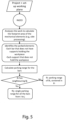
- the working plane 2 is discretized, or divided into squares or cells, then it is verified, for each cell, the potential collision between said machining head 32 during the intended processing and the mobile devices 21 a,b,...i,...n ; 24 aa,bb,...ij,...nn that are not involved in the machining program, thus obtaining a collision matrix of the working plane M ij 0 , in which each "discrete" point or cell is indexed with a row index i and a column index j , as shown in figure 3a .
- each cell ij of said M ij 0 matrix represents a real space of the square X-Y plane with sides of 1 mm.
- different measures may be envisaged.
- zone Z1 will have boundary coordinates X1, X2 and Y1, Y2 along said first X and second Y axis, respectively, which correspond to cells of the collision matrix M ij 0 .
- the positioning intervals or positioning ranges R of all the supporting bars 21 a,b,...i,...n and mobile devices 24 aa,bb,..ij...nn that are not involved in the processing are calculated,, so that they occupy a safety space free from processing, and so as not to excessively alter the initial configuration of the working plane 2.
- the positioning range R of the supporting bars 21 a,b,...i...n not involved in the machining is numerically calculated from the value 0, which coincides with the meeting point of a first side of the working plane 2, parallel to said first axis X, and a second side of the working plane parallel to that second axis Y, up to the coordinate X1 of zone Z1 and from the coordinate X2 to the end of the working plane 2 or up to the next bar, also taking into account the geometric dimensions of all the components involved.
- the supporting bars involved in machining are the bars 21 2 , 21 3 e 21 4 and 21 4 and the mobile devices involved in machining are 24 22 , 24 23 , 24 24 for bar 21 2 , mobile devices 24 31 , 24 32 , 24 33 for bar 21 3 , and mobile devices 24 43 , 24 44 , 24 45 for bar 21 4 .
- the 21 1 supporting bar have a positioning range R from 0 to X1.
- the positioning range R of a supporting bar 21 i not involved in the processing and that does not have neighboring bars has as its average value the position that said bar occupied in the initial configuration, so as not to excessively alter the configuration of the working plane 2.
- the positioning range R of a supporting bar 2i not involved in the processing which has neighboring bars not involved in the processing has instead a determined value, so as not to invade the space of the neighboring bars.
- the positioning range R of bar 21 5 will have a positioning range R from X2 up to the X-axis coordinate occupied by bar 21 6 .
- the positioning range R is calculated for each bar.
- the supports can occupy any position, conveniently the position of the initial configuration, for the bars involved in the processing, the supports not involved in the processing can occupy the space from the beginning of the bar to the first ordered Y1 of zone Z 1 and from the second ordered Y2 of zone Z 1 to the end of the bar.
- mobile device 244 6 can be moved to P" ij space, and suction cups 24 41 and 24 42 can be moved to P' ij space
- the positioning range R is calculated from the second coordinate X2 of zone Z 1 to the end of working plane 2, or, if there is a nearby parking area, the positioning ranges R are added together.
- the method for determining the position of mobile devices in a working plane and the related work center allow to change the initial configuration of the working plane quickly and safely, positioning all mobile devices in specific positions.
Applications Claiming Priority (1)
| Application Number | Priority Date | Filing Date | Title |
|---|---|---|---|
| IT102022000009287A IT202200009287A1 (it) | 2022-05-06 | 2022-05-06 | Metodo per la determinazione del posizionamento di dispositivi mobili in un piano di lavoro e centro di lavoro che implementa tale metodo. |
Publications (1)
| Publication Number | Publication Date |
|---|---|
| EP4273642A1 true EP4273642A1 (fr) | 2023-11-08 |
Family
ID=82780837
Family Applications (1)
| Application Number | Title | Priority Date | Filing Date |
|---|---|---|---|
| EP23170589.8A Pending EP4273642A1 (fr) | 2022-05-06 | 2023-04-28 | Procédé de détermination de la position des dispositifs mobiles dans un plan de travail et centre d'usinage mettant en oeuvre un tel procédé |
Country Status (2)
| Country | Link |
|---|---|
| EP (1) | EP4273642A1 (fr) |
| IT (1) | IT202200009287A1 (fr) |
Citations (5)
| Publication number | Priority date | Publication date | Assignee | Title |
|---|---|---|---|---|
| EP0507033B1 (fr) * | 1991-04-05 | 1995-02-01 | Manuel Torres Martinez | Installation de machine outil pour fixer et usiner |
| EP1872919A1 (fr) * | 2006-06-26 | 2008-01-02 | SCM GROUP S.p.A. | Centre d'usinage pour panneaux d'usinage en bois ou similaire |
| JP2015073977A (ja) * | 2013-10-11 | 2015-04-20 | 平田機工株式会社 | 処理システム |
| DE202018100790U1 (de) * | 2017-08-08 | 2018-03-20 | Rierge, S.A. | Maschine zur numerisch gesteuerten Bearbeitung von Platten aus Holz, Kunststoff und ähnlichen Materialien, der Art, die ein "Nesting"- Arbeitssystem verwenden kann |
| EP3658345B1 (fr) * | 2017-07-26 | 2021-07-07 | Biesse S.p.A. | Appareil contôlé éléctroniquement pour la coupe et l'usinage de dalles en pierres naturelles ou synthétiques ou de dalles en verre |
-
2022
- 2022-05-06 IT IT102022000009287A patent/IT202200009287A1/it unknown
-
2023
- 2023-04-28 EP EP23170589.8A patent/EP4273642A1/fr active Pending
Patent Citations (5)
| Publication number | Priority date | Publication date | Assignee | Title |
|---|---|---|---|---|
| EP0507033B1 (fr) * | 1991-04-05 | 1995-02-01 | Manuel Torres Martinez | Installation de machine outil pour fixer et usiner |
| EP1872919A1 (fr) * | 2006-06-26 | 2008-01-02 | SCM GROUP S.p.A. | Centre d'usinage pour panneaux d'usinage en bois ou similaire |
| JP2015073977A (ja) * | 2013-10-11 | 2015-04-20 | 平田機工株式会社 | 処理システム |
| EP3658345B1 (fr) * | 2017-07-26 | 2021-07-07 | Biesse S.p.A. | Appareil contôlé éléctroniquement pour la coupe et l'usinage de dalles en pierres naturelles ou synthétiques ou de dalles en verre |
| DE202018100790U1 (de) * | 2017-08-08 | 2018-03-20 | Rierge, S.A. | Maschine zur numerisch gesteuerten Bearbeitung von Platten aus Holz, Kunststoff und ähnlichen Materialien, der Art, die ein "Nesting"- Arbeitssystem verwenden kann |
Also Published As
| Publication number | Publication date |
|---|---|
| IT202200009287A1 (it) | 2023-11-06 |
Similar Documents
| Publication | Publication Date | Title |
|---|---|---|
| EP2846206B1 (fr) | Dispositif et procédé pour régler automatiquement la valeur de décalage d'outil d'une machine-outil | |
| US10228686B2 (en) | Robot programming device for teaching robot program | |
| US20110295408A1 (en) | Process for positioning a workpiece | |
| EP2584419A2 (fr) | Machine CNC de découpe par plasma, oxygène et jet d'eau utilisés comme outil de coupe avec réglage automatique de position précise d'un outil de coupe dans une tête de coupe par auto-étalonnage et procédé associé | |
| US11703828B2 (en) | System and method for automated precision control of a computer numerical control (CNC) machine | |
| EP4273642A1 (fr) | Procédé de détermination de la position des dispositifs mobiles dans un plan de travail et centre d'usinage mettant en oeuvre un tel procédé | |
| US6480757B1 (en) | Method of locating a workpiece on a computer numeric controlled machining system | |
| EP0957417B1 (fr) | Procédé et dispositif pour mesurer la forme d'un objet et machine de mesure de coordonnées | |
| SE459717B (sv) | Plaatbearbetningsmaskin och ett medelst maskinen genomfoerbart foerfarande | |
| JP3464307B2 (ja) | Nc旋盤における干渉チェック方法 | |
| US20020165637A1 (en) | Method for highly automated manufacture of metal parts | |
| KR101751756B1 (ko) | Cnc 방전가공기의 전극 세팅 방법 | |
| KR20070068797A (ko) | 프로펠러의 자동화 가공방법 | |
| EP4273641A1 (fr) | Procédé de détermination de tolerances pour placer de dispositifs d'accouplement et centre d'usinage pour la mise en oeuvre d'un tel procédé | |
| KR102504724B1 (ko) | 터닝 센터 | |
| KR101393090B1 (ko) | 머시닝센터 가공을 위한 공작물 세팅방법 | |
| CN109732399B (zh) | 一种数控机床的对刀方法、装置、电子设备和存储介质 | |
| KR20120103993A (ko) | 세팅된 공구의 안전영역 판단 방법 및 판단 장치 | |
| JP2007249671A (ja) | 工作機械の衝突防止方法 | |
| JP4549150B2 (ja) | 工作機械の干渉領域設定方法 | |
| CN100537145C (zh) | 用于机床控制的装置和方法 | |
| KR101577572B1 (ko) | 공작물 원점 자동 설정 방법, 장치 및 이를 포함하는 머시닝 센터 | |
| KR101507683B1 (ko) | 스마트 수치제어 시스템 및 그 방법 | |
| US20060074511A1 (en) | Calibration method of an erosion machine and a grinding machine | |
| TWI813128B (zh) | 電極治具的中心校正方法 |
Legal Events
| Date | Code | Title | Description |
|---|---|---|---|
| PUAI | Public reference made under article 153(3) epc to a published international application that has entered the european phase |
Free format text: ORIGINAL CODE: 0009012 |
|
| STAA | Information on the status of an ep patent application or granted ep patent |
Free format text: STATUS: THE APPLICATION HAS BEEN PUBLISHED |
|
| AK | Designated contracting states |
Kind code of ref document: A1 Designated state(s): AL AT BE BG CH CY CZ DE DK EE ES FI FR GB GR HR HU IE IS IT LI LT LU LV MC ME MK MT NL NO PL PT RO RS SE SI SK SM TR |
|
| STAA | Information on the status of an ep patent application or granted ep patent |
Free format text: STATUS: REQUEST FOR EXAMINATION WAS MADE |
|
| 17P | Request for examination filed |
Effective date: 20240321 |
|
| RBV | Designated contracting states (corrected) |
Designated state(s): AL AT BE BG CH CY CZ DE DK EE ES FI FR GB GR HR HU IE IS IT LI LT LU LV MC ME MK MT NL NO PL PT RO RS SE SI SK SM TR |