EP4273440B1 - Lichtmodul mit mehreren vorsatzoptiken - Google Patents
Lichtmodul mit mehreren vorsatzoptiken Download PDFInfo
- Publication number
- EP4273440B1 EP4273440B1 EP23169615.4A EP23169615A EP4273440B1 EP 4273440 B1 EP4273440 B1 EP 4273440B1 EP 23169615 A EP23169615 A EP 23169615A EP 4273440 B1 EP4273440 B1 EP 4273440B1
- Authority
- EP
- European Patent Office
- Prior art keywords
- light
- preliminary
- subsection
- optics
- partial
- Prior art date
- Legal status (The legal status is an assumption and is not a legal conclusion. Google has not performed a legal analysis and makes no representation as to the accuracy of the status listed.)
- Active
Links
Images




Classifications
-
- F—MECHANICAL ENGINEERING; LIGHTING; HEATING; WEAPONS; BLASTING
- F21—LIGHTING
- F21S—NON-PORTABLE LIGHTING DEVICES; SYSTEMS THEREOF; VEHICLE LIGHTING DEVICES SPECIALLY ADAPTED FOR VEHICLE EXTERIORS
- F21S41/00—Illuminating devices specially adapted for vehicle exteriors, e.g. headlamps
- F21S41/20—Illuminating devices specially adapted for vehicle exteriors, e.g. headlamps characterised by refractors, transparent cover plates, light guides or filters
- F21S41/25—Projection lenses
- F21S41/275—Lens surfaces, e.g. coatings or surface structures
-
- F—MECHANICAL ENGINEERING; LIGHTING; HEATING; WEAPONS; BLASTING
- F21—LIGHTING
- F21S—NON-PORTABLE LIGHTING DEVICES; SYSTEMS THEREOF; VEHICLE LIGHTING DEVICES SPECIALLY ADAPTED FOR VEHICLE EXTERIORS
- F21S41/00—Illuminating devices specially adapted for vehicle exteriors, e.g. headlamps
- F21S41/10—Illuminating devices specially adapted for vehicle exteriors, e.g. headlamps characterised by the light source
- F21S41/14—Illuminating devices specially adapted for vehicle exteriors, e.g. headlamps characterised by the light source characterised by the type of light source
- F21S41/141—Light emitting diodes [LED]
- F21S41/147—Light emitting diodes [LED] the main emission direction of the LED being angled to the optical axis of the illuminating device
-
- F—MECHANICAL ENGINEERING; LIGHTING; HEATING; WEAPONS; BLASTING
- F21—LIGHTING
- F21S—NON-PORTABLE LIGHTING DEVICES; SYSTEMS THEREOF; VEHICLE LIGHTING DEVICES SPECIALLY ADAPTED FOR VEHICLE EXTERIORS
- F21S41/00—Illuminating devices specially adapted for vehicle exteriors, e.g. headlamps
- F21S41/10—Illuminating devices specially adapted for vehicle exteriors, e.g. headlamps characterised by the light source
- F21S41/14—Illuminating devices specially adapted for vehicle exteriors, e.g. headlamps characterised by the light source characterised by the type of light source
- F21S41/141—Light emitting diodes [LED]
- F21S41/151—Light emitting diodes [LED] arranged in one or more lines
-
- F—MECHANICAL ENGINEERING; LIGHTING; HEATING; WEAPONS; BLASTING
- F21—LIGHTING
- F21S—NON-PORTABLE LIGHTING DEVICES; SYSTEMS THEREOF; VEHICLE LIGHTING DEVICES SPECIALLY ADAPTED FOR VEHICLE EXTERIORS
- F21S41/00—Illuminating devices specially adapted for vehicle exteriors, e.g. headlamps
- F21S41/20—Illuminating devices specially adapted for vehicle exteriors, e.g. headlamps characterised by refractors, transparent cover plates, light guides or filters
- F21S41/25—Projection lenses
-
- F—MECHANICAL ENGINEERING; LIGHTING; HEATING; WEAPONS; BLASTING
- F21—LIGHTING
- F21S—NON-PORTABLE LIGHTING DEVICES; SYSTEMS THEREOF; VEHICLE LIGHTING DEVICES SPECIALLY ADAPTED FOR VEHICLE EXTERIORS
- F21S41/00—Illuminating devices specially adapted for vehicle exteriors, e.g. headlamps
- F21S41/20—Illuminating devices specially adapted for vehicle exteriors, e.g. headlamps characterised by refractors, transparent cover plates, light guides or filters
- F21S41/25—Projection lenses
- F21S41/265—Composite lenses; Lenses with a patch-like shape
-
- F—MECHANICAL ENGINEERING; LIGHTING; HEATING; WEAPONS; BLASTING
- F21—LIGHTING
- F21S—NON-PORTABLE LIGHTING DEVICES; SYSTEMS THEREOF; VEHICLE LIGHTING DEVICES SPECIALLY ADAPTED FOR VEHICLE EXTERIORS
- F21S41/00—Illuminating devices specially adapted for vehicle exteriors, e.g. headlamps
- F21S41/20—Illuminating devices specially adapted for vehicle exteriors, e.g. headlamps characterised by refractors, transparent cover plates, light guides or filters
- F21S41/25—Projection lenses
- F21S41/27—Thick lenses
-
- F—MECHANICAL ENGINEERING; LIGHTING; HEATING; WEAPONS; BLASTING
- F21—LIGHTING
- F21S—NON-PORTABLE LIGHTING DEVICES; SYSTEMS THEREOF; VEHICLE LIGHTING DEVICES SPECIALLY ADAPTED FOR VEHICLE EXTERIORS
- F21S41/00—Illuminating devices specially adapted for vehicle exteriors, e.g. headlamps
- F21S41/30—Illuminating devices specially adapted for vehicle exteriors, e.g. headlamps characterised by reflectors
- F21S41/32—Optical layout thereof
- F21S41/322—Optical layout thereof the reflector using total internal reflection
-
- F—MECHANICAL ENGINEERING; LIGHTING; HEATING; WEAPONS; BLASTING
- F21—LIGHTING
- F21S—NON-PORTABLE LIGHTING DEVICES; SYSTEMS THEREOF; VEHICLE LIGHTING DEVICES SPECIALLY ADAPTED FOR VEHICLE EXTERIORS
- F21S41/00—Illuminating devices specially adapted for vehicle exteriors, e.g. headlamps
- F21S41/30—Illuminating devices specially adapted for vehicle exteriors, e.g. headlamps characterised by reflectors
- F21S41/32—Optical layout thereof
- F21S41/323—Optical layout thereof the reflector having two perpendicular cross sections having regular geometrical curves of a distinct nature
-
- F—MECHANICAL ENGINEERING; LIGHTING; HEATING; WEAPONS; BLASTING
- F21—LIGHTING
- F21S—NON-PORTABLE LIGHTING DEVICES; SYSTEMS THEREOF; VEHICLE LIGHTING DEVICES SPECIALLY ADAPTED FOR VEHICLE EXTERIORS
- F21S41/00—Illuminating devices specially adapted for vehicle exteriors, e.g. headlamps
- F21S41/30—Illuminating devices specially adapted for vehicle exteriors, e.g. headlamps characterised by reflectors
- F21S41/32—Optical layout thereof
- F21S41/36—Combinations of two or more separate reflectors
- F21S41/365—Combinations of two or more separate reflectors successively reflecting the light
-
- F—MECHANICAL ENGINEERING; LIGHTING; HEATING; WEAPONS; BLASTING
- F21—LIGHTING
- F21V—FUNCTIONAL FEATURES OR DETAILS OF LIGHTING DEVICES OR SYSTEMS THEREOF; STRUCTURAL COMBINATIONS OF LIGHTING DEVICES WITH OTHER ARTICLES, NOT OTHERWISE PROVIDED FOR
- F21V13/00—Producing particular characteristics or distribution of the light emitted by means of a combination of elements specified in two or more of main groups F21V1/00 - F21V11/00
- F21V13/02—Combinations of only two kinds of elements
- F21V13/04—Combinations of only two kinds of elements the elements being reflectors and refractors
-
- F—MECHANICAL ENGINEERING; LIGHTING; HEATING; WEAPONS; BLASTING
- F21—LIGHTING
- F21V—FUNCTIONAL FEATURES OR DETAILS OF LIGHTING DEVICES OR SYSTEMS THEREOF; STRUCTURAL COMBINATIONS OF LIGHTING DEVICES WITH OTHER ARTICLES, NOT OTHERWISE PROVIDED FOR
- F21V5/00—Refractors for light sources
- F21V5/04—Refractors for light sources of lens shape
-
- F—MECHANICAL ENGINEERING; LIGHTING; HEATING; WEAPONS; BLASTING
- F21—LIGHTING
- F21V—FUNCTIONAL FEATURES OR DETAILS OF LIGHTING DEVICES OR SYSTEMS THEREOF; STRUCTURAL COMBINATIONS OF LIGHTING DEVICES WITH OTHER ARTICLES, NOT OTHERWISE PROVIDED FOR
- F21V7/00—Reflectors for light sources
- F21V7/04—Optical design
-
- F—MECHANICAL ENGINEERING; LIGHTING; HEATING; WEAPONS; BLASTING
- F21—LIGHTING
- F21W—INDEXING SCHEME ASSOCIATED WITH SUBCLASSES F21K, F21L, F21S and F21V, RELATING TO USES OR APPLICATIONS OF LIGHTING DEVICES OR SYSTEMS
- F21W2102/00—Exterior vehicle lighting devices for illuminating purposes
-
- F—MECHANICAL ENGINEERING; LIGHTING; HEATING; WEAPONS; BLASTING
- F21—LIGHTING
- F21W—INDEXING SCHEME ASSOCIATED WITH SUBCLASSES F21K, F21L, F21S and F21V, RELATING TO USES OR APPLICATIONS OF LIGHTING DEVICES OR SYSTEMS
- F21W2107/00—Use or application of lighting devices on or in particular types of vehicles
- F21W2107/10—Use or application of lighting devices on or in particular types of vehicles for land vehicles
Definitions
- the invention relates to a light module for a motor vehicle headlight according to the preamble of claim 1.
- the light module comprises at least two semiconductor light sources, each with an auxiliary optic assigned to a respective semiconductor light source.
- the auxiliary optics are connected to one another in the form of a primary optics unit and are arranged next to one another with respect to a horizontal extension of the primary optics unit.
- Such a light module is known, for example, from the DE 10 2013 207 850 A1 .
- Each attachment optic comprises a light entry area with a central light entry area and a peripheral light entry area, and a light deflection area adjoining the peripheral light entry area.
- a light module according to the preamble of claim 1 is known.
- the upper and lower light deflection surfaces are asymmetry.
- the light modules known from the prior art have the disadvantage that the primary optics require a relatively large installation depth and, on the other hand, they include sharp-edged separations, in particular between the light exit surfaces of the individual attachment optics, and are therefore difficult to implement in terms of tool technology.
- the present invention is based on the object of overcoming the disadvantages known from the prior art.
- the light deflection region of a respective attachment optics comprises a first partial region and a second partial region, wherein the first partial region is arranged closer to a center of the primary optics unit with respect to the horizontal extension of the primary optics unit along a horizontal axis than the second partial region and the second partial region is arranged closer to an outer side of the primary optics unit with respect to the horizontal extension of the primary optics unit than the first partial region, wherein a curvature and/or an inclination of the first partial region starting from the peripheral light entry region is flatter than a curvature and/or an inclination of the second partial region, and the curvature and/or the inclination of the second partial region starting from the peripheral light entry region is steeper than the curvature and/or the inclination of the first partial region, so that a direction of a first optical axis of the first partial region differs from a direction of a second optical axis of the second partial region.
- Light rays that are deflected at the first partial area of the light deflection area of a respective attachment optic are deflected in a different direction than light rays that are deflected at the second partial area of the light deflection area of a respective attachment optic.
- the deflection of the light in directions deviating from a main beam direction of the light module is achieved via the described design of the light deflection area.
- the deflection no longer has to be carried out using the light exit surfaces of the additional optics and no strong tilting or pronounced inclination of the light exit surfaces of the additional optics is required.
- the primary optics can be designed to be flatter overall.
- the deflection area of the additional optics is rotationally symmetrical, and thus no average deflection of the light from the optical axis of the light source occurs due to the deflection area.
- this requires a greater installation depth.
- the different curvature and/or inclination of the two sub-regions provides that the surface of the first sub-region, which is closer to the center of the primary optics unit, is flatter in relation to the peripheral light entry region, i.e. a larger angle is formed between the peripheral light entry region and the surface of the first sub-region compared to the second sub-region. Accordingly, it is provided that the surface of the second sub-region, which is closer to the outside of the primary optics unit, is steeper in relation to the peripheral light entry region, i.e. a smaller angle is formed between the peripheral light entry region and the surface of the second sub-region compared to the first sub-region.
- the light entry area with the central and peripheral light entry area is, for example, rotationally symmetrical.
- the light deflection area adjacent to the peripheral light entry area is not rotationally symmetrical due to the variation in the inclination and/or curvature of the surface forming the light deflection area.
- the attachment optics can therefore also be referred to as attachment optics with asymmetrical light deflection areas.
- a low beam distribution or a partial light distribution of a low beam distribution is generated with the light module, and that light rays which are deflected at the first partial areas of the attachment optics illuminate a central area of the low beam distribution on a measuring screen arranged in front of the light module at a distance from it in the area around an intersection point of a horizontal and a vertical.
- the light rays deflected at the first partial area thus illuminate a central area of the low beam distribution.
- the central area lies on the measuring screen in a horizontal direction in a range of up to +/- 15°.
- the low beam distribution has a substantially horizontally running light-dark boundary which limits the light distribution upwards and for example, along the horizontal or just below or above the horizontal, e.g. at -/+ 1°.
- the central area on the measuring screen is approximately in a range of - 10°, in particular - 7°, to the light-dark border.
- the light-dark border is preferably designed as an asymmetrical light-dark border, i.e. it has a section on the own side of the traffic that is higher than a section on the oncoming traffic side in order to reduce dazzling of oncoming road users.
- the transition between the sections of the light-dark border on the own side of the traffic and the oncoming traffic side can be designed as desired, e.g. diagonally rising or stepped.
- a single first sub-area, in particular a respective first sub-area of a single optical attachment, in particular a respective optical attachment, could completely illuminate the central area of the low beam distribution.
- the first sub-areas each illuminate a part of the central area and the illumination of the entire central area of the low beam distribution results from superimposing the illuminated parts of the central area.
- light rays which are deflected at the second partial regions of the attachment optics illuminate a wide region of the low beam distribution in the horizontal direction, wherein the wide region is wider in the horizontal direction than the central region illuminated by the first partial regions.
- the second areas of the attachment optics ensure a particularly wide basic light distribution of the low beam distribution.
- the wide area of the low beam distribution extends horizontally, for example, in a range of up to -/+ 45°, in particular +/- 35°. In the vertical direction, the wide area on the measuring screen is approximately in a range of - 15°, in particular - 12°, up to the light-dark boundary.
- a single second sub-area in particular a respective second sub-area of a single optical attachment, in particular a respective optical attachment, could completely illuminate the wide area of the low beam distribution.
- the second sub-areas each illuminate a part of the wide area and the illumination of the entire wide area of the low beam distribution results from superimposing the illuminated parts of the wide area.
- the first and second sub-areas of a respective attachment optics merge continuously into one another.
- the light deflection area of the attachment optics therefore has no steps or edges. This is advantageous on the one hand because no steps or edges are shown in the light distribution. Light deflected in the light deflection area can thus contribute homogeneously to the light distribution.
- the attachment optics and thus the primary optics can thus be made very flat in the direction of the optical axes. On the other hand, demoldability is improved when producing the primary optics, for example in an injection molding process.
- a respective light deflection region of a respective attachment optics is divided into the first and the second partial region along a vertical plane perpendicular to the horizontal axis or along an inclined plane oblique to the horizontal axis.
- the primary optics comprises an auxiliary optics arranged centrally between the at least two further auxiliary optics, wherein the centrally arranged auxiliary optics comprises a symmetrical, in particular rotationally symmetrical or axially symmetrical, light deflection region.
- the primary optics accordingly comprise between three and nine, in particular between five and seven, auxiliary optics assigned to a respective semiconductor light source.
- the semiconductor light sources and the auxiliary optics jointly generate the low beam distribution, in particular by superimposing the areas illuminated by a respective semiconductor light source and a respective attachment optics.
- the primary optics comprises a light exit surface and that light exit surface areas assigned to a respective front optics merge continuously into one another.
- the primary optics therefore comprises a continuous light exit surface.
- the light exit surface of the primary optics therefore has no steps or edges. This is advantageous on the one hand because no steps or edges are depicted in the light distribution.
- the demoldability is improved when producing the primary optics, for example in an injection molding process.
- a further arrangement of at least two auxiliary optics arranged next to one another is provided above or below the at least two auxiliary optics.
- the primary optics can therefore comprise a type of two-row arrangement of at least two auxiliary optics each. It can also be provided that two separate primary optics are formed, each comprising at least two auxiliary optics arranged next to one another.
- At least one semiconductor light source is assigned to each of the at least two auxiliary optics of the further arrangement arranged next to one another.
- the further arrangement generates a high beam distribution or a partial light distribution of a high beam distribution.
- the further arrangement can generate a partial light distribution that supplements the low beam distribution by a further area above the horizontal to form a high beam distribution.
- the design of the auxiliary optics for generating the high beam distribution can advantageously be carried out analogously to the auxiliary optics for generating the low beam distribution, with the proviso that partial areas of light deflection areas are designed such that light deflected at the partial areas is deflected into corresponding areas of the partial light distribution.
- a diaphragm arrangement in particular comprising a mirror diaphragm
- the diaphragm arrangement serves to form the light-dark boundary and is arranged in the beam path of the light module. It is also preferred that one side of the diaphragm arrangement or both sides of the diaphragm arrangement are designed as reflective surfaces.
- the light module comprises a secondary optic, in particular a projection lens.
- a secondary optic By means of the secondary optic, light is projected in the light exit direction onto the road in front of the motor vehicle.
- FIG. 1 shows a motor vehicle headlight designated in its entirety by the reference number 10.
- the motor vehicle headlight 10 comprises a housing 12 which is preferably made of plastic. In a light exit direction 14, the housing 12 has a light exit opening 16 which is closed by a transparent cover plate 18.
- the cover plate 18 is made of colorless plastic or glass.
- the plate 18 can be designed as a so-called clear plate without optically effective profiles. Alternatively, the plate 18 can be provided at least in some areas with optically effective profiles (e.g. cylindrical lenses or prisms) which cause the light passing through to be scattered, preferably in a horizontal direction.
- the headlight 10 is intended for installation on an attachment side of a motor vehicle. Two of the headlights 10 shown, which are arranged on different attachment sides of the motor vehicle, form a motor vehicle lighting device according to the invention.
- the headlights 10 installed on different attachment sides are preferably mirror-symmetrical to one another with regard to their general geometric external appearance.
- a light module 20 is arranged inside the headlight housing 12.
- the light module 20 generates at least a light distribution that meets legal and regulatory requirements.
- the light module 20 is designed as a light module according to the invention.
- the light module 20 is described below with reference to the Figures 2 to 9 explained in detail.
- the light module 20 comprises at least two semiconductor light sources 22 arranged next to one another. Fig. 2 In section, only one semiconductor light source 22 can be seen.
- the light module 20 further comprises at least one primary optics unit 24.
- the primary optics unit 24 comprises at least two auxiliary optics 26, each associated with a respective semiconductor light source 22.
- Figure 3 shows an exemplary representation of the primary optics unit 24.
- the primary optics unit 24 comprises, for example, seven auxiliary optics 26, which are arranged in accordance with Fig. 3 are provided with the reference numerals 26-1 to 26-7.
- the primary optics unit 24 comprises at least two, or between three and nine, in particular between five and seven, light sources 22 arranged next to one another and accordingly at least two, or between three and nine, in particular between five and seven, auxiliary optics 26 assigned to a respective semiconductor light source 22.
- auxiliary optics 26 are arranged next to one another in or opposite to the y-direction with respect to a horizontal extension 28 of the primary optics unit 24.
- a respective attachment optics 26 comprises a light entry area 30 with a central light entry area 32 and a peripheral light entry area 34.
- the light entry area 30 is in Fig. 3 not shown for all attachment optics.
- the light entry areas 30 can be identical for all attachment optics 26.
- the light entry region 30 is rotationally symmetrical.
- the central light entry area 32 is designed as a lens, for example.
- the peripheral light entry area 34 widens slightly from the central area 32, for example in a funnel shape.
- a light deflection area 36 adjoins the peripheral light entry area 34.
- the light deflection region 36 is not rotationally symmetrical.
- the auxiliary optics 26-1, 26-2, 26-3 and 26-5, 26-6, 26-7 can therefore also be referred to as auxiliary optics with asymmetrical light deflection regions 36.
- the asymmetrical light deflection area 36 is first described by way of example using the attachment optics 26-6 with reference to the Figures 4a to 4c However, the explanations apply analogously to the attachment optics 26-5 and 26-7.
- Fig. 4a shows the auxiliary optics 26-6 as a section of the primary optics 24.
- the light deflection region 36 of the auxiliary optics 26-6 comprises a first partial region 38, cf. Fig. 4b , and a second sub-area 40, cf. Fig. 4c .
- the first partial area 38 is arranged closer to a center 42 of the primary optics unit 24 with respect to the horizontal extension of the primary optics unit 24 along the horizontal axis 28 than the second partial area 40.
- a center 42 is shown by way of example in Fig. 3 drawn in. The center does not necessarily have to be a point arranged exactly in the middle.
- a center in the context of the present invention is understood to be a point in the region of a middle, in particular in relation to the horizontal extent, of the primary optics unit 24.
- the second partial area 40 is arranged closer to an outer side 44 of the primary optics unit 24 in relation to the horizontal extent of the primary optics unit 24 than the first partial area 38.
- a curvature and/or an inclination of the first partial area 38 starting from the peripheral light entry area 34 is flatter than a curvature and/or an inclination of the second partial area 40.
- the curvature and/or the inclination of the second partial area 40 starting from the peripheral light entry area 34 is steeper than the curvature and/or the inclination of the first partial area 38.
- the light deflection area 36 includes curved surfaces.
- the light deflection area 36 can also include flat, inclined surfaces.
- the first partial region 38 comprises a first optical axis 46.
- the second partial region comprises a second optical axis 48. Due to the variation of the curvature and/or the inclination of the two partial regions 38, 40, a direction of the first optical axis 46 of the first partial region 38 differs from the direction of the second optical axis 48 of the second partial region 40.
- the deflection of the light in directions deviating from a main radiation direction of the light module 20 is achieved via the described design of the light deflection region 36.
- the light module 20 can, for example, be used to create a low beam distribution 50, cf. Fig. 6 , are generated.
- the low beam distribution 50 has a substantially horizontally extending light-dark boundary 52, which limits the light distribution upwards and runs, for example, along the horizontal or just above or below the horizontal, e.g. at +/-1°.
- the light-dark boundary 52 is preferably designed as an asymmetrical light-dark boundary 52, i.e. it has a section on the own side of the traffic with a higher profile than a section on the oncoming traffic side in order to reduce dazzling of oncoming road users.
- the transition between the sections of the light-dark boundary 52 on the own side of the traffic and the oncoming traffic side can be designed as desired, e.g. diagonally rising or stepped.
- an aperture arrangement 54 is used, cf. Fig. 2 , for example a mirror aperture is provided.
- the aperture arrangement 54 is arranged in the beam path of the light module 20.
- At least one upper side 56 of the aperture arrangement 54 is designed, for example, as a reflective surface.
- the aperture 54 is arranged with respect to a secondary optics 58, for example a projection lens, such that an edge 60 of the aperture arrangement 54 is imaged by the secondary optics 58 as a light-dark boundary in the low beam distribution 50.
- a secondary optics 58 for example a projection lens
- the low beam distribution 50 in Fig. 6 is generated using the primary optics 24.
- the low beam distribution 50 is generated by superimposing individual partial light distributions of the respective auxiliary optics 26.
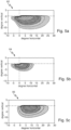
- Fig. 5a shows, for example, a partial light distribution 62 of the low beam distribution 50 which is generated with the attachment optics 26-6.
- Light rays that are deflected at the two partial areas 38, 40 of the attachment optics 26-6 are directed in different directions due to the different optical axes 46, 48 of the two partial areas 38, 40 and therefore illuminate different areas of the low beam distribution 50 or the partial light distribution 62 of the low beam distribution 50.
- Light rays which are deflected at the first partial region 38 of the attachment optics 26-6 illuminate a central region 64 of the low beam distribution 50 or the partial light distribution 62 or a part thereof on a measuring screen arranged in front of the light module 20 at a distance therefrom in the region around an intersection point of a horizontal H and a vertical V.
- the central area 64 on the measuring screen lies, for example, in a horizontal direction in a range of up to +/- 15°. In the vertical direction, the central area 64' on the measuring screen lies approximately in a range of - 10°, in particular - 7°, up to the light-dark boundary 52.
- the first partial area 38 of the auxiliary optics 26-6 illuminates a part 64 of the central area 64', cf. Fig. 5b
- the first partial area 38 illuminates an area between - 12° and + 7° horizontally and between - 7° to the light-dark boundary 52.
- First partial areas 38 of the further attachment optics for example 26-1, 26-2, 26-3, 26-5, 26-7, each illuminate a further part 64 of the central area 64' in an offset manner.
- the illumination of the entire central area 64' of the low beam distribution 50, Fig. 6 is obtained, for example, by superimposing the parts 64 of the central region 64' illuminated by the first partial regions of the auxiliary optics 26 of the primary optics 24.
- the light beams deflected in partial areas 38 thus illuminate a central area 64' of the low beam distribution 50.
- Light rays that are deflected at the second partial area 40 of the front optics 26-6 illuminate a wide area 66 of the low beam distribution 50 or the partial light distribution 62 or a part thereof in the horizontal direction on a measuring screen arranged in front of the light module 20 at a distance from it.
- the wide area 66 is wider in the horizontal direction than the central area 64 illuminated by the first partial areas 38.
- the wide area 66' of the low beam distribution 50 extends in the horizontal direction, for example, in a range of up to -/+ 45°, in particular +/- 35°.
- the wide area 66' on the measuring screen lies approximately in a range of - 15°, in particular - 12°, up to the light-dark boundary 52.
- the second partial area 40 of the attachment optics 26-6 illuminates a part 66 of the wide area 66', cf. Fig. 5c
- the second partial area 40 illuminates an area between - 2° and + 25° horizontally and between - 11° to the light-dark boundary 52.
- Further second partial areas 40 of the further attachment optics for example 26-1, 26-2, 26-3, 26-5, 26-7, each illuminate a further part 66 of the wide area 66' in an offset manner.
- the illumination of the entire wide area 66' of the low beam distribution 50, Fig. 6 results, for example, from superimposing the parts 66 of the wide area 66' illuminated by the second partial areas of the auxiliary optics 26 of the primary optics 24.
- the second areas 40 of the auxiliary optics 26 thus ensure a particularly wide basic light distribution of the low beam distribution 50.
- the inclination and/or curvature of the first and second partial regions 38, 40 of the additional optics 26-1, 26-2, 26-3, 26-5, 26-6, 26-7 can vary.
- the difference in the inclination and/or curvature of the first and second partial regions 38, 40 is greatest in the outer additional optics 26-1 and 26-7 and the difference decreases inwards up to the additional optics 26-3 and 26-5.
- the front optics 26-1, 26-2, 26-3 are mirrored to the representations in the Figures 5a to 5c formed, ie the first partial area 38 is arranged on the right side and the second partial area 40 is arranged on the left side.
- the light deflection area 36' of the auxiliary optics 26-4 which is arranged in the middle of the auxiliary optics 26, is rotationally symmetrical. This does not necessarily have to be the case, but can prove advantageous for reasons of symmetry.
- the auxiliary optics 26-4 is accordingly an auxiliary optics with a symmetrical light deflection area 36'.
- the light deflection area 36' of the auxiliary optics 26-4 illuminates the central area 52 or part of the central area 52 of the low beam distribution 50.
- Fig. 7 shows a further embodiment of the light module 20 according to the invention.
- the primary optics 24 of the light module is made of Fig. 2 supplemented by a further arrangement 68 of auxiliary optics 70.
- a further arrangement 68 of at least two auxiliary optics 70 arranged next to one another is provided below the auxiliary optics 26.
- At least one semiconductor light source 72 is assigned to each of the auxiliary optics 70 of the further arrangement 68.
- an underside 56' of the diaphragm arrangement 54 is designed as a reflective surface.
- the primary optics 24 can therefore comprise a kind of two-row arrangement of the auxiliary optics 26 and the auxiliary optics 70, cf. Figures 8a to 8c However, it can also be provided that two separate primary optics (not shown) are formed.
- the primary optics 24 comprises the auxiliary optics 26-1 to 26-7 in an upper row.
- the auxiliary optics 70-1 to 70-5 are arranged in a lower row.
- the light deflection areas 36 and the light entry areas 30 of the attachment optics 26-1 to 26-7 are visible.
- the first and second partial areas 38, 40 of the light deflection areas 36 of the attachment optics 26-1 and 26-7 are marked as examples.
- the auxiliary optics 70-1 to 70-5 can be designed according to the same principle as the auxiliary optics 26-1 to 26-7.
- the auxiliary optics 70-1 to 70-5 also comprise, for example, light entry regions 30.
- light deflection regions 74 of the auxiliary optics 70-1, 70-2 and 70-4, 70-5 also comprise a first and a second partial region 76, 78.
- the first partial region 76 is, for example, analogous to the first partial region 38, arranged closer to a center 42 of the primary optics unit 24 with respect to the horizontal extension of the primary optics unit 24 along the horizontal axis 28 than the second partial region 78.
- a curvature and/or an inclination of the first partial region 76, starting from the peripheral light entry region 34, is flatter than a curvature and/or an inclination of the second partial region 78.
- the curvature and/or the inclination of the second partial region 78, starting from the peripheral light entry region 34 is steeper than the curvature and/or the inclination of the first partial region 76.
- optical axes of the first and second partial regions 76, 78 also differ from one another in an analogous manner.
- the partial areas 76, 78 are designed such that the first partial area 76 illuminates a central area of a partial light distribution and the second partial area 78 illuminates a broad area of a partial light distribution.
- the further arrangement 68 is used, for example, to generate a partial light distribution of a high beam distribution.
- the further arrangement 68 can be used to generate a partial light distribution that supplements the low beam distribution 50 by a further area 80 above the horizontal to form a high beam distribution 82, cf. Fig. 9 .
- the first partial areas 76 of the auxiliary optics 70-1, 70-2 and 70-4, 70-5 each illuminate, for example, a part of the central area which extends on a measuring screen in a range of approximately -/+ 10° horizontally and from the light-dark boundary to + 5° vertically.
- the second partial areas 78 of the auxiliary optics 70-1, 70-2 and 70-4, 70-5 each illuminate, for example, a part of a wide area which extends on a measuring screen in a range of -/+ 22° horizontally and from the light-dark boundary to +8° vertically.
- the partial light distribution 80 results from the superposition of the parts illuminated by the first and second partial areas 76, 78 of the attachment optics 70.
- a centrally arranged front optic 70-3 comprises an axially symmetrical deflection region 84.
- the partial regions 84', 84" are formed symmetrically to a plane 86 which, in the example, runs vertically.
- the two partial areas 84', 84" of the attachment optics 70-3 illuminate the central area of the partial light distribution 80.
- the respective light deflection areas 36, 74 and 84 of a respective attachment optics 26, 70 are each divided into the first and the second sub-area along a vertical plane 88 perpendicular to the horizontal axis 28, see attachment optics 70-1 as an example.
- the division can also take place along a plane running obliquely to the horizontal axis 28.
- the plane 88 does not necessarily run through a center point of the rotationally symmetrical light entry area 30.
- the plane can also run offset along the horizontal axis 28.
- a respective light deflection area 36, 74, 84 of the attachment optics 26, 70 therefore has no steps or edges.
- the Figures 8b and 8c show the primary optics 24 in a perspective view and in a view from the front.
- the primary optics comprises an upper light exit surface 90 and a lower light exit surface 92.
- the light exit surfaces 90, 92 could also be connected to form a common light exit surface.
- the light exit surface 90 comprises light exit surface areas 90-1 to 90-7. These are each assigned to an additional optic 26-1 to 26-7.
- the light exit surface 92 comprises light exit surface areas 92-1 to 92-5. These are each assigned to an additional optic 70-1 to 70-5. It is intended that the light exit surface areas 90-1 to 90-7 and 92-1 to 92-5 merge continuously into one another.
- the primary optic 24 therefore comprises two continuous light exit surfaces 90, 92.
- the light exit surfaces 90, 92 of the primary optic 24 therefore have no steps or edges.
Landscapes
- Engineering & Computer Science (AREA)
- General Engineering & Computer Science (AREA)
- Physics & Mathematics (AREA)
- Microelectronics & Electronic Packaging (AREA)
- Optics & Photonics (AREA)
- Geometry (AREA)
- Non-Portable Lighting Devices Or Systems Thereof (AREA)
Description
- Die Erfindung betrifft ein Lichtmodul für einen Kraftfahrzeugscheinwerfer gemäß dem Oberbegriff des Anspruchs 1. Demgemäß umfasst das Lichtmodul mindestens zwei Halbleiterlichtquellen mit jeweils einer einer jeweiligen Halbleiterlichtquelle zugeordneten Vorsatzoptik. Die Vorsatzoptiken sind miteinander in Form einer Primäroptikeinheit verbunden und sind in Bezug auf eine horizontale Erstreckung der Primäroptikeinheit nebeneinander angeordnet.
- Ein solches Lichtmodul ist beispielsweise bekannt aus der
DE 10 2013 207 850 A1 . Eine jeweilige Vorsatzoptik umfasst einen Lichteintrittsbereich mit jeweils einem zentralen Lichteintrittsbereich und einen peripheren Lichteintrittsbereich, und einen an den peripheren Lichteintrittsbereich anschließenden Lichtumlenkbereich. Weiter ist aus derWO 2011/154470 A1 ein Lichtmodul gemäß dem Oberbegriff des Anspruchs 1 bekannt. Bei dem bekannten Lichtmodul weisen obere und untere Lichtumlenkflächen eine Asymmetrie auf. Die aus dem Stand der Technik bekannten Lichtmodulen weisen den Nachteil auf, dass die Primäroptiken zum einen eine relativ große Einbautiefe erfordern und zum anderen scharfkantige Trennungen, insbesondere zwischen den Lichtaustrittsflächen der einzelnen Vorsatzoptiken, umfassen und damit werkzeugtechnisch schwer umsetzbar sind. - Der vorliegenden Erfindung liegt die Aufgabe zugrunde, die aus dem Stand der Technik bekannten Nachteile zu überwinden.
- Diese Aufgabe wird gelöst mit einem Lichtmodul gemäß Anspruch 1.
- Erfindungsgemäß ist vorgesehen, dass der Lichtumlenkbereich einer jeweiligen Vorsatzoptik jeweils einen ersten Teilbereich und einen zweiten Teilbereich umfasst, wobei der erste Teilbereich näher an einem Zentrum der Primäroptikeinheit in Bezug auf die horizontale Erstreckung der Primäroptikeinheit entlang einer horizontalen Achse angeordnet ist als der zweite Teilbereich und der zweite Teilbereich näher an einer Außenseite der Primäroptikeinheit in Bezug auf die horizontale Erstreckung der Primäroptikeinheit angeordnet ist als der erste Teilbereich, wobei eine Krümmung und/oder eine Neigung des ersten Teilbereichs ausgehend von dem peripheren Lichteintrittsbereich flacher verläuft als eine Krümmung und/oder eine Neigung des zweiten Teilbereichs, und die Krümmung und/oder die Neigung des zweiten Teilbereichs ausgehend von dem peripheren Lichteintrittsbereich steiler verläuft als die Krümmung und/oder die Neigung des ersten Teilbereichs, sodass eine Richtung einer ersten optischen Achse des ersten Teilbereichs sich von einer Richtung einer zweiten optischen Achse des zweiten Teilbereichs unterscheidet.
- Lichtstrahlen, die an dem ersten Teilbereich des Lichtumlenkbereichs einer jeweiligen Vorsatzoptik umgelenkt werden, werden in eine andere Richtung umgelenkt, als Lichtstrahlen, die an dem zweiten Teilbereich des Lichtumlenkbereichs einer jeweiligen Vorsatzoptik umgelenkt werden.
- Mit dem erfindungsgemäßen Lichtmodul wird die Umlenkung des Lichts in von einer Hauptabstrahlrichtung des Lichtmoduls abweichenden Richtungen über die beschriebene Ausgestaltung des Lichtumlenkbereichs erzielt. Dadurch muss die Ablenkung nicht mehr anhand der Lichtaustrittsflächen der Vorsatzoptiken erfolgen und es ist keine starke Verkippung oder ausgeprägte Schrägstellung der Lichtaustrittsflächen der Vorsatzoptiken erforderlich. Die Primäroptik kann insgesamt flacher ausgestaltet werden. Aus dem Stand der Technik ist es demgegenüber beispielsweise bekannt, dass der Umlenkbereich der Vorsatzoptik rotationssymmetrisch ausgebildet ist, und somit anhand des Umlenkbereichs keine mittlere Ablenkung des Lichts von der optischen Achse der Lichtquelle erfolgt. In solchen Fällen ist es dann bekannt, eine Ablenkung durch die prismatische Wirkung der Lichtaustrittsfläche durch Verkippen der Lichtaustrittsfläche gegenüber einer Fläche senkrecht zur optischen Achse der Lichtquelle zu erzielen. Dadurch ist jedoch eine größere Bautiefe erforderlich.
- Gemäß der vorliegenden Erfindung ist durch die unterschiedliche Krümmung und/oder Neigung der beiden Teilbereiche vorgesehen, dass die Fläche des ersten Teilbereichs, der näher an dem Zentrum der Primäroptikeinheit liegt, flacher ausgebildet ist in Bezug auf den peripheren Lichteintrittsbereich, d.h. zwischen dem peripheren Lichteintrittsbereich und der Fläche des ersten Teilbereichs ist ein größerer Winkel ausgebildet im Vergleich zum zweiten Teilbereich. Dementsprechend ist vorgesehen, dass die Fläche des zweiten Teilbereichs, der näher an der Außenseite der Primäroptikeinheit liegt, steiler ausgebildet ist in Bezug auf den peripheren Lichteintrittsbereich, d.h. zwischen dem peripheren Lichteintrittsbereich und der Fläche des zweiten Teilbereichs ist ein kleinerer Winkel ausgebildet im Vergleich zum ersten Teilbereich.
- Dadurch treffen von der Halbleiterlichtquelle ausgesandte Lichtstrahlen im Mittel in einem flacheren Winkel auf den ersten Teilbereich und in einem steileren Winkel auf den zweiten Teilbereich, und erfahren so eine unterschiedliche Umlenkung.
- Der Lichteintrittsbereich mit dem zentralen und dem peripheren Lichteintrittsbereich ist beispielsweise rotationssymmetrisch ausgebildet. Der an den peripheren Lichteintrittsbereich anschließende Lichtumlenkbereich ist durch die Variation der Neigung und/oder der Krümmung der den Lichtumlenkbereich bildenden Fläche nicht rotationssymmetrisch ausgebildet. Die Vorsatzoptiken können daher auch als Vorsatzoptiken mit unsymmetrischen Lichtumlenkbereichen bezeichnet werden.
- Gemäß einer vorteilhaften Ausführungsform ist vorgesehen, dass mit dem Lichtmodul eine Abblendlichtverteilung oder eine Teillichtverteilung einer Abblendlichtverteilung erzeugt wird, und dass Lichtstrahlen, die an den ersten Teilbereichen der Vorsatzoptiken umgelenkt werden, einen zentralen Bereich der Abblendlichtverteilung, auf einem vor dem Lichtmodul in einem Abstand zu diesem angeordneten Messschirm im Bereich um einen Schnittpunkt einer Horizontalen und einer Vertikalen, ausleuchten. Die an dem ersten Teilbereich umgelenkten Lichtstrahlen beleuchten also einen zentralen Bereich der Abblendlichtverteilung. Der zentrale Bereich liegt auf dem Messschirm in horizontaler Richtung in einem Bereich von bis zu +/- 15°. Die Abblendlichtverteilung weist eine im Wesentlichen horizontal verlaufende Helldunkelgrenze auf, die die Lichtverteilung nach oben begrenzt und beispielsweise entlang der Horizontalen oder knapp unterhalb bzw. oberhalb der Horizontalen, z.B. bei -/+ 1°, verläuft. In vertikaler Richtung liegt der zentrale Bereich auf dem Messschirm etwa in einem Bereich von - 10°, insbesondere von - 7°, bis zur Helldunkelgrenze. Die Helldunkelgrenze ist vorzugsweise als eine asymmetrische Helldunkelgrenze ausgebildet, das heißt sie weist auf der eigenen Verkehrsseite einen Abschnitt mit einem höheren Verlauf als ein Abschnitt auf der Gegenverkehrsseite auf, um eine Blendung entgegenkommender Verkehrsteilnehmer zu verringern. Der Übergang zwischen den Abschnitten der Helldunkelgrenze auf der eigenen Verkehrsseite und der Gegenverkehrsseite kann beliebig ausgebildet sein, bspw. schräg ansteigend oder stufenförmig.
- Ein einzelner erster Teilbereich, insbesondere ein jeweiliger erster Teilbereich, einer einzelnen Vorsatzoptik, insbesondere einer jeweiligen Vorsatzoptik, könnte den zentralen Bereich der Abblendlichtverteilung komplett ausleuchten. Es kann aber auch vorgesehen sein, dass die ersten Teilbereiche jeweils einen Teil des zentralen Bereichs ausleuchten und sich die Ausleuchtung des gesamten zentralen Bereichs der Abblendlichtverteilung durch Überlagerung der ausgeleuchteten Teile des zentralen Bereichs ergibt.
- Gemäß einer vorteilhaften Ausführungsform ist vorgesehen, dass Lichtstrahlen, die an den zweiten Teilbereichen der Vorsatzoptiken umgelenkt werden, in horizontaler Richtung einen breiten Bereich der Abblendlichtverteilung ausleuchten, wobei der breite Bereich in horizontaler Richtung breiter ist als der von den ersten Teilbereichen ausgeleuchtete zentrale Bereich.
- Die zweiten Bereiche der Vorsatzoptiken sorgen also für eine besonders breite Grundlichtverteilung der Abblendlichtverteilung. Der breite Bereich der Abblendlichtverteilung erstreckt sich in horizontaler Richtung bspw. in einem Bereich von bis zu -/+ 45°, insbesondere +/- 35°. In vertikaler Richtung liegt der breite Bereich auf dem Messschirm etwa in einem Bereich von - 15°, insbesondere von - 12°, bis zur Helldunkelgrenze.
- Ein einzelner zweiter Teilbereich, insbesondere ein jeweiliger zweiter Teilbereich, einer einzelnen Vorsatzoptik, insbesondere einer jeweiligen Vorsatzoptik, könnte den breiten Bereich der Abblendlichtverteilung komplett ausleuchten. Es kann aber auch vorgesehen sein, dass die zweiten Teilbereiche jeweils einen Teil des breiten Bereichs ausleuchten und sich die Ausleuchtung des gesamten breiten Bereichs der Abblendlichtverteilung durch Überlagerung der ausgeleuchteten Teile des breiten Bereichs ergibt.
- Es ist vorteilhaft, wenn mit einer jeweiligen Vorsatzoptik der Primäroptikeinheit eine Teillichtverteilung der Abblendlichtverteilung erzeugt wird und sich die gesamte Abblendlichtverteilung durch Überlagerungen der Teillichtverteilungen ergibt.
- Vorteilhafterweise ist vorgesehen, dass der erste und der zweite Teilbereich einer jeweiligen Vorsatzoptik stetig ineinander übergehen. Der Lichtumlenkbereich der Vorsatzoptik weist also keine Stufen oder Kanten auf. Dies ist zum einen vorteilhaft, da keine Stufen oder Kanten in der Lichtverteilung abgebildet werden. An dem Lichtumlenkbereich umgelenktes Licht kann somit homogen zur Lichtverteilung beitragen. Die Vorsatzoptiken und damit die die Primäroptik kann somit in Richtung der optischen Achsen sehr flach ausgebildet werden. Zum anderen wird die Entformbarkeit bei der Herstellung der Primäroptik, beispielsweise in einem Spritzgussverfahren, verbessert.
- Gemäß einer Ausführungsform kann vorgesehen sein, dass ein jeweiliger Lichtumlenkbereich einer jeweiligen Vorsatzoptik entlang einer vertikalen Ebene senkrecht zu der horizontalen Achse oder entlang einer schrägen Ebene schräg zu der horizontalen Achse in den ersten und den zweiten Teilbereich unterteilt ist.
- Gemäß einer Ausführungsform kann vorgesehen sein, dass die Primäroptik eine zwischen den wenigstens zwei weiteren Vorsatzoptiken mittig angeordnete Vorsatzoptik umfasst, wobei die mittig angeordnete Vorsatzoptik einen symmetrisch, insbesondere rotationssymmetrisch oder achssymmetrisch, ausgebildeten Lichtumlenkbereich, umfasst.
- Gemäß einer Ausführungsform kann vorgesehen sein, dass zwischen drei und neun, insbesondere zwischen fünf und sieben, nebeneinander angeordnete Lichtquellen vorgesehen sind, wobei die Primäroptik dementsprechend jeweils zwischen drei und neun, insbesondere zwischen fünf und sieben, einer jeweiligen Halbleiterlichtquelle zugeordnete Vorsatzoptiken umfasst. Die Halbleiterlichtquellen und die Vorsatzoptiken erzeugen beispielsweise gemeinsam die Abblendlichtverteilung, insbesondere durch Überlagerung der von einer jeweiligen Halbleiterlichtquelle und einer jeweiligen Vorsatzoptik ausgeleuchteten Bereiche.
- Es erweist sich weiter als vorteilhaft, dass die Primäroptik eine Lichtaustrittsfläche umfasst und einer jeweiligen Vorsatzoptik zugeordnete Lichtaustrittsflächenbereiche stetig ineinander übergehen. Die Primäroptik umfasst also eine stetige Lichtaustrittsfläche. Die Lichtaustrittsfläche der Primäroptik weist also keine Stufen oder Kanten auf. Dies ist zum einen vorteilhaft, da keine Stufen oder Kanten in der Lichtverteilung abgebildet werden. Zum anderen wird die Entformbarkeit bei der Herstellung der Primäroptik, beispielsweise in einem Spritzgussverfahren, verbessert.
- Gemäß einer weiteren vorteilhaften Ausführungsform ist vorgesehen, dass oberhalb oder unterhalb der wenigstens zwei Vorsatzoptiken eine weitere Anordnung von wenigstens zwei nebeneinander angeordneten Vorsatzoptiken vorgesehen ist. Die Primäroptik kann also eine Art zweireihige Anordnung von jeweils wenigstens zwei Vorsatzoptiken umfassen. Es kann auch vorgesehen sein, dass zwei separate Primäroptiken, jeweils umfassend wenigstens zwei nebeneinander angeordnete Vorsatzoptiken, ausgebildet sind.
- Den wenigstens zwei nebeneinander angeordneten Vorsatzoptiken der weiteren Anordnung ist jeweils wenigstens eine Halbleiterlichtquelle zugeordnet. Mit der weiteren Anordnung wird gemäß einer Ausführungsform eine Fernlichtverteilung oder eine Teillichtverteilung einer Fernlichtverteilung erzeugt. Beispielsweise kann mit der weiteren Anordnung eine Teillichtverteilung erzeugt werden, die die Abblendlichtverteilung um einen weiteren Bereich oberhalb der Horizontalen zu einer Fernlichtverteilung ergänzt.
- Die Ausbildung der Vorsatzoptiken zur Erzeugung der Fernlichtverteilung kann vorteilhafterweise analog zu den Vorsatzoptiken zur Erzeugung der Abblendlichtverteilung erfolgen, mit der Maßgabe, dass Teilbereiche von Lichtumlenkbereichen entsprechend ausgebildet sind, dass an den Teilbereichen umgelenktes Licht in entsprechende Bereiche der Teillichtverteilung umgelenkt wird.
- Gemäß einer weiteren Ausführungsform ist vorgesehen, dass eine Blendenanordnung, insbesondere umfassend eine Spiegelblende, vorgesehen ist. Die Blendenanordnung dient zur Ausgestaltung der Helldunkelgrenze und ist im Strahlengang des Lichtmoduls angeordnet. Bevorzugt ist auch, dass eine Seite der Blendenanordnung, oder beide Seiten der Blendenanordnung als spiegelnde Flächen ausgebildet sind. Durch die erfindungsgemäß ermöglichte flache Ausbildung der Primäroptikeinheit ist es möglich, bereits bestehende Blendenanordnungen, die ursprünglich mit einer Reflektoranordnung verwendet wurden, nun in Kombination mit den Vorsatzoptiken zu verwenden.
- Weiter ist vorgesehen, dass das Lichtmodul eine Sekundäroptik, insbesondere eine Projektionslinse, umfasst. Mittels der Sekundäroptik wird Licht in Lichtaustrittsrichtung auf die Fahrbahn vor das Kraftfahrzeug projiziert.
- Weitere Vorteile ergeben sich aus der nachfolgenden Beschreibung, den Zeichnungen und den Unteransprüchen. Es versteht sich, dass die vorstehend genannten und nachstehend noch zu erläuternden Merkmale nicht nur in der jeweils angegebenen Kombination, sondern auch in anderen Kombination oder in Alleinstellung verwendbar sind, ohne den Rahmen der vorliegenden Erfindung zu verlassen.
- Ausführungsbeispiele der Erfindung sind in den Zeichnungen dargestellt und werden in der nachfolgenden Beschreibung näher erläutert. Gleiche oder einander zumindest in der Funktion entsprechende Elemente sind dabei mit denselben Bezugszeichen versehen. In der Zeichnung zeigen jeweils in schematischer Form:
- Fig. 1
- einen Kraftfahrzeugscheinwerfer mit einem erfindungsgemäßen Lichtmodul gemäß einer ersten Ausführungsform in einer Ansicht von der Seite;
- Fig. 2
- ein erfindungsgemäßes Lichtmodul gemäß einer weiteren Ausführungsform in einer Ansicht von der Seite;
- Fig. 3
- eine Primäroptik des erfindungsgemäßen Lichtmoduls aus
Fig. 2 ; - Fig. 4a bis 4c
- Detailansichten der Primäroptik aus
Fig. 3 ; - Fig. 5a bis 5c
- Teilbereiche einer Lichtverteilung des erfindungsgemäßen Lichtmoduls;
- Fig. 6
- eine mit dem erfindungsgemäßen Lichtmodul aus
Fig. 2 erzeugbare Lichtverteilung; - Fig. 7
- das erfindungsgemäßes Lichtmodul gemäß einer weiteren Ausführungsform in einer Ansicht von der Seite;
- Fig. 8a bis 8c
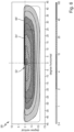
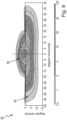
- verschiedene Ansichten einer Primäroptik des erfindungsgemäßen Lichtmoduls aus
Fig. 7 , und - Fig. 9
- eine mit dem erfindungsgemäßen Lichtmodul aus
Fig. 7 erzeugbare Lichtverteilung. -
Figur 1 zeigt einen in seiner Gesamtheit mit dem Bezugszeichen 10 bezeichneten Kraftfahrzeugscheinwerfer. Der Kraftfahrzeugscheinwerfer 10 umfasst ein Gehäuse 12, das vorzugsweise aus Kunststoff gefertigt ist. In einer Lichtaustrittsrichtung 14 weist das Gehäuse 12 eine Lichtaustrittsöffnung 16 auf, die durch eine transparente Abdeckscheibe 18 verschlossen ist. Die Abdeckscheibe 18 ist aus farblosem Kunststoff oder Glas gefertigt. Die Scheibe 18 kann ohne optisch wirksame Profile als sogenannte klare Scheibe ausgebildet sein. Alternativ kann die Scheibe 18 zumindest bereichsweise mit optisch wirksamen Profilen (z.B. Zylinderlinsen oder Prismen) versehen sein, die eine Streuung des hindurchtretenden Lichts, vorzugsweise in horizontaler Richtung bewirken. Der Scheinwerfer 10 ist zum Einbau an einer Anbauseite eines Kraftfahrzeugs vorgesehen. Zwei der gezeigten Scheinwerfer 10, die an verschiedenen Anbauseiten des Kraftfahrzeugs angeordnet sind, bilden eine erfindungsgemäße Kraftfahrzeugbeleuchtungseinrichtung. Dabei sind die an unterschiedlichen Anbauseiten eingebauten Scheinwerfer 10 bezüglich ihres allgemeinen geometrischen äußeren Erscheinungsbildes vorzugsweise spiegelsymmetrisch zueinander ausgebildet. - Im Inneren des Scheinwerfergehäuses 12 ist in dem dargestellten Beispiel ein Lichtmodul 20 angeordnet. Selbstverständlich können in dem Scheinwerfergehäuse 12 auch mehr als das dargestellte Lichtmodul 20 vorgesehen sein. Das Lichtmodul 20 erzeugt mindestens eine Lichtverteilung, die gesetzliche und regulatorische Vorgaben erfüllt.
- In dem vorliegenden Beispiel ist das Lichtmodul 20 als erfindungsgemäßes Lichtmodul ausgebildet. Das Lichtmodul 20 wird im Folgenden unter Bezugnahme auf die
Figuren 2 bis 9 im Detail erläutert. - In
Figur 2 ist das Lichtmodul 20 in einer Schnittansicht von der Seite dargestellt. - Das Lichtmodul 20 umfasst wenigstens zwei nebeneinander angeordnete Halbleiterlichtquellen 22. In
Fig. 2 ist im Schnitt lediglich eine Halbleiterlichtquelle 22 zu erkennen. - Das Lichtmodul 20 umfasst weiter wenigstens eine Primäroptikeinheit 24. Die Primäroptikeinheit 24 umfasst mindestens zwei, jeweils einer jeweiligen Halbleiterlichtquelle 22 zugeordnete Vorsatzoptiken 26.
-
Figur 3 zeigt eine beispielhafte Darstellung der Primäroptikeinheit 24. GemäßFig. 3 umfasst die Primäroptikeinheit 24 beispielhaft sieben Vorsatzoptiken 26, die gemäßFig. 3 mit den Bezugszeichen 26-1 bis 26-7 versehen sind. Erfindungsgemäß umfasst die Primäroptikeinheit 24 mindestens zwei, oder zwischen drei und neun, insbesondere zwischen fünf und sieben, nebeneinander angeordnete Lichtquellen 22 und dementsprechend mindestens zwei, oder zwischen drei und neun, insbesondere zwischen fünf und sieben, einer jeweiligen Halbleiterlichtquelle 22 zugeordnete Vorsatzoptiken 26. - Aus
Figur 3 ist ersichtlich, dass die Vorsatzoptiken 26 in Bezug auf eine horizontale Erstreckung 28 der Primäroptikeinheit 24 in oder entgegen der y-Richtung nebeneinander angeordnet sind. - Eine jeweilige Vorsatzoptik 26 umfasst einen Lichteintrittsbereich 30 mit jeweils einem zentralen Lichteintrittsbereich 32 und einen peripheren Lichteintrittsbereich 34. Der Lichteintrittsbereich 30 ist in
Fig. 3 nicht allen Vorsatzoptiken eingezeichnet. Die Lichteintrittsbereiche 30 können bei allen Vorsatzoptiken 26 identisch ausgebildet sein. - Gemäß der Ausführungsform ist vorgesehen, dass der Lichteintrittsbereich 30 rotationssymmetrisch ausgebildet ist.
- Der zentrale Lichteintrittsbereich 32 ist beispielsweise als Linse ausgebildet. Der periphere Lichteintrittsbereich 34 weitet sich ausgehend von dem zentralen Bereich 32, beispielsweise trichterförmig, leicht auf. An den peripheren Lichteintrittsbereich 34 schließt jeweils ein Lichtumlenkbereich 36 an.
- Bei den Vorsatzoptiken 26-1, 26-2, 26-3 und 26-5, 26-6, 26-7 ist der Lichtumlenkbereich 36 nicht rotationssymmetrisch ausgebildet. Die Vorsatzoptiken 26-1, 26-2, 26-3 und 26-5, 26-6, 26-7 können daher auch als Vorsatzoptiken mit unsymmetrischen Lichtumlenkbereichen 36 bezeichnet werden.
- Der unsymmetrische Lichtumlenkbereich 36 wird zunächst beispielhaft anhand der Vorsatzoptik 26-6 unter Bezugnahme auf die
Figuren 4a bis 4c erläutert. Die Erläuterungen gelten aber analog für die Vorsatzoptiken 26-5 und 26-7. -
Fig. 4a zeigt die Vorsatzoptik 26-6 als ein Abschnitt der Primäroptik 24. Der Lichtumlenkbereich 36 der Vorsatzoptik 26-6 umfasst einen ersten Teilbereich 38, vgl.Fig. 4b , und einen zweiten Teilbereich 40, vgl.Fig. 4c . Der erste Teilbereich 38 ist näher an einem Zentrum 42 der Primäroptikeinheit 24 in Bezug auf die horizontale Erstreckung der Primäroptikeinheit 24 entlang der horizontalen Achse 28 angeordnet als der zweite Teilbereich 40. Ein Zentrum 42 ist beispielhaft inFig. 3 eingezeichnet. Bei dem Zentrum muss es sich nicht zwingend um einen exakt mittig angeordneten Punkt handeln. Vielmehr wird unter einem Zentrum im Rahmen der vorliegenden Erfindung ein Punkt im Bereich einer Mitte, insbesondere auf die horizontale Erstreckung bezogen, der Primäroptikeinheit 24 verstanden. Der zweite Teilbereich 40 ist näher an einer Außenseite 44 der Primäroptikeinheit 24 in Bezug auf die horizontale Erstreckung der Primäroptikeinheit 24 angeordnet als der erste Teilbereich 38. Bei dem ersten Teilbereich 38 verläuft eine Krümmung und/oder eine Neigung des ersten Teilbereichs 38 ausgehend von dem peripheren Lichteintrittsbereich 34 flacher als eine Krümmung und/oder eine Neigung des zweiten Teilbereichs 40. Bei dem zweiten Teilbereich 40 verläuft die Krümmung und/oder die Neigung des zweiten Teilbereichs 40 ausgehend von dem peripheren Lichteintrittsbereich 34 steiler als die Krümmung und/oder die Neigung des ersten Teilbereichs 38. - Im Beispiel umfasst der Lichtumlenkbereich 36 gekrümmte Flächen. Der Lichtumlenkbereich 36 kann aber auch ebene, geneigte Flächen umfassen.
- Der erste Teilbereich 38 umfasst eine erste optische Achse 46. Der zweite Teilbereich umfasst eine zweite optische Achse 48. Durch die Variation der Krümmung und/oder der Neigung der beiden Teilbereiche 38, 40 unterscheidet sich eine Richtung der ersten optischen Achse 46 des ersten Teilbereichs 38 von der Richtung der zweiten optischen Achse 48 des zweiten Teilbereichs 40.
- Mit dem erfindungsgemäßen Lichtmodul 20 wird die Umlenkung des Lichts in von einer Hauptabstrahlrichtung des Lichtmoduls 20 abweichenden Richtungen über die beschriebene Ausgestaltung des Lichtumlenkbereichs 36 erzielt.
- Mit dem Lichtmodul 20 kann beispielsweise eine Abblendlichtverteilung 50, vgl.
Fig. 6 , erzeugt werden. - Die Abblendlichtverteilung 50 weist eine im Wesentlichen horizontal verlaufende Helldunkelgrenze 52 auf, die die Lichtverteilung nach oben begrenzt und beispielsweise entlang der Horizontalen oder knapp oberhalb oder unterhalb der Horizontalen, z.B. bei +/-1°, verläuft. Die Helldunkelgrenze 52 ist vorzugsweise als eine asymmetrische Helldunkelgrenze 52 ausgebildet, das heißt, sie weist auf der eigenen Verkehrsseite einen Abschnitt mit einem höheren Verlauf als ein Abschnitt auf der Gegenverkehrsseite auf, um eine Blendung entgegenkommender Verkehrsteilnehmer zu verringern. Der Übergang zwischen den Abschnitten der Helldunkelgrenze 52 auf der eigenen Verkehrsseite und der Gegenverkehrsseite kann beliebig ausgebildet sein, bspw. schräg ansteigend oder stufenförmig.
- Zur Erzeugung der Helldunkelgrenze 52 ist beispielsweise eine Blendenanordnung 54, vgl.
Fig. 2 , beispielsweise eine Spiegelblende vorgesehen. Die Blendenanordnung 54 ist im Strahlengang des Lichtmoduls 20 angeordnet. Wenigstens eine Oberseite 56 der Blendenanordnung 54 ist beispielsweise als spiegelnde Fläche ausgebildet. - Die Blende 54 ist in Bezug auf eine Sekundäroptik 58, beispielsweise eine Projektionslinse, so angeordnet, dass eine Kante 60 der Blendenanordnung 54 von der Sekundäroptik 58 als Helldunkelgrenze in der Abblendlichtverteilung 50 abgebildet wird.
- Die Abblendlichtverteilung 50 in
Fig. 6 wird unter Verwendung der Primäroptik 24 erzeugt. Die Abblendlichtverteilung 50 wird durch Überlagerung von einzelnen Teillichtverteilungen der jeweiligen Vorsatzoptiken 26 erzeugt. -
Fig. 5a zeigt beispielsweise eine Teillichtverteilung 62 der Abblendlichtverteilung 50 die mit der Vorsatzoptik 26-6 erzeugt wird. - Lichtstrahlen, die an den beiden Teilbereichen 38, 40 der Vorsatzoptik 26-6 umgelenkt werden, werden aufgrund der verschiedenen optischen Achsen 46, 48 der beiden Teilbereiche 38, 40 in unterschiedliche Richtungen gelenkt und beleuchten demnach unterschiedliche Bereiche der Abblendlichtverteilung 50 bzw. der Teillichtverteilung 62 der Abblendlichtverteilung 50.
- Lichtstrahlen, die an dem ersten Teilbereich 38 der Vorsatzoptik 26-6 umgelenkt werden, beleuchten einen zentralen Bereich 64 der Abblendlichtverteilung 50 bzw. der Teillichtverteilung 62 bzw. einen Teil davon auf einem vor dem Lichtmodul 20 in einem Abstand zu diesem angeordneten Messschirm im Bereich um einen Schnittpunkt einer Horizontalen H und einer Vertikalen V.
- Der zentrale Bereich 64 liegt auf dem Messschirm beispielsweise in horizontaler Richtung in einem Bereich von bis zu +/- 15°. In vertikaler Richtung liegt der zentrale Bereich 64' auf dem Messschirm etwa in einem Bereich von - 10°, insbesondere von - 7°, bis zur Helldunkelgrenze 52.
- Der erste Teilbereich 38 der Vorsatzoptik 26-6 leuchtet einen Teil 64 des zentralen Bereichs 64' aus, vgl.
Fig. 5b . Beispielsweise leuchtet der erste Teilbereich 38 einen Bereich zwischen - 12° und + 7° horizontal und zwischen - 7° bis zur Helldunkelgrenze 52 aus. Erste Teilbereiche 38 der weiteren Vorsatzoptiken, beispielsweise 26-1, 26-2, 26-3, 26-5, 26-7, leuchten beispielsweise jeweils dazu versetzt einen weiteren Teil 64 des zentralen Bereichs 64' aus. Die Ausleuchtung des gesamten zentralen Bereichs 64' der Abblendlichtverteilung 50,Fig. 6 , ergibt sich beispielsweise durch Überlagerung der von den ersten Teilbereichen der Vorsatzoptiken 26 der Primäroptik 24 ausgeleuchteten Teile 64 des zentralen Bereichs 64'. Die an den ersten Teilbereichen 38 umgelenkten Lichtstrahlen beleuchten also einen zentralen Bereich 64' der Abblendlichtverteilung 50. - Lichtstrahlen, die an dem zweiten Teilbereich 40 der Vorsatzoptik 26-6 umgelenkt werden, beleuchten in horizontaler Richtung einen breiten Bereich 66 der Abblendlichtverteilung 50 bzw. der Teillichtverteilung 62 bzw. einen Teil davon auf einem vor dem Lichtmodul 20 in einem Abstand zu diesem angeordneten Messschirm. Der breite Bereich 66 ist in horizontaler Richtung breiter ist als der von den ersten Teilbereichen 38 ausgeleuchtete zentrale Bereich 64.
- Der breite Bereich 66' der Abblendlichtverteilung 50 erstreckt sich in horizontaler Richtung bspw. in einem Bereich von bis zu -/+ 45°, insbesondere +/- 35°. In vertikaler Richtung liegt der breite Bereich 66' auf dem Messschirm etwa in einem Bereich von - 15°, insbesondere von - 12°, bis zur Helldunkelgrenze 52.
- Der zweite Teilbereich 40 der Vorsatzoptik 26-6 leuchtet einen Teil 66 des breiten Bereichs 66' aus, vgl.
Fig. 5c . Beispielsweise leuchtet der zweite Teilbereich 40 einen Bereich zwischen - 2° und + 25° horizontal und zwischen - 11° bis zur Helldunkelgrenze 52 aus. Weitere zweite Teilbereiche 40 der weiteren Vorsatzoptiken, beispielsweise 26-1, 26-2, 26-3, 26-5, 26-7, leuchten beispielsweise jeweils dazu versetzt einen weiteren Teil 66 des breiten Bereichs 66' aus. Die Ausleuchtung des gesamten breiten Bereichs 66' der Abblendlichtverteilung 50,Fig. 6 , ergibt sich beispielsweise durch Überlagerung der von den zweiten Teilbereichen der Vorsatzoptiken 26 der Primäroptik 24 ausgeleuchteten Teile 66 des breiten Bereichs 66'. Die zweiten Bereiche 40 der Vorsatzoptiken 26 sorgen also für eine besonders breite Grundlichtverteilung der Abblendlichtverteilung 50. - Die Neigung und/oder Krümmung der ersten und der zweiten Teilbereiche 38, 40 der Vorsatzoptiken 26-1, 26-2, 26-3, 26-5, 26-6, 26-7 kann variieren. Beispielsweise kann vorgesehen sein, dass bei den äußeren Vorsatzoptiken 26-1 und 26-7 der Unterschied in der Neigung und/oder Krümmung der ersten und der zweiten Teilbereiche 38, 40 am größten ist und der Unterschied nach innen bis hin zu den Vorsatzoptiken 26-3 und 26-5 abnimmt.
- Die Vorsatzoptiken 26-1, 26-2, 26-3 sind gespiegelt zu den Darstellungen in den
Figuren 5a bis 5c ausgebildet, d.h. der erste Teilbereich 38 ist auf der rechten Seite und der zweite Teilbereich 40 ist auf der linken Seite angeordnet. - Gemäß der dargestellten Ausführungsform ist vorgesehen, dass der Lichtumlenkbereich 36' der Vorsatzoptik 26-4, die in der Mitte der Vorsatzoptiken 26 angeordnet ist, rotationssymmetrisch ausgebildet ist. Dies muss nicht zwingend so sein, kann sich aber aus Symmetriegründen vorteilhaft erweisen. Bei der Vorsatzoptik 26-4 handelt es sich dementsprechend um eine Vorsatzoptik mit einem symmetrischen Lichtumlenkbereich 36'. Beispielsweise beleuchtet der Lichtumlenkbereich 36' der Vorsatzoptik 26-4 den zentralen Bereich 52 bzw. einen Teil des zentralen Bereichs 52 der Abblendlichtverteilung 50.
-
Fig. 7 zeigt eine weitere Ausführungsform des erfindungsgemäßen Lichtmoduls 20. Gemäß dieser Ausführungsform wird die Primäroptik 24 des Lichtmoduls ausFig. 2 um eine weitere Anordnung 68 von Vorsatzoptiken 70 ergänzt. Beispielhaft ist vorgesehen, dass unterhalb der Vorsatzoptiken 26 eine weitere Anordnung 68 von wenigstens zwei nebeneinander angeordneten Vorsatzoptiken 70 vorgesehen ist. Den Vorsatzoptiken 70 der weiteren Anordnung 68 ist jeweils wenigstens eine Halbleiterlichtquelle 72 zugeordnet. Beispielsweise ist eine Unterseite 56' der Blendenanordnung 54 als spiegelnde Fläche ausgebildet. - Die Primäroptik 24 kann also eine Art zweireihige Anordnung der Vorsatzoptiken 26 und der Vorsatzoptiken 70 umfassen, vgl.
Figuren 8a bis 8c . Es kann aber auch vorgesehen sein, dass zwei separate Primäroptiken (nicht dargestellt) ausgebildet sind. - In den
Fig. 8a bis 8c ist die Primäroptik 24 dargestellt. Die Primäroptik 24 umfasst in einer oberen Reihe die Vorsatzoptiken 26-1 bis 26-7. In einer unteren Reihe sind die Vorsatzoptiken 70-1 bis 70-5 angeordnet. - In der Ansicht von hinten auf die Primäroptik, vgl.
Fig. 8a , sind die Lichtumlenkbereiche 36 und die Lichteintrittsbereiche 30 der Vorsatzoptiken 26-1 bis 26-7 erkennbar. Beispielhaft sind die ersten und zweiten Teilbereiche 38, 40 der Lichtumlenkbereiche 36 der Vorsatzoptiken 26-1 und 26-7 gekennzeichnet. - Die Vorsatzoptiken 70-1 bis 70-5 können nach dem gleichen Prinzip wie die Vorsatzoptiken 26-1 bis 26-7 ausgestaltet sein. Die Vorsatzoptiken 70-1 bis 70-5 umfassen beispielsweise ebenfalls Lichteintrittsbereiche 30. Beispielsweise kann vorgesehen sein, dass Lichtumlenkbereiche 74 der Vorsatzoptiken 70-1, 70-2 und 70-4, 70-5 ebenfalls einen ersten und einen zweiten Teilbereich 76, 78 umfassen.
- Der erste Teilbereich 76 ist beispielsweise analog zu den dem ersten Teilbereich 38 näher an einem Zentrum 42 der Primäroptikeinheit 24 in Bezug auf die horizontale Erstreckung der Primäroptikeinheit 24 entlang der horizontalen Achse 28 angeordnet als der zweite Teilbereich 78.
- Bei dem ersten Teilbereich 76 verläuft eine Krümmung und/oder eine Neigung des ersten Teilbereichs 76 ausgehend von dem peripheren Lichteintrittsbereich 34 flacher als eine Krümmung und/oder eine Neigung des zweiten Teilbereichs 78. Bei dem zweiten Teilbereich 78 verläuft die Krümmung und/oder die Neigung des zweiten Teilbereichs 78 ausgehend von dem peripheren Lichteintrittsbereich 34 steiler als die Krümmung und/oder die Neigung des ersten Teilbereichs 76. Dadurch unterscheiden sich analog auch optischen Achsen des ersten und des zweiten Teilbereichs 76, 78 voneinander.
- Die Teilbereiche 76, 78 sind so ausgebildet, dass mit dem ersten Teilbereich 76 ein zentraler Bereich einer Teillichtverteilung und mit dem zweiten Teilbereich 78 ein breiter Bereich einer Teillichtverteilung ausgeleuchtet wird.
- Mit der weiteren Anordnung 68 wird beispielsweise eine Teillichtverteilung einer Fernlichtverteilung erzeugt. Beispielsweise kann mit der weiteren Anordnung 68 eine Teillichtverteilung erzeugt werden, die die Abblendlichtverteilung 50 um einen weiteren Bereich 80 oberhalb der Horizontalen zu einer Fernlichtverteilung 82 ergänzt, vgl.
Fig. 9 . - Die ersten Teilbereiche 76 der Vorsatzoptiken 70-1, 70-2 und 70-4, 70-5 beleuchten beispielsweise jeweils einen Teil des zentralen Bereichs, der sich auf einem Messschirm in einem Bereich von etwa -/+ 10° horizontal und von der Helldunkelgrenze bis + 5° vertikal erstreckt.
- Die zweiten Teilbereiche 78 der Vorsatzoptiken 70-1, 70-2 und 70-4, 70-5 beleuchten beispielsweise jeweils einen Teil eines breiten Bereichs, der sich auf einem Messschirm in einem Bereich von -/+ 22° horizontal und von der Helldunkelgrenze bis +8° vertikal erstreckt.
- Die Teillichtverteilung 80 ergibt sich durch Überlagerung der von den ersten und zweiten Teilbereichen 76, 78 der Vorsatzoptiken 70 ausgeleuchteten Teile.
- Eine mittig angeordnete Vorsatzoptik 70-3 umfasst im Beispiel einen achsensymmetrischen Umlenkbereich 84. In diesem Fall sind die Teilbereiche 84', 84" symmetrisch zu einer, im Beispiel vertikal verlaufenden Ebene 86 ausgebildet.
- Beispielsweise beleuchten die beiden Teilbereiche 84', 84" der Vorsatzoptik 70-3 den zentralen Bereich der Teillichtverteilung 80.
- Gemäß der dargestellten Ausführungsform ist vorgesehen, dass die jeweiligen Lichtumlenkbereiche 36, 74 und 84 einer jeweiligen Vorsatzoptik 26, 70 entlang einer vertikalen Ebene 88 senkrecht zu der horizontalen Achse 28, vgl. beispielhaft Vorsatzoptik 70-1, jeweils in den ersten und den zweiten Teilbereich unterteilt ist. Die Unterteilung kann auch entlang einer schräg zu der horizontalen Achse 28 verlaufenden Ebene erfolgen.
- Die Ebene 88 verläuft dabei nicht zwingend durch einen Mittelpunkt des rotationssymmetrischen Lichteintrittsbereichs 30. Die Ebene kann auch entlang der horizontalen Achse 28 versetzt verlaufen.
- Bei den Vorsatzoptiken 26, 70 ist vorgesehen, dass die ersten und zweiten Teilbereiche bei der jeweiligen Vorsatzoptik stetig ineinander übergehen. Ein jeweiliger Lichtumlenkbereich 36, 74, 84 der Vorsatzoptiken 26, 70 weist also keine Stufen oder Kanten auf.
- Die
Figuren 8b und8c zeigen die Primäroptik 24 in einer perspektivischen Ansicht und in einer Ansicht von vorne. Die Primäroptik umfasst gemäß der dargestellten Ausführungsform eine obere Lichtaustrittsfläche 90 und eine untere Lichtaustrittsfläche 92. - Die Lichtaustrittsflächen 90, 92 könnten aber auch zu einer gemeinsamen Lichtaustrittsfläche verbunden sein.
- Die Lichtaustrittsfläche 90 umfasst Lichtaustrittsflächenbereiche 90-1 bis 90-7. Diese sind jeweils einer Vorsatzoptik 26-1 bis 26-7 zugeordnet. Die Lichtaustrittsfläche 92 umfasst Lichtaustrittsflächenbereiche 92-1 bis 92-5. Diese sind jeweils einer Vorsatzoptik 70-1 bis 70-5 zugeordnet. Es ist vorgesehen, dass die Lichtaustrittsflächenbereiche 90-1 bis 90-7 und 92-1 bis 92-5 stetig ineinander übergehen. Die Primäroptik 24 umfasst also zwei stetige Lichtaustrittsflächen 90, 92. Die Lichtaustrittsflächen 90, 92 der Primäroptik 24 weisen also keine Stufen oder Kanten auf.
Claims (13)
- Lichtmodul (20) für einen Kraftfahrzeugscheinwerfer (10) mit mindestens zwei Halbleiterlichtquellen (22; 72), und wenigstens einer Primäroptikeinheit (24), wobei die Primäroptikeinheit (24) mindestens zwei, jeweils einer jeweiligen Halbleiterlichtquelle (22, 72) zugeordnete Vorsatzoptiken (26; 70) umfasst, wobei die Vorsatzoptiken (26; 70) in Bezug auf eine horizontale Erstreckung der Primäroptikeinheit (24) nebeneinander angeordnet sind, und wobei eine jeweilige Vorsatzoptik (26; 70) einen Lichteintrittsbereich (30) mit jeweils einem zentralen Lichteintrittsbereich (32) und einem peripheren Lichteintrittsbereich (34) umfasst, und einen an den peripheren Lichteintrittsbereich (34) anschließenden Lichtumlenkbereich (36, 74), wobei der Lichtumlenkbereich (36, 74) einer jeweiligen Vorsatzoptik (26-1, 26-2, 26-3, 26-5, 26-6, 26-7; 70-1, 70-2, 70-4, 70-5) jeweils einen ersten Teilbereich (38; 76) und einen zweiten Teilbereich (40; 78) umfasst, wobei der erste Teilbereich (38; 76) näher an einem Zentrum (42) der Primäroptikeinheit (24) in Bezug auf die horizontale Erstreckung der Primäroptikeinheit (24) entlang einer horizontalen Achse (28) angeordnet ist als der zweite Teilbereich (40; 78) und der zweite Teilbereich (40; 78) näher an einer Außenseite (44) der Primäroptikeinheit (24) in Bezug auf die horizontale Erstreckung der Primäroptikeinheit (24) angeordnet ist als der erste Teilbereich (38; 76), dadurch gekennzeichnet, dass eine Krümmung und/oder eine Neigung des ersten Teilbereichs (38; 76) ausgehend von dem peripheren Lichteintrittsbereich (34) flacher verläuft als eine Krümmung und/oder eine Neigung des zweiten Teilbereichs (40; 78), und die Krümmung und/oder die Neigung des zweiten Teilbereichs (40; 78) ausgehend von dem peripheren Lichteintrittsbereich (34) steiler verläuft als die Krümmung und/oder die Neigung des ersten Teilbereichs (38; 76), sodass sich eine Richtung einer ersten optischen Achse (46) des ersten Teilbereichs (38; 76) von einer Richtung einer zweiten optischen Achse (48) des zweiten Teilbereichs (40; 78) unterscheidet.
- Lichtmodul (20) nach Anspruch 1, dadurch gekennzeichnet, dass mit dem Lichtmodul (20) eine Abblendlichtverteilung (50) oder eine Teillichtverteilung einer Abblendlichtverteilung (50) erzeugt wird, und dass Lichtstrahlen die an den ersten Teilbereichen (38) der Vorsatzoptiken (26-1, 26-2, 26-3, 26-5, 26-6, 26-7) umgelenkt werden, einen zentralen Bereich (64') der Abblendlichtverteilung (50), auf einem vor dem Lichtmodul (20) in einem Abstand zu diesem angeordneten Messschirm im Bereich um einen Schnittpunkt (HV) einer Horizontalen (HH) und einer Vertikalen (VV), ausleuchten.
- Lichtmodul (20) nach Anspruch 2, dadurch gekennzeichnet, dass Lichtstrahlen die an den zweiten Teilbereichen (40) der Vorsatzoptiken (26-1, 26-2, 26-3, 26-5, 26-6, 26-7) umgelenkt werden, in horizontaler Richtung einen breiten Bereich (66') der Abblendlichtverteilung (50) ausleuchten, wobei der breite Bereich (66') in horizontaler Richtung breiter ist als der von den ersten Teilbereichen (38) ausgeleuchtete zentrale Bereich (64').
- Lichtmodul (20) nach einem der Ansprüche 2 oder 3, dadurch gekennzeichnet, dass mit einer jeweiligen Vorsatzoptik (26-1, 26-2, 26-3, 26-5, 26-6, 26-7) eine Teillichtverteilung (62) der Abblendlichtverteilung (50) erzeugt wird.
- Lichtmodul (20) nach wenigstens einem der vorhergehenden Ansprüche, dadurch gekennzeichnet, dass der erste Teilbereich (38; 76) und der zweite Teilbereich (40; 78) einer jeweiligen Vorsatzoptik (26, 70) stetig ineinander übergehen.
- Lichtmodul (20) nach wenigstens einem der vorhergehenden Ansprüche, dadurch gekennzeichnet, dass ein jeweiliger Lichtumlenkbereich (36; 74) einer jeweiligen Vorsatzoptik (26-1, 26-2, 26-3, 26-5, 26-6, 26-7; 70-1, 70-2, 70-4, 70-5) entlang einer vertikalen Ebene (88) senkrecht zu der horizontalen Achse (28) oder entlang einer schrägen Ebene schräg zu der horizontalen Achse (28) in den ersten Teilbereich (38; 76) und den zweiten Teilbereich (40; 78) unterteilt ist.
- Lichtmodul (20) nach wenigstens einem der vorhergehenden Ansprüche, dadurch gekennzeichnet, dass die Primäroptikeinheit (24) eine zwischen den wenigstens zwei weiteren Vorsatzoptiken (26-1, 26-2, 26-3, 26-5, 26-6, 26-7; 70-1, 70-2, 70-4, 70-5) mittig angeordnete Vorsatzoptik (26-4; 70-3) umfasst, wobei die mittig angeordnete Vorsatzoptik (26-4; 70-3) einen symmetrisch, insbesondere rotationssymmetrisch oder achssymmetrisch, ausgebildeten Lichtumlenkbereich (36'; 84) umfasst.
- Lichtmodul (20) nach wenigstens einem der vorhergehenden Ansprüche, dadurch gekennzeichnet, dass zwischen drei und neun, insbesondere zwischen fünf und sieben, nebeneinander angeordnete Lichtquellen (22, 72) vorgesehen sind, wobei die Primäroptikeinheit (24) dementsprechend jeweils zwischen drei und neun, insbesondere zwischen fünf und sieben, einer jeweiligen Halbleiterlichtquelle (22, 72) zugeordnete Vorsatzoptiken (26, 70) umfasst.
- Lichtmodul (20) nach wenigstens einem der vorhergehenden Ansprüche, dadurch gekennzeichnet, dass die Primäroptikeinheit (24) eine Lichtaustrittsfläche (90; 92) umfasst und einer jeweiligen Vorsatzoptik (26; 70) zugeordnete Lichtaustrittsflächenbereiche (90-1, 90-2, 90-3, 90-4, 90-5, 90-6, 90-7; 92-1, 92-2, 92-3, 92-4, 92-5) stetig ineinander übergehen.
- Lichtmodul (20) nach wenigstens einem der vorhergehenden Ansprüche, dadurch gekennzeichnet, dass oberhalb oder unterhalb der wenigstens zwei Vorsatzoptiken (26; 70) eine weitere Anordnung (68) von wenigstens zwei nebeneinander angeordneten Vorsatzoptiken (70; 26) vorgesehen ist.
- Lichtmodul (20) nach Anspruch 10, dadurch gekennzeichnet, dass mit der weiteren Anordnung (68) eine Fernlichtverteilung (82) oder eine Teillichtverteilung (80) einer Fernlichtverteilung (82) erzeugt wird.
- Lichtmodul (20) nach wenigstens einem der vorhergehenden Ansprüche, dadurch gekennzeichnet, dass eine Blendenanordnung (54), insbesondere umfassend eine Spiegelblende, vorgesehen ist.
- Lichtmodul (20) nach wenigstens einem der vorhergehenden Ansprüche, dadurch gekennzeichnet, dass eine Sekundäroptik (58), insbesondere eine Projektionslinse, vorgesehen ist.
Applications Claiming Priority (1)
| Application Number | Priority Date | Filing Date | Title |
|---|---|---|---|
| DE102022111039.7A DE102022111039A1 (de) | 2022-05-04 | 2022-05-04 | Lichtmodul mit mehreren Vorsatzoptiken |
Publications (2)
| Publication Number | Publication Date |
|---|---|
| EP4273440A1 EP4273440A1 (de) | 2023-11-08 |
| EP4273440B1 true EP4273440B1 (de) | 2024-11-20 |
Family
ID=86226485
Family Applications (1)
| Application Number | Title | Priority Date | Filing Date |
|---|---|---|---|
| EP23169615.4A Active EP4273440B1 (de) | 2022-05-04 | 2023-04-24 | Lichtmodul mit mehreren vorsatzoptiken |
Country Status (4)
| Country | Link |
|---|---|
| US (1) | US11953172B2 (de) |
| EP (1) | EP4273440B1 (de) |
| CN (1) | CN117006437A (de) |
| DE (1) | DE102022111039A1 (de) |
Families Citing this family (2)
| Publication number | Priority date | Publication date | Assignee | Title |
|---|---|---|---|---|
| KR20240063649A (ko) * | 2022-11-03 | 2024-05-10 | 현대모비스 주식회사 | 차량용 램프 |
| DE102024134295A1 (de) * | 2024-11-21 | 2026-05-21 | Marelli Germany Gmbh | Lichtmodul für einen Kraftfahrzeugscheinwerfer |
Family Cites Families (8)
| Publication number | Priority date | Publication date | Assignee | Title |
|---|---|---|---|---|
| US6443594B1 (en) * | 2000-03-31 | 2002-09-03 | Koninklijke Philips Electronics N.V. | One-piece lens arrays for collimating and focusing light and led light generators using same |
| US6527411B1 (en) * | 2000-08-01 | 2003-03-04 | Visteon Corporation | Collimating lamp |
| WO2011154470A1 (de) * | 2010-06-09 | 2011-12-15 | Automotive Lighting Reutlingen Gmbh | Vorsatzoptik aus transparentem material zum bündeln von licht, linsenarray mit mindestens einer solchen vorsatzoptik und lichtmodul mit einem solchen linsenarray |
| DE102013207850A1 (de) * | 2013-04-29 | 2014-10-30 | Automotive Lighting Reutlingen Gmbh | Lichtmodul für einen Kraftfahrzeugscheinwerfer |
| CN108603644B (zh) * | 2016-01-13 | 2020-11-06 | 三菱电机株式会社 | 前照灯模块和前照灯装置 |
| CN106439680A (zh) * | 2016-09-29 | 2017-02-22 | 马瑞利汽车零部件(芜湖)有限公司 | 一种形成近光光型的透镜 |
| US10851959B2 (en) * | 2017-11-22 | 2020-12-01 | Stanley Electric Co., Ltd. | Vehicle headlight |
| US12072075B2 (en) * | 2020-04-17 | 2024-08-27 | Hasco Vision Technology Co., Ltd. | Primary optical structure, high-beam lighting device, anti-glare high-beam lamp and vehicle |
-
2022
- 2022-05-04 DE DE102022111039.7A patent/DE102022111039A1/de not_active Withdrawn
-
2023
- 2023-04-17 CN CN202310404396.5A patent/CN117006437A/zh active Pending
- 2023-04-24 EP EP23169615.4A patent/EP4273440B1/de active Active
- 2023-05-04 US US18/312,040 patent/US11953172B2/en active Active
Also Published As
| Publication number | Publication date |
|---|---|
| US11953172B2 (en) | 2024-04-09 |
| EP4273440A1 (de) | 2023-11-08 |
| US20230358383A1 (en) | 2023-11-09 |
| DE102022111039A1 (de) | 2023-11-09 |
| CN117006437A (zh) | 2023-11-07 |
Similar Documents
| Publication | Publication Date | Title |
|---|---|---|
| EP2799761B1 (de) | Lichtmodul für einen kraftfahrzeugscheinwerfer | |
| EP2846077B1 (de) | Projektionsoptik zum Einsatz in einem LED-Modul eines Kraftfahrzeugscheinwerfers, sowie LED-Modul und Kraftfahrzeugscheinwerfer mit einer solchen Projektionsoptik | |
| DE102014205994B4 (de) | Lichtmodul mit Halbleiterlichtquelle und Vorsatzoptik und Kraftfahrzeugscheinwerfer mit einem solchen Lichtmodul | |
| EP2893249B1 (de) | Leuchteinheit für einen scheinwerfer | |
| DE60302708T2 (de) | Kfz-Scheinwerfer nach dem Projektionsprinzip mit einer sekundären Lichtquelle | |
| DE102009010558A1 (de) | Lichtmodul für eine Beleuchtungseinrichtung | |
| EP0723108A1 (de) | Scheinwerfer für Fahrzeuge | |
| EP0937942A2 (de) | Scheinwerfer für Fahrzeuge nach dem Projektionsprinzip | |
| DE102007023076B4 (de) | Beleuchtungseinrichtung für Kraftfahrzeuge | |
| EP2420728A1 (de) | Projektionsscheinwerfer mit gezielt abgeschwächtem Lichtintensitätsgradienten an der Hell-Dunkel-Grenze | |
| DE19961942A1 (de) | Scheinwerferanlage für Fahrzeuge zur Erzeugung von Lichtbündeln mit unterschiedlicher Charakteristik | |
| EP3301350B1 (de) | Lichtmodul für einen kraftfahrzeugscheinwerfer | |
| DE4307110C2 (de) | Kraftfahrzeugscheinwerfer mit wenigstens einer bewegbaren Abschirmvorrichtung | |
| EP2984396A2 (de) | Leuchteinheit mit blende mit zumindest einem lichtfenster | |
| EP4273440A1 (de) | Lichtmodul mit mehreren vorsatzoptiken | |
| DE2828856C2 (de) | Scheinwerfer für Kraftfahrzeuge | |
| DE2923316C2 (de) | Kraftfahrzeug-Scheinwerfer mit gerippter Streuscheibe und Verfahren zu deren Herstellung | |
| DE19602978B4 (de) | Fahrzeug-Scheinwerfer | |
| DE19905115A1 (de) | Scheinwerfer für Fahrzeuge | |
| DE3417034C2 (de) | ||
| EP3870894B1 (de) | Leuchteinheit für einen kfz-scheinwerfer | |
| DE10312364B4 (de) | Scheinwerfer zur Erzeugung einer deutlichen Hell-Dunkel-Grenze auf der Fahrbahn | |
| AT519356B1 (de) | Lichtmodul für einen Kraftfahrzeugscheinwerfer | |
| DE4129955C2 (de) | Kraftfahrzeug-Beleuchtungseinrichtung mit Lichtleiterlementen | |
| DE10005652A1 (de) | Kraftfahrzeugscheinwerfer vom Ellipsoid-Typ zur Erzeugung eines Lichtbündels ohne Hell-Dunkel-Grenze |
Legal Events
| Date | Code | Title | Description |
|---|---|---|---|
| PUAI | Public reference made under article 153(3) epc to a published international application that has entered the european phase |
Free format text: ORIGINAL CODE: 0009012 |
|
| STAA | Information on the status of an ep patent application or granted ep patent |
Free format text: STATUS: THE APPLICATION HAS BEEN PUBLISHED |
|
| AK | Designated contracting states |
Kind code of ref document: A1 Designated state(s): AL AT BE BG CH CY CZ DE DK EE ES FI FR GB GR HR HU IE IS IT LI LT LU LV MC ME MK MT NL NO PL PT RO RS SE SI SK SM TR |
|
| STAA | Information on the status of an ep patent application or granted ep patent |
Free format text: STATUS: REQUEST FOR EXAMINATION WAS MADE |
|
| 17P | Request for examination filed |
Effective date: 20240415 |
|
| RBV | Designated contracting states (corrected) |
Designated state(s): AL AT BE BG CH CY CZ DE DK EE ES FI FR GB GR HR HU IE IS IT LI LT LU LV MC ME MK MT NL NO PL PT RO RS SE SI SK SM TR |
|
| GRAP | Despatch of communication of intention to grant a patent |
Free format text: ORIGINAL CODE: EPIDOSNIGR1 |
|
| STAA | Information on the status of an ep patent application or granted ep patent |
Free format text: STATUS: GRANT OF PATENT IS INTENDED |
|
| RIC1 | Information provided on ipc code assigned before grant |
Ipc: F21S 41/151 20180101ALI20240606BHEP Ipc: F21S 41/27 20180101ALI20240606BHEP Ipc: F21S 41/265 20180101ALI20240606BHEP Ipc: F21S 41/32 20180101ALI20240606BHEP Ipc: F21S 41/147 20180101AFI20240606BHEP |
|
| INTG | Intention to grant announced |
Effective date: 20240709 |
|
| GRAS | Grant fee paid |
Free format text: ORIGINAL CODE: EPIDOSNIGR3 |
|
| GRAA | (expected) grant |
Free format text: ORIGINAL CODE: 0009210 |
|
| STAA | Information on the status of an ep patent application or granted ep patent |
Free format text: STATUS: THE PATENT HAS BEEN GRANTED |
|
| AK | Designated contracting states |
Kind code of ref document: B1 Designated state(s): AL AT BE BG CH CY CZ DE DK EE ES FI FR GB GR HR HU IE IS IT LI LT LU LV MC ME MK MT NL NO PL PT RO RS SE SI SK SM TR |
|
| P01 | Opt-out of the competence of the unified patent court (upc) registered |
Free format text: CASE NUMBER: APP_55790/2024 Effective date: 20241011 |
|
| REG | Reference to a national code |
Ref country code: GB Ref legal event code: FG4D Free format text: NOT ENGLISH |
|
| REG | Reference to a national code |
Ref country code: CH Ref legal event code: EP |
|
| REG | Reference to a national code |
Ref country code: DE Ref legal event code: R081 Ref document number: 502023000306 Country of ref document: DE Owner name: MARELLI GERMANY GMBH, DE Free format text: FORMER OWNER: ANMELDERANGABEN UNKLAR / UNVOLLSTAENDIG, 80297 MUENCHEN, DE Ref country code: DE Ref legal event code: R081 Ref document number: 502023000306 Country of ref document: DE Owner name: MARELLI GERMANY GMBH, DE Free format text: FORMER OWNER: MARELLI AUTOMOTIVE LIGHTING REUTLINGEN (GERMANY) GMBH, 72762 REUTLINGEN, DE Ref country code: DE Ref legal event code: R096 Ref document number: 502023000306 Country of ref document: DE |
|
| REG | Reference to a national code |
Ref country code: IE Ref legal event code: FG4D Free format text: LANGUAGE OF EP DOCUMENT: GERMAN |
|
| RAP4 | Party data changed (patent owner data changed or rights of a patent transferred) |
Owner name: MARELLI GERMANY GMBH |
|
| REG | Reference to a national code |
Ref country code: LT Ref legal event code: MG9D |
|
| REG | Reference to a national code |
Ref country code: NL Ref legal event code: MP Effective date: 20241120 |
|
| PG25 | Lapsed in a contracting state [announced via postgrant information from national office to epo] |
Ref country code: IS Free format text: LAPSE BECAUSE OF FAILURE TO SUBMIT A TRANSLATION OF THE DESCRIPTION OR TO PAY THE FEE WITHIN THE PRESCRIBED TIME-LIMIT Effective date: 20250320 Ref country code: PT Free format text: LAPSE BECAUSE OF FAILURE TO SUBMIT A TRANSLATION OF THE DESCRIPTION OR TO PAY THE FEE WITHIN THE PRESCRIBED TIME-LIMIT Effective date: 20250320 Ref country code: HR Free format text: LAPSE BECAUSE OF FAILURE TO SUBMIT A TRANSLATION OF THE DESCRIPTION OR TO PAY THE FEE WITHIN THE PRESCRIBED TIME-LIMIT Effective date: 20241120 |
|
| PG25 | Lapsed in a contracting state [announced via postgrant information from national office to epo] |
Ref country code: NL Free format text: LAPSE BECAUSE OF FAILURE TO SUBMIT A TRANSLATION OF THE DESCRIPTION OR TO PAY THE FEE WITHIN THE PRESCRIBED TIME-LIMIT Effective date: 20241120 Ref country code: FI Free format text: LAPSE BECAUSE OF FAILURE TO SUBMIT A TRANSLATION OF THE DESCRIPTION OR TO PAY THE FEE WITHIN THE PRESCRIBED TIME-LIMIT Effective date: 20241120 |
|
| PG25 | Lapsed in a contracting state [announced via postgrant information from national office to epo] |
Ref country code: BG Free format text: LAPSE BECAUSE OF FAILURE TO SUBMIT A TRANSLATION OF THE DESCRIPTION OR TO PAY THE FEE WITHIN THE PRESCRIBED TIME-LIMIT Effective date: 20241120 |
|
| PG25 | Lapsed in a contracting state [announced via postgrant information from national office to epo] |
Ref country code: ES Free format text: LAPSE BECAUSE OF FAILURE TO SUBMIT A TRANSLATION OF THE DESCRIPTION OR TO PAY THE FEE WITHIN THE PRESCRIBED TIME-LIMIT Effective date: 20241120 |
|
| PG25 | Lapsed in a contracting state [announced via postgrant information from national office to epo] |
Ref country code: NO Free format text: LAPSE BECAUSE OF FAILURE TO SUBMIT A TRANSLATION OF THE DESCRIPTION OR TO PAY THE FEE WITHIN THE PRESCRIBED TIME-LIMIT Effective date: 20250220 |
|
| PG25 | Lapsed in a contracting state [announced via postgrant information from national office to epo] |
Ref country code: LV Free format text: LAPSE BECAUSE OF FAILURE TO SUBMIT A TRANSLATION OF THE DESCRIPTION OR TO PAY THE FEE WITHIN THE PRESCRIBED TIME-LIMIT Effective date: 20241120 Ref country code: GR Free format text: LAPSE BECAUSE OF FAILURE TO SUBMIT A TRANSLATION OF THE DESCRIPTION OR TO PAY THE FEE WITHIN THE PRESCRIBED TIME-LIMIT Effective date: 20250221 |
|
| PG25 | Lapsed in a contracting state [announced via postgrant information from national office to epo] |
Ref country code: PL Free format text: LAPSE BECAUSE OF FAILURE TO SUBMIT A TRANSLATION OF THE DESCRIPTION OR TO PAY THE FEE WITHIN THE PRESCRIBED TIME-LIMIT Effective date: 20241120 |
|
| PG25 | Lapsed in a contracting state [announced via postgrant information from national office to epo] |
Ref country code: RS Free format text: LAPSE BECAUSE OF FAILURE TO SUBMIT A TRANSLATION OF THE DESCRIPTION OR TO PAY THE FEE WITHIN THE PRESCRIBED TIME-LIMIT Effective date: 20250220 |
|
| PG25 | Lapsed in a contracting state [announced via postgrant information from national office to epo] |
Ref country code: SM Free format text: LAPSE BECAUSE OF FAILURE TO SUBMIT A TRANSLATION OF THE DESCRIPTION OR TO PAY THE FEE WITHIN THE PRESCRIBED TIME-LIMIT Effective date: 20241120 |
|
| PGFP | Annual fee paid to national office [announced via postgrant information from national office to epo] |
Ref country code: DE Payment date: 20250319 Year of fee payment: 3 |
|
| PG25 | Lapsed in a contracting state [announced via postgrant information from national office to epo] |
Ref country code: DK Free format text: LAPSE BECAUSE OF FAILURE TO SUBMIT A TRANSLATION OF THE DESCRIPTION OR TO PAY THE FEE WITHIN THE PRESCRIBED TIME-LIMIT Effective date: 20241120 |
|
| PG25 | Lapsed in a contracting state [announced via postgrant information from national office to epo] |
Ref country code: EE Free format text: LAPSE BECAUSE OF FAILURE TO SUBMIT A TRANSLATION OF THE DESCRIPTION OR TO PAY THE FEE WITHIN THE PRESCRIBED TIME-LIMIT Effective date: 20241120 |
|
| PG25 | Lapsed in a contracting state [announced via postgrant information from national office to epo] |
Ref country code: RO Free format text: LAPSE BECAUSE OF FAILURE TO SUBMIT A TRANSLATION OF THE DESCRIPTION OR TO PAY THE FEE WITHIN THE PRESCRIBED TIME-LIMIT Effective date: 20241120 |
|
| PGFP | Annual fee paid to national office [announced via postgrant information from national office to epo] |
Ref country code: AT Payment date: 20250721 Year of fee payment: 3 |
|
| PG25 | Lapsed in a contracting state [announced via postgrant information from national office to epo] |
Ref country code: SK Free format text: LAPSE BECAUSE OF FAILURE TO SUBMIT A TRANSLATION OF THE DESCRIPTION OR TO PAY THE FEE WITHIN THE PRESCRIBED TIME-LIMIT Effective date: 20241120 |
|
| PG25 | Lapsed in a contracting state [announced via postgrant information from national office to epo] |
Ref country code: CZ Free format text: LAPSE BECAUSE OF FAILURE TO SUBMIT A TRANSLATION OF THE DESCRIPTION OR TO PAY THE FEE WITHIN THE PRESCRIBED TIME-LIMIT Effective date: 20241120 |
|
| PG25 | Lapsed in a contracting state [announced via postgrant information from national office to epo] |
Ref country code: IT Free format text: LAPSE BECAUSE OF FAILURE TO SUBMIT A TRANSLATION OF THE DESCRIPTION OR TO PAY THE FEE WITHIN THE PRESCRIBED TIME-LIMIT Effective date: 20241120 |
|
| REG | Reference to a national code |
Ref country code: DE Ref legal event code: R097 Ref document number: 502023000306 Country of ref document: DE |
|
| PG25 | Lapsed in a contracting state [announced via postgrant information from national office to epo] |
Ref country code: SE Free format text: LAPSE BECAUSE OF FAILURE TO SUBMIT A TRANSLATION OF THE DESCRIPTION OR TO PAY THE FEE WITHIN THE PRESCRIBED TIME-LIMIT Effective date: 20241120 |
|
| PLBE | No opposition filed within time limit |
Free format text: ORIGINAL CODE: 0009261 |
|
| STAA | Information on the status of an ep patent application or granted ep patent |
Free format text: STATUS: NO OPPOSITION FILED WITHIN TIME LIMIT |
|
| 26N | No opposition filed |
Effective date: 20250821 |
|
| PG25 | Lapsed in a contracting state [announced via postgrant information from national office to epo] |
Ref country code: LU Free format text: LAPSE BECAUSE OF NON-PAYMENT OF DUE FEES Effective date: 20250424 |
|
| PG25 | Lapsed in a contracting state [announced via postgrant information from national office to epo] |
Ref country code: MC Free format text: LAPSE BECAUSE OF FAILURE TO SUBMIT A TRANSLATION OF THE DESCRIPTION OR TO PAY THE FEE WITHIN THE PRESCRIBED TIME-LIMIT Effective date: 20241120 |
|
| REG | Reference to a national code |
Ref country code: BE Ref legal event code: MM Effective date: 20250430 |
|
| PG25 | Lapsed in a contracting state [announced via postgrant information from national office to epo] |
Ref country code: BE Free format text: LAPSE BECAUSE OF NON-PAYMENT OF DUE FEES Effective date: 20250430 |
|
| PG25 | Lapsed in a contracting state [announced via postgrant information from national office to epo] |
Ref country code: IE Free format text: LAPSE BECAUSE OF NON-PAYMENT OF DUE FEES Effective date: 20250424 |
|
| PGFP | Annual fee paid to national office [announced via postgrant information from national office to epo] |
Ref country code: FR Payment date: 20260320 Year of fee payment: 4 |