EP4273377A1 - Hydraulische betriebseinrichtung für einen kühllüfter eines nutzfahrzeugs - Google Patents
Hydraulische betriebseinrichtung für einen kühllüfter eines nutzfahrzeugs Download PDFInfo
- Publication number
- EP4273377A1 EP4273377A1 EP23168158.6A EP23168158A EP4273377A1 EP 4273377 A1 EP4273377 A1 EP 4273377A1 EP 23168158 A EP23168158 A EP 23168158A EP 4273377 A1 EP4273377 A1 EP 4273377A1
- Authority
- EP
- European Patent Office
- Prior art keywords
- hydraulic
- pressure
- operating device
- hydraulic motor
- valve
- Prior art date
- Legal status (The legal status is an assumption and is not a legal conclusion. Google has not performed a legal analysis and makes no representation as to the accuracy of the status listed.)
- Granted
Links
Images

Classifications
-
- F—MECHANICAL ENGINEERING; LIGHTING; HEATING; WEAPONS; BLASTING
- F01—MACHINES OR ENGINES IN GENERAL; ENGINE PLANTS IN GENERAL; STEAM ENGINES
- F01P—COOLING OF MACHINES OR ENGINES IN GENERAL; COOLING OF INTERNAL-COMBUSTION ENGINES
- F01P7/00—Controlling of coolant flow
- F01P7/02—Controlling of coolant flow the coolant being cooling-air
- F01P7/04—Controlling of coolant flow the coolant being cooling-air by varying pump speed, e.g. by changing pump-drive gear ratio
- F01P7/044—Controlling of coolant flow the coolant being cooling-air by varying pump speed, e.g. by changing pump-drive gear ratio using hydraulic drives
-
- F—MECHANICAL ENGINEERING; LIGHTING; HEATING; WEAPONS; BLASTING
- F01—MACHINES OR ENGINES IN GENERAL; ENGINE PLANTS IN GENERAL; STEAM ENGINES
- F01P—COOLING OF MACHINES OR ENGINES IN GENERAL; COOLING OF INTERNAL-COMBUSTION ENGINES
- F01P3/00—Liquid cooling
- F01P3/20—Cooling circuits not specific to a single part of engine or machine
-
- F—MECHANICAL ENGINEERING; LIGHTING; HEATING; WEAPONS; BLASTING
- F01—MACHINES OR ENGINES IN GENERAL; ENGINE PLANTS IN GENERAL; STEAM ENGINES
- F01P—COOLING OF MACHINES OR ENGINES IN GENERAL; COOLING OF INTERNAL-COMBUSTION ENGINES
- F01P5/00—Pumping cooling-air or liquid coolants
- F01P5/02—Pumping cooling-air; Arrangements of cooling-air pumps, e.g. fans or blowers
- F01P5/04—Pump-driving arrangements
Definitions
- the invention relates to a hydraulic operating device for a cooling fan of a commercial vehicle.
- Such an operating device is used, among other things, in agricultural tractors from the manufacturer John Deere for cooling charge air that is compressed by a turbocharger and fed to a supercharged diesel engine.
- the operating device known in this respect has a hydraulic motor which drives a fan wheel to generate an axial air flow passing through an intercooler.
- the hydraulic motor is operated using a specially designed hydraulic pump with a constant delivery volume.
- a bypass valve in the form of an electrically controllable pressure control valve is connected in parallel with the hydraulic motor.
- agricultural tractors are usually also equipped with a (main) hydraulic system that is used to operate various vehicle or work-related functions.
- the hydraulic system in turn comprises a hydraulic pump in the form of a hydraulic variable displacement pump, which is fed from a reservoir for hydraulic fluid.
- the hydraulic variable pump has a pressure control input, which makes it possible to adjust the delivery volume as desired based on a reported hydraulic pressure.
- the object of the present invention is therefore to design a hydraulic operating device for a cooling fan of a commercial vehicle with regard to optimizing the required installation space and energy efficiency.
- the hydraulic operating device for a cooling fan of a commercial vehicle comprises a hydraulic motor and a fan unit that can be driven by the hydraulic motor for generating a cooling air flow, a hydraulic supply that can be adjusted in terms of its delivery volume in accordance with a pressure feedback for providing pressurized hydraulic fluid, and a control valve for setting a through the volume flow passing through the hydraulic motor depending on a control signal representing a cooling requirement, with a sensor line branched off in a supply line between the control valve and the hydraulic motor leading to a pressure control input of the hydraulic supply provided for pressure feedback.
- the control valve is opened or closed depending on the control signal leads to a corresponding increase or decrease in the volume flow passing through the hydraulic motor.
- the change in the hydraulic pressure that occurs in the supply line is reported back via the sensor line to the pressure control input of the hydraulic supply, to which it responds with a corresponding increase or decrease in the delivery volume.
- the cooling air flow generated by the fan unit passes, for example, through an intercooler, which serves to cool charge air that is compressed by a turbocharger and supplied to a supercharged diesel engine.
- the fan unit is designed as an axial or radial fan.
- a throttle element designed as a constant throttle in the form of an orifice or nozzle, which limits hydraulic losses in the direction of the pressure control input of the hydraulic supply to non-critical values.
- the throttle element can also be omitted.
- the operating device according to the invention can be used in all those commercial vehicles that are equipped with a hydraulic system for operating various vehicle or work-related functions and that have a hydraulic supply for this purpose (formed, for example, by a hydraulic variable displacement pump).
- a hydraulic system for operating various vehicle or work-related functions formed, for example, by a hydraulic variable displacement pump.
- the control valve is preferably a 2/2-way proportional valve.
- the 2/2-way proportional valve can be designed to be electrically or pressure-operated. Accordingly, based on the control signal, an electrical valve actuation can be provided by means of a solenoid or stepper motor associated with the 2/2-way proportional valve, but also a hydraulic valve actuation by controlling a pilot pressure into a pressure control input of the 2/2-way proportional valve.
- the pilot pressure is generated by means of a pilot valve that can be electrically actuated depending on the control signal and is located between the hydraulic supply and the pressure control input of the 2/2-way proportional valve.
- control valve is designed to be pressure-compensated. Due to the pressure compensation, the control valve keeps the volume flow specified in accordance with the control signal and thus the speed of the fan unit largely constant, even in the event of load fluctuations in the hydraulic motor and/or operational pressure fluctuations in the hydraulic supply.
- a one-way or permeable in the direction of the pressure control input of the hydraulic supply can be used in the sensor line
- Check valve can be arranged. This prevents undesirable speed fluctuations of the fan unit due to pressure reactions caused at the pressure control input of the hydraulic supply due to superimposed load reports from other hydraulic consumers.
- a pressure relief valve that opens in the direction of the pressure control input of the hydraulic supply can also be arranged in the sensor line.
- the pressure relief valve behaves like a one-way or check valve, but additionally reduces the hydraulic pressure reported back to the pressure control input of the hydraulic supply by an amount corresponding to its respective switching threshold. This ultimately gives the hydraulic supply the illusion of a reduced hydraulic load, which, with a suitable design of the hydraulic motor, allows an additional improvement in energy efficiency to be achieved without impairing the cooling performance to be provided by the fan unit.
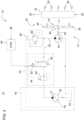
- Fig. 1 shows a simplified representation of a circuit diagram of the hydraulic operating device according to the invention according to a first exemplary embodiment.
- the hydraulic operating device 12 for a cooling fan 14 located in a commercial vehicle 10 comprises a hydraulic motor 16 and a fan unit 18 that can be driven by the hydraulic motor 16 for generating a cooling air flow 20.
- the fan unit 18 is designed as an axial fan 22, but it can be different also be a radial fan.
- the axial fan 22 has a plurality of fan blades 26 projecting along an outer circumference of a fan hub 24, the fan hub 24 being connected to an output 30 of the hydraulic motor 16 via a drive shaft 28.
- Fan unit 18 and hydraulic motor 16 combine to form the cooling fan 14.
- the cooling air flow 20 generated by the fan unit 18 passes through an intercooler 32, which serves to cool charge air that is compressed by a turbocharger 34 and supplied to a supercharged diesel engine 36.
- the operating device 12 includes a hydraulic supply formed by a hydraulic variable pump 38 for providing pressurized hydraulic fluid.
- the hydraulic variable pump 38 sucks this in from a reservoir 42.
- the hydraulic variable pump 38 is part of a (main) hydraulic system 40 of the commercial vehicle 10 and is used there to operate various vehicle and work-related functions.
- the commercial vehicle 10 is, for example, an agricultural tractor or any other commercial vehicle from the agricultural and forestry sector or the construction machinery sector.
- a control valve 44 is used to adjust a volume flow passing through the hydraulic motor 16 depending on a control signal representing a cooling requirement 46.
- the (in this case electrical) control signal is generated by means of a control unit 48, which serves to monitor a cooling requirement requested by the intercooler 32.
- control valve 44 is opened or closed depending on the control signal, which leads to a corresponding increase or decrease in the volume flow passing through the hydraulic motor 16.
- the change in the hydraulic pressure that occurs in the supply line 50 is reported back via the sensor line 52 to the pressure control input 54 of the hydraulic variable displacement pump 38, to which this responds with a corresponding increase or decrease in the delivery volume.
- a throttle element 56 designed as a constant throttle in the form of a diaphragm or nozzle in the sensor line 52 provided for load reporting, which limits hydraulic losses in the direction of the pressure control input 54 of the hydraulic variable displacement pump 38 to non-critical values.
- the throttle element 56 can also be omitted.
- a one-way or check valve 58 which is permeable in the direction of the pressure control input 54 of the hydraulic variable pump 38 is also arranged in the sensor line 52. This is located within the sensor line 52 in series with the throttle element 56.
- the one-way or check valve 58 prevents undesirable speed fluctuations of the fan unit 18 due to pressure reactions that are caused at the pressure control input 54 of the hydraulic variable pump 38 due to superimposed load reports from other hydraulic consumers.
- control valve 44 is a 2/2-way proportional valve 60, which can be electrically actuated by means of an associated solenoid 62 based on the control signal generated by the control unit 48.
- the control valve 44 is designed to be pressure-compensated.
- a pressure control valve 64 between the hydraulic variable pump 38 and the 2/2-way proportional valve 60, which compares an output-side hydraulic pressure with an input-side hydraulic pressure on the 2/2-way proportional valve 60 and sets it to a fixed differential pressure.
- the 2/2-way proportional valve 60 maintains the volume flow specified in accordance with the control signal and thus the speed of the fan unit 18 remains largely constant even in the event of load fluctuations of the hydraulic motor 16 and / or operational pressure fluctuations in the hydraulic supply.
- the pressure control valve 64 can be a structural component of the control valve 44 together with the 2/2-way proportional valve 60.
- pressure compensation can also be dispensed with; the additional pressure control valve 64 is then omitted.
- the 2/2-way proportional valve 60 is designed, for example, in such a way that, in the event of a fault in the control unit 48, it automatically assumes a fully open position and thus maintains the required cooling of the intercooler 32. Deviating from this, however, it is also possible for the 2/2-way proportional valve 60 to be biased towards a closed position, so that if the control unit 48 fails, the operation of the hydraulic motor 16 is specifically interrupted.
- a correspondingly designed 2/2-way proportional valve 60 is representative Fig. 2 reproduced.
- Fig. 2 shows a simplified representation of a circuit diagram of the hydraulic operating device according to the invention according to a second exemplary embodiment.
- this differs from that in Fig. 1 reproduced first embodiment further to the effect that instead of a one-way or check valve 58 in the sensor line 52, there is an opening in the direction of the pressure control input 54 of the hydraulic variable displacement pump 38
- Pressure relief valve 66 is arranged.
- the pressure relief valve 66 behaves like a one-way or check valve, but additionally reduces the hydraulic pressure reported back to the pressure control input 54 by an amount corresponding to its respective switching threshold. This ultimately gives the hydraulic variable pump 38 the illusion of a reduced hydraulic load, which, with a suitable design of the hydraulic motor 16, allows an additional improvement in energy efficiency to be achieved without impairing the cooling performance to be provided by the fan unit 18.
Landscapes
- Engineering & Computer Science (AREA)
- Chemical & Material Sciences (AREA)
- Combustion & Propulsion (AREA)
- Mechanical Engineering (AREA)
- General Engineering & Computer Science (AREA)
- Auxiliary Drives, Propulsion Controls, And Safety Devices (AREA)
- Fluid-Pressure Circuits (AREA)
Abstract
Description
- Die Erfindung betrifft eine hydraulische Betriebseinrichtung für einen Kühllüfter eines Nutzfahrzeugs.
- Eine derartige Betriebseinrichtung findet unter anderem in landwirtschaftlichen Traktoren des Herstellers John Deere zur Kühlung von mittels eines Turboladers verdichteter sowie einem aufgeladenen Dieselmotor zuzuführender Ladeluft Verwendung. Die insofern bekannte Betriebseinrichtung weist einen hydraulischen Motor auf, der ein Lüfterrad zur Erzeugung eines durch einen Ladeluftkühler hindurchtretenden Axialluftstroms antreibt. Der Betrieb des hydraulischen Motors erfolgt mittels einer eigens hierfür vorgesehenen Hydraulikpumpe mit konstantem Fördervolumen. Um in einem solchen Fall die Drehzahl des Lüfterrads und damit die Intensität des Axialluftstroms dem jeweiligen Kühlbedarf anpassen zu können, ist dem hydraulischen Motor ein Bypass-Ventil in Gestalt eines elektrisch steuerbaren Druckregelventils parallel geschaltet. Die so geschaffene Anordnung ermöglicht eine flexible Unterbringung des Ladeluftkühlers innerhalb des landwirtschaftlichen Traktors und damit eine verbesserte Nutzung des insofern zur Verfügung stehenden Bauraums.
- Daneben sind landwirtschaftliche Traktoren üblicherweise auch mit einem (Haupt-) Hydrauliksystem ausgestattet, das dem Betrieb diverser fahrzeug- bzw. arbeitsbezogener Funktionen dient. Das Hydrauliksystem umfasst seinerseits eine aus einem Reservoir für Hydraulikflüssigkeit gespeiste Hydraulikpumpe in Gestalt einer hydraulischen Verstellpumpe. Die hydraulische Verstellpumpe weist einen Drucksteuereingang auf, der es ermöglicht, das Fördervolumen nach Maßgabe eines rückgemeldeten Hydraulikdrucks wunschgemäß einzustellen.
- Das Vorhandensein zweier Hydraulikpumpen führt naturgemäß zu einem erhöhten Bauraumbedarf innerhalb des landwirtschaftlichen Traktors. Auch ergeben sich aus der aus Kostengründen üblichen Verwendung einer Hydraulikpumpe mit konstantem Fördervolumen zwangsläufig Kompromisse hinsichtlich der Energieeffizienz, was insbesondere für den Fall eines Teillastbetriebs des hydraulischen Motors zutrifft.
- Aufgabe der vorliegenden Erfindung ist es daher, eine hydraulische Betriebseinrichtung für einen Kühllüfter eines Nutzfahrzeugs hinsichtlich einer Optimierung des benötigten Bauraums sowie der Energieeffizienz auszubilden.
- Diese Aufgabe wird durch eine hydraulische Betriebseinrichtung mit den Merkmalen des Patentanspruchs 1 gelöst.
- Die hydraulische Betriebseinrichtung für einen Kühllüfter eines Nutzfahrzeugs umfasst einen hydraulischen Motor sowie ein von dem hydraulischen Motor antreibbares Lüfteraggregat zur Erzeugung eines Kühlluftstroms, eine nach Maßgabe einer Druckrückmeldung bezüglich ihres Fördervolumens verstellbare Hydraulikversorgung zur Bereitstellung von unter Druck stehender Hydraulikflüssigkeit, und ein Steuerventil zur Einstellung eines durch den hydraulischen Motor hindurchtretenden Volumenstroms in Abhängigkeit eines eine Kühlanforderung repräsentierenden Steuersignals, wobei eine in einer Versorgungsleitung zwischen Steuerventil und hydraulischem Motor abgezweigte Sensorleitung zu einem zur Druckrückmeldung vorgesehenen Drucksteuereingang der Hydraulikversorgung führt.
- Zur Anpassung der Drehzahl des hydraulischen Motors und damit der Kühlleistung des Lüfteraggregats wird das Steuerventil in Abhängigkeit des Steuersignals geöffnet oder geschlossen, was zu einer entsprechenden Zu- oder Abnahme des durch den hydraulischen Motor hindurchtretenden Volumenstroms führt. Die dabei in der Versorgungsleitung auftretende Änderung des Hydraulikdrucks wird über die Sensorleitung an den Drucksteuereingang der Hydraulikversorgung rückgemeldet, worauf diese mit einer entsprechenden Erhöhung oder Verringerung des Fördervolumens reagiert.
- Dies führt zu einem dem tatsächlichen Kühlbedarf angepassten und damit besonders effizienten Betrieb des Lüfteraggregats.
- Der mittels des Lüfteraggregats erzeugte Kühlluftstrom tritt beispielsweise durch einen Ladeluftkühler hindurch, der der Kühlung von mittels eines Turboladers verdichteter sowie einem aufgeladenen Dieselmotor zuzuführender Ladeluft dient. Das Lüfteraggregat ist hierbei als Axial- oder Radiallüfter ausgebildet.
- In der zur Lastmeldung vorgesehenen Sensorleitung kann sich ein als Konstantdrossel ausgebildetes Drosselelement in Gestalt einer Blende oder Düse befinden, das hydraulische Verluste in Richtung des Drucksteuereingangs der Hydraulikversorgung auf unkritische Werte begrenzt. Je nach konkreter Ausbildung des Hydrauliksystems kann das Drosselelement jedoch auch entfallen.
- Grundsätzlich bietet sich ein Einsatz der erfindungsgemäßen Betriebseinrichtung bei all jenen Nutzfahrzeugen an, die mit einem Hydrauliksystem zum Betrieb diverser fahrzeug- bzw. arbeitsbezogener Funktionen ausgestattetet sind und die zu diesem Zweck eine (beispielsweise durch eine hydraulische Verstellpumpe gebildete) Hydraulikversorgung aufweisen. Dies trifft nicht nur auf landwirtschaftliche Traktoren zu, sondern auch auf die meisten anderen Nutzfahrzeuge aus dem land- und forstwirtschaftlichen Bereich oder dem Baumaschinenbereich. Die Notwendigkeit einer separaten Hydraulikpumpe erübrigt sich unter solchen Umständen.
- Vorteilhafte Weiterbildungen der erfindungsgemäßen Betriebseinrichtung gehen aus den Unteransprüchen hervor.
- Vorzugsweise handelt es sich bei dem Steuerventil um ein 2/2-Wege-Proportionalventil. Das 2/2-Wege-Proportionalventil kann elektrisch oder druckbetätigbar ausgeführt sein. Dementsprechend kann auf Grundlage des Steuersignals eine elektrische Ventilbetätigung mittels eines dem 2/2-Wege-Proportionalventil zugehörigen Solenoids oder Schrittmotors, aber auch eine hydraulische Ventilbetätigung durch Einsteuerung eines Pilotdrucks in einen Drucksteuereingang des 2/2-Wege-Proportionalventils vorgesehen sein. Die Erzeugung des Pilotdrucks erfolgt mittels eines in Abhängigkeit des Steuersignals elektrisch betätigbaren Pilotventils, das sich zwischen der Hydraulikversorgung und dem Drucksteuereingang des 2/2-Wege-Proportionalventils befindet.
- Des Weiteren besteht die Möglichkeit, dass das Steuerventil druckkompensiert ausgebildet ist. Aufgrund der Druckkompensation hält das Steuerventil den nach Maßgabe des Steuersignals vorgegebenen Volumenstrom und damit die Drehzahl des Lüfteraggregats auch im Falle von Lastschwankungen des hydraulischen Motors und/oder von betriebsbedingten Druckschwankungen der Hydraulikversorgung weitgehend konstant.
- In der Sensorleitung kann ein in Richtung des Drucksteuereingangs der Hydraulikversorgung durchlässiges Einweg- oder Rückschlagventil angeordnet sein. Dieses unterbindet unerwünschte Drehzahlschwankungen des Lüfteraggregats aufgrund von Druckrückwirkungen, die am Drucksteuereingang der Hydraulikversorgung aufgrund von überlagerten Lastmeldungen weiterer hydraulischer Verbraucher verursacht werden.
- Anstelle eines Einweg- oder Rückschlagventils kann in der Sensorleitung auch ein in Richtung des Drucksteuereingangs der Hydraulikversorgung öffnendes Druckbegrenzungsventil angeordnet sein. Hinsichtlich der Vermeidung unerwünschter Druckrückwirkungen über die Sensorleitung verhält sich das Druckbegrenzungsventil wie ein Einweg- oder Rückschlagventil, verringert jedoch zusätzlich den an den Drucksteuereingang der Hydraulikversorgung rückgemeldeten Hydraulikdruck um einen seiner jeweiligen Schaltschwelle entsprechenden Betrag. Dies täuscht der Hydraulikversorgung letztlich eine verringerte hydraulische Last vor, die es bei geeigneter Auslegung des hydraulischen Motors erlaubt, eine zusätzliche Verbesserung der Energieeffizienz zu erzielen, ohne die mittels des Lüfteraggregats zu erbringende Kühlleistung zu beeinträchtigen.
- Die erfindungsgemäße hydraulische Betriebseinrichtung für einen Kühllüfter eines Nutzfahrzeugs wird im Folgenden anhand der beigefügten Zeichnungen näher beschrieben. Dabei beziehen sich identische Bezugszeichen auf übereinstimmende oder bezüglich ihrer Funktion vergleichbare Komponenten. Es zeigen:
- Fig. 1
- ein schematisch dargestelltes erstes Ausführungsbeispiel der erfindungsgemäßen hydraulischen Betriebseinrichtung, und
- Fig. 2
- ein schematisch dargestelltes zweites Ausführungsbeispiel der erfindungsgemäßen hydraulischen Betriebseinrichtung.
-
Fig. 1 zeigt in einer vereinfachten Darstellung ein Schaltschema der erfindungsgemäßen hydraulischen Betriebseinrichtung gemäß einem ersten Ausführungsbeispiel. - Die in einem Nutzfahrzeug 10 befindliche hydraulische Betriebseinrichtung 12 für einen Kühllüfter 14 umfasst einen hydraulischen Motor 16 sowie ein von dem hydraulischen Motor 16 antreibbares Lüfteraggregat 18 zur Erzeugung eines Kühlluftstroms 20. Beispielsgemäß ist das Lüfteraggregat 18 als Axiallüfter 22 ausgebildet, abweichend davon kann es sich jedoch auch um einen Radiallüfter handeln. Der Axiallüfter 22 weist eine Vielzahl von entlang eines Außenumfangs einer Lüfternabe 24 hervorspringenden Lüfterflügeln 26 auf, wobei die Lüfternabe 24 über eine Antriebswelle 28 mit einem Abtrieb 30 des hydraulischen Motors 16 in Verbindung steht. Lüfteraggregat 18 und hydraulischer Motor 16 bilden hierbei in Kombination miteinander den Kühllüfter 14.
- Der mittels des Lüfteraggregats 18 erzeugte Kühlluftstrom 20 tritt vorliegend durch einen Ladeluftkühler 32 hindurch, der der Kühlung von mittels eines Turboladers 34 verdichteter sowie einem aufgeladenen Dieselmotor 36 zuzuführender Ladeluft dient.
- Des Weiteren umfasst die Betriebseinrichtung 12 eine durch eine hydraulische Verstellpumpe 38 gebildete Hydraulikversorgung zur Bereitstellung von unter Druck stehender Hydraulikflüssigkeit. Diese saugt die hydraulische Verstellpumpe 38 aus einem Reservoir 42 an.
- Die hydraulische Verstellpumpe 38 ist Bestandteil eines (Haupt-) Hydrauliksystems 40 des Nutzfahrzeugs 10 und dient dort dem Betrieb diverser fahrzeug- und arbeitsbezogener Funktionen. Bei dem Nutzfahrzeug 10 handelt es sich zum Beispiel um einen landwirtschaftlichen Traktor oder ein beliebiges anderes Nutzfahrzeug aus dem land- und forstwirtschaftlichen Bereich oder dem Baumaschinenbereich.
- Ein Steuerventil 44 dient zur Einstellung eines durch den hydraulischen Motor 16 hindurchtretenden Volumenstroms in Abhängigkeit eines eine Kühlanforderung 46 repräsentierenden Steuersignals. Die Erzeugung des (vorliegend elektrischen) Steuersignals erfolgt mittels einer Kontrolleinheit 48, die der Überwachung eines seitens des Ladeluftkühlers 32 angeforderten Kühlbedarfs dient.
- Weiterhin führt eine in einer Versorgungsleitung 50 zwischen Steuerventil 44 und hydraulischem Motor 16 abgezweigte Sensorleitung 52 zu einem der Druckrückmeldung dienenden Drucksteuereingang 54 der hydraulischen Verstellpumpe 38.
- Zur Anpassung der Drehzahl des hydraulischen Motors 16 und damit der Kühlleistung des Lüfteraggregats 18 wird das Steuerventil 44 in Abhängigkeit des Steuersignals geöffnet oder geschlossen, was zu einer entsprechenden Zu- oder Abnahme des durch den hydraulischen Motor 16 hindurchtretenden Volumenstroms führt. Die dabei in der Versorgungsleitung 50 auftretende Änderung des Hydraulikdrucks wird über die Sensorleitung 52 an den Drucksteuereingang 54 der hydraulischen Verstellpumpe 38 rückgemeldet, worauf diese mit einer entsprechenden Erhöhung oder Verringerung des Fördervolumens reagiert.
- Gemäß
Fig. 1 befindet sich in der zur Lastmeldung vorgesehenen Sensorleitung 52 ein als Konstantdrossel ausgebildetes Drosselelement 56 in Gestalt einer Blende oder Düse, das hydraulische Verluste in Richtung des Drucksteuereingangs 54 der hydraulischen Verstellpumpe 38 auf unkritische Werte begrenzt. Je nach konkreter Ausbildung des Hydrauliksystems 40 kann das Drosselelement 56 jedoch auch entfallen. - In der Sensorleitung 52 ist ferner ein in Richtung des Drucksteuereingangs 54 der hydraulischen Verstellpumpe 38 durchlässiges Einweg- oder Rückschlagventil 58 angeordnet. Dieses liegt innerhalb der Sensorleitung 52 in Serie zum Drosselelement 56. Das Einweg- oder Rückschlagventil 58 unterbindet unerwünschte Drehzahlschwankungen des Lüfteraggregats 18 aufgrund von Druckrückwirkungen, die am Drucksteuereingang 54 der hydraulischen Verstellpumpe 38 aufgrund von überlagerten Lastmeldungen weiterer hydraulischer Verbraucher verursacht werden.
- Beispielsgemäß handelt es sich bei dem Steuerventil 44 um ein 2/2-Wege-Proportionalventil 60, das sich mittels eines zugehörigen Solenoids 62 auf Grundlage des von der Kontrolleinheit 48 erzeugten Steuersignals elektrisch betätigen lässt.
- Das Steuerventil 44 ist druckkompensiert ausgebildet. Hierzu befindet sich zwischen hydraulischer Verstellpumpe 38 und 2/2-Wege-Proportionalventil 60 ein Druckregelventil 64, das einen ausgangsseitigen Hydraulikdruck mit einem eingangsseitigen Hydraulikdruck am 2/2-Wege-Proportionalventil 60 vergleicht und auf einen festen Differenzdruck einstellt. Auf diese Weise hält das 2/2-Wege-Proportionalventil 60 den nach Maßgabe des Steuersignals vorgegebenen Volumenstrom und damit die Drehzahl des Lüfteraggregats 18 auch im Falle von Lastschwankungen des hydraulischen Motors 16 und/oder von betriebsbedingten Druckschwankungen der Hydraulikversorgung weitgehend konstant. Das Druckregelventil 64 kann gemeinsam mit dem 2/2-Wege-Proportionalventil 60 baulicher Bestandteil des Steuerventils 44 sein.
- Bei geringeren Anforderungen an die Konstanz der Kühlleistung kann auch auf eine Druckkompensation verzichtet werden, das zusätzliche Druckregelventil 64 entfällt dann.
- Zur Verwirklichung eines ausfallsicheren Betriebs ist das 2/2-Wege-Proportionalventil 60 beispielsgemäß derart ausgebildet, dass dieses bei einem Fehler der Kontrolleinheit 48 von selbst eine vollständig geöffnete Stellung einnimmt und so die erforderliche Kühlung des Ladeluftkühlers 32 aufrechterhält. Davon abweichend ist es jedoch auch möglich, dass das 2/2-Wege-Proportionalventil 60 in Richtung einer geschlossenen Stellung vorgespannt ist, sodass bei einem Ausfall der Kontrolleinheit 48 der Betrieb des hydraulischen Motors 16 gezielt unterbrochen wird. Ein entsprechend ausgebildetes 2/2-Wege-Proportionalventil 60 ist repräsentativ in
Fig. 2 wiedergegeben. -
Fig. 2 zeigt in einer vereinfachten Darstellung ein Schaltschema der erfindungsgemäßen hydraulischen Betriebseinrichtung gemäß einem zweiten Ausführungsbeispiel. Dieses unterscheidet sich neben der bereits erwähnten abweichenden Ausbildung des 2/2-Wege-Proportionalventils 60 gegenüber dem inFig. 1 wiedergegebenen ersten Ausführungsbeispiel ferner dahingehend, dass anstelle eines Einweg- oder Rückschlagventils 58 in der Sensorleitung 52 ein in Richtung des Drucksteuereingangs 54 der hydraulischen Verstellpumpe 38 öffnendes Druckbegrenzungsventil 66 angeordnet ist. Hinsichtlich der Vermeidung unerwünschter Druckrückwirkungen über die Sensorleitung 52 verhält sich das Druckbegrenzungsventil 66 wie ein Einweg- oder Rückschlagventil, verringert jedoch zusätzlich den an den Drucksteuereingang 54 rückgemeldeten Hydraulikdruck um einen seiner jeweiligen Schaltschwelle entsprechenden Betrag. Dies täuscht der hydraulischen Verstellpumpe 38 letztlich eine verringerte hydraulische Last vor, die es bei geeigneter Auslegung des hydraulischen Motors 16 erlaubt, eine zusätzliche Verbesserung der Energieeffizienz zu erzielen, ohne die mittels des Lüfteraggregats 18 zu erbringende Kühlleistung zu beeinträchtigen.
Claims (5)
- Hydraulische Betriebseinrichtung für einen Kühllüfter eines Nutzfahrzeugs, umfassend einen hydraulischen Motor (16) sowie ein von dem hydraulischen Motor (16) antreibbares Lüfteraggregat (18) zur Erzeugung eines Kühlluftstroms (20), eine nach Maßgabe einer Druckrückmeldung bezüglich ihres Fördervolumens verstellbare Hydraulikversorgung (38) zur Bereitstellung von unter Druck stehender Hydraulikflüssigkeit, und ein Steuerventil (44) zur Einstellung eines durch den hydraulischen Motor (16) hindurchtretenden Volumenstroms in Abhängigkeit eines eine Kühlanforderung (46) repräsentierenden Steuersignals, wobei eine in einer Versorgungsleitung (50) zwischen Steuerventil (44) und hydraulischem Motor (16) abgezweigte Sensorleitung (52) zu einem Drucksteuereingang (54) der Hydraulikversorgung (38) führt.
- Betriebseinrichtung nach Anspruch 1, dadurch gekennzeichnet, dass es sich bei dem Steuerventil (44) um ein 2/2-Wege-Proportionalventil (60) handelt.
- Betriebseinrichtung nach Anspruch 1 oder 2, dadurch gekennzeichnet, dass das Steuerventil (44) druckkompensiert ausgebildet ist.
- Betriebseinrichtung nach wenigstens einem der vorhergehenden Ansprüche, dadurch gekennzeichnet, dass in der Sensorleitung (52) ein in Richtung des Drucksteuereingangs (54) der Hydraulikversorgung (38) durchlässiges Einweg- oder Rückschlagventil (58) angeordnet ist.
- Betriebseinrichtung nach wenigstens einem der vorhergehenden Ansprüche, dadurch gekennzeichnet, dass in der Sensorleitung (52) ein in Richtung des Drucksteuereingangs (54) der Hydraulikversorgung (38) öffnendes Druckbegrenzungsventil (66) angeordnet ist.
Applications Claiming Priority (1)
| Application Number | Priority Date | Filing Date | Title |
|---|---|---|---|
| DE102022110886.4A DE102022110886A1 (de) | 2022-05-03 | 2022-05-03 | Hydraulische Betriebseinrichtung für einen Kühllüfter eines Nutzfahrzeugs |
Publications (2)
| Publication Number | Publication Date |
|---|---|
| EP4273377A1 true EP4273377A1 (de) | 2023-11-08 |
| EP4273377B1 EP4273377B1 (de) | 2025-08-13 |
Family
ID=86051825
Family Applications (1)
| Application Number | Title | Priority Date | Filing Date |
|---|---|---|---|
| EP23168158.6A Active EP4273377B1 (de) | 2022-05-03 | 2023-04-17 | Hydraulische betriebseinrichtung für einen kühllüfter eines nutzfahrzeugs |
Country Status (3)
| Country | Link |
|---|---|
| US (1) | US12221916B2 (de) |
| EP (1) | EP4273377B1 (de) |
| DE (1) | DE102022110886A1 (de) |
Citations (4)
| Publication number | Priority date | Publication date | Assignee | Title |
|---|---|---|---|---|
| US6314729B1 (en) * | 1998-07-23 | 2001-11-13 | Sauer-Danfoss Inc. | Hydraulic fan drive system having a non-dedicated flow source |
| US20060196179A1 (en) * | 2005-03-01 | 2006-09-07 | Arun Kesavan | Load-sensing integrated brake and fan hydraulic system |
| US8863508B2 (en) * | 2011-06-28 | 2014-10-21 | Caterpillar Inc. | Hydraulic circuit having energy storage and reuse |
| US20220056833A1 (en) * | 2018-09-21 | 2022-02-24 | Hitachi Construction Machinery Co., Ltd. | Hydraulic Drive Fan Control Device |
Family Cites Families (4)
| Publication number | Priority date | Publication date | Assignee | Title |
|---|---|---|---|---|
| US6848255B2 (en) * | 2002-12-18 | 2005-02-01 | Caterpillar Inc | Hydraulic fan drive system |
| DE102007058534B4 (de) | 2007-12-06 | 2016-01-21 | Deere & Company | Kühlanordnung mit hydraulisch angetriebenen Lüftern |
| DE102011113542A1 (de) * | 2011-09-15 | 2013-03-21 | Robert Bosch Gmbh | Hydraulischer Lüfterantrieb für einen Verbrennungsmotor |
| US9127697B1 (en) * | 2012-08-02 | 2015-09-08 | Sauer-Danfoss Inc. | Dynamically stable pressure control system |
-
2022
- 2022-05-03 DE DE102022110886.4A patent/DE102022110886A1/de active Pending
-
2023
- 2023-04-17 EP EP23168158.6A patent/EP4273377B1/de active Active
- 2023-04-26 US US18/307,185 patent/US12221916B2/en active Active
Patent Citations (4)
| Publication number | Priority date | Publication date | Assignee | Title |
|---|---|---|---|---|
| US6314729B1 (en) * | 1998-07-23 | 2001-11-13 | Sauer-Danfoss Inc. | Hydraulic fan drive system having a non-dedicated flow source |
| US20060196179A1 (en) * | 2005-03-01 | 2006-09-07 | Arun Kesavan | Load-sensing integrated brake and fan hydraulic system |
| US8863508B2 (en) * | 2011-06-28 | 2014-10-21 | Caterpillar Inc. | Hydraulic circuit having energy storage and reuse |
| US20220056833A1 (en) * | 2018-09-21 | 2022-02-24 | Hitachi Construction Machinery Co., Ltd. | Hydraulic Drive Fan Control Device |
Also Published As
| Publication number | Publication date |
|---|---|
| EP4273377B1 (de) | 2025-08-13 |
| DE102022110886A1 (de) | 2023-11-09 |
| US20230358160A1 (en) | 2023-11-09 |
| US12221916B2 (en) | 2025-02-11 |
Similar Documents
| Publication | Publication Date | Title |
|---|---|---|
| DE102018207158A1 (de) | Hydraulische Steueranordnung für eine Anordnung mobiler Arbeitsmaschinen und Anordnung mobiler Arbeitsmaschinen | |
| WO2006102948A1 (de) | Kraftfahrzeug-hydraulikpumpe | |
| DE3934641A1 (de) | Hydraulische schaltung zur begrenzung des drehmoments eines hydrostatischen hydromotors | |
| EP1828642B1 (de) | Hydrostatischer antrieb mit drehzahlbegrenzung | |
| DE102008054880A1 (de) | Hydrauliksystem | |
| EP1989450A1 (de) | Hydraulische steueranordnung | |
| EP3012463B1 (de) | Hydraulikaggregat | |
| EP4105496B1 (de) | Hydraulikaggregat zur versorgung hydraulisch antreibbarer rettungsgeräte | |
| DE102013001928A1 (de) | Kraftfahrzeuggetriebevorrichtung mit einem Hydrauliksystem | |
| EP2049800B1 (de) | Förderpumpe | |
| EP4407156A2 (de) | Hydrauliksystem für eine landwirtschaftliche arbeitsmaschine | |
| EP4273377B1 (de) | Hydraulische betriebseinrichtung für einen kühllüfter eines nutzfahrzeugs | |
| EP2280197B1 (de) | Hydrostatischer Mehrmotorenantrieb | |
| DE19600660C2 (de) | Hydraulisch reversierbare Verstellpropeller-Einheit | |
| DE19509869B4 (de) | Steuer- und Regelsystem für ein automotives hydrostatisches Getriebe | |
| WO1999015792A1 (de) | Regeleinrichtung für eine verstellbare hydropumpe mit mehreren verbrauchern | |
| DE102020116290A1 (de) | Aktives Fahrwerksystem für ein Kraftfahrzeug mit zwei Fahrzeugachsen | |
| DE102007051185A1 (de) | Hydrostatischer Antrieb | |
| DE102006039698B3 (de) | Förderpumpe | |
| DE102023202657A1 (de) | Verfahren zur ansteuerung eines hydrostatischen antriebs | |
| EP1426209A1 (de) | Hydraulisches Stabilisierungssystem | |
| WO2022207416A9 (de) | Vorrichtung zum regeln einer hydraulikpumpe oder eines hydraulikmotors | |
| DE102007049413B3 (de) | Anordnung zur Veränderung des Volumenstroms einer Verdrängermaschine | |
| DE202006015508U1 (de) | Förderpumpe | |
| DE102021124436B3 (de) | Baumaschine und Verfahren zum Antreiben eines Arbeitsgerätes |
Legal Events
| Date | Code | Title | Description |
|---|---|---|---|
| PUAI | Public reference made under article 153(3) epc to a published international application that has entered the european phase |
Free format text: ORIGINAL CODE: 0009012 |
|
| STAA | Information on the status of an ep patent application or granted ep patent |
Free format text: STATUS: THE APPLICATION HAS BEEN PUBLISHED |
|
| AK | Designated contracting states |
Kind code of ref document: A1 Designated state(s): AL AT BE BG CH CY CZ DE DK EE ES FI FR GB GR HR HU IE IS IT LI LT LU LV MC ME MK MT NL NO PL PT RO RS SE SI SK SM TR |
|
| STAA | Information on the status of an ep patent application or granted ep patent |
Free format text: STATUS: REQUEST FOR EXAMINATION WAS MADE |
|
| 17P | Request for examination filed |
Effective date: 20240508 |
|
| RBV | Designated contracting states (corrected) |
Designated state(s): AL AT BE BG CH CY CZ DE DK EE ES FI FR GB GR HR HU IE IS IT LI LT LU LV MC ME MK MT NL NO PL PT RO RS SE SI SK SM TR |
|
| GRAP | Despatch of communication of intention to grant a patent |
Free format text: ORIGINAL CODE: EPIDOSNIGR1 |
|
| STAA | Information on the status of an ep patent application or granted ep patent |
Free format text: STATUS: GRANT OF PATENT IS INTENDED |
|
| INTG | Intention to grant announced |
Effective date: 20250423 |
|
| GRAS | Grant fee paid |
Free format text: ORIGINAL CODE: EPIDOSNIGR3 |
|
| GRAA | (expected) grant |
Free format text: ORIGINAL CODE: 0009210 |
|
| STAA | Information on the status of an ep patent application or granted ep patent |
Free format text: STATUS: THE PATENT HAS BEEN GRANTED |
|
| AK | Designated contracting states |
Kind code of ref document: B1 Designated state(s): AL AT BE BG CH CY CZ DE DK EE ES FI FR GB GR HR HU IE IS IT LI LT LU LV MC ME MK MT NL NO PL PT RO RS SE SI SK SM TR |
|
| REG | Reference to a national code |
Ref country code: GB Ref legal event code: FG4D Free format text: NOT ENGLISH |
|
| REG | Reference to a national code |
Ref country code: CH Ref legal event code: EP |
|
| REG | Reference to a national code |
Ref country code: DE Ref legal event code: R096 Ref document number: 502023001550 Country of ref document: DE |
|
| REG | Reference to a national code |
Ref country code: IE Ref legal event code: FG4D Free format text: LANGUAGE OF EP DOCUMENT: GERMAN |
|
| REG | Reference to a national code |
Ref country code: NL Ref legal event code: MP Effective date: 20250813 |
|
| PG25 | Lapsed in a contracting state [announced via postgrant information from national office to epo] |
Ref country code: IS Free format text: LAPSE BECAUSE OF FAILURE TO SUBMIT A TRANSLATION OF THE DESCRIPTION OR TO PAY THE FEE WITHIN THE PRESCRIBED TIME-LIMIT Effective date: 20251213 |
|
| PG25 | Lapsed in a contracting state [announced via postgrant information from national office to epo] |
Ref country code: NO Free format text: LAPSE BECAUSE OF FAILURE TO SUBMIT A TRANSLATION OF THE DESCRIPTION OR TO PAY THE FEE WITHIN THE PRESCRIBED TIME-LIMIT Effective date: 20251113 |
|
| REG | Reference to a national code |
Ref country code: LT Ref legal event code: MG9D |
|
| PG25 | Lapsed in a contracting state [announced via postgrant information from national office to epo] |
Ref country code: PT Free format text: LAPSE BECAUSE OF FAILURE TO SUBMIT A TRANSLATION OF THE DESCRIPTION OR TO PAY THE FEE WITHIN THE PRESCRIBED TIME-LIMIT Effective date: 20251215 |
|
| PG25 | Lapsed in a contracting state [announced via postgrant information from national office to epo] |
Ref country code: FI Free format text: LAPSE BECAUSE OF FAILURE TO SUBMIT A TRANSLATION OF THE DESCRIPTION OR TO PAY THE FEE WITHIN THE PRESCRIBED TIME-LIMIT Effective date: 20250813 |
|
| PG25 | Lapsed in a contracting state [announced via postgrant information from national office to epo] |
Ref country code: HR Free format text: LAPSE BECAUSE OF FAILURE TO SUBMIT A TRANSLATION OF THE DESCRIPTION OR TO PAY THE FEE WITHIN THE PRESCRIBED TIME-LIMIT Effective date: 20250813 Ref country code: NL Free format text: LAPSE BECAUSE OF FAILURE TO SUBMIT A TRANSLATION OF THE DESCRIPTION OR TO PAY THE FEE WITHIN THE PRESCRIBED TIME-LIMIT Effective date: 20250813 |
|
| PG25 | Lapsed in a contracting state [announced via postgrant information from national office to epo] |
Ref country code: GR Free format text: LAPSE BECAUSE OF FAILURE TO SUBMIT A TRANSLATION OF THE DESCRIPTION OR TO PAY THE FEE WITHIN THE PRESCRIBED TIME-LIMIT Effective date: 20251114 |
|
| PG25 | Lapsed in a contracting state [announced via postgrant information from national office to epo] |
Ref country code: SE Free format text: LAPSE BECAUSE OF FAILURE TO SUBMIT A TRANSLATION OF THE DESCRIPTION OR TO PAY THE FEE WITHIN THE PRESCRIBED TIME-LIMIT Effective date: 20250813 |
|
| PG25 | Lapsed in a contracting state [announced via postgrant information from national office to epo] |
Ref country code: LV Free format text: LAPSE BECAUSE OF FAILURE TO SUBMIT A TRANSLATION OF THE DESCRIPTION OR TO PAY THE FEE WITHIN THE PRESCRIBED TIME-LIMIT Effective date: 20250813 |
|
| PG25 | Lapsed in a contracting state [announced via postgrant information from national office to epo] |
Ref country code: BG Free format text: LAPSE BECAUSE OF FAILURE TO SUBMIT A TRANSLATION OF THE DESCRIPTION OR TO PAY THE FEE WITHIN THE PRESCRIBED TIME-LIMIT Effective date: 20250813 Ref country code: PL Free format text: LAPSE BECAUSE OF FAILURE TO SUBMIT A TRANSLATION OF THE DESCRIPTION OR TO PAY THE FEE WITHIN THE PRESCRIBED TIME-LIMIT Effective date: 20250813 |
|
| PG25 | Lapsed in a contracting state [announced via postgrant information from national office to epo] |
Ref country code: RS Free format text: LAPSE BECAUSE OF FAILURE TO SUBMIT A TRANSLATION OF THE DESCRIPTION OR TO PAY THE FEE WITHIN THE PRESCRIBED TIME-LIMIT Effective date: 20251113 |
|
| PG25 | Lapsed in a contracting state [announced via postgrant information from national office to epo] |
Ref country code: ES Free format text: LAPSE BECAUSE OF FAILURE TO SUBMIT A TRANSLATION OF THE DESCRIPTION OR TO PAY THE FEE WITHIN THE PRESCRIBED TIME-LIMIT Effective date: 20250813 |
|
| PG25 | Lapsed in a contracting state [announced via postgrant information from national office to epo] |
Ref country code: SM Free format text: LAPSE BECAUSE OF FAILURE TO SUBMIT A TRANSLATION OF THE DESCRIPTION OR TO PAY THE FEE WITHIN THE PRESCRIBED TIME-LIMIT Effective date: 20250813 |
|
| PG25 | Lapsed in a contracting state [announced via postgrant information from national office to epo] |
Ref country code: DK Free format text: LAPSE BECAUSE OF FAILURE TO SUBMIT A TRANSLATION OF THE DESCRIPTION OR TO PAY THE FEE WITHIN THE PRESCRIBED TIME-LIMIT Effective date: 20250813 |
|
| PG25 | Lapsed in a contracting state [announced via postgrant information from national office to epo] |
Ref country code: CZ Free format text: LAPSE BECAUSE OF FAILURE TO SUBMIT A TRANSLATION OF THE DESCRIPTION OR TO PAY THE FEE WITHIN THE PRESCRIBED TIME-LIMIT Effective date: 20250813 |
|
| PG25 | Lapsed in a contracting state [announced via postgrant information from national office to epo] |
Ref country code: EE Free format text: LAPSE BECAUSE OF FAILURE TO SUBMIT A TRANSLATION OF THE DESCRIPTION OR TO PAY THE FEE WITHIN THE PRESCRIBED TIME-LIMIT Effective date: 20250813 Ref country code: SK Free format text: LAPSE BECAUSE OF FAILURE TO SUBMIT A TRANSLATION OF THE DESCRIPTION OR TO PAY THE FEE WITHIN THE PRESCRIBED TIME-LIMIT Effective date: 20250813 |