EP4272912A2 - Faltmaschine - Google Patents
Faltmaschine Download PDFInfo
- Publication number
- EP4272912A2 EP4272912A2 EP23199190.2A EP23199190A EP4272912A2 EP 4272912 A2 EP4272912 A2 EP 4272912A2 EP 23199190 A EP23199190 A EP 23199190A EP 4272912 A2 EP4272912 A2 EP 4272912A2
- Authority
- EP
- European Patent Office
- Prior art keywords
- handle
- blade
- locking
- pin
- latch
- Prior art date
- Legal status (The legal status is an assumption and is not a legal conclusion. Google has not performed a legal analysis and makes no representation as to the accuracy of the status listed.)
- Pending
Links
Images


Classifications
-
- B—PERFORMING OPERATIONS; TRANSPORTING
- B26—HAND CUTTING TOOLS; CUTTING; SEVERING
- B26B—HAND-HELD CUTTING TOOLS NOT OTHERWISE PROVIDED FOR
- B26B1/00—Hand knives with adjustable blade; Pocket knives
- B26B1/02—Hand knives with adjustable blade; Pocket knives with pivoted blade
- B26B1/04—Hand knives with adjustable blade; Pocket knives with pivoted blade lockable in adjusted position
- B26B1/046—Hand knives with adjustable blade; Pocket knives with pivoted blade lockable in adjusted position with a locking member acting in axial direction parallel to the pivot axis of the blade
-
- B—PERFORMING OPERATIONS; TRANSPORTING
- B26—HAND CUTTING TOOLS; CUTTING; SEVERING
- B26B—HAND-HELD CUTTING TOOLS NOT OTHERWISE PROVIDED FOR
- B26B1/00—Hand knives with adjustable blade; Pocket knives
- B26B1/02—Hand knives with adjustable blade; Pocket knives with pivoted blade
- B26B1/04—Hand knives with adjustable blade; Pocket knives with pivoted blade lockable in adjusted position
-
- B—PERFORMING OPERATIONS; TRANSPORTING
- B26—HAND CUTTING TOOLS; CUTTING; SEVERING
- B26B—HAND-HELD CUTTING TOOLS NOT OTHERWISE PROVIDED FOR
- B26B1/00—Hand knives with adjustable blade; Pocket knives
- B26B1/10—Handles
-
- B—PERFORMING OPERATIONS; TRANSPORTING
- B26—HAND CUTTING TOOLS; CUTTING; SEVERING
- B26B—HAND-HELD CUTTING TOOLS NOT OTHERWISE PROVIDED FOR
- B26B11/00—Hand knives combined with other implements, e.g. with corkscrew, with scissors, with writing implement
- B26B11/006—Several functions combined in the blade
-
- B—PERFORMING OPERATIONS; TRANSPORTING
- B26—HAND CUTTING TOOLS; CUTTING; SEVERING
- B26B—HAND-HELD CUTTING TOOLS NOT OTHERWISE PROVIDED FOR
- B26B9/00—Blades for hand knives
-
- B—PERFORMING OPERATIONS; TRANSPORTING
- B26—HAND CUTTING TOOLS; CUTTING; SEVERING
- B26B—HAND-HELD CUTTING TOOLS NOT OTHERWISE PROVIDED FOR
- B26B9/00—Blades for hand knives
- B26B9/02—Blades for hand knives characterised by the shape of the cutting edge, e.g. wavy
Definitions
- the present invention relates generally to the field of knives and in particular to the field of knives that fold to facilitate storage and transportation.
- At least one embodiment relates to a knife.
- the knife includes a blade defining an aperture and a handle.
- the handle includes a body pivotably coupled to the blade, a catch movably coupled to the body, and a biasing member coupled to the body.
- the catch includes a protrusion.
- the biasing member is configured to apply a biasing force on the catch.
- the handle is selectively repositionable between a first position and a second position relative to the blade. The biasing force biases the protrusion of the catch toward the blade when the handle is in the first position.
- the protrusion is received by the aperture to prevent rotation of the handle relative to the blade when the handle is in the first position.
- the knife has a blade, a first handle, a second handle, and a latch.
- the first handle has a first proximal end portion pivotably coupled to the blade and a first distal end portion opposite the first proximal end portion.
- the second handle has a second proximal end portion pivotably coupled to the blade and a second distal end portion opposite the second proximal end portion.
- the second distal end defines a first locking mechanism and a second locking mechanism.
- the first locking mechanism and the second locking mechanism are separately and integrally formed on different sides of the second distal end.
- the latch is pivotably coupled to the second distal end portion and supports a locking pin.
- the locking pin is configured to selectively engage each of the first locking mechanism and the second locking mechanism separately.
- the first handle and the second handle are each selectively repositionable between an open position and a closed position. In the open position, the first handle and the second handle extend away from the blade. In the closed position, the first handle and the second handle extend along the blade.
- the first locking mechanism is configured to receive the locking pin when the first handle and the second handle are in the open position to lock the first handle and the second handle in the open positions.
- the second locking mechanism is configured to receive the locking pin when the first handle and the second handle are in the closed positions to lock the first handle and the second handle in the closed positions.
- the knife includes a blade defining an aperture and a handle.
- the handle includes a body pivotably coupled to the blade, a catch movably coupled to the body, and a torsion spring coupled to the body.
- the catch includes a protrusion.
- the torsion spring is configured to apply an outward rotational biasing force on the catch.
- the knife also includes a latch supporting a locking pin.
- the latch is rotatably coupled to the handle, and is movable between a first locking position and a second locking position where the locking pin engages different areas of the body of the handle.
- the handle is selectively repositionable between a first position and a second position relative to the blade.
- the biasing force biases the protrusion of the catch toward the blade when the handle is in the first position.
- the protrusion is received by the aperture to prevent rotation of the handle relative to the blade when the handle is in the first position.
- the locking pin is positioned in the first locking position when the handle is in the first position. In order to transition the handle from the first position to the second position, the latch must be rotated to remove the locking pin from the first locking position.
- a machete includes a pair of folding handles pivotably coupled to a tang of a blade.
- the folding handles can be rotated relative to a blade to facilitate a user grasping the machete and covering the blade for storage.
- the handles In an open position, the handles extend adjacent one another and away from the blade such that a user can hold both handles in one hand when using the machete.
- a slot defined in each handle having a "U" shaped cross-section receives the blade.
- the handles each include a gear. The gears engage one another and allow the handles to rotate relative to the blade at the same rate when opening and closing.
- the machete further includes a pair of catches in each handle that selectively engage corresponding apertures defined in the blade.
- the catches can prevent rotation of the handles relative to the blade.
- the catches are each attached to the corresponding handles by a pin that allows rotation of the catch about the pin.
- a first end portion of the catch is shaped to engage the apertures of the blade, and an opposing second end portion of the catch engages a biasing member that urges the second end portion of the catch away from the blade.
- the apertures extend through the blade substantially perpendicular to the main surface of the blade, and the catches are biased by the biasing member (e.g., a torsion spring) to automatically rotate into the apertures when the handles rotate into the open position, the closed position, or an intermediate position.
- a user pushes on the second end portion of each catch.
- the intermediate position is located between the open and closed positions of the respective handle. In the intermediate position, the handles are spaced away from the blade to prevent the user from trapping their fingers.
- the machete further includes a latch rotatably attached to one of the handles.
- the latch defines a pair of opposing grooves.
- the other handle can include a latch pin. In the closed position, the latch can be rotated such that one of the grooves receives the latch pin, preventing movement of the handles. In the open position, the latch can be rotated such that the other groove receives the latch pin, preventing movement of the handles.
- the grooves are sized such that the latch pin is a snap fit into the grooves.
- the a pin extends outward from at least one side of the latch. The pin on the latch selectively engages concave grooves formed in one of the handles to restrict relative rotation between the handles and the blade.
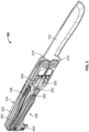
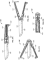
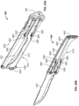
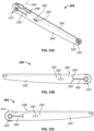
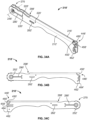
- collapsible knife assemblies shown as folding machetes 100, 100' are illustrated according to exemplary embodiments.
- the folding machetes 100, 100' each include a blade 102, 102' pivotably coupled to a first handle, shown as top handle 104, 104' and a second handle, shown as bottom handle 106, 106'.
- the top handle 104, 104' and the bottom handle 106, 106' are each configured to rotate between an open position and a closed position. In the open position, shown in FIGS. 1-4 , 25 , and 27A , the top handle 104, 104' and the bottom handle 106, 106' extend away from the blade 102, 102'.
- top handle 104, 104' and the bottom handle 106, 106' extend adjacent one another so that a user can wrap their hand around both the top handle 104, 104' and the bottom handle 106, 106' simultaneously to use the folding machete 100, 100'.
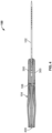
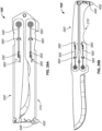
- the top handle 104, 104' and the bottom handle 106, 106' extend along the blade 102, 102', reducing the overall size of the folding machete 100, 100' to facilitate transport and storage.
- the top handle 104, 104' and the bottom handle 106, 106' each define a groove, channel, or slot 108, 108' that extends the entire length of the top handle 104, 104' or the bottom handle 106, 106' (i.e., from a proximal end portion 110, 110' that couples to the blade 102, 102' to a distal end portion 112, 112' opposite the proximal end portion 110, 110').
- the blade 102, 102' (e.g., the entire length of the blade 102, 102', the majority of the length of the blade 102, 102', etc.) is received within the slots 108, 108'.
- the closed position prevents the folding machete 100, 100' from becoming dull prematurely, reduces the likelihood of accidentally cutting another object during transport, and eliminates the need for a sheath.
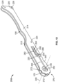
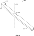
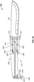
- the blade 102, 102' is formed from a flat piece of material.
- the blade 102, 102' has a pair of main surfaces 120, 120'.
- the main surfaces 120, 120' include a flat portion 122, 122' and a tapered portion 124, 124'.
- the flat portions 122, 122' extend substantially parallel to one another.
- the tapered portions 124, 124' extend toward one another, meeting at a sharpened edge or cutting edge 126, 126'.
- the tapered portions 124, 124' and the cutting edge 126, 126' may be formed by grinding, for example, and may be formed of heat treated or hardened material.
- the cutting edge 126, 126' may be used to cut various materials, such as wood, grasses, sugar cane, coconuts, or meat. Opposite the cutting edge 126, 126', the blade 102, 102' defines a series of notches or jimping 128, 128'.
- the jimping 128, 128' provides a textured surface that may be used as a striking surface to be used for batoning. Batoning is a technique for splitting wood in which the user strikes the top of blade 102, 102' at the jimping 128, 128' (e.g., with a hammer, a mallet, a piece of wood, etc.) to drive the blade 102, 102' deeper into or through the wood being split.
- the blade 102, 102' includes a handle interface section, shown as tang 140, 140', that extends away from the cutting edge 126, 126' and that acts as an interface between the blade 102, 102', the top handle 104, 104', and the bottom handle 106, 106'.
- the tang 140, 140' is formed between the flat portions 122, 122' of the main surfaces 120, 120'.
- the tang 140, 140' defines a series of apertures that extend through both of the main surfaces 120, 120'.
- a first aperture, shown as stop pin aperture 142, 142', is configured to receive a stop pin 144, 144'.
- the stop pin 144, 144' is a cylindrical pin that extends through the blade 102, 102' such that equal lengths of the stop pin 144, 144' extend on each side of the blade 102, 102'.
- the stop pin aperture 142, 142' may be sized as a press fit for the stop pin 144, 144' to hold the stop pin 144, 144' in place.
- the tang 140, 140' further defines a pair of second apertures, shown as handle connection apertures 146, 146'.
- the handle connection apertures 146, 146' facilitate the pivotable connection between the top handle 104, 104', the bottom handle 106, 106', and the blade 102, 102'.
- a pair of third apertures shown as open position apertures 148, 148', a pair of fourth apertures, shown as intermediate position apertures 150, 150', and a pair of fifth apertures, shown as closed position apertures 152, 152', facilitate selectively locking the top handle 104, 104' and the bottom handle 106, 106' in the open position, an intermediate position, and the closed position, respectively.
- the top handle 104, 104' includes a body or top handle frame, shown as frame 200, 200'.
- the frame 200, 200' includes a first body member, shown as plate 202, 202', and a second body member, shown as plate 204, 204'.
- the plate 202, 202' and the plate 204, 204' are laterally offset from one another.
- the slot 108, 108' of the top handle 104, 104' is defined between the plate 202, 202', the plate 204, 204', and the connecting section 206, 206'.
- the plate 202, 202', the plate 204, 204', and the connecting section 206, 206' together have a "U" shaped cross section such that the slot 108, 108' is also "U" shaped.
- the plate 202, 202', the plate 204, 204', and the connecting section 206, 206' are formed from a single sheet of bent material.
- the plate 202, 202' and the plate 204, 204' are substantially the same length.
- the connecting section 206, 206' is shorter than the plate 202, 202' and the plate 204, 204'.
- the bottom handle 106, 106' includes a body or bottom handle frame, shown as frame 210, 210'.
- the frame 210, 210' includes a first body member, shown as plate 212, 212', and a second body member, shown as plate 214, 214'.
- the plate 212, 212' and the plate 214, 214' are laterally offset from one another.
- the slot 108, 108' of the bottom handle 106, 106' is defined between the plate 212, 212', the plate 214, 214', and the connecting section 216, 216'.
- the plate 212, 212', the plate 214, 214', and the connecting section 216, 216' together have a "U" shaped cross section such that the slot 108, 108' is also "U" shaped.
- the plate 212, 212', the plate 214, 214', and the connecting section 216, 216' are formed from a single sheet of bent material.
- the plate 212, 212' and the plate 214, 214' are substantially the same length.
- the connecting section 216, 216' is shorter than the plate 212, 212' and the plate 214, 214'.
- the top handle 104, 104' is configured to engage the palm of a user
- the bottom handle 106, 106' is configured to engage the fingers of a user.
- the frame 200, 200' and the frame 210, 210' are shaped to facilitate this engagement.
- the height of the frame 200, 200' gradually decreases as the frame 200, 200' extends away from the connection to the blade 102, 102' (e.g., away from the proximal end portion 110, 110').
- the height of the frame 210, 210' is substantially constant near the connection to the blade 102, 102'.
- the height of the frame 210, 210' fluctuates to create an ergonomic profile.
- the contour of the frame 210, 210' can be defined by a height that decreases, then increases slightly and decreases again, forming finger rests.
- the height of the frame 210, 210' greatly increases, forming a pommel to prevent the folding machete 100, 100' from slipping out of the user's hand.
- the plate 202, 202', the plate 204, 204', the plate 212, 212', and the plate 214, 214' each define a series of apertures, shown as mounting holes 220, 220'.
- the mounting holes 220, 220' are threaded to receive fasteners 222, 222' that couple other components (e.g., the top scales 300, 300' and the bottom scales 302, 302') to the frame 200, 200' and the frame 210, 210'.
- the plate 202, 202' and the plate 204, 204' each define a first aperture, shown as pin aperture 224, 224'.
- the pin apertures 224, 224' are sized to receive a first dowel or pin, shown as pivot pin 226, 226'.
- the pin apertures 224, 224' and the pivot pin 226, 226' extend perpendicular to the plate 202, 202' and the plate 204, 204'.
- the plate 212 and the plate 214 each define a second aperture, shown as pin aperture 228.
- the pin apertures 228 are sized to receive a second dowel or pin, shown as latch pin 230.
- the pin apertures 228 and the latch pin 230 extend perpendicular to the plate 212 and the plate 214.
- the plate 202, 202', the plate 204, 204', the plate 212, 212', and the plate 214, 214' each define an aperture, shown as handle connection aperture 240, 240'.
- the handle connection apertures 240, 240' are configured to receive a female fastener, shown as outer sleeve 242, 242', and a male fastener, shown as fastener 244, 244'.
- the outer sleeves 242, 242' and the fasteners 244, 244' extend through both of the handle connection apertures 240, 240' of one of the frames and one of the handle connection apertures 146, 146' of the blade 102, 102', pivotably coupling the frame 200, 200' and the frame 210, 210' to the blade 102, 102'.
- the outer sleeves 242, 242' each define an outer surface that engages the edges of the corresponding handle connection apertures 240, 240' and the handle connection aperture 146, 146'.
- the outer sleeves 242, 242' each define a threaded aperture that receives the fastener 244, 244'.
- the handle connection apertures 240, 240', the outer sleeve 242, 242', and the fasteners 244, 244' all extend perpendicular to the plate 202, 202', the plate 204, 204', the plate 212, 212', and the plate 214, 214'. Accordingly, the frame 200, 200' and, by extension, the top handle 104, 104' rotate about an axis of rotation 246, 246' relative to the blade 102, 102'. The frame 210, 210' and, by extension, the bottom handle 106, 106' rotate about an axis of rotation 248, 248' relative to the blade 102, 102'.
- the axis of rotation 246, 246' and the axis of rotation 248, 248' extend perpendicular to the plate 202, 202', the plate 204, 204', the plate 212, 212', the plate 214, 214', and the flat portions 122, 122' of the blade 102, 102'.
- the outer sleeve 242 and one of the handle connection apertures 240 of each frame define corresponding flat surfaces 250 that engage one another to prevent the outer sleeve 242 from rotating relative to the corresponding frame. This prevents the outer sleeves 242 from rotating and loosening the fasteners 244 as the top handle 104 and the bottom handle 106 are rotated relative to the blade 102.
- the plate 202, 202', the plate 204, 204', the plate 212, 212', and the plate 214, 214' each form a circular depression 252, 252' that extends laterally inward toward the slot 108, 108'.
- the circular depressions 252, 252' are centered around the corresponding handle connection apertures 240, 240'.
- the circular depressions 252, 252' may be formed by stamping such that a corresponding circular protrusion extends into the slot 108, 108'.
- the sides of the plate 202, 202', the plate 204, 204', the plate 212, 212', and the plate 214, 214' each define a recess 260, 260' configured to receive the stop pin 144, 144'.
- Engagement between the frame 200, 200' and the stop pin 144, 144' and between the frame 210, 210' and the stop pin 144, 144' ensures that the open positons of the top handle 104, 104' and the bottom handle 106, 106' are consistent each time the folding machete 100, 100' is opened.
- each of the plates 202', 204', 212', 214' define a relief groove 298'.
- the relief groove 298' can be formed away from the recesses 260', and can have a smoothly-curving concave shape extending to the connecting sections 206', 216' of each handle 104', 106'.
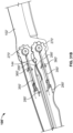
- the plate 204, 204' and the plate 214, 214' each define a gear 270, 270'.
- Each gear 270, 270' includes a series of protrusions, shown as gear teeth 272, 272', extending radially outward along the side of the plate 204, 204' or the plate 214, 214'.
- the gears 270, 270' are radially centered about the axis of rotation 246, 246' and the axis of rotation 248, 248', respectively, such that each of the gear teeth 272, 272' corresponding to the first gear 270, 270' are equidistant from the axis of rotation 246, 246' and each of the gear teeth 272, 272' corresponding to the second gear 270, 270' are equidistant from the axis of rotation 248, 248' (i.e., the pitch circle of each gear 270, 270' is centered about the corresponding axis of rotation).
- the gear teeth 272, 272' of the frame 200, 200' engage the gear teeth 272, 272' of the frame 210, 210', coupling the rotation of the top handle 104, 104' and the rotation of the bottom handle 106, 106'. Accordingly, when the top handle 104, 104' rotates relative to the blade 102, 102', the engagement between the gears 270, 270' causes the bottom handle 106, 106' to rotate relative to the blade 102, 102'. By way of example, when the top handle 104, 104' rotates toward the open position, the gears 270, 270' cause the bottom handle 106, 106' to rotate toward the open position simultaneously.
- Both of the gears 270, 270' have the same pitch diameter and utilize gear teeth 272, 272' having the same diametrical pitch. Accordingly, the gears 270, 270' cause the top handle 104, 104' and the bottom handle 106, 106' to rotate at the same rate relative to the blade 102, 102'.
- the gears 270, 270' facilitate a faster and more controlled opening or closing of the folding machete 100, 100', as a user can control movement of both the top handle 104, 104' and the bottom handle 106, 106' using only one hand.
- the top handle 104, 104' and the bottom handle 106, 106' each include a pair of biasing members 280, 280'.
- spring bars shown as spring tabs 280
- the plate 202, the plate 204, the plate 212, and the plate 214 can each be coupled to a spring tab 280.
- the plate 202, the plate 204, the plate 212, and the plate 214 each define an aperture, shown as spring tab aperture 282, that receives the corresponding spring tab 280.
- Each spring tab 280 includes a longitudinal section 284 and a vertical protrusion 286.
- the longitudinal section 284 extends partway across the corresponding spring tab aperture 282, extending lengthwise along the frame 200 or the frame 210 toward the handle connection aperture 240.
- a proximal end of each longitudinal section 284 is coupled to the corresponding plate.
- the vertical protrusion 286 is coupled to a distal end of the longitudinal section 284 opposite the proximal end.
- the vertical protrusion 286 extends vertically from the longitudinal section 284. Specifically, when the top handle 104 and the bottom handle 106 are in the open position, the vertical protrusion 286 extends toward a longitudinal centerline of the folding machete 100.
- the vertical protrusion 286 of the spring tab 280 coupled to the plate 202 extends toward the plate 212.
- Each spring tab 280 is bent outward from the corresponding plate.
- the spring tab 280 resists bending, applying a biasing force oriented laterally outward from the slot 108.
- the spring tabs 280 are integrally formed with the frame 200 or the frame 210.
- the top handle 104' and bottom handle 106' can each include torsion springs 280'.
- the torsion springs 280' can be positioned within apertures 282' that extend through each of the plates 202', 204', 212', 214'.
- Each handle 104', 106' can include two torsion springs 280' that are coupled to the handles 104', 106'.
- Each torsion spring 280' can be anchored to one of the plates 202', 204', 212', 214', and extend laterally outward, away from the plate 202' 204', 212', 214' the torsion spring 280' is anchored to.
- the torsion springs 280' provide a rotational bias that resists rotation inward, toward the plates 202', 204', 212', 214'.
- different types of biasing members can be used, such as compression springs that engage the plate 202, for example.
- the plate 202, 202', the plate 204, 204', the plate 212, 212', and the plate 214, 214' each also define an aperture, shown as catch slot 290, 290'.
- the catch slot 290, 290' extends lengthwise along the frame 200, 200' or the frame 210, 210'.
- the catch slot 290, 290' extends between the handle connection aperture 240, 240' and the aperture 282, 282'.
- the catch slot 290 can be aligned with the vertical protrusion 286 of the spring tab 280.
- the catch slot 290' can be offset from the aperture 282'.
- the frame 210, 210' defines an aperture, shown as lanyard aperture 294, 294'.
- a protrusion, shown as lanyard protrusion 296, 296' extends laterally outward from the plate 212, 212', away from the slot 108, 108'.
- the lanyard aperture 294, 294' is defined between the lanyard protrusion 296, 296' and the plate 212, 212'.
- a lanyard may extend through the lanyard aperture 294, 294' and tie around the lanyard protrusion 296, 296' to facilitate hanging the folding machete 100, 100' during transportation or storage.
- the folding machete 100, 100' further includes a pair of first bodies or covers, shown as top scales 300, 300', and a pair of second bodies or covers, shown as bottom scales 302, 302'.
- the top scales 300, 300' are coupled to the plate 202, 202' and the plate 204, 204', respectively, and the bottom scales 302, 302' are coupled to the plate 212, 212' and the plate 214, 214', respectively.
- the top scales 300, 300' and the bottom scales 302, 302' increase the overall width of the top handle 104, 104' and the bottom handle 106, 106' and have shaped and textured outer surfaces that facilitate a user comfortably and securely holding the folding machete 100, 100'.
- the top scales 300, 300' and the bottom scales 302, 302' define apertures, shown as mounting holes 310, 310'.
- the fasteners 222, 222' extend through the mounting holes 310, 310' and into the mounting holes 220, 220' to couple the top scales 300, 300' and the bottom scales 302, 302' to the frame 200, 200' and the frame 210, 210', respectively.
- the top scales 300, 300' and the bottom scales 302, 302' each include a cylindrical protrusion 312.
- the cylindrical protrusions 312 are received within the circular depressions 252, 252'.
- the top scales 300, 300' and the bottom scales 302, 302' further define handle connection apertures 314 at the center of the cylindrical protrusions 312.
- the handle connection apertures 314 receive the outer sleeves 242, 242' and the fasteners 244, 244' therethrough.
- the fasteners 244, 244' and the outer sleeves 242, 242' press against the top scales 300, 300' and the bottom scales 302, 302', preventing separation of the top scales 300, 300' and the bottom scales 302, 302' from the frame 200, 200' and the frame 210, 210'.
- the top scales 300, 300' and the bottom scales 302, 302' further define recesses, shown as pin recesses 316, that extend partway through the top scales 300, 300' and the bottom scales 302, 302'.
- the pin recesses 316 receive the ends of the pivot pin 226, 226' and the latch pin 230 such that the top scales 300, 300' or the bottom scales 302, 302' engage the pivot pin 226, 226' and the latch pin 230. Because the pin recesses 316 do not extend through the entirety of the top scales 300, 300' and the bottom scales 302, 302', the pivot pin 226, 226' and the latch pin 230 are prevented from moving out of the frame 200, 200' or the frame 210, 210'.
- the top scales 300, 300' and the bottom scales 302, 302' further define recesses, shown as stop pin recesses 318.
- the stop pin recesses 318 are semicircular and arranged along a side of the top scales 300, 300' and the bottom scales 302, 302' such that the stop pin recesses 318 receive the stop pin 144, 144' when the top handle 104, 104' and the bottom handle 106, 106' are in the open positions.
- the stop pin 144, 144' passes out of the stop pin recesses 318.
- the top scales 300, 300' and the bottom scales 302, 302' each further define a first recess, shown as catch pin recess 320, an aperture, shown as catch aperture 322, 322', and a second recess, shown as catch recess 324.
- the pin recesses 316, the stop pin recesses 318, the catch pin recess 320, and the catch recesses 324 all extend laterally outward from an inside surface of the top scale 300, 300' or the bottom scale 302, 302'.
- the top handle 104, 104' and the bottom handle 106, 106' each further include a pair of levers or locking members, shown as catches 350, 350'.
- the catches 350, 350' include a first section 352, 352' and second section 354, 354'.
- Each catch 350, 350' defines an aperture, shown as pin aperture 356, 356', positioned between the first section 352, 352' and the second section 354, 354'.
- a protrusion, shown as locking protrusion 358, 358' extends away from the end of the first section 352, 352' opposite the second section 354, 354'.
- the catches 350, 350' are each coupled to the frame 200, 200' or the frame 210, 210' by a pin, shown as catch pin 360, 360'.
- the catch pins 360, 360' extend though the pin aperture 356, 356' to pivotably couple the catch 350, 350' to the corresponding catch pin 360, 360'.
- the catches 350, 350' rotate about an axis of rotation 362, 362' that extends parallel to the catch pin 360, 360' and the pin aperture 356, 356'.
- the catch pins 360, 360' are received by the catch pin recesses 320, holding the catches 350, 350' in place relative to the frame 200, 200' and the frame 210, 210'.
- the catches 350 are received within the catch recesses 324, and the second sections 354 of the catches 350 extend outward through the catch apertures 322, as demonstrated in FIGS. 1 and 2 .
- the vertical protrusions 286 of the spring tabs 280 engage the second sections 354, biasing the second sections 354 laterally outward, away from the slots 108, and through the catch apertures 322.
- the spring tabs 280 bias the catches 350 toward an engaged position.
- the torsion springs 280' can engage the second sections 354', biasing the second sections 354 laterally outward, away from the slots 108', and through the catch apertures 322'.
- the rotational bias supplied by the torsion springs 280' urges the catches 350' inward, about the catch pin 360', toward an engaged position.
- a user may apply a force on the second section 354, 354' toward the slots 108, 108' to move or rotate the catches 350, 350' toward a disengaged position.
- the catches 350, 350' are located in the same longitudinal and vertical positions on the top handle 104, 104' and on the bottom handle 106, 106' such that a user can pinch the second sections 354, 354' toward one another to move the catches 350, 350' toward the disengaged positions.
- the catches 350, 350' when the catches 350, 350' are in the engaged positions, the catches 350, 350' extend through the catch slots 290, 290' to engage the blade 102, 102'.
- the catch slots 290, 290' align with the open position apertures 148, 148', the closed position apertures 152, 152', and the intermediate position apertures 150, 150', respectively. As shown in FIGS.
- the locking protrusions 358, 358' extend into the open position apertures 148, 148', the closed position apertures 152, 152', or the intermediate position apertures 150, 150'.
- the locking protrusions 358, 358' engage the blade 102, 102', preventing relative rotation between the blade 102, 102', the top handle 104, 104', and the bottom handle 106, 106'.
- the biasing members 280, 280' bias the catches 350, 350' toward the engaged positions, the locking protrusions 358, 358' automatically engage the open position apertures 148, 148', the closed position apertures 152, 152', or the intermediate position apertures 150, 150' as the top handle 104, 104' and the bottom handle 106, 106' are rotated.
- FIGS. 7 and 32 illustrate the open positions, closed positions, and intermediate positions of the top handle 104, 104' and the bottom handle 106, 106'.
- the locations of the open positions, closed positions, and intermediate positions are based on the positions of the open position aperture 148, 148', the intermediate position aperture 150, 150', and the closed position aperture 152, 152'.
- the top handle 104 extends along axis Pci in the closed position, along the axis P I1 in the intermediate position, and along the axis Poi in the open position.
- the bottom handle 106 extends along axis P C2 in the closed position, along the axis P I2 in the intermediate position, and along the axis P O2 in the open position.
- the open position is angularly offset from the closed position by a first angle ⁇ 1
- the closed position is angularly offset from the intermediate position by a second angle ⁇ 2
- the open position is angularly offset from the intermediate position by a third angle ⁇ 3 .
- the angle ⁇ 1 is approximately 180 degrees. Accordingly, as shown, the open and closed positions of the top handle 104 and the bottom handle 106 are substantially parallel. In other embodiments, the angle ⁇ 1 is less than 180 degrees.
- the angle ⁇ 2 is less than the angle ⁇ 3 (e.g., 15 degrees, 30 degrees, 45 degrees, 60 degrees, etc.).
- each positioning aperture 148', 150', 152' can be adjusted to accommodate for differently-sized handles 104', 106' as well. As depicted in FIG. 32 , each positioning aperture 148', 150', 152' is spaced, equidistantly, from one of the connection apertures 146'. Each aperture 148', 150', 152' can be positioned about and extend away from a reference circle RC concentric with the connection apertures 146'. In some embodiments, the open position apertures 148' and the closed position apertures 152' are aligned with one another to extend coaxially away from the nearby connection aperture 146'.
- the open position apertures 148' and the closed position apertures 152' are positioned 180 degrees apart from one another on the reference circle RC. Additionally or alternatively, the blade 102' can defined by the various angular and axial relationships described above with respect to the blade 102 in the folding machete 100.
- a user may use the folding machete 100, 100' with the top handle 104, 104' and the bottom handle 106, 106' in the open positions.
- the catches 350, 350' hold the top handle 104, 104' and the bottom handle 106, 106' in place.
- they may press all of the catches 350, 350' toward the disengaged positions.
- the user may then apply a torque to one or both of the top handle 104, 104' and the bottom handle 106, 106' to rotate the top handle 104, 104' and the bottom handle 106, 106' toward the closed positions.
- the user may choose to apply the torque to only one of the top handle 104, 104' and the bottom handle 106, 106', as the gears 270, 270' cause the top handle 104, 104' and the bottom handle 106, 106' to rotate in unison.
- the user may release the catches 350, 350', which then engage the flat portions 122, 122' of the main surface 120, 120' of the blade 102, 102'.
- the biasing members 280, 280' rotate the catches 350, 350' into the engaged positions, forcing the protrusions 258, 258' into the intermediate position apertures 150, 150'.
- the intermediate position apertures 150, 150' are closer to the closed position apertures 152, 152' than the open position apertures 148, 148'. Accordingly, the top handle 104, 104' and the bottom handle 106, 106' are closer to the closed position than to the open position when in the intermediate position.
- the intermediate position facilitates stopping the top handle 104, 104' and the bottom handle 106, 106' near the closed position, providing the user with an opportunity to readjust their grip on the top handle 104, 104' and/or the bottom handle 106, 106'.
- the intermediate position prevents the user from accidentally pinching their fingers between the blade 102, 102' and the top handle 104, 104' or the bottom handle 106, 106'.
- the user may again press all of the catches 350, 350' toward the disengaged positions.
- the user may then apply a torque to one or both of the top handle 104, 104' and the bottom handle 106, 106' to rotate the top handle 104, 104' and the bottom handle 106, 106' toward the closed positions.
- the user may release the catches 350, 350', which then engage the flat portions 122, 122' of the main surface 120, 120' of the blade 102, 102'.
- the biasing members 280, 280' rotate the catches 350, 350' into the engaged positions, forcing the protrusions 258, 258' into the closed position apertures 152, 152', holding the top handle 104, 104' and the bottom handle 106, 106' in the closed positions.
- the user may complete this process again in reverse order.
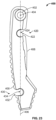
- the folding machete 100, 100' further includes a locking member, shown as latch 400, 400'.
- the latch 400, 400' defines an aperture, shown as pin aperture 402, 402'.
- the pin aperture 402, 402' is configured to receive the pivot pin 226, 226', thereby pivotably coupling the latch 400, 400' to the frame 200, 200'.
- the latch 400, 400' is received within the slots 108, 108' of the top handle 104, 104' and the bottom handle 106, 106' near the distal end portions 112, 112'.
- the latch 400, 400' is configured to rotate about an axis of rotation 404, 404' relative to the frame 200, 200' that extends laterally.
- the latch 400, 400' extends away from the axis of rotation 404, 404' about an axis of extension 406, 406'.
- the axis of extension 406, 406' extends perpendicular to the axis of rotation 404, 404'.
- a first surface of the latch 400, 400', shown as first side 408, 408' extends on a first side of the axis of extension 406, 406', and a second surface of the latch 400, 400', shown as second side 410, 410', extends on an opposite side of the axis of extension 406, 406'.
- the latch 400 defines a first recess, groove, notch, or slot, shown as open position groove 420.
- the open position groove 420 extends toward the axis of extension 406 from the first side 408 (e.g., extends laterally outward from the axis of extension 406).
- the open position groove 420 has a first section 422 that is nearest the first side 408 (e.g., defines the opening to the open position groove 420) and a second section 424 that is positioned farther from the first side 408. Accordingly, the first section 422 is positioned between the first side 408 and the second section 424.
- the first section 422 has a first width
- the second section 424 has a second width greater than the first width. The first width is less than the thickness (e.g., diameter) of the latch pin 230.
- the latch 400 can define a second recess, groove, notch, or slot, shown as closed position groove 430.
- the closed position groove 430 extends toward the axis of extension 406 from the second side 410 (e.g., extends laterally outward from the axis of extension 406).
- the closed position groove 430 has a first section 432 that is nearest the second side 410 (e.g., defines the opening to the closed position groove 430) and a second section 434 that is positioned farther from the second side 410. Accordingly, the first section 432 is positioned between the second side 410 and the second section 434.
- the open position groove 420 and the closed position groove 430 extend in substantially opposite directions.
- the first section 432 has a third width
- the second section 424 has a fourth width greater than the third width.
- the third width is less than the thickness (e.g., diameter) of the latch pin 230.
- the first width may be substantially equal to the third width
- the second width may be substantially equal to the fourth width.
- the open position groove 420 can be positioned a first distance away from the axis of rotation 404.
- the closed position groove 430 is positioned a second distance away from the axis of rotation 404.
- the pivot pin 226 and the latch pin 230 are spaced apart by the second distance such that the latch 400 can be rotated to receive the latch pin 230 within the closed position groove 430.
- the latch 400 prevents the top handle 104 and the bottom handle 106 from moving out of the closed position. Accordingly, the latch 400 may be used with or without the catches 350 to hold the top handle 104 and the bottom handle 106 in the desired position.
- the latch pin 230 deforms the latch 400.
- the latch 400 may be made from a material that elastically deforms under such loading (e.g., plastic, etc.). As such, the reduced width of the first section 422 and the first section 432 ensure that the latch pin 230 has a "snap fit" into the open position groove 420 or the closed position groove 430. This provides resistance to entering and exiting the open position groove 420 or the closed position groove 430, preventing the latch 400 from accidentally becoming engaged or disengaged.
- the latch 400' can have a locking pin design that selectively engages the bottom handle 106'.
- the latch 400' can have a series of grooves 436' formed into the first side 408' and second side 410' of the latch 400'.
- the grooves 436' can extend partially or entirely through the latch 400', and can be sized to receive fasteners 222'.
- the grooves 436' formed in the first side 408' of the latch 400' can face away from the grooves 436' formed in the second side 410' of the latch 400'.
- the latch 400' can further define a groove wall 438' positioned axially between each groove 436'.
- the latch 400' is formed by a sandwich assembly of latch bodies.
- Two external bodies 440' surround an internal body 442' having a different profile than the external bodies 440'.
- the internal body 442' may not include grooves 436', and can extend across each groove 436' to define the groove walls 438'.
- the external bodies 440' are formed of a different material than the internal body 442'.
- the internal body 442' may be formed from metal, while the external bodies 440' can be formed of a polymeric or, more specifically, an elastomeric material like rubber.
- the latch 400' further defines a locking pin aperture 444'.
- the locking pin aperture 444' is positioned opposite the pin aperture 402' and can extend entirely through the latch 400' (e.g., through each of the latch bodies 440', 442').
- the locking pin aperture 444' is sized to receive and secure a locking pin 446'.
- the locking pin 446' can form an interference fit with the locking pin aperture 444' and can be positioned within the locking pin aperture 444' to extend axially outward beyond the external bodies 440' equally in both directions.
- the locking pin 446' can engage and interact with different portions of the bottom handle 106' to secure the top handle 104' and the bottom handle 106' to one another.
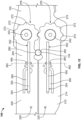
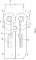
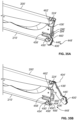
- the latch rotates into selective engagement with a hook-and-spring locking mechanism 448'.
- Hooks 450' extend away from the distal end portion 112' of the handle 106', and define a gap 452' that can receive a portion of the latch 400'.
- the hooks 450' are formed integrally with each frame 212', 214' of the bottom handle frame 210'.
- the hooks 450' define a concave surface 454' that can be sized to receive and secure the locking pin 446'.
- the concave surface 454' includes a peak 456' formed at an outermost edge of each hook 450'.
- a spring bar 458' can be formed integrally with the bottom handle frame 210' as well.
- the spring bar 458' cantilevers outward from the frame 210', and includes a downward-extending projection 460'.
- the downward extending projection 460' can contact and secure the locking pin 446' into the hook-and-spring locking mechanism 448'.
- the latch 400' is swung to a closed position, the locking pin 446' contacts the peak 456' and the projection 460', urging the hooks 450' downward and urging the spring bar 458' upward.
- the resilience of the hooks 450' and the spring bar 458' allow limited rotation relative to the frame 210', which allows the locking pin 446' to pass beyond the peak 456' and projection 458', where it can be received and secured upon the concave surfaces 454' of each hook 450'.
- the grooves 436' receive fasteners 222' extending through each frame 200', 210'.
- the hooks 450' and spring bar 458' attempt to return to rest positions, and engage the locking pin 446' to further secure the locking pin 446' within the hook-and-spring locking mechanism 448' because the gap between the protrusion 460' and the concave surface 454' is smaller than a diameter defining the locking pin 446'. Rotation in the opposite direction can be used to unlock the latch 400' from the hook-and-spring locking mechanism 448'.
- the latch 400' can lock the handles 104', 106' in the open position as well. As depicted in FIGS. 36A-36B , the latch 400' can engage the bottom handle frame 210', opposite the hook-and-spring locking mechanism 448'.
- concave locking surfaces 462' can be formed in each plate 212', 214'.
- the locking surfaces 462' can include multiple inflection points and can be sized to receive and secure the locking pin 446', which then prevents rotation between the two handles 104', 106'.
- the latch 400' is rotated from the top handle 104' toward the bottom handle 106'.
- the locking pin 446' initially engages an entrance peak 464' formed in the locking surface 462'. Additional rotational force allows the latch 400', handle 106', or a combination of the two components to flex slightly, allowing passage of the locking pin 446' beyond the entrance peak 464'. Continued rotation of the latch 400' allows the locking pin 446' to rotate into engagement with the locking surface 462', which can be defined by a radius similar to that of the locking pin 446'. When the locking pin 446' rotates into engagement with the locking surface 462', the grooves 436' each rotate into engagement with fasteners 222' extending inward from the frames 200', 210'.
- Rotational force in the opposite direction can swing the latch 400' and the locking pin 446' outward, where the handle 106' and/or the latch 400' flex until the locking pin 446' has advanced beyond the entrance peak 464', when the latch 400' can swing freely.
- the folding machete 100, 100' is a machete having dimensions that facilitate use as a machete.
- a distance D 1 is defined between the latch 400 and the ends of the top handle 104 and the bottom handle 106 opposite the latch 400
- a distance D 2 is defined between the ends of the top handle 104 and the bottom handle 106 opposite the latch 400 and the tip of the blade 102
- an overall length of the folding machete 100 is defined as a distance D 3 .
- an overall length of the folding machete 100 is defined as a distance D 4 .
- the distance D 1 is approximately 8.4 inches
- the distance D 2 is approximately 7.0 inches
- the distance D 3 is approximately 15.4 inches
- the distance D 4 is approximately 9 inches. In other embodiments, these dimensions may vary.
- the distance D 2 may be 5 inches, 6 inches, 8 inches, or more. Similar dimensional relationships can be used in the folding machete 100'.
- the top handle 104 and the latch 400 are omitted, and solely the bottom handle 106 is used to manipulate the folding machete 100.
- the catches 350 stop the bottom handle 106 from moving inadvertently.
- one or more of the catches 350 are omitted. With only one catch 350, the gears 270 prevent the handle without the catch from moving inadvertently. With no catches 350, the latch 400 prevents the top handle 104 and the bottom handle 106 from moving out of the closed position or the open position inadvertently.
- the frame 200 and the top scales 300 are integrally formed as a single body, and the frame 210 and the bottom scales 302 are integrally formed as a single body.
Landscapes
- Life Sciences & Earth Sciences (AREA)
- Forests & Forestry (AREA)
- Engineering & Computer Science (AREA)
- Mechanical Engineering (AREA)
- Knives (AREA)
Applications Claiming Priority (3)
| Application Number | Priority Date | Filing Date | Title |
|---|---|---|---|
| US201862670364P | 2018-05-11 | 2018-05-11 | |
| PCT/IB2019/053885 WO2019215699A2 (en) | 2018-05-11 | 2019-05-10 | Folding machete |
| EP19732732.3A EP3790713B1 (de) | 2018-05-11 | 2019-05-10 | Abkantmesser |
Related Parent Applications (2)
| Application Number | Title | Priority Date | Filing Date |
|---|---|---|---|
| EP19732732.3A Division EP3790713B1 (de) | 2018-05-11 | 2019-05-10 | Abkantmesser |
| EP19732732.3A Division-Into EP3790713B1 (de) | 2018-05-11 | 2019-05-10 | Abkantmesser |
Publications (2)
| Publication Number | Publication Date |
|---|---|
| EP4272912A2 true EP4272912A2 (de) | 2023-11-08 |
| EP4272912A3 EP4272912A3 (de) | 2024-02-21 |
Family
ID=67002066
Family Applications (2)
| Application Number | Title | Priority Date | Filing Date |
|---|---|---|---|
| EP19732732.3A Active EP3790713B1 (de) | 2018-05-11 | 2019-05-10 | Abkantmesser |
| EP23199190.2A Pending EP4272912A3 (de) | 2018-05-11 | 2019-05-10 | Faltmaschine |
Family Applications Before (1)
| Application Number | Title | Priority Date | Filing Date |
|---|---|---|---|
| EP19732732.3A Active EP3790713B1 (de) | 2018-05-11 | 2019-05-10 | Abkantmesser |
Country Status (4)
| Country | Link |
|---|---|
| US (3) | US11298836B2 (de) |
| EP (2) | EP3790713B1 (de) |
| CN (2) | CN115194828B (de) |
| WO (1) | WO2019215699A2 (de) |
Families Citing this family (17)
| Publication number | Priority date | Publication date | Assignee | Title |
|---|---|---|---|---|
| US10882197B1 (en) * | 2018-04-12 | 2021-01-05 | Gb Ii Corporation | Easily disassembled folding knife |
| EP3894147B1 (de) * | 2018-12-13 | 2023-09-06 | Benchmade Knife Co., Inc. | Riegelloser verriegelungsmechanismus für schmetterlingsmesser |
| USD920763S1 (en) * | 2019-11-26 | 2021-06-01 | Heed Industries Inc. | Knife |
| TWD211882S (zh) * | 2020-07-24 | 2021-06-01 | 青輔實業股份有限公司 | 懸臂裝置 |
| USD945244S1 (en) * | 2020-08-24 | 2022-03-08 | Benchmade Knife Co., Inc. | Handle extension for a knife |
| US11472045B2 (en) * | 2020-10-30 | 2022-10-18 | Shaoching Sung | Knife |
| USD994827S1 (en) * | 2021-10-04 | 2023-08-08 | Benchmade Knife Co., Inc. | Knife |
| USD1001229S1 (en) * | 2021-10-04 | 2023-10-10 | Benchmade Knife Co., Inc. | Knife |
| USD994826S1 (en) * | 2021-10-04 | 2023-08-08 | Benchmade Knife Co., Inc. | Knife |
| USD1018248S1 (en) * | 2022-07-06 | 2024-03-19 | Benchmade Knife Co., Inc. | Knife handle extension |
| USD1020427S1 (en) * | 2022-07-06 | 2024-04-02 | Benchmade Knife Co., Inc. | Knife |
| US12539628B2 (en) * | 2022-07-06 | 2026-02-03 | Benchmade Knife Co., Inc. | Adjustable weighting system in knife handles |
| USD974143S1 (en) * | 2022-10-24 | 2023-01-03 | William Everett Hirsch | Butterfly knife |
| USD1032320S1 (en) | 2022-11-22 | 2024-06-25 | Benchmade Knife Co., Inc. | Knife |
| USD1047652S1 (en) * | 2022-12-13 | 2024-10-22 | Fiskars Brands, Inc. | Folding knife |
| USD1098869S1 (en) * | 2024-01-12 | 2025-10-21 | Ken Onion Hawaii, Llc | Folding knife |
| USD1098870S1 (en) * | 2024-01-12 | 2025-10-21 | Ken Onion Hawaii, Llc | Folding knife |
Family Cites Families (49)
| Publication number | Priority date | Publication date | Assignee | Title |
|---|---|---|---|---|
| US1665955A (en) * | 1928-04-10 | Knife structure | ||
| US881294A (en) * | 1907-11-11 | 1908-03-10 | Charles E Billings | Knife. |
| US1353490A (en) * | 1915-08-19 | 1920-09-21 | Pantalek John | Safety pocket-knife |
| US2714249A (en) * | 1953-07-13 | 1955-08-02 | Dixon W Clark | Folding knife |
| US3702501A (en) * | 1968-11-20 | 1972-11-14 | Barry Bertram Wood | Split handle jack knife |
| US4330937A (en) * | 1980-07-25 | 1982-05-25 | Cope James R | Fish filletting knife |
| US4364174A (en) * | 1981-04-27 | 1982-12-21 | Lester De Asis | Apparatus and improved method of manufacturing handles for butterfly defense knife |
| US4547965A (en) * | 1982-04-16 | 1985-10-22 | Moore Donald M | Synchronized folding knife |
| US4648145A (en) * | 1983-03-28 | 1987-03-10 | Miceli Philip V | Folding pocket tool and knife |
| US4669140A (en) * | 1984-06-25 | 1987-06-02 | Miceli Philip V | Pocket folding tool and knife system |
| US4555822A (en) * | 1984-11-14 | 1985-12-03 | Miceli Philip V | Knife system with removable-accessory handle lock |
| US4730393A (en) * | 1986-01-17 | 1988-03-15 | W.R. Case & Sons Cutlery Co. | Locking knife with movable scale |
| US4722140A (en) | 1986-01-22 | 1988-02-02 | Miceli Philip V | Knife system |
| US4672743A (en) * | 1986-09-15 | 1987-06-16 | Grahm Robert D | Folding hand knife |
| US5809599A (en) | 1993-11-29 | 1998-09-22 | Sog Specialty Knives, Inc. | Compound pliers tool with linked handles |
| US6282997B1 (en) | 1993-11-29 | 2001-09-04 | Sog Specialty Knives, Inc. | Multipurpose tool and components thereof |
| US6070504A (en) | 1998-04-22 | 2000-06-06 | Sog Specialty Knives, Inc. | Compound pliers tool with linked handles |
| US6195898B1 (en) * | 1998-12-04 | 2001-03-06 | Adam M. Lemisch | Magnetically latching butterfly knife |
| US6161291A (en) | 1998-12-16 | 2000-12-19 | Gilmour, Inc. | Lopping apparatus having handle compartments for stowing blades during periods of non-use and associated method |
| US6170158B1 (en) * | 1999-06-08 | 2001-01-09 | Delta Z Knives, Inc. | Pocket knife |
| US6550142B1 (en) | 2001-10-09 | 2003-04-22 | Taylor Cutlery | Hand tool with retractable implement |
| US6848183B2 (en) * | 2002-08-12 | 2005-02-01 | Adam M. Lemisch | Thumb lock for a butterfly knife |
| US6715208B2 (en) * | 2002-08-12 | 2004-04-06 | Adam M. Lemisch | Thumb lock for a butterfly knife |
| CA2491948C (en) * | 2004-01-13 | 2009-07-14 | Leatherman Tool Group, Inc. | Multipurpose folding tool with tool bit holder and blade lock |
| US7752759B2 (en) * | 2005-01-19 | 2010-07-13 | Perreault Daniel C | Folding knife and related methods |
| US7681316B2 (en) * | 2005-09-16 | 2010-03-23 | Kai U.S.A., Ltd. | Folding knife having a locking mechanism |
| US20070137047A1 (en) * | 2005-12-15 | 2007-06-21 | Surefire, Llc, A California Limited Liability Company | Folding knife |
| FI121534B (fi) | 2006-05-09 | 2010-12-31 | Fiskars Brands Finland Oy Ab | Leikkuutyökalu |
| US7325312B1 (en) * | 2006-12-08 | 2008-02-05 | Blackhawk Industries Product Group Unlimited Llc | Folding knife with pivoting blade and guard |
| US20080222896A1 (en) * | 2007-03-12 | 2008-09-18 | Microtech Knives, Inc. | Field strippable knife |
| US7676930B1 (en) * | 2007-06-12 | 2010-03-16 | Cold Steel | Dual handle safety folding knife |
| US8147159B2 (en) | 2007-11-29 | 2012-04-03 | Spyderco, Inc. | Writing instrument with rotatable handles |
| US8393069B2 (en) | 2007-11-29 | 2013-03-12 | Spyderco, Inc. | Writing instrument with rotatable handles and method for making the same |
| CN202016055U (zh) * | 2011-01-30 | 2011-10-26 | 上海昆杰五金工具有限公司 | 一种折叠刀 |
| TWM425751U (en) * | 2011-11-29 | 2012-04-01 | Yan-Fen Luo | Foldable knife with assisted opening fastening toggle key |
| US8973273B2 (en) * | 2012-01-13 | 2015-03-10 | Stanley Black & Decker, Inc. | Foldable chisel |
| CN102990680B (zh) * | 2012-11-28 | 2015-02-04 | 杭州巨星科技股份有限公司 | 多档位刀 |
| US9597809B2 (en) * | 2013-03-04 | 2017-03-21 | Gb Ii Corporation | Easily disassembled folding knife |
| US20140259687A1 (en) * | 2013-03-14 | 2014-09-18 | Bear & Son Cutlery, Inc. | Knife with assisted opening mechanism |
| USD710166S1 (en) * | 2013-04-11 | 2014-08-05 | Stanley Black & Decker Inc. | Folding chisel |
| WO2015175465A1 (en) * | 2014-05-16 | 2015-11-19 | Mentor Group, L.L.C. | Apparatus and method of installing bearings in a one-piece handle |
| US9737997B1 (en) * | 2014-05-30 | 2017-08-22 | Marfione Custom Knives, LLC | Rotatable safety mechanism for automatic folding knife |
| US9833912B2 (en) | 2014-09-15 | 2017-12-05 | Gb Ii Corporation | Folding knife with locking mechanism |
| CN204604359U (zh) * | 2015-04-20 | 2015-09-02 | 馥民实业股份有限公司 | 折叠刀具 |
| US20160368155A1 (en) * | 2015-06-16 | 2016-12-22 | Marfione Custom Knives, LLC | Knife Clip |
| USD854393S1 (en) * | 2017-08-21 | 2019-07-23 | Great Neck Saw Manufacturers, Inc. | Safety scraper |
| CN107379023A (zh) * | 2017-08-24 | 2017-11-24 | 启俊集团有限公司 | 一种折叠刀 |
| CN207172139U (zh) * | 2017-09-01 | 2018-04-03 | 广东凯泽户外用品有限公司 | 一种带暗锁扣的蝴蝶刀 |
| CN207139854U (zh) * | 2017-09-13 | 2018-03-27 | 李灵娇 | 多功能折叠刀 |
-
2019
- 2019-05-10 EP EP19732732.3A patent/EP3790713B1/de active Active
- 2019-05-10 US US16/408,551 patent/US11298836B2/en active Active
- 2019-05-10 CN CN202210598225.6A patent/CN115194828B/zh active Active
- 2019-05-10 WO PCT/IB2019/053885 patent/WO2019215699A2/en not_active Ceased
- 2019-05-10 EP EP23199190.2A patent/EP4272912A3/de active Pending
- 2019-05-10 CN CN201980029902.9A patent/CN112292240B/zh active Active
-
2022
- 2022-04-11 US US17/717,908 patent/US11697214B2/en active Active
-
2023
- 2023-06-22 US US18/339,736 patent/US12179371B2/en active Active
Also Published As
| Publication number | Publication date |
|---|---|
| EP4272912A3 (de) | 2024-02-21 |
| US12179371B2 (en) | 2024-12-31 |
| US20230330874A1 (en) | 2023-10-19 |
| EP3790713A2 (de) | 2021-03-17 |
| US11298836B2 (en) | 2022-04-12 |
| EP3790713B1 (de) | 2023-11-01 |
| WO2019215699A2 (en) | 2019-11-14 |
| CN115194828B (zh) | 2024-08-27 |
| CN112292240A (zh) | 2021-01-29 |
| US11697214B2 (en) | 2023-07-11 |
| US20190344457A1 (en) | 2019-11-14 |
| WO2019215699A3 (en) | 2020-02-13 |
| CN115194828A (zh) | 2022-10-18 |
| US20220234221A1 (en) | 2022-07-28 |
| CN112292240B (zh) | 2022-07-01 |
Similar Documents
| Publication | Publication Date | Title |
|---|---|---|
| US20220234221A1 (en) | Folding machete | |
| US10136583B2 (en) | Geared hand tool | |
| US6438848B1 (en) | Folding tool with a lock and automatic opener | |
| EP3946817B1 (de) | Mehrzweckwerkzeug mit laminierten zangenbacken | |
| US7299724B1 (en) | Self-adjusting gripping tool | |
| AU2020267258B2 (en) | Pipe wrench | |
| CN121290325A (zh) | 折叠工具 | |
| DE9110772U1 (de) | Gartenschere | |
| US8984990B2 (en) | Lockable grip wrench | |
| US20060005397A1 (en) | Folding tool with blade locking mechanism | |
| US11130246B2 (en) | Locking folding knife and knife lock mechanism | |
| CN102307706B (zh) | 可调节扳手 | |
| KR20190143357A (ko) | 하나 이상의 회전가능한 공구 부재를 갖는 공구 | |
| US20220395992A1 (en) | Tile Nipper | |
| US6240764B1 (en) | J-channel siding cutter | |
| US7987601B2 (en) | Folding tool | |
| JP6236179B1 (ja) | ウォーターポンププライヤ、およびカバー部材 | |
| DE102016125517B4 (de) | Handwerkzeug mit einer Ratschenfunktion | |
| DE69821034T2 (de) | Klapptaschenmesser mit verriegelung | |
| EP3656730B1 (de) | Als pfandmünze und kapselheber verwendbares flaches werkzeug | |
| US6802125B2 (en) | Cable-stripping tool | |
| KR101908592B1 (ko) | 절삭물 부착방지 홈이 구비된 가위 | |
| DE202008001949U1 (de) | Greifzange | |
| WO2014202101A1 (en) | Fixing mechanism of devices on a multi-purpose tool | |
| EP3112092A1 (de) | Handwerkzeug für halbseitengelähmte menschen |
Legal Events
| Date | Code | Title | Description |
|---|---|---|---|
| PUAI | Public reference made under article 153(3) epc to a published international application that has entered the european phase |
Free format text: ORIGINAL CODE: 0009012 |
|
| STAA | Information on the status of an ep patent application or granted ep patent |
Free format text: STATUS: REQUEST FOR EXAMINATION WAS MADE |
|
| 17P | Request for examination filed |
Effective date: 20230922 |
|
| AC | Divisional application: reference to earlier application |
Ref document number: 3790713 Country of ref document: EP Kind code of ref document: P |
|
| AK | Designated contracting states |
Kind code of ref document: A2 Designated state(s): AL AT BE BG CH CY CZ DE DK EE ES FI FR GB GR HR HU IE IS IT LI LT LU LV MC MK MT NL NO PL PT RO RS SE SI SK SM TR |
|
| RIC1 | Information provided on ipc code assigned before grant |
Ipc: B26B 1/04 20060101AFI20231017BHEP |
|
| PUAL | Search report despatched |
Free format text: ORIGINAL CODE: 0009013 |
|
| AK | Designated contracting states |
Kind code of ref document: A3 Designated state(s): AL AT BE BG CH CY CZ DE DK EE ES FI FR GB GR HR HU IE IS IT LI LT LU LV MC MK MT NL NO PL PT RO RS SE SI SK SM TR |
|
| RIC1 | Information provided on ipc code assigned before grant |
Ipc: B26B 1/04 20060101AFI20240117BHEP |
|
| GRAP | Despatch of communication of intention to grant a patent |
Free format text: ORIGINAL CODE: EPIDOSNIGR1 |
|
| STAA | Information on the status of an ep patent application or granted ep patent |
Free format text: STATUS: GRANT OF PATENT IS INTENDED |
|
| INTG | Intention to grant announced |
Effective date: 20260212 |