EP4272884A1 - Determination of the lateral offset of a metal strip on the basis of the contour of a side face of the coil - Google Patents
Determination of the lateral offset of a metal strip on the basis of the contour of a side face of the coil Download PDFInfo
- Publication number
- EP4272884A1 EP4272884A1 EP22171781.2A EP22171781A EP4272884A1 EP 4272884 A1 EP4272884 A1 EP 4272884A1 EP 22171781 A EP22171781 A EP 22171781A EP 4272884 A1 EP4272884 A1 EP 4272884A1
- Authority
- EP
- European Patent Office
- Prior art keywords
- control device
- contour
- coil
- metal strip
- face
- Prior art date
- Legal status (The legal status is an assumption and is not a legal conclusion. Google has not performed a legal analysis and makes no representation as to the accuracy of the status listed.)
- Pending
Links
- 239000002184 metal Substances 0.000 title claims abstract description 91
- 238000005096 rolling process Methods 0.000 claims abstract description 70
- 238000011144 upstream manufacturing Methods 0.000 claims abstract description 12
- 238000011017 operating method Methods 0.000 claims description 15
- 238000001514 detection method Methods 0.000 claims description 14
- 238000005098 hot rolling Methods 0.000 claims description 7
- 238000012545 processing Methods 0.000 claims description 6
- 238000005097 cold rolling Methods 0.000 claims description 5
- 238000013461 design Methods 0.000 description 7
- 238000000034 method Methods 0.000 description 3
- 238000013459 approach Methods 0.000 description 2
- 238000013508 migration Methods 0.000 description 2
- 230000005012 migration Effects 0.000 description 2
- 238000001816 cooling Methods 0.000 description 1
- 230000001419 dependent effect Effects 0.000 description 1
- 230000000694 effects Effects 0.000 description 1
- 238000005457 optimization Methods 0.000 description 1
- 238000001931 thermography Methods 0.000 description 1
Images


Classifications
-
- B—PERFORMING OPERATIONS; TRANSPORTING
- B21—MECHANICAL METAL-WORKING WITHOUT ESSENTIALLY REMOVING MATERIAL; PUNCHING METAL
- B21C—MANUFACTURE OF METAL SHEETS, WIRE, RODS, TUBES OR PROFILES, OTHERWISE THAN BY ROLLING; AUXILIARY OPERATIONS USED IN CONNECTION WITH METAL-WORKING WITHOUT ESSENTIALLY REMOVING MATERIAL
- B21C47/00—Winding-up, coiling or winding-off metal wire, metal band or other flexible metal material characterised by features relevant to metal processing only
- B21C47/34—Feeding or guiding devices not specially adapted to a particular type of apparatus
- B21C47/3408—Feeding or guiding devices not specially adapted to a particular type of apparatus for monitoring the lateral position of the material
-
- B—PERFORMING OPERATIONS; TRANSPORTING
- B21—MECHANICAL METAL-WORKING WITHOUT ESSENTIALLY REMOVING MATERIAL; PUNCHING METAL
- B21C—MANUFACTURE OF METAL SHEETS, WIRE, RODS, TUBES OR PROFILES, OTHERWISE THAN BY ROLLING; AUXILIARY OPERATIONS USED IN CONNECTION WITH METAL-WORKING WITHOUT ESSENTIALLY REMOVING MATERIAL
- B21C47/00—Winding-up, coiling or winding-off metal wire, metal band or other flexible metal material characterised by features relevant to metal processing only
- B21C47/16—Unwinding or uncoiling
- B21C47/18—Unwinding or uncoiling from reels or drums
-
- B—PERFORMING OPERATIONS; TRANSPORTING
- B21—MECHANICAL METAL-WORKING WITHOUT ESSENTIALLY REMOVING MATERIAL; PUNCHING METAL
- B21C—MANUFACTURE OF METAL SHEETS, WIRE, RODS, TUBES OR PROFILES, OTHERWISE THAN BY ROLLING; AUXILIARY OPERATIONS USED IN CONNECTION WITH METAL-WORKING WITHOUT ESSENTIALLY REMOVING MATERIAL
- B21C47/00—Winding-up, coiling or winding-off metal wire, metal band or other flexible metal material characterised by features relevant to metal processing only
- B21C47/34—Feeding or guiding devices not specially adapted to a particular type of apparatus
- B21C47/3408—Feeding or guiding devices not specially adapted to a particular type of apparatus for monitoring the lateral position of the material
- B21C47/3416—Feeding or guiding devices not specially adapted to a particular type of apparatus for monitoring the lateral position of the material with lateral edge contact
-
- B—PERFORMING OPERATIONS; TRANSPORTING
- B21—MECHANICAL METAL-WORKING WITHOUT ESSENTIALLY REMOVING MATERIAL; PUNCHING METAL
- B21C—MANUFACTURE OF METAL SHEETS, WIRE, RODS, TUBES OR PROFILES, OTHERWISE THAN BY ROLLING; AUXILIARY OPERATIONS USED IN CONNECTION WITH METAL-WORKING WITHOUT ESSENTIALLY REMOVING MATERIAL
- B21C47/00—Winding-up, coiling or winding-off metal wire, metal band or other flexible metal material characterised by features relevant to metal processing only
- B21C47/34—Feeding or guiding devices not specially adapted to a particular type of apparatus
- B21C47/3408—Feeding or guiding devices not specially adapted to a particular type of apparatus for monitoring the lateral position of the material
- B21C47/3425—Feeding or guiding devices not specially adapted to a particular type of apparatus for monitoring the lateral position of the material without lateral edge contact
-
- B—PERFORMING OPERATIONS; TRANSPORTING
- B21—MECHANICAL METAL-WORKING WITHOUT ESSENTIALLY REMOVING MATERIAL; PUNCHING METAL
- B21B—ROLLING OF METAL
- B21B37/00—Control devices or methods specially adapted for metal-rolling mills or the work produced thereby
- B21B37/58—Roll-force control; Roll-gap control
-
- B—PERFORMING OPERATIONS; TRANSPORTING
- B21—MECHANICAL METAL-WORKING WITHOUT ESSENTIALLY REMOVING MATERIAL; PUNCHING METAL
- B21B—ROLLING OF METAL
- B21B37/00—Control devices or methods specially adapted for metal-rolling mills or the work produced thereby
- B21B37/68—Camber or steering control for strip, sheets or plates, e.g. preventing meandering
Abstract
Eine Walzanlage weist zumindest ein Walzgerüst (1) und einen dem Walzgerüst (1) vorgeordneten Abhaspel (2) auf. Von dem Abhaspel (2) wird ein zu einem Coil (3) gehaspeltes Metallband (4) abgehaspelt und von dort aus dem Walzgerüst (1) zugeführt. In dem Walzgerüst (1) wird das Metallband (4) gewalzt. Ein jeweiliger Abschnitt (i) des Metallbandes (4) weist in einem vorbestimmten Abstand vor dem Walzgerüst (1) einen jeweiligen seitlichen Versatz (V) auf. Eine Steuereinrichtung (8) für das Walzgerüst (1) ermittelt unter Verwertung des jeweiligen seitlichen Versatzes (V) für mindestens ein dem Walzgerüst (1) zugeordnetes Stellglied (12) eine jeweilige Stellgröße (C) und steuert das Stellglied (12) entsprechend der ermittelten jeweiligen Stellgröße (C) an. Der Steuereinrichtung (8) wird vor dem Abhaspeln des Metallbandes (4) eine Kontur (K) mindestens einer Stirnseite (11) des Coils (3) bekannt. Die Steuereinrichtung (8) ermittelt den jeweiligen seitlichen Versatz (V) unter Verwertung der Kontur (K) .

Description
Die vorliegende Erfindung geht aus von einem Betriebsverfahren für eine Walzanlage, die zumindest ein Walzgerüst und einen dem Walzgerüst vorgeordneten Abhaspel aufweist,
- wobei in der Walzanlage ein zu einem Coil gehaspeltes Metallband von dem Abhaspel abgehaspelt wird, von dort aus dem Walzgerüst zugeführt wird und in dem Walzgerüst gewalzt wird,
- wobei eine Steuereinrichtung für das Walzgerüst unter Verwertung eines jeweiligen seitlichen Versatzes, den ein jeweiliger Abschnitt des Metallbandes in einem vorbestimmten Abstand vor dem Walzgerüst aufweist, für mindestens ein dem Walzgerüst zugeordnetes Stellglied eine jeweilige Stellgröße ermittelt und das Stellglied entsprechend der ermittelten jeweiligen Stellgröße ansteuert.
- wherein in the rolling mill a metal strip coiled into a coil is uncoiled from the uncoiler, from there is fed to the rolling stand and is rolled in the rolling stand,
- wherein a control device for the roll stand, using a respective lateral offset that a respective section of the metal strip has at a predetermined distance in front of the roll stand, determines a respective manipulated variable for at least one actuator assigned to the roll stand and controls the actuator in accordance with the determined respective manipulated variable.
Die vorliegende Erfindung geht weiterhin aus von einem Steuerprogramm für eine Steuereinrichtung eines Walzgerüsts zum Walzen eines Metallbandes, wobei das Steuerprogramm von der Steuereinrichtung abarbeitbaren Maschinencode umfasst, wobei die Abarbeitung des Maschinencodes durch die Steuereinrichtung bewirkt, dass die Steuereinrichtung entsprechend einem derartigen Betriebsverfahren betrieben wird.The present invention is further based on a control program for a control device of a rolling stand for rolling a metal strip, the control program comprising machine code that can be processed by the control device, the processing of the machine code by the control device causing the control device to be operated in accordance with such an operating method.
Die vorliegende Erfindung geht weiterhin aus von einer Steuereinrichtung für ein Walzgerüst einer Walzanlage, wobei die Steuereinrichtung mit einem derartigen Steuerprogramm programmiert ist, so dass die Steuereinrichtung im Betrieb ein derartiges Steuerprogramm ausführt.The present invention is further based on a control device for a roll stand of a rolling mill, the control device being programmed with such a control program so that the control device executes such a control program during operation.
Die vorliegende Erfindung geht weiterhin aus von einer Walzanlage, die zumindest ein Walzgerüst, einen dem Walzgerüst vorgeordneten Abhaspel und eine Steuereinrichtung für das Walzgerüst aufweist.The present invention is further based on a rolling mill which has at least one roll stand, an uncoiler arranged upstream of the roll stand and a control device for the roll stand.
Ein derartiges Betriebsverfahren ist beispielsweise aus der
Beim Walzen eines Metallbandes wandert das gewalzte Metallband oftmals seitlich aus, das heißt es wandert in Breitenrichtung des Metallbandes. Ein derartiges Wandern kann sowohl eingangsseitig eines Walzgerüsts als auch ausgangsseitig eines Walzgerüsts erfolgen. Demzufolge kann es bei einer mehrgerüstigen Walzstraße auch zwischen den einzelnen Gerüsten der Walzstraße erfolgen.When rolling a metal strip, the rolled metal strip often migrates laterally, i.e. it migrates in the width direction of the metal strip. Such migration can occur both on the input side of a roll stand and on the output side of a roll stand. As a result, in a multi-stand rolling train, it can also be done between the individual stands of the rolling train.
Kleine seitliche Wanderbewegungen sind oftmals unproblematisch. Bei größeren seitlichen Wanderbewegungen kann es jedoch auftreten, dass das Metallband an eine Seitenführung anstößt und dadurch ein sogenannter Hochgeher auftritt. Weiterhin beeinflussen die seitlichen Wanderbewegungen Qualitätsparameter des gewalzten Metallbandes wie beispielsweise das Profil, die Planheit und auch einen Dickenkeil. Dies gilt auch für kleinere seitliche Wanderbewegungen des Metallbandes.Small lateral movements are often unproblematic. However, in the case of larger lateral movements, it can occur that the metal strip hits a side guide and this causes a so-called high walk-up. Furthermore, the lateral migration movements influence quality parameters of the rolled metal strip such as the profile, the flatness and also a thickness wedge. This also applies to smaller lateral movements of the metal strip.
Im Stand der Technik ist es bekannt, auslaufseitig des Walzgerüsts - beispielsweise mittels einer Kamera - den seitlichen Versatz des Metallbandes zu erfassen und eine Stellgröße für ein Stellglied des Walzgerüsts in Abhängigkeit von dem auslaufseitig erfassten Versatz einzustellen. Rein beispielhaft kann auf die
Es ist auch schon bekannt, den seitlichen Versatz des Metallbandes einlaufseitig des Walzgerüsts zu erfassen und eine Stellgröße für ein Stellglied des Walzgerüsts in Abhängigkeit von dem einlaufseitig erfassten Versatz einzustellen. Rein beispielhaft kann auf die bereits erwähnte
Bei der
Die Vorgehensweise der
Die Aufgabe der vorliegenden Erfindung besteht darin, Möglichkeiten zu schaffen, mittels derer eine Berücksichtigung des seitlichen Versatzes eines jeweiligen Abschnitts des Metallbandes auch dann möglich ist, wenn das Metallband zu einem Coil gehaspelt ist und vor dem Walzen des Metallbandes in dem Walzgerüst abgehaspelt wird.The object of the present invention is to create options by means of which it is possible to take the lateral offset of a respective section of the metal strip into account even when the metal strip has been coiled into a coil and is uncoiled in the rolling stand before the metal strip is rolled.
Die Aufgabe wird durch ein Betriebsverfahren mit den Merkmalen des Anspruchs 1 gelöst. Vorteilhafte Ausgestaltungen des Betriebsverfahrens sind Gegenstand der abhängigen Ansprüche 2 bis 4.The task is solved by an operating method with the features of claim 1. Advantageous refinements of the operating method are the subject of
Erfindungsgemäß wird ein Betriebsverfahren der eingangs genannten Art dadurch ausgestaltet, dass der Steuereinrichtung vor dem Abhaspeln des Metallbandes eine Kontur mindestens einer Stirnseite des Coils bekannt wird und dass die Steuereinrichtung den jeweiligen seitlichen Versatz unter Verwertung der Kontur ermittelt.According to the invention, an operating method of the type mentioned at the outset is designed in that a contour of at least one end face of the coil is known to the control device before the metal strip is uncoiled and in that the control device determines the respective lateral offset using the contour.
Das Stellglied kann insbesondere ein Stellglied sein, mittels dessen eine asymmetrische Verstellung des Walzspaltes vorgenommen werden kann. Dadurch kann direkt auf den seitlichen Bandlauf Einfluss genommen werden. Ein typisches Beispiel eines derartigen Stellgliedes ist eine Keilanstellung des Walzspaltes. Alternativ oder zusätzlich können aber auch Stellgrößen für andere Stellglieder ermittelt werden, insbesondere für Stellglieder, welche eine nur lokale oder eine zwar globale, aber symmetrische Beeinflussung von Profil und Planheit des Metallbandes bewirken. Ein typisches Beispiel für ein nur lokal wirksames Stellglied ist eine Kühleinrichtung, die in Breitenrichtung des Metallbandes gesehen nur auf einen einzelnen Abschnitt einer Arbeitswalze wirkt. Ein typisches Beispiel für ein zwar global, aber symmetrisch wirkendes Stellglied ist eine Walzenbiegung. Ein weiteres typisches Beispiel ist eine Walzenverschiebung.The actuator can in particular be an actuator by means of which an asymmetrical adjustment of the roll gap is carried out can be. This means that the lateral belt movement can be influenced directly. A typical example of such an actuator is a wedge adjustment of the roll gap. Alternatively or additionally, manipulated variables can also be determined for other actuators, in particular for actuators which only have a local or a global but symmetrical influence on the profile and flatness of the metal strip. A typical example of an actuator that is only locally effective is a cooling device that only acts on a single section of a work roll when viewed in the width direction of the metal strip. A typical example of an actuator that acts globally but symmetrically is a roll bend. Another typical example is a roller shift.
Im einfachsten Fall erfolgt die Ermittlung der Stellgröße im Sinne einer üblichen Soll-Ist-Regelung, beispielsweise mittels eines P-Reglers, eines PI-Reglers oder eines PID-Reglers. Aufgrund des Umstands, dass durch die Kontur der Stirnseite der Verlauf des seitlichen Versatzes bereits vorab über die gesamte Länge des Metallbandes bekannt ist, sind aber auch komplexere Regelungen möglich, beispielsweise eine modellprädiktive Regelung. Weiterhin ist auch eine anderweitige vorausschauende Berücksichtigung des Verlaufs des seitlichen Versatzes möglich. Beispielsweise kann vorab eine Offline-Optimierung der Stellgröße über die gesamte Bandlänge vorgenommen werden.In the simplest case, the manipulated variable is determined in the sense of a usual target/actual control, for example using a P controller, a PI controller or a PID controller. Due to the fact that the course of the lateral offset is already known in advance over the entire length of the metal strip due to the contour of the end face, more complex controls are also possible, for example a model-predictive control. Furthermore, other predictive consideration of the course of the lateral offset is also possible. For example, an offline optimization of the manipulated variable can be carried out in advance over the entire strip length.
In der Regel wird der Steuereinrichtung nur die Kontur einer einzelnen Stirnseite des Coils bekannt. In diesem Fall kann von der Steuereinrichtung - unter der Annahme, dass die Breite des Metallbandes über die Länge des Metallbandes gesehen konstant ist - nur der seitliche Versatz ermittelt werden. Alternativ ist es jedoch auch möglich, dass der Steuereinrichtung die Konturen beider Stirnseiten des Coils bekannt werden. In diesem Fall kann die Steuereinrichtung nicht nur den jeweiligen seitlichen Versatz ermitteln, sondern beispielsweise auch für die einzelnen Abschnitte des Metallbandes eine jeweilige Breite des Metallbandes ermitteln und bei der Ansteuerung des Walzgerüsts berücksichtigen. Dies ist insbesondere dann von Vorteil, wenn mittels des Stellgliedes die Breite des Metallbandes beeinflusst werden kann. Insbesondere in diesem Fall kann das Stellglied ein Stellglied des Walzgerüsts als solches sein oder ein dem Walzgerüst zugeordnetes Stellglied, beispielsweise ein dem Walzgerüst vorgeordneter oder nachgeordneter Schlingenheber oder ein dem Walzgerüst vorgeordneter oder nachgeordneter Staucher.As a rule, only the contour of a single end face of the coil is known to the control device. In this case, the control device can only determine the lateral offset - assuming that the width of the metal strip is constant over the length of the metal strip. Alternatively, however, it is also possible for the control device to become aware of the contours of both end faces of the coil. In this case, the control device can not only determine the respective lateral offset, but also, for example, for the individual sections of the metal strip determine the respective width of the metal strip and take it into account when controlling the roll stand. This is particularly advantageous if the width of the metal strip can be influenced by means of the actuator. In particular in this case, the actuator can be an actuator of the roll stand as such or an actuator assigned to the roll stand, for example a loop lifter arranged upstream or downstream of the roll stand or an upsetter arranged upstream or downstream of the roll stand.
Prinzipiell kann die Erfassung der Kontur der Stirnseite zu einem beliebigen Zeitpunkt nach dem Aufhaspeln des Metallbandes zu dem Coil erfolgen, insbesondere unmittelbar nach dem Aufhaspeln oder auch zu einem anderen Zeitpunkt zwischen dem Aufhaspeln und dem Zuführen zum Abhaspel. Vorzugsweise wird die Kontur der Stirnseite jedoch mittels einer dem Abhaspel zugeordneten Erfassungseinrichtung erfasst, während sich das Coil bereits in dem Abhaspel befindet, und sodann der Steuereinrichtung zugeführt. Dadurch ist die Ausführung des Betriebsverfahrens in geringerem Umfang an von außen zugeführte bzw. bereitgestellte Daten gebunden.In principle, the contour of the end face can be detected at any time after the metal strip has been coiled into the coil, in particular immediately after coiling or at another time between coiling and feeding to the uncoiler. Preferably, however, the contour of the end face is detected by means of a detection device assigned to the uncoiler while the coil is already in the uncoiler, and then fed to the control device. As a result, the execution of the operating method is tied to a smaller extent to data supplied or provided from outside.
Die Erfassungseinrichtung kann beispielsweise eine Wärmebildkamera oder eine mit Licht im sichtbaren Bereich arbeitende Kamera sein, mittels derer konventionelle zweidimensionale Bilder erfasst werden. Auch kann es sich um eine Kamera handeln, mittels derer Tiefenbilder erfasst werden. Auch ist es möglich, die Erfassungseinrichtung als Laserscanner auszubilden, mittels derer die Kontur der Stirnseite abgetastet wird. Auch andere Ausgestaltungen sind möglich. Alle genannten Arten von Erfassungseinrichtungen sind Fachleuten allgemein bekannt.The detection device can be, for example, a thermal imaging camera or a camera that works with light in the visible range, by means of which conventional two-dimensional images are captured. It can also be a camera that is used to capture depth images. It is also possible to design the detection device as a laser scanner, by means of which the contour of the end face is scanned. Other configurations are also possible. All of the types of detection devices mentioned are generally known to those skilled in the art.
In einer bevorzugten Ausgestaltung des Betriebsverfahrens wird die Kontur der Stirnseite des Coils der Steuereinrichtung in Form einer, bezogen auf die Stirnseite des Coils, von radial innen nach radial außen verlaufenden Konturlinie bekannt. Die Konturlinie gibt somit die seitliche Lage der erfassten Bandkante als Funktion des Abstands vom Auge des Coils an. In diesem Fall ermittelt die Steuereinrichtung den jeweiligen seitlichen Versatz unter Verwertung der Konturlinie.In a preferred embodiment of the operating method, the contour of the end face of the coil is known to the control device in the form of a contour line running from radially inside to radially outside, based on the end face of the coil. The contour line thus indicates the lateral position of the captured Strip edge as a function of the distance from the eye of the coil. In this case, the control device determines the respective lateral offset using the contour line.
Alternativ ist es möglich, dass die Kontur der Stirnseite des Coils der Steuereinrichtung in Form einer, bezogen auf die Stirnseite des Coils, zweidimensionalen Konturfläche bekannt wird. In diesem Fall ist natürlich eine direkte Verwertung der zweidimensionalen Konturfläche möglich. Vorzugsweise ermittelt die Steuereinrichtung in diesem Fall jedoch anhand der Konturfläche eine, bezogen auf die Stirnseite des Coils, von radial innen nach radial außen verlaufende Konturlinie und ermittelt weiterhin den jeweiligen seitlichen Versatz unter Verwertung der Konturlinie, nicht aber der zweidimensionalen Konturfläche als solcher. Die Konturlinie gibt - wie zuvor - die seitliche Lage der erfassten Bandkante als Funktion des Abstands vom Auge des Coils an.Alternatively, it is possible for the contour of the end face of the coil to be known to the control device in the form of a two-dimensional contour surface based on the end face of the coil. In this case, direct utilization of the two-dimensional contour surface is of course possible. In this case, however, the control device preferably uses the contour surface to determine a contour line that runs from radially inside to radially outside, based on the end face of the coil, and further determines the respective lateral offset using the contour line, but not the two-dimensional contour surface as such. As before, the contour line indicates the lateral position of the detected strip edge as a function of the distance from the eye of the coil.
Durch die Verwendung der Konturlinie verringert sich der Rechenaufwand zur Ermittlung des jeweiligen seitlichen Versatzes beträchtlich.By using the contour line, the computational effort required to determine the respective lateral offset is significantly reduced.
Aufgrund der Konturlinie ist der Steuereinrichtung zunächst der Versatz eines jeweiligen Abschnitts des Metallbandes bei einem aktuellen Coilradius (= aktueller Ort auf der radialen Konturlinie) bekannt. Dieser Ort entspricht in Längsrichtung des Metallbandes gesehen einer Stützstelle. Der Abstand zur nächsten Stützstelle ergibt sich durch den aktuellen Coilradius (multipliziert mit dem Faktor 2π). Der neue Coilradius ergibt sich durch den aktuellen Coilradius und die Dicke des gehaspelten Metallbandes. Bei Arbeitsrichtung von außen nach innen verringert sich der Coilradius, es wird also die Dicke des gehaspelten Metallbandes subtrahiert. Bei Arbeitsrichtung von innen nach außen vergrößert sich der Coilradius, es wird also die Dicke des gehaspelten Metallbandes addiert. Somit ist der Steuereinrichtung nur durch die Konturlinie der Versatz der entsprechenden Abschnitte des Metallbandes an Stützstellen bekannt, die in Längsrichtung des Bandes aufeinander folgen. Die Stützstellen sind zwar nicht äquidistant, da der Coilradius variiert. Dies ist aber von untergeordneter Bedeutung.Due to the contour line, the control device initially knows the offset of a respective section of the metal strip at a current coil radius (= current location on the radial contour line). Seen in the longitudinal direction of the metal strip, this location corresponds to a support point. The distance to the next support point is determined by the current coil radius (multiplied by the factor 2π). The new coil radius is determined by the current coil radius and the thickness of the coiled metal strip. When working from the outside to the inside, the coil radius is reduced, so the thickness of the coiled metal strip is subtracted. When working from the inside to the outside, the coil radius increases, so the thickness of the coiled metal strip is added. The control device is therefore only able to offset the corresponding sections of the metal strip at support points through the contour line known, which follow one another in the longitudinal direction of the band. The support points are not equidistant because the coil radius varies. But this is of secondary importance.
Es ist möglich, dass die Abschnitte des Metallbandes durch die Stützstellen als solche definiert sind, also eine 1:1-Zuordnung vorgenommen wird. Alternativ ist es jedoch auch möglich, nach Bedarf eine Interpolation vorzunehmen. Die Interpolation kann nach Bedarf linear oder nichtlinear sein.It is possible that the sections of the metal strip are defined as such by the support points, i.e. a 1:1 assignment is made. Alternatively, it is also possible to carry out interpolation as required. The interpolation can be linear or non-linear as required.
Im Rahmen des erfindungsgemäßen Betriebsverfahrens kann das Metallband in dem Walzgerüst nach Bedarf kalt oder warm gewalzt werden. Insbesondere beim Warmwalzen kann die Walzanlage beispielsweise als Steckelmill ausgebildet sein. Beim Kaltwalzen hingegen kann das Walzgerüst insbesondere das vorderste Walzgerüst einer Tandemstraße sein.As part of the operating method according to the invention, the metal strip can be rolled cold or hot in the rolling stand as required. Particularly during hot rolling, the rolling mill can be designed, for example, as a Steckelmill. In cold rolling, however, the roll stand can in particular be the front roll stand of a tandem train.
Die Aufgabe wird weiterhin durch ein Steuerprogramm mit den Merkmalen des Anspruchs 5 gelöst. Erfindungsgemäß bewirkt die Abarbeitung des Steuerprogramms durch die Steuereinrichtung,
- dass der Steuereinrichtung vor dem Abhaspeln des Metallbandes von einem dem Walzgerüst vorgeordneten Abhaspel eine Kontur mindestens einer Stirnseite des Coils bekannt wird,
- dass die Steuereinrichtung unter Verwertung der Kontur für Abschnitte des Metallbandes einen jeweiligen seitlichen Versatz ermittelt, den der jeweilige Abschnitt in einem vorbestimmten Abstand vor dem Walzgerüst aufweist, und
- dass die Steuereinrichtung unter Verwertung des jeweiligen seitlichen Versatzes für mindestens ein dem Walzgerüst zugeordnetes Stellglied eine jeweilige Stellgröße ermittelt und das Stellglied entsprechend der ermittelten jeweiligen Stellgröße ansteuert.
- that the control device becomes aware of a contour of at least one end face of the coil before the metal strip is uncoiled from an uncoiler arranged upstream of the roll stand,
- that the control device uses the contour for sections of the metal strip to determine a respective lateral offset that the respective section has at a predetermined distance in front of the rolling stand, and
- that the control device determines a respective manipulated variable by utilizing the respective lateral offset for at least one actuator assigned to the roll stand and controls the actuator in accordance with the determined respective manipulated variable.
Auch das Steuerprogramm kann auf vorteilhafte Art und Weise ausgestaltet werden. Die Ausgestaltungen des Steuerprogramms korrespondieren mit den vorteilhaften Ausgestaltungen des Betriebsverfahrens. Gleiches gilt für die dadurch erreichten Vorteile.The control program can also be designed in an advantageous manner. The configurations of the control program correspond to the advantageous configurations of the operating procedure. The same applies to the advantages achieved as a result.
Die Aufgabe wird weiterhin durch eine Steuereinrichtung mit den Merkmalen des Anspruchs 8 gelöst. Erfindungsgemäß ist die Steuereinrichtung mit einem erfindungsgemäßen Steuerprogramm programmiert, so dass die Steuereinrichtung im Betrieb das erfindungsgemäße Steuerprogramm ausführt.The task is further solved by a control device with the features of
Die Aufgabe wird weiterhin durch eine Walzanlage mit den Merkmalen des Anspruchs 9 gelöst. Erfindungsgemäß ist bei einer Walzanlage der eingangs genannten Art die Steuereinrichtung als erfindungsgemäße Steuereinrichtung ausgebildet.The task is further solved by a rolling mill with the features of
Vorzugsweise ist dem Abhaspel eine Erfassungseinrichtung zugeordnet, mittels derer die Kontur der Stirnseite erfasst wird, während sich das Coil bereits in dem Abhaspel befindet, und sodann der Steuereinrichtung zugeführt wird. Dadurch ist der erfindungsgemäße Betrieb der Walzanlage in geringerem Umfang an von außen zugeführte bzw. bereitgestellte Daten gebunden.Preferably, the uncoiler is assigned a detection device, by means of which the contour of the end face is detected while the coil is already in the uncoiler, and is then fed to the control device. As a result, the operation of the rolling mill according to the invention is tied to a smaller extent to data supplied or provided from outside.
Das Walzgerüst der Walzanlage kann nach Bedarf als Warmwalzgerüst oder als Kaltwalzgerüst ausgebildet sein. Im erstgenannten Fall kann insbesondere die Walzanlage als Steckelmill ausgebildet sein. Im letztgenannten Fall kann das Walzgerüst insbesondere das vorderste Walzgerüst einer mehrgerüstigen Tandemstraße sein.The rolling stand of the rolling mill can be designed as a hot rolling stand or as a cold rolling stand as required. In the former case, the rolling mill can in particular be designed as a Steckelmill. In the latter case, the roll stand can in particular be the front roll stand of a multi-stand tandem train.
Die oben beschriebenen Eigenschaften, Merkmale und Vorteile dieser Erfindung sowie die Art und Weise, wie diese erreicht werden, werden klarer und deutlicher verständlich im Zusammenhang mit der folgenden Beschreibung der Ausführungsbeispiele, die in Verbindung mit den Zeichnungen näher erläutert werden. Hierbei zeigen in schematischer Darstellung:
- FIG 1
- eine Walzanlage,
- FIG 2
- eine weitere Walzanlage,
- FIG 3
- ein Ablaufdiagramm,
- FIG 4
- einen Schnitt längs einer Linie IV-IV in den
FIG 1 ,und 2 - FIG 5
- ein Ablaufdiagramm,
- FIG 6
- eine perspektivische Darstellung einer Stirnfläche eines Coils und
- FIG 7
- ein Ablaufdiagramm.
- FIG 1
- a rolling mill,
- FIG 2
- another rolling mill,
- FIG 3
- a flowchart,
- FIG 4
- a cut along a line IV-IV in the
FIGS. 1 and 2 , - FIG 5
- a flowchart,
- FIG 6
- a perspective view of an end face of a coil and
- FIG 7
- a flowchart.
Gemäß
In der Ausgestaltung gemäß
Die Walzanlage gemäß
Auch bei der Ausgestaltung gemäß
Wie bereits erwähnt, kann auch bei der Ausgestaltung gemäß
Sowohl bei der Walzanlage gemäß
Gemäß
In einem Schritt S2 ermittelt die Steuereinrichtung 8 für Abschnitte i (i = 1, 2, 3, ...) des Metallbandes 4 einen jeweiligen seitlichen Versatz V. Der jeweilige Versatz V kann also über die Abschnitte i hinweg gesehen variieren. Der Versatz V entspricht in Breitenrichtung des Metallbandes 4 gesehen der Abweichung der Mittellinie des Metallbandes 4 von der Mittellinie des Walzgerüsts 1. Der Versatz V des jeweiligen Abschnitts i wird für einen vorbestimmten Abstand bestimmt, den der jeweilige Abschnitt i von dem Walzgerüst 1 aufweist. Er Die Ermittlung des Versatzes V erfolgt unter Verwertung der Kontur K.In a step S2, the
Der vorbestimmte Abstand kann nach Bedarf bestimmt sein. Es kann sich insbesondere um den Ort handeln, an dem das Metallband 4 sich von dem verbleibenden Teil des Coils 3 löst. Diese Festlegung des vorbestimmten Abstands kann insbesondere dann sinnvoll sein, wenn sich zwischen dem Abhaspel 2 und dem Walzgerüst 1 keine Einrichtungen befinden, welche seitliche Bewegungen des Metallbandes 1 beeinflussen oder behindern. Es kann sich aber auch um einen anderen Ort handeln. Beispielsweise im Falle der Ausgestaltung von
In einem Schritt S3 ermittelt die Steuereinrichtung 8 für mindestens ein Stellglied 12 eine jeweilige Stellgröße C. Das Stellglied 12 kann ein Stellglied des Walzgerüsts 1 als solches sein, beispielsweise lokal oder global auf den Walzspalt wirken. Alternativ kann das Stellglied 12 dem Walzgerüst 1 vorgeordnet oder nachgeordnet sein. Die Ermittlung der jeweiligen Stellgröße C gilt für den jeweiligen Abschnitt i des Metallbandes 4. Die jeweilige Stellgröße C wird von der Steuereinrichtung 8 unter Verwertung des jeweiligen seitlichen Versatzes V ermittelt. Geeignete Stellglieder 12, geeignete Stellgrößen C und geeignete Ermittlungsverfahren sind Fachleuten bekannt. In einem Schritt S4 steuert die Steuereinrichtung 8 das Stellglied 12 entsprechend der ermittelten jeweiligen Stellgröße C an.In a step S3, the
Der Schritt S1 wird nur einmal ausgeführt, nämlich einmal vor dem Zuführen des Metallbandes 4 zum Walzgerüst 1. Der Schritt S4 wird iterativ immer wieder ausgeführt, nämlich jeweils für einen einzelnen Abschnitt i des Metallbandes 4. Die Schritte S2 und S3 können entweder nur einmal oder iterativ immer wieder ausgeführt werden. Welche Vorgehensweise bezüglich der Schritte S2 und S3 ergriffen wird, liegt im Belieben des Fachmanns. Oftmals wird es von Vorteil sein, den Schritt S2 zusammen mit dem Schritt S1 auszuführen, also einmalig vorab, und den Schritt S3 zusammen mit dem Schritt S4 auszuführen, also iterativ immer wieder.Step S1 is carried out only once, namely once before the
Die Art und Weise, auf welcher der Steuereinrichtung 8 die Kontur K der Stirnseite 11 bekannt wird, kann nach Bedarf bestimmt sein. Es ist beispielsweise möglich, dass die Kontur K der Steuereinrichtung 8 von einer Bedienperson oder von einer übergeordneten Steuereinrichtung vorgegeben wird. Vorzugsweise ist jedoch dem Abhaspel 2 eine Erfassungseinrichtung 13 zugeordnet, mittels derer die Kontur K der Stirnseite 11 erfasst wird, während sich das Coil 3 bereits im Abhaspel 2 befindet. In diesem Fall führt die Erfassungseinrichtung 13 die erfasste Kontur K der Steuereinrichtung 8 zu. Die Steuereinrichtung 8 nimmt die erfasste Kontur K von der Erfassungseinrichtung 13 entgegen. Auf diese Art und Weise wird die Kontur K der Steuereinrichtung 8 bekannt.The manner in which the contour K of the
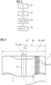
Nachfolgend wird in Verbindung mit den
Es ist entsprechend
Der Ort der äußersten Windung 15 entspricht dem Anfang des Metallbandes 4. Der Wert der Konturlinie KL an dieser Stelle entspricht dem Versatz vordersten Abschnitts i=1 des Metallbandes 4. Der Radius r für die nächstinnere Windung 15 kann ohne weiteres durch Subtrahieren der Dicke d des Metallbandes 4 vom Radius r ermittelt werden. An dieser Stelle des Metallbandes 4 kann die Konturlinie KL von der Steuereinrichtung 8 erneut ausgewertet werden. Diese Vorgehensweise kann nach und nach für alle Windungen 15 des Metallbandes 4 wiederholt werden. Somit kann die Steuereinrichtung 8 in einem Schritt S12 nach und nach für alle Windungen 15 und damit für Stützstellen, die um einen Abstand von 2nr (wobei der aktuelle Coilradius r variabel ist) voneinander beabstandet sind, jeweils den seitlichen Versatz des Metallbandes 4 an dieser Stelle ermitteln. Somit ergibt sich ein funktionaler Verlauf für den seitlichen Versatz des Metallbandes 4 über die gesamte Länge des Metallbandes 4. Anhand dieses Versatzes kann ohne weiteres der seitliche Versatz V für die Abschnitte i ermittelt werden.The location of the
Im einfachsten Fall sind die Abschnitte i durch die Stützstellen bestimmt. In diesem Fall sind die Abschnitte i nicht gleich groß. Falls die Abschnitte i gleich groß sein sollen oder einem anderen Kriterium genügen sollen, kann nach Bedarf eine Interpolation zwischen benachbarten Stützstellen erfolgen.In the simplest case, the sections i are determined by the support points. In this case, the sections i are not the same size. If the sections i should be the same size or should meet a different criterion, interpolation between neighboring support points can be carried out as required.
Die Schritte S11 und S12 entsprechend somit einer möglichen Implementierung der Schritte S1 und S2 von
Nachfolgend wird in Verbindung mit den
Es ist entsprechend
Die Schritte S21 bis S23 entsprechend somit einer weiteren möglichen Implementierung der Schritte S1 und S2 von
Die vorliegende Erfindung weist viele Vorteile auf. Durch die Erfassung der Kontur K einer Stirnseite 11 steht auf einfache Weise die Information für den seitlichen Versatz V der Abschnitte i über die gesamte Länge des Metallbandes 4 zur Verfügung. Dadurch können insbesondere überlegene Regelalgorithmen implementiert werden. Durch die Erfassung direkt am Abhaspel 2 erfolgt eine eigenständige Erfassung, die nicht auf externen Eingaben beruht. Weiterhin ist gewährleistet, dass Effekte, die vor dem Abhaspeln auftreten, zuverlässig erkannt und berücksichtigt werden. Die erfindungsgemäßen Lösungen sind einfach, robust und zuverlässig und können weiterhin auch bei bestehenden Walzanlagen nachgerüstet werden.The present invention has many advantages. By detecting the contour K of an
Obwohl die Erfindung im Detail durch das bevorzugte Ausführungsbeispiel näher illustriert und beschrieben wurde, so ist die Erfindung nicht durch die offenbarten Beispiele eingeschränkt und andere Varianten können vom Fachmann hieraus abgeleitet werden, ohne den Schutzumfang der Erfindung zu verlassen.Although the invention has been illustrated and described in detail by the preferred embodiment, the invention is not limited by the examples disclosed and other variations may be derived therefrom by those skilled in the art without departing from the scope of the invention.
- 11
- WalzgerüstRoll stand
- 22
- AbhaspelUncoiler
- 33
- CoilCoil
- 44
- Metallbandmetal band
- 55
- Aufhaspelreel
- 66
- weitere Walzgerüstefurther rolling stands
- 77
- S-RollensatzS roller set
- 88th
- SteuereinrichtungControl device
- 99
- SteuerprogrammTax program
- 1010
- MaschinencodeMachine code
- 1111
- StirnseitenEnd faces
- 1212
- Stellgliedactuator
- 1313
- ErfassungseinrichtungDetection device
- 1414
- CoilaugeCoil eye
- 1515
- Windungenconvolutions
- CC
- Stellgrößemanipulated variable
- D1, D2D1, D2
- Durchmesserdiameter
- dd
- BanddickeBand thickness
- ii
- Abschnitte des MetallbandsSections of metal strip
- KK
- Konturcontour
- KFKF
- Konturflächecontour surface
- KLKL
- Konturliniecontour line
- R1, R2, rR1, R2, r
- Radienradii
- S1 bis S23S1 to S23
- Schrittesteps
- Vv
- Versatzoffset
Claims (11)
dass der Steuereinrichtung (8) vor dem Abhaspeln des Metallbandes (4) eine Kontur (K) mindestens einer Stirnseite (11) des Coils (3) bekannt wird und dass die Steuereinrichtung (8) den jeweiligen seitlichen Versatz (V) unter Verwertung der Kontur (K) ermittelt.Operating method for a rolling mill which has at least one roll stand (1) and a decoiler (2) arranged upstream of the roll stand (1),
that the control device (8) becomes aware of a contour (K) of at least one end face (11) of the coil (3) before the metal strip (4) is uncoiled and that the control device (8) determines the respective lateral offset (V) using the contour (K) determined.
dadurch gekennzeichnet,
dass die Kontur (K) der Stirnseite (11) mittels einer dem Abhaspel (2) zugeordneten Erfassungseinrichtung (13) erfasst wird, während sich das Coil (3) bereits in dem Abhaspel (2) befindet, und sodann der Steuereinrichtung (8) zugeführt wird.Operating method according to claim 1,
characterized,
that the contour (K) of the end face (11) is detected by means of a detection device (13) assigned to the uncoiler (2), while the coil (3) is already in the uncoiler (2), and then fed to the control device (8). becomes.
dadurch gekennzeichnet,
characterized,
dadurch gekennzeichnet,
dass das Metallband (4) in dem Walzgerüst (1) kalt oder warm gewalzt wird.Operating method according to claim 1, 2 or 3,
characterized,
that the metal strip (4) is rolled cold or hot in the rolling stand (1).
dadurch gekennzeichnet,
dass die Abarbeitung des Maschinencodes (10) durch die Steuereinrichtung (8) bewirkt, dass die Steuereinrichtung (8) die Kontur (K) der Stirnseite (11) von einer dem Abhaspel (2) zugeordneten Erfassungseinrichtung (13) entgegennimmt, während sich das Coil (3) bereits in dem Abhaspel (2) befindet.Control program according to claim 5,
characterized,
that the processing of the machine code (10) by the control device (8) causes the control device (8) to receive the contour (K) of the end face (11) from a detection device (13) assigned to the unwinder (2) while the coil (3) is already in the uncoiler (2).
dadurch gekennzeichnet,
dass die Abarbeitung des Maschinencodes (10) durch die Steuereinrichtung (8) bewirkt,
characterized,
that the processing of the machine code (10) by the control device (8) causes
dadurch gekennzeichnet,
dass die Steuereinrichtung (8) als Steuereinrichtung nach Anspruch 8 ausgebildet ist.Rolling plant, which has at least one roll stand (1), a decoiler (2) arranged upstream of the roll stand (1) and a control device (8) for the roll stand (1),
characterized,
that the control device (8) is designed as a control device according to claim 8.
dadurch gekennzeichnet,
dass dem Abhaspel (2) eine Erfassungseinrichtung (13) zugeordnet ist, mittels derer die Kontur (K) der Stirnseite (11) erfasst wird, während sich das Coil (3) bereits in dem Abhaspel (2) befindet, und sodann der Steuereinrichtung (8) zugeführt wird.Rolling plant according to claim 9,
characterized,
that the uncoiler (2) is assigned a detection device (13), by means of which the contour (K) of the end face (11) is detected while the coil (3) is already in the uncoiler (2), and then the control device ( 8) is supplied.
dadurch gekennzeichnet,
dass das Walzgerüst (1) als Warmwalzgerüst ausgebildet ist, insbesondere die Walzanlage als Steckelmill ausgebildet ist, oder dass das Walzgerüst (1) als Kaltwalzgerüst ausgebildet ist, insbesondere als vorderstes Walzgerüst einer mehrgerüstigen Tandemstraße.Rolling plant according to claim 9 or 10,
characterized,
that the rolling stand (1) is designed as a hot rolling stand, in particular the rolling mill is designed as a Steckelmill, or that the rolling stand (1) is designed as a cold rolling stand, in particular as the frontmost rolling stand of a multi-stand tandem train.
Priority Applications (2)
| Application Number | Priority Date | Filing Date | Title |
|---|---|---|---|
| EP22171781.2A EP4272884A1 (en) | 2022-05-05 | 2022-05-05 | Determination of the lateral offset of a metal strip on the basis of the contour of a side face of the coil |
| PCT/EP2023/061013 WO2023213658A1 (en) | 2022-05-05 | 2023-04-26 | Determining the lateral offset of a metal strip on the basis of the contour of an end face of a coil |
Applications Claiming Priority (1)
| Application Number | Priority Date | Filing Date | Title |
|---|---|---|---|
| EP22171781.2A EP4272884A1 (en) | 2022-05-05 | 2022-05-05 | Determination of the lateral offset of a metal strip on the basis of the contour of a side face of the coil |
Publications (1)
| Publication Number | Publication Date |
|---|---|
| EP4272884A1 true EP4272884A1 (en) | 2023-11-08 |
Family
ID=81581093
Family Applications (1)
| Application Number | Title | Priority Date | Filing Date |
|---|---|---|---|
| EP22171781.2A Pending EP4272884A1 (en) | 2022-05-05 | 2022-05-05 | Determination of the lateral offset of a metal strip on the basis of the contour of a side face of the coil |
Country Status (2)
| Country | Link |
|---|---|
| EP (1) | EP4272884A1 (en) |
| WO (1) | WO2023213658A1 (en) |
Citations (5)
| Publication number | Priority date | Publication date | Assignee | Title |
|---|---|---|---|---|
| DE3413269C2 (en) | 1983-04-12 | 1991-11-14 | Ishikawajima-Harima Jukogyo K.K., Tokio/Tokyo, Jp | |
| JPH08231097A (en) * | 1995-02-23 | 1996-09-10 | Furukawa Electric Co Ltd:The | Detecting method for disordered rolling of thin plate rolling coil and its device |
| DE102009010355A1 (en) * | 2009-02-25 | 2010-09-02 | Solving 3D Gmbh | Profile logging device for logging surface profile of steel sheet coils, has stereo camera arrangements, where one of arrangements is arranged such that other arrangement detects surface areas of object |
| EP3202502A1 (en) | 2016-02-04 | 2017-08-09 | Primetals Technologies Germany GmbH | Strip position control |
| KR102348501B1 (en) * | 2020-05-21 | 2022-01-06 | 주식회사 포스코 | Apparatus for controlling charging coil |
-
2022
- 2022-05-05 EP EP22171781.2A patent/EP4272884A1/en active Pending
-
2023
- 2023-04-26 WO PCT/EP2023/061013 patent/WO2023213658A1/en unknown
Patent Citations (5)
| Publication number | Priority date | Publication date | Assignee | Title |
|---|---|---|---|---|
| DE3413269C2 (en) | 1983-04-12 | 1991-11-14 | Ishikawajima-Harima Jukogyo K.K., Tokio/Tokyo, Jp | |
| JPH08231097A (en) * | 1995-02-23 | 1996-09-10 | Furukawa Electric Co Ltd:The | Detecting method for disordered rolling of thin plate rolling coil and its device |
| DE102009010355A1 (en) * | 2009-02-25 | 2010-09-02 | Solving 3D Gmbh | Profile logging device for logging surface profile of steel sheet coils, has stereo camera arrangements, where one of arrangements is arranged such that other arrangement detects surface areas of object |
| EP3202502A1 (en) | 2016-02-04 | 2017-08-09 | Primetals Technologies Germany GmbH | Strip position control |
| KR102348501B1 (en) * | 2020-05-21 | 2022-01-06 | 주식회사 포스코 | Apparatus for controlling charging coil |
Also Published As
| Publication number | Publication date |
|---|---|
| WO2023213658A1 (en) | 2023-11-09 |
Similar Documents
| Publication | Publication Date | Title |
|---|---|---|
| DE4129988C2 (en) | Method for controlling the lateral position of a strip that runs out of a hot rolling mill and is to be rolled up | |
| EP1781429B1 (en) | Method for straightening a metal strip and straightening machine | |
| EP2195127B1 (en) | Operating method for introducing a product to be rolled into a roll stand of a roll mill, control device, data carrier, and roll mill for rolling a strip-type product to be rolled | |
| EP2588257B1 (en) | Operating method for a roller mill for rolling flat rolled goods having roller wear prediction | |
| WO2017133814A1 (en) | Model predictive strip position controller | |
| EP2697001B1 (en) | Control method for a rolling train | |
| EP3210681B1 (en) | Device and method for rolling a strip of material with variable thickness | |
| EP2697002B1 (en) | Control method for a mill train | |
| DE60016999T2 (en) | Method and device for regulating the strip shape during strip rolling | |
| EP3120943B1 (en) | Method for providing a length related material sheet data set for a coiled sheet of material | |
| DE102014215397B4 (en) | Band position control with optimized controller design | |
| DE69913538T2 (en) | Method and device for flatness control | |
| DE3240602C2 (en) | ||
| EP4272884A1 (en) | Determination of the lateral offset of a metal strip on the basis of the contour of a side face of the coil | |
| EP3720623B1 (en) | Stretching-bending-straightening system and method for the actuation thereof | |
| EP3691803B1 (en) | Multi-flexible rolling mill | |
| EP3691806B1 (en) | Flatness control with optimiser | |
| EP3823771B1 (en) | Method for ascertaining control variables for active profile and flatness control elements for a rolling stand and profile and average flatness values for hot-rolled metal strip | |
| EP3851217B1 (en) | Improved roll model adaptation | |
| EP3715000B1 (en) | Prevention of waves in the rolling of metal strips | |
| DE10159608B4 (en) | Rolling process for a band with a weld | |
| EP3936248B1 (en) | Rolling taking into account frequency behaviour | |
| DE102022211278B3 (en) | Method and computer program for adjusting the target thickness value for regulating the thickness of a strip to be newly rolled for at least one rolling stand | |
| DE1527612B2 (en) | DEVICE FOR REGULATING THE THICKNESS AND SECTIONAL SHAPE OR FLATNESS OF SHEET METALS AND STRIPS IN ROLLING MILLS | |
| EP4353375A1 (en) | Method for determining actuated variables of a roll stand, corresponding control program, control device with such control program, and rolling stand with such control device |
Legal Events
| Date | Code | Title | Description |
|---|---|---|---|
| PUAI | Public reference made under article 153(3) epc to a published international application that has entered the european phase |
Free format text: ORIGINAL CODE: 0009012 |
|
| STAA | Information on the status of an ep patent application or granted ep patent |
Free format text: STATUS: THE APPLICATION HAS BEEN PUBLISHED |
|
| AK | Designated contracting states |
Kind code of ref document: A1 Designated state(s): AL AT BE BG CH CY CZ DE DK EE ES FI FR GB GR HR HU IE IS IT LI LT LU LV MC MK MT NL NO PL PT RO RS SE SI SK SM TR |