EP4272876B1 - Beschichtungssystem für einen arbeitsdraht eines sensors - Google Patents
Beschichtungssystem für einen arbeitsdraht eines sensors Download PDFInfo
- Publication number
- EP4272876B1 EP4272876B1 EP23167553.9A EP23167553A EP4272876B1 EP 4272876 B1 EP4272876 B1 EP 4272876B1 EP 23167553 A EP23167553 A EP 23167553A EP 4272876 B1 EP4272876 B1 EP 4272876B1
- Authority
- EP
- European Patent Office
- Prior art keywords
- wire
- ring
- platform
- dipping
- coating
- Prior art date
- Legal status (The legal status is an assumption and is not a legal conclusion. Google has not performed a legal analysis and makes no representation as to the accuracy of the status listed.)
- Active
Links
Images








Classifications
-
- B—PERFORMING OPERATIONS; TRANSPORTING
- B05—SPRAYING OR ATOMISING IN GENERAL; APPLYING FLUENT MATERIALS TO SURFACES, IN GENERAL
- B05C—APPARATUS FOR APPLYING FLUENT MATERIALS TO SURFACES, IN GENERAL
- B05C3/00—Apparatus in which the work is brought into contact with a bulk quantity of liquid or other fluent material
- B05C3/02—Apparatus in which the work is brought into contact with a bulk quantity of liquid or other fluent material the work being immersed in the liquid or other fluent material
- B05C3/12—Apparatus in which the work is brought into contact with a bulk quantity of liquid or other fluent material the work being immersed in the liquid or other fluent material for treating work of indefinite length
- B05C3/125—Apparatus in which the work is brought into contact with a bulk quantity of liquid or other fluent material the work being immersed in the liquid or other fluent material for treating work of indefinite length the work being a web, band, strip or the like
-
- B—PERFORMING OPERATIONS; TRANSPORTING
- B05—SPRAYING OR ATOMISING IN GENERAL; APPLYING FLUENT MATERIALS TO SURFACES, IN GENERAL
- B05C—APPARATUS FOR APPLYING FLUENT MATERIALS TO SURFACES, IN GENERAL
- B05C13/00—Means for manipulating or holding work, e.g. for separate articles
- B05C13/02—Means for manipulating or holding work, e.g. for separate articles for particular articles
-
- B—PERFORMING OPERATIONS; TRANSPORTING
- B05—SPRAYING OR ATOMISING IN GENERAL; APPLYING FLUENT MATERIALS TO SURFACES, IN GENERAL
- B05C—APPARATUS FOR APPLYING FLUENT MATERIALS TO SURFACES, IN GENERAL
- B05C15/00—Enclosures for apparatus; Booths
-
- B—PERFORMING OPERATIONS; TRANSPORTING
- B05—SPRAYING OR ATOMISING IN GENERAL; APPLYING FLUENT MATERIALS TO SURFACES, IN GENERAL
- B05C—APPARATUS FOR APPLYING FLUENT MATERIALS TO SURFACES, IN GENERAL
- B05C3/00—Apparatus in which the work is brought into contact with a bulk quantity of liquid or other fluent material
- B05C3/02—Apparatus in which the work is brought into contact with a bulk quantity of liquid or other fluent material the work being immersed in the liquid or other fluent material
- B05C3/09—Apparatus in which the work is brought into contact with a bulk quantity of liquid or other fluent material the work being immersed in the liquid or other fluent material for treating separate articles
- B05C3/10—Apparatus in which the work is brought into contact with a bulk quantity of liquid or other fluent material the work being immersed in the liquid or other fluent material for treating separate articles the articles being moved through the liquid or other fluent material
-
- B—PERFORMING OPERATIONS; TRANSPORTING
- B05—SPRAYING OR ATOMISING IN GENERAL; APPLYING FLUENT MATERIALS TO SURFACES, IN GENERAL
- B05C—APPARATUS FOR APPLYING FLUENT MATERIALS TO SURFACES, IN GENERAL
- B05C9/00—Apparatus or plant for applying liquid or other fluent material to surfaces by means not covered by any preceding group, or in which the means of applying the liquid or other fluent material is not important
- B05C9/02—Apparatus or plant for applying liquid or other fluent material to surfaces by means not covered by any preceding group, or in which the means of applying the liquid or other fluent material is not important for applying liquid or other fluent material to surfaces by single means not covered by groups B05C1/00 - B05C7/00, whether or not also using other means
Definitions
- Medical patients often have diseases or conditions that require the measurement and reporting of biological conditions. For example, if a patient has diabetes, it is important that the patient have an accurate understanding of the level of glucose in their system.
- diabetes patients have monitored their glucose levels by sticking their finger with a small lance, allowing a drop of blood to form, and then dipping a test strip into the blood.
- the test strip is positioned in a handheld monitor that performs an analysis on the blood and visually reports the measured glucose level to the patient. Based upon this reported level, the patient makes important decisions on what food to consume, or how much insulin to inject.
- the patient may eat improperly or inject either too much or too little insulin. Either way, the patient has a reduced quality of life and increased chance of doing permanent damage to their health and body. Diabetes is a devastating disease that if not properly controlled can lead to detrimental physiological conditions such as kidney failure, skin ulcers, bleeding in the eyes and eventually blindness, and pain and the eventual amputation of limbs.
- a single glucose measurement provides only a snapshot of the instantaneous level in a patient's body. Such a single measurement provides little information about how the patient's use of glucose is changing over time, or how the patient reacts to specific dosages of insulin. Even a patient that is adhering to a strict schedule of strip testing will likely be making incorrect decisions as to diet, exercise, and insulin injection. This is exacerbated by a patient that is less consistent on their strip testing. To give the patient a more complete understanding of their diabetic condition and to get a better therapeutic result, some diabetic patients are now using continuous glucose monitoring.
- Electrochemical glucose sensors operate by using electrodes which typically detect an amperometric signal caused by oxidation of enzymes during conversion of glucose to gluconolactone. The amperometric signal can then be correlated to a glucose concentration.
- Two-electrode (also referred to as two-pole) designs use a working electrode and a reference electrode, where the reference electrode provides a reference against which the working electrode is biased. The reference electrodes effectively complete the electron flow in the electrochemical circuit.
- Three-electrode (or three-pole) designs have a working electrode, a reference electrode, and a counter electrode. The counter electrode replenishes ionic loss at the reference electrode and is part of the ionic circuit.
- Document CN 202 667 079 U discloses a semi automatic coating controlling machine which has automatic film feeding system that is provided with a vertical base plate which is provided with a vertical plate for coating needles or pins.
- an apparatus for coating a working wire of a sensor includes a carousel, a robotic arm, and an optical scanner.
- the carousel includes a first platform, a second platform, and a ring dipping tool.
- the first platform has a central axis, the first platform supporting a plurality of stations, all arranged around the central axis.
- the second platform is positioned above the first platform, with a platform actuator that raises, lowers, and rotates the second platform with respect to the first platform.
- the ring dipping tool is coupled to an edge of the second platform, the ring dipping tool being oriented vertically with respect to ground, and extending toward the first platform.
- the robotic arm is configured to transport a fixture to the carousel, the fixture being configured to hold the working wire.
- the optical scanner is positioned near a wire dipping station of the plurality of stations and configured to scan a position of the working wire and a location of the ring dipping tool.
- an apparatus for coating a working wire of a sensor includes a ring dipping tool having a ring and a shaft, the shaft is oriented vertically with respect to ground.
- a robotic arm is configured to transport the working wire.
- An optical scanner is in communication with the robotic arm and configured to scan a position of the working wire and a location of the ring dipping tool.
- a wire dipping station has a container configured to hold a coating solution, and a coating station actuator is configured to move the ring dipping tool into the container. The robotic arm uses the position of the working wire and the location of the ring dipping tool to insert the working wire through the ring of the ring dipping tool.
- Embodiments disclose systems and processes for manufacturing working wires for sensor, such as a continuous biological sensor, where the embodiments reduce cost and improve accuracy and efficiency compared to known art.
- the continuous biological sensor may be, for example, a continuous glucose monitor, in which the working wire includes an enzyme layer to detect the level of glucose in a patient's blood.
- the biological sensor can be a metabolic sensor for measuring other metabolic characteristics such as ketones, lactates or fatty acids.
- the sensor uses a working wire (i.e., electrode for the sensor) that has a core and several concentrically formed membrane layers.
- a coating system uses ring dipping for coating working wires.
- the ring dipping involves holding the working wire horizontally and inserting it through a ring of a dipping tool, where the ring is oriented vertically.
- the coating system includes multiple stations mounted in a carousel, beneficially enabling the ring dipping to be performed continuously in an automated manner and enabling multiple working wires to be processed in an efficient manner.
- the stations can include a wire dipping station and various stations for the ring dipping tool, such as a cleaning station, a drying station, and a coating station to reapply coating solution to the tool.
- the coating system uniquely includes an optical scanner that scans the position of the working wire and the ring dipping tool such that the working wire can accurately be inserted through the ring.
- Embodiments include an automated measurement tool that measures layer thicknesses of coatings on the working wires after each dip. The measurements are used as feedback for the coating system to adjust dipping parameters such as insertion and withdrawal speed of the working wire through the ring dipping tool, and/or an amount of coating film to be placed on the ring dipping tool.
- the coating system may be configured to enable multiple fixtures to be processed in parallel, where each fixture has one or more working wires.
- the coating systems and methods of the present disclosure provide improved accuracy and increased throughput compared to conventional techniques.
- the automated system measures dimensions of working wires while they are progressing through a dipping process and uses the measurements to adjust dipping parameters in real-time.
- the measurement system can take multiple measurements along a length of the working wires and can also measure multiples wires that are mounted in a fixture. By providing thorough monitoring of coating thicknesses and by doing so in real-time, more efficient and accurate dip coating of working wires is achieved compared to conventional methods.
- the systems and methods may optimize the manufacturing process, such as by reducing (e.g., minimizing) the number of dips required to achieve a desired coating thickness.
- scanning of the working wire position and ring dipping tool enables the robotic arm to account for positional variances that may occur from wire to wire and/or for non-straightness of an individual wire (e.g., a wire sagging toward its end that is not held by the fixture). The scanning thus improves the accuracy in centering the wire as it is being moved through the ring dipping tool.
- Embodiments may also include an environmental chamber for housing the coating system, where the chamber provides highly accurate environmental conditions throughout the chamber.
- the chamber includes individually controlled fans that can adjust airflow based on humidity sensor feedback from a local region in the chamber.
- a recirculation path within the chamber along with customizable vent plates enable uniform air flow to be created in the chamber.
- Ports for dry gas and ambient air are provided, where valves are adjusted based on feedback from humidity sensors to enable relative humidity levels in the chamber to be controlled in a highly accurate manner.
- the working wire 100 is an elongated wire having a circular cross-section. It will be understood that other cross-sections may be used, such as square, rectangular, triangular, or other geometric shapes. Furthermore, the working wire 100 may take other forms, such as a plate or ribbon.
- the working wire may be used as a working electrode of a continuous biological sensor, such as a working electrode of a continuous glucose monitor.
- the working wire 100 has a substrate 110 onto which biological membranes 120 may be disposed.
- the types of biological membranes that may be manufactured by the present methods and systems will not be described herein, but may include biological membranes that are well-known and other types of coating layers on working wires for biological sensors.
- the biological membranes 120 include an interference membrane 121 (which may also be referred to as an interference layer) on the substrate 110, an enzyme membrane 122 (i.e., enzyme layer) on the interference membrane 121, and a glucose limiting membrane 123 (i.e., glucose limiting layer) on the enzyme membrane 122.
- a protective or outer coating may be optionally applied over the glucose limiting membrane 123.
- the working wire 100 is illustrated as having three membranes 120, it will be understood that the membranes 120 may be more or fewer in number.
- the electrons are drawn into the platinum by a bias voltage placed across the platinum wire and a reference electrode.
- the magnitude of the electrical current flowing in the platinum is intended to be related to the number of hydrogen peroxide reactions, which in turn is proportional to the number of glucose molecules oxidized.
- a measurement of the electrical current on the platinum wire can thereby be associated with a particular level of glucose in the patient's blood or interstitial fluid (ISF).
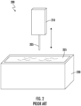
- FIG. 2 is a schematic of a dipping system, as known in the art.
- An isometric view of a dipping station 200 for one type of coating process known in the art is shown, where the parts (e.g., wires 205) to be coated are lowered vertically into a tub 220 of coating solution 225.
- Dipping station 200 is shown with a fixture 210 and the tub 220 with the coating solution 225.
- One or more wires 205 may be mounted into the fixture 210, where the fixture 210 is depicted as a block for simplicity.
- the fixture 210 is used for transporting the wires 205 through a dipping process during manufacturing.
- the fixture 210 may also be referred to as a holder or tray.
- FIGS. 5A-5B are isometric views of a coating system 500, in accordance with some embodiments.
- Coating system 500 is an apparatus for coating a wire 105 of a sensor, and includes a carousel 505, a robotic arm 510, and a scanner such as an optical scanner 515.
- the wire 105 or wires 105 are work-in-progress (“WIP") wires 550 (as shown in FIGS. 7A-7B and 9 ) being processed by the coating system 500.
- WIP work-in-progress
- the controller 545 may be a computer hardware processor (see processor 1405 in FIG. 14 ) that is separate from and connected to the coating system 500, such as to the robotic arm 510, either physically (e.g., hard-wired), or wirelessly.
- the controller 545 may comprise one or more processors incorporated into the robotic arm 510 and/or other components of the coating system 500 such as the carousel 505, optical scanner 515 and measurement station 535.
- the WIP wires 550 being processed by the coating system 500 may have some or none of the membrane layers applied as the WIP wires 550 pass through a plurality of carousel stations 555 on the carousel 505.
- the cassette area 520 serves as a rack for holding fixtures 530 containing the WIP wires 550.
- the fixtures 530 are pre-loaded in the cassette 520a, 520b or 520c and advanced to the front 560 of the cassette area 520, to be picked up by the robotic arm 510 and processed through the coating system 500.
- One cassette 520a, 520b or 520c of the cassette area 520 can be empty initially, for placing fixtures 530 into after the WIP wires 550 have been fully completed.
- the holding area 525 (see FIG. 5B ) may be used to temporarily store fixtures 530 with partially coated WIP wires 550 (i.e., some layers have been dipped but more layers need to be added) while the fixtures 530 are waiting to be moved or processed at the next station of the plurality of carousel stations 555.
- a plurality of ring dipping tools 300 may be coupled to the edge of the second platform 610 and spaced apart from each other at locations corresponding to the coating station 555d, the wire dipping station 555a, the cleaning station 555b and 555e, and the drying station 555c (i.e., five ring dipping tools 300, since there are two cleaning stations 555b and 555e in this embodiment).
- the first platform 605 remains fixed in position, and the second platform 610 rotates with respect to the first platform 605.
- the second platform 610 is lifted from a nominal height (i.e., baseline distance from the first platform 605) before rotating so that each ring dipping tool 300 can be clear from colliding with any of the containers of the carousel stations 555 (such as first and second cleaning containers 635 and 640) before being moved to the next station.
- the second platform 610 is then lowered back to its nominal height when the ring dipping tools 300 have been positioned at the next station.
- a clean ring dipping tool 300 begins at the coating station, 555d where a coating station actuator 650 is fixedly positioned opposite the coating station 555d.
- a decoupler 655 is attached to the center axis 625 and faces toward the coating station 555d.
- the linear stages 645 holding the ring dipping tools 300 are normally fixed relative to the second platform 610, when a linear stage 645 is at the coating station 555d, the decoupler 655 unlocks the linear stage 645.
- the coating station actuator 650 is connectable to the linear stage 645 to move (e.g., lower) the ring dipping tool 300 into the first coating container 660 of the coating station 555d when the linear stage 645 is unlocked.
- the first coating container 660 holds a coating solution 315 to be applied to the ring dipping tool 300, for creating a layer on the WIP wires 550.
- WIP wires 550 such as 550a, 550b, 550c and 550d, are shown in this embodiment, but the fixture 530a may be configured to hold more or fewer WIP wires 550 in other embodiments.
- the WIP wires 550 are mounted in a single row in this embodiment, spaced apart from each other so that each one can be measured individually from various angles. In other embodiments the WIP wires 550 may be arranged in other fashions such as in more than one row, aligned or staggered from each other, so long as sufficient space is between the wires to enable each WIP wire 550 to be measured separately.
- This cycle is repeated for WIP wire 550c and WIP wire 550d.
- the first fixture 530a can be moved to another area for further processing, such as to be measured, cured, or unloading if the full membrane has been completed.
- the cleaning should occur because the coating solution 315 cures on the ring 310 during the dipping process, leaving a residue.
- the ring 310 should be cleaned after each dip because residual coating solution 315 will affect how the next film 320 is formed on the ring 310, which can then impact how the coating is laid onto the WIP wire 550. If more than one cleaning station is present, a subsequent immersion of the ring dipping tool 300 into a cleaning liquid is performed at the next cleaning station such as cleaning station 555e. Finally, the ring dipping tool 300 is dried at the drying station 555c, and then moved to the coating station 555d to begin the cycle again.
- the WIP wires 550 are being dipped at the wire dipping station 555a.
- the next wire on the first fixture 530a can be moved into place for dipping.
- the robotic arm 510 moves WIP wire 550b into proper position (as shall be described for FIG. 8 ) relative to the ring dipping tool 300.
- WIP wire 550c is dipped when the next ring dipping tool 300 is rotated, and finally WIP wire 550d.
- the robotic arm 510 can move the first fixture 530a to the holding area 525 to cure.
- the robotic arm 510 can then pick up a second fixture 530b for processing by the carousel 505.
- the robotic arm 510 can move the first fixture 530a to a measurement station 535 (as shall be described for FIG. 9 ) to determine if dipping parameters need to be adjusted before the next layer of coating is applied to the wires on fixture 530a. If more layers are needed, the first fixture 530a can be returned to the carousel 505 while the second fixture 530b is curing.
- the robotic arm 510 can move the first fixture 530a to the cassette area 520.
- a single robot moves multiple fixtures 530 through the coating system 500.
- more than one robot can be included in the system to perform parallel handling of multiple wire fixtures 530.
- the optical scanner 515 is in communication with the robotic arm 510, via the controller 545, such that the robotic arm 510 uses the position of the WIP wire 550a and the location of the ring dipping tool 300 while inserting the WIP wire 550a through the ring dipping tool 300 at the wire dipping station 555a.
- the optical scanner 515 may provide the lengthwise profile of the WIP wire 550a to the controller 545, which controls the robotic arm 510 so that the robotic arm 510 can appropriately direct the WIP wire 550a through the ring 310 as the WIP wire 550a is advanced and withdrawn.
- the robotic arm 510 inserts the WIP wire 550a into the ring 310 on a path that is perpendicular to the plane of the ring 310, adjusting the robotic arm's trajectory to compensate for the information about the lengthwise profile of the WIP wire 550a (e.g., variances due to bending from gravity and/or variance in the innate straightness of the WIP wire 550a) and the ring 310 position provided by the optical scanner 515.
- the inserting of the WIP wire 550a relative to the ring 310, based on the scanned positions, can be highly accurate, such as up to 5 microns of a target position.
- the optical scanner 515 also scans the ring 310 so that the robotic tool can account for any changes in orientation of the ring 310 between cycles with respect to the WIP wire 550a. Inclusion of the optical scanner 515 at the wire dipping station 555a, to properly move the WIP wire 550a through the ring dipping tool 300, provides high accuracy of the layers being deposited onto the WIP wire 550a.
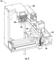
- FIG. 9 shows a close-up view of the measurement station 535 from FIG. 5B , in accordance with some embodiments.
- the measurement station 535 may be an automated measurement system in communication with the coating station actuator 650, via the controller 545 (as shown in FIG 5A ). Measurements of coating thicknesses on the WIP wire 550a, taken by the automated measurement system, provide feedback to the controller 545 for controlling the coating station actuator 650.
- the automated measurement system can also provide feedback of layer thicknesses to the controller 545, to control the wire dipping station 555a. This closed-loop feedback can be used to alter parameters for the next layer to be dipped onto the WIP wires 550 so that the overall membrane can be precisely built to the desired thickness.
- the insertion or withdrawal speeds of the WIP wire 550a through the ring 310 can be altered to apply a thinner or thicker layer on the WIP wire 550a during the next cycle.
- immersion or withdrawal speeds of the ring dipping tool 300 into the coating solution 315 can be adjusted to create a thinner or thicker film 320 on the ring 310.
- the speeds and even the immersion depth of the ring dipping tool 300 in the coating solution 315 can affect the film thickness since solution can flow down from the shaft 305 into the ring 310 area.
- layer thicknesses of the WIP wire 550a can be controlled to a highly accurate level, such as within 1 to 3 microns of a target layer thickness.
- the thicknesses to be created can also be adjusted to achieve the desired membrane thickness within a maximum number of dips.
- the automated measurement system is an in-line optical measurement tool 900 (i.e., optical measurement tool 900 used during the manufacturing process), where the diameter of each WIP wire 550 is measured to derive a coating thickness that has accumulated from the last dipping cycle.
- the optical measurement tool 900 may be, for example, an optical micrometer that utilizes a laser beam to measure dimensions in a noncontact manner. The micrometer detects the size of the WIP wire 550 by measuring the shadow of the object that is within the path of the laser beam.
- the optical measurement tool 900 is mounted on a stage that has both linear and rotational actuators, which enables the optical measurement tool 900 to be moved so that it can measure the WIP wires 550 on the fixture 530 (e.g., the first fixture 530a in FIG. 8 ) from various angles and at various points along the length of the WIP wires 550.
- the robotic arm 510 may be utilized to move the first fixture 530a while the WIP wires 550 are being scanned by the optical measurement tool 900.
- each WIP wire 550 in the first fixture 530a may have its thickness measured along its entire length and at different angles around its entire circumference.
- each WIP wire 550 can be measured at 10 to 40 points along its length, and from three different angles at each point.
- FIG. 10 shows ring 310 designs that can be used to further customize how the layers are formed on the WIP wires 550a, in accordance with some embodiments.
- the side profiles 1001-1004 shown in FIG. 10 illustrate that in a plane perpendicular to the ring 310, the ring 310 can be curved (profile 1001), flat (profile 1002), inclined downward (profile 1003) or inclined upward (profile 1004). Because the coating solution 315 will flow toward the bottom of the ring 310 due to gravity, the different side profiles affect how that flow occurs. In turn, these side profiles will affect how the coating film 320 is deposited onto the WIP wire 550a, and thus the thickness of the layer that forms.
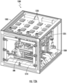
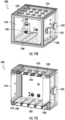
- FIGS. 12A-12B are isometric views of an environmental chamber with a coating system 500 inside, in accordance with some embodiments.
- the coating system 500 is housed in an environmental chamber 1200, to provide highly controlled environmental conditions during the dipping process.
- FIG. 12C shows an isometric view of the environmental chamber 1200 without the coating system 500 inside, in accordance with some embodiments.
- the environmental chamber 1200 provides highly accurate temperature, humidity, and airflow conditions for the coating system 500 through localized control of various parameters.
- an environmental chamber is filled with static air, and the humidity is decreased to the desired level by adding dry gas such as nitrogen.
- dry gas which is typically input from one location in the chamber, can create non-uniform conditions (e.g., relative humidity) throughout the chamber. Air mixing within the chamber can also be non-uniform, which creates or exacerbates any uneven conditions in the chamber.
- sensors typically have a delay in their response time. For example, readings from a relative humidity sensor may have a delay on the order of 30 seconds from the real-time conditions, which will then provide inaccurate readings for an environmental controller to respond to.
- Yet further difficulties are encountered for large chambers, such as having dimensions of several feet per side, in that whenever the chamber is opened, it can take a long time (e.g., at least 30 minutes) to re-establish the desired environmental conditions in the chamber.
- FIGS. 12A-12C show that the environmental chamber 1200 is formed by an outer enclosure 1205 with a door 1210 through which the interior of the environmental chamber 1200 can be accessed, such as for loading or removing WIP wires 550 for processing, or for maintaining the coating system 500.
- the outer enclosure 1205 may be a box, shell, container, or casing that forms the external boundaries of the environmental chamber 1200.
- the environmental chamber 1200 is illustrated as approximately a rectangular shape in this embodiment but other shapes may be used as needed for the manufacturing system.
- the environmental chamber 1200 of the present disclosure incorporates several unique features to provide extremely accurate and responsive environmental conditions.
- a controller 545 shown in FIG. 12C , is in communication with all these components to provide accurate and uniform conditions in the environmental chamber 1200 in a highly responsive manner.
- a first gas valve 1230 is on one side wall of the environmental chamber 1200.
- the first gas valve 1230 serves as an inlet for humid air, such as ambient air, to raise the relative humidity inside the environmental chamber 1200 when needed.
- the first gas valve 1230 may include an actuator 1235 that adjusts the amount that the first gas valve 1230 opens when ambient air is needed to be input.
- the first gas valve 1230 is coupled to the outer enclosure 1205, where the first gas valve 1230 is configured to adjust an amount of humidity-containing gas that enters the environmental chamber 1200.
- the first gas valve 1230 and actuator 1235 include a gate that controls the size of a port to allow ambient air into the environmental chamber 1200.
- the controller 545 causes the first gas valve 1230 to automatically open when a humidity level in the interior of the environmental chamber 1200 is lower than a desired setpoint.
- the degree to which the first gas valve 1230 opens is based on the change in humidity level needed.
- a dry gas port 1240 is shown in FIG. 12B , connectable to a dry gas source 1245 (e.g., pure, dry nitrogen having 0% moisture) by a dry gas valve 1250 and gas tubing 1255.
- the dry gas port 1240 is illustrated on the opposite wall as the first gas valve 1230 in this embodiment but may be coupled to a different wall of the environmental chamber 1200 in other embodiments.
- a first plurality of fans 1225 is shown in the upper area of the environmental chamber 1200, where the first plurality of fans 1225 are independently controlled from each other. This individualized control of the first plurality of fans 1225 enables localized air flow problems to be addressed, such as to counteract low flow in a particular region of the environmental chamber 1200 (e.g., "dead spots"). Sixteen fans 1225 are shown in this embodiment in a four-by-four array. In other embodiments, more or fewer fans may be utilized, arranged in other patterns or placed as needed based on air pathways created by the presence of the coating system 500 inside the environmental chamber 1200.
- a plurality of vent plates 1260 (shown in FIG. 12C ) is in a bottom area of the environmental chamber 1200, to enable air to recirculate through the environmental chamber 1200.
- the controller 545 is in communication with the first gas valve 1230, the dry gas valve 1250 and the first plurality of fans 1225.
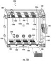
- FIGS. 13A-13C are various views showing a recirculation path of an environmental chamber 1200, in accordance with some embodiments.
- FIGS. 13A-13C show details of the environmental control features of the environmental chamber 1200.
- FIG. 13A is a side cutaway view
- FIG. 13B is an isometric view of the side and back of the environmental chamber 1200
- FIG. 13C is a cutaway view of FIG. 13B .
- a first wall 1305 is near a top surface of the outer enclosure 1205
- a second wall 1310 is near a lateral surface of the outer enclosure 1205
- a third wall 1315 is near a bottom surface of the outer enclosure 1205.
- the first plurality of fans 1225 blow air as indicated by arrows 1350a,1350b, 1350c, and 1350d toward the bottom of the environmental chamber 1200, where the air at the bottom of the environmental chamber 1200 passes through the vent plates 1260 as indicated by arrows 1352.
- the first plurality of fans 1225 is coupled to the first wall 1305 and faces an interior of the outer enclosure 1205. Each fan in the first plurality of fans 1225 is individually controllable by the controller 545.
- vent plates 1260 are coupled to the third wall 1315 and may be, for example, a mesh, a perforated sheet, or other types of plates having apertures.
- An example vent 1325 is shown in FIG. 13A , having staggered holes in this embodiment.
- the vents 1325 across the third wall 1315 may all be the same or may be customized for their particular location.
- vents 1325 may be configured with less open area (e.g., fewer holes or smaller holes) in locations where less airflow is desired, or more open area where more airflow is desired.
- a vent 1325 underneath a dense or low airflow area of the coating system 500 may be configured with higher open area than in other locations of the third wall 1315 in order to encourage airflow in that region.
- Embodiments include a plurality of humidity sensors 1330, where the controller 545 is in communication with the plurality of humidity sensors 1330 to individually control each fan in the first plurality of fans 1225 according to individual humidity sensors 1330 in the plurality of humidity sensors 1330.
- the humidity sensors 1330 can be positioned near key locations of the coating system 500, such as near the dry gas port 1240 or first gas valve 1230, the coating station 555d, wire dipping station 555a, holding area 525, and/or cassette area 520.
- humidity levels of 13-20% are desired in the environmental chamber 1200 to achieve fast flash of volatiles in the coating solution 315, while still having some humidity present.
- the controller 545 monitors humidity levels as well as rates of change in humidity sensed by the humidity sensors 1330. Monitoring a rate of change of humidity can even further improve the accuracy and responsiveness of the environmental chamber 1200, compared to monitoring humidity levels alone.
- Port connections 1340 in the environmental chamber 1200 allow cables from an external source to pass through into the environmental chamber 1200 for electrical connections, pneumatic connections, or the like.
- the environmental chamber 1200 reduces the time to reset the required environmental conditions compared to conventional systems, which reduces cycle time and labor costs. Because of the unique design of the environmental chamber 1200 involving features such as independently operating fans 1225, a recirculating flow path, configurable vent plates 1260 and localized feedback from sensors at various locations in the environmental chamber 1200, the environmental chamber 1200 provides a more uniform and accurate environment, and in a more responsive manner, than conventional systems.
- the various components of the system or method generally represent appropriate hardware and software components for providing the described resources and performing the described functions.
- the hardware generally includes any appropriate number and combination of computing devices, network communication devices, and peripheral components connected together, including various processors, computer memory (including transitory and non-transitory media), input/output devices, user interface devices, communication adapters, communication channels, etc.
- the software generally includes any appropriate number and combination of conventional and specially-developed software with computer-readable instructions stored by the computer memory in non-transitory computer-readable or machine-readable media and executed by the various processors to perform the functions described herein.
Landscapes
- Coating Apparatus (AREA)
- Length Measuring Devices By Optical Means (AREA)
- Wire Processing (AREA)
Claims (15)
- Vorrichtung zum Beschichten eines Arbeitsdrahtes (100) eines Sensors, wobei die Vorrichtung umfasst:
ein Karussell, umfassend:eine erste Plattform (605) mit einer Mittelachse (625), wobei die erste Plattform mehrere Stationen (555) trägt, die um die Mittelachse herum angeordnet sind;eine zweite Plattform (610), die über der ersten Plattform positioniert ist, mit einem Plattformaktuator (615), der die zweite Plattform in Bezug auf die erste Plattform anhebt, senkt und dreht;ein Ringtauchwerkzeug (300), das mit einer Kante der zweiten Plattform gekoppelt ist, wobei das Ringtauchwerkzeug vertikal zum Boden ausgerichtet ist und sich in Richtung der ersten Plattform erstreckt;einen Roboterarm (510), der konfiguriert ist, um eine Halterung (530) zum Karussell zu transportieren, wobei die Halterung zum Halten des Arbeitsdrahts konfiguriert ist; undEin optischer Scanner (515), der in der Nähe einer Drahttauchstation der Vielzahl von Stationen positioniert und konfiguriert ist, um eine Position des Arbeitsdrahts und eine Position des Ringtauchwerkzeugs zu scannen. - Vorrichtung nach Anspruch 1, wobei:das Ringtauchwerkzeug durch eine Linearstufe (645) mit dem Rand der zweiten Plattform gekoppelt ist;eine Beschichtungsstation der Vielzahl von Stationen einen ersten Behälter (660) umfasst, der konfiguriert ist, um eine Beschichtungslösung aufzunehmen; undDie Vorrichtung umfasst ferner einen Beschichtungsstationsaktor (650), der konfiguriert ist, um mit der Linearstufe verbunden zu werden, um das Ringtauchwerkzeug in den ersten Behälter zu bewegen.
- Vorrichtung nach Anspruch 2, ferner umfassend ein automatisiertes Messsystem (535) in Verbindung mit dem Beschichtungsstationsaktor, wobei Messungen von Beschichtungsdicken auf dem Arbeitsdraht, die von dem automatisierten Messsystem aufgenommen werden, eine Rückmeldung zur Steuerung des Beschichtungsstationsaktors bereitstellen.
- Vorrichtung nach einem der vorhergehenden Ansprüche, ferner umfassend ein automatisiertes Messsystem und einen Haltebereich (525), wobei der Roboterarm positioniert ist, um die Halterung zwischen dem Karussell, dem automatisierten Messsystem und dem Haltebereich zu transportieren.
- Vorrichtung nach einem der vorhergehenden Ansprüche, ferner umfassend ein Gaszufuhrrohr (1105), das mit dem Roboterarm gekoppelt ist, wobei ein Ende des Gaszufuhrrohrs in der Nähe eines Arbeitsendes des Roboterarms ist.
- Vorrichtung nach einem der vorhergehenden Ansprüche, wobei der optische Scanner mit dem Roboterarm in Verbindung steht, sodass der Roboterarm die Position des Arbeitsdrahts und die Position des Ringtauchwerkzeugs verwendet, um den Arbeitsdraht durch das Ringtauchwerkzeug an der Drahttauchstation der Vielzahl von Stationen einzuführen.
- Vorrichtung nach einem der vorhergehenden Ansprüche, wobei eine Reinigungsstation der Vielzahl von Stationen einen zweiten Behälter (635) umfasst, der konfiguriert ist, um ein Lösungsmittel aufzunehmen.
- Vorrichtung nach einem der vorhergehenden Ansprüche, wobei die Halterung konfiguriert ist, um eine Vielzahl von Arbeitsdrähten zu halten, wobei die Vielzahl von Arbeitsdrähten voneinander beabstandet sind.
- Vorrichtung nach Anspruch 8, ferner umfassend eine Steuerung (545) in Verbindung mit dem Roboterarm, wobei die Steuerung den Roboterarm bewegt und das Karussell so dreht, dass die Vielzahl von Arbeitsdrähten durch das Karussell bearbeitet wird.
- Vorrichtung nach einem der vorhergehenden Ansprüche, ferner umfassend eine Vielzahl von Ringtauchwerkzeugen, die mit dem Rand der zweiten Plattform gekoppelt sind und voneinander beabstandet an Orten sind, die jeder Station der Vielzahl von Stationen entsprechen.
- Vorrichtung nach einem der vorhergehenden Ansprüche, ferner umfassend eine Umgebungskammer (1200), umfassend:ein äußeres Gehäuse (1005);eine erste Wand (1305) in der Nähe einer oberen Oberfläche des äußeren Gehäuses, eine zweite Wand (1310) in der Nähe einer seitlichen Oberfläche des äußeren Gehäuses und eine dritte Wand (1315) in der Nähe einer unteren Oberfläche des äußeren Gehäuses, wobei die erste Wand, die zweite Wand und die dritte Wand miteinander verbunden und vom äußeren Gehäuse beabstandet sind, um einen Rückführweg zwischen dem äußeren Gehäuse und der ersten Wand, der zweiten Wand und der dritten Wand zu bilden;eine erste Vielzahl von Lüftern (1225), die mit der ersten Wand gekoppelt sind und einem Inneren des äußeren Gehäuses zugewandt sind;eine zweite Vielzahl von Lüftern (1320), die sich innerhalb des Rückführwegs befinden;eine Vielzahl von Entlüftungsplatten (1260), die mit der dritten Wand gekoppelt sind;ein erstes Gasventil (1230), das mit dem äußeren Gehäuse gekoppelt ist, wobei das erste Gasventil konfiguriert ist, um eine Menge von feuchtigkeitshaltigem Gas, das in die Umgebungskammer eintritt, einzustellen;ein Trockengasventil (1250), das mit dem äußeren Gehäuse gekoppelt ist; undeine Steuerung, die mit dem ersten Gasventil, dem Trockengasventil und der ersten Vielzahl von Lüftern in Verbindung steht, wobei jeder Lüfter der ersten Vielzahl von Lüftern konfiguriert ist, um von der Steuerung individuell gesteuert zu werden.
- Vorrichtung nach Anspruch 11, wobei die Umgebungskammer ferner eine Vielzahl von Feuchtigkeitssensoren, Sensoren (1330), umfasst, wobei die Steuerung mit der Vielzahl von Feuchtigkeitssensoren in Verbindung steht, um jeden Lüfter der ersten Vielzahl von Lüftern gemäß einzelnen Feuchtigkeitssensoren in der Vielzahl von Feuchtigkeitssensoren individuell zu steuern.
- Vorrichtung nach Anspruch 12, wobei die Steuerung eine Änderungsrate der Feuchtigkeit in der Umgebungskammer überwacht, die durch die Vielzahl von Feuchtigkeitssensoren erfasst wird.
- Vorrichtung nach einem der Ansprüche 11 bis 13, wobei die Steuerung bewirkt, dass das erste Gasventil öffnet, wenn ein Feuchtigkeitsniveau im Inneren der Umgebungskammer niedriger als ein gewünschter Sollwert ist, und/oder bewirkt, dass das Trockengasventil öffnet, wenn ein Feuchtigkeitsniveau im Inneren der Umgebungskammer höher als ein gewünschter Sollwert ist.
- Vorrichtung nach einem der Ansprüche 11 bis 15, wobei die Umgebungskammer ferner ein Temperaturregelsystem (1335) in Fluidverbindung mit dem Rückführweg umfasst.
Priority Applications (1)
| Application Number | Priority Date | Filing Date | Title |
|---|---|---|---|
| EP25152357.7A EP4520445A3 (de) | 2022-04-14 | 2023-04-12 | Beschichtungssystem für einen arbeitsdraht eines sensors |
Applications Claiming Priority (2)
| Application Number | Priority Date | Filing Date | Title |
|---|---|---|---|
| US202263362993P | 2022-04-14 | 2022-04-14 | |
| US18/296,471 US20230330692A1 (en) | 2022-04-14 | 2023-04-06 | Coating system for a working wire of a sensor |
Related Child Applications (2)
| Application Number | Title | Priority Date | Filing Date |
|---|---|---|---|
| EP25152357.7A Division-Into EP4520445A3 (de) | 2022-04-14 | 2023-04-12 | Beschichtungssystem für einen arbeitsdraht eines sensors |
| EP25152357.7A Division EP4520445A3 (de) | 2022-04-14 | 2023-04-12 | Beschichtungssystem für einen arbeitsdraht eines sensors |
Publications (3)
| Publication Number | Publication Date |
|---|---|
| EP4272876A1 EP4272876A1 (de) | 2023-11-08 |
| EP4272876B1 true EP4272876B1 (de) | 2025-02-26 |
| EP4272876C0 EP4272876C0 (de) | 2025-02-26 |
Family
ID=86006622
Family Applications (2)
| Application Number | Title | Priority Date | Filing Date |
|---|---|---|---|
| EP25152357.7A Pending EP4520445A3 (de) | 2022-04-14 | 2023-04-12 | Beschichtungssystem für einen arbeitsdraht eines sensors |
| EP23167553.9A Active EP4272876B1 (de) | 2022-04-14 | 2023-04-12 | Beschichtungssystem für einen arbeitsdraht eines sensors |
Family Applications Before (1)
| Application Number | Title | Priority Date | Filing Date |
|---|---|---|---|
| EP25152357.7A Pending EP4520445A3 (de) | 2022-04-14 | 2023-04-12 | Beschichtungssystem für einen arbeitsdraht eines sensors |
Country Status (2)
| Country | Link |
|---|---|
| US (1) | US20230330692A1 (de) |
| EP (2) | EP4520445A3 (de) |
Families Citing this family (1)
| Publication number | Priority date | Publication date | Assignee | Title |
|---|---|---|---|---|
| WO2026013580A1 (en) * | 2024-07-11 | 2026-01-15 | Allez Health Inc. | Dip coating system for a biological sensor |
Family Cites Families (8)
| Publication number | Priority date | Publication date | Assignee | Title |
|---|---|---|---|---|
| US3166791A (en) * | 1963-02-12 | 1965-01-26 | Miller | Apparatus for making dipped articles from thermosetting material |
| CA2731484C (en) * | 2008-08-06 | 2017-03-07 | Basf Se | Positioning device and method with rotary indexing table for monolith-based automobile and chemical catalysts |
| US8828201B2 (en) * | 2009-07-02 | 2014-09-09 | Dexcom, Inc. | Analyte sensors and methods of manufacturing same |
| CN202667079U (zh) * | 2012-04-11 | 2013-01-16 | 圣美迪诺医疗科技(湖州)有限公司 | 半自动化涂膜控制机 |
| WO2020214328A2 (en) * | 2019-03-19 | 2020-10-22 | University Of Pittsburgh - Of The Commonwealth System Of Higher Education | Automation mechanism for pre/clinical production of resorbable nerve guides |
| CN110434012B (zh) * | 2019-07-17 | 2024-03-29 | 深圳市晟宇精机科技有限公司 | 一种o型圈涂油上料装置 |
| CN110293021B (zh) * | 2019-07-22 | 2023-11-03 | 苏州百孝医疗科技有限公司 | 一种生物传感器电极自动覆膜机 |
| CN213825602U (zh) * | 2020-09-01 | 2021-07-30 | 南通九诺医疗科技有限公司 | 一种膜圈机 |
-
2023
- 2023-04-06 US US18/296,471 patent/US20230330692A1/en active Pending
- 2023-04-12 EP EP25152357.7A patent/EP4520445A3/de active Pending
- 2023-04-12 EP EP23167553.9A patent/EP4272876B1/de active Active
Also Published As
| Publication number | Publication date |
|---|---|
| EP4272876C0 (de) | 2025-02-26 |
| EP4520445A2 (de) | 2025-03-12 |
| EP4520445A3 (de) | 2025-06-18 |
| US20230330692A1 (en) | 2023-10-19 |
| EP4272876A1 (de) | 2023-11-08 |
Similar Documents
| Publication | Publication Date | Title |
|---|---|---|
| EP4261533B1 (de) | Beschichtung eines arbeitsdrahts für einen kontinuierlichen biologischen sensor | |
| JP3860111B2 (ja) | メッキ装置およびメッキ方法 | |
| EP4272876A1 (de) | Beschichtungssystem für einen arbeitsdraht eines sensors | |
| CN117783242B (zh) | 适于批量生产的葡萄糖传感器的工作电极 | |
| JP4015531B2 (ja) | メッキ装置およびメッキ方法 | |
| JP2014514093A (ja) | 先進的な検体センサの較正及びエラー検出 | |
| CN104825171B (zh) | 改进的分析物传感器及其制造和使用方法 | |
| CN1902481A (zh) | 用于在电化学测试条中降低直接和间接干扰电流影响的方法 | |
| JP7233588B1 (ja) | めっき装置 | |
| US20240130649A1 (en) | Factory Calibration of a Sensor | |
| US20110017594A1 (en) | Analyte sensor fabrication | |
| US20260014582A1 (en) | Dip Coating A Working Wire For A Biological Sensor | |
| US20260015750A1 (en) | Electropolymerization For A Biological Sensor | |
| US20260014585A1 (en) | Dip Coating System for a Biological Sensor | |
| JP6990366B2 (ja) | 微生物夾雑物検出装置 | |
| CN113546815B (zh) | 一种高效植入性生物传感器生产用涂膜设备 | |
| CN115704796A (zh) | 导电化学层的干式电化学阻抗谱计量 | |
| JP4195713B2 (ja) | メッキ装置 | |
| JP6759946B2 (ja) | 微生物夾雑物検出装置 | |
| CN216605848U (zh) | 导管涂布涂料装置 | |
| TW202522577A (zh) | 遮蔽體的進退動作方案的設定方法、及鍍覆裝置 | |
| CN116359298A (zh) | 用于测量传感电极的电化学自动化测试设备 | |
| CN120741840A (zh) | 分析物传感器的测试系统和测试方法 |
Legal Events
| Date | Code | Title | Description |
|---|---|---|---|
| PUAI | Public reference made under article 153(3) epc to a published international application that has entered the european phase |
Free format text: ORIGINAL CODE: 0009012 |
|
| STAA | Information on the status of an ep patent application or granted ep patent |
Free format text: STATUS: THE APPLICATION HAS BEEN PUBLISHED |
|
| AK | Designated contracting states |
Kind code of ref document: A1 Designated state(s): AL AT BE BG CH CY CZ DE DK EE ES FI FR GB GR HR HU IE IS IT LI LT LU LV MC ME MK MT NL NO PL PT RO RS SE SI SK SM TR |
|
| STAA | Information on the status of an ep patent application or granted ep patent |
Free format text: STATUS: REQUEST FOR EXAMINATION WAS MADE |
|
| 17P | Request for examination filed |
Effective date: 20240422 |
|
| RBV | Designated contracting states (corrected) |
Designated state(s): AL AT BE BG CH CY CZ DE DK EE ES FI FR GB GR HR HU IE IS IT LI LT LU LV MC ME MK MT NL NO PL PT RO RS SE SI SK SM TR |
|
| RAP3 | Party data changed (applicant data changed or rights of an application transferred) |
Owner name: ALLEZ HEALTH INC. |
|
| GRAP | Despatch of communication of intention to grant a patent |
Free format text: ORIGINAL CODE: EPIDOSNIGR1 |
|
| STAA | Information on the status of an ep patent application or granted ep patent |
Free format text: STATUS: GRANT OF PATENT IS INTENDED |
|
| RIC1 | Information provided on ipc code assigned before grant |
Ipc: B05C 13/02 20060101ALI20240827BHEP Ipc: B05C 9/02 20060101ALI20240827BHEP Ipc: B05C 3/10 20060101AFI20240827BHEP |
|
| INTG | Intention to grant announced |
Effective date: 20240919 |
|
| GRAS | Grant fee paid |
Free format text: ORIGINAL CODE: EPIDOSNIGR3 |
|
| GRAA | (expected) grant |
Free format text: ORIGINAL CODE: 0009210 |
|
| STAA | Information on the status of an ep patent application or granted ep patent |
Free format text: STATUS: THE PATENT HAS BEEN GRANTED |
|
| AK | Designated contracting states |
Kind code of ref document: B1 Designated state(s): AL AT BE BG CH CY CZ DE DK EE ES FI FR GB GR HR HU IE IS IT LI LT LU LV MC ME MK MT NL NO PL PT RO RS SE SI SK SM TR |
|
| REG | Reference to a national code |
Ref country code: GB Ref legal event code: FG4D |
|
| REG | Reference to a national code |
Ref country code: CH Ref legal event code: EP |
|
| REG | Reference to a national code |
Ref country code: DE Ref legal event code: R096 Ref document number: 602023002157 Country of ref document: DE |
|
| REG | Reference to a national code |
Ref country code: IE Ref legal event code: FG4D |
|
| U01 | Request for unitary effect filed |
Effective date: 20250325 |
|
| U07 | Unitary effect registered |
Designated state(s): AT BE BG DE DK EE FI FR IT LT LU LV MT NL PT RO SE SI Effective date: 20250331 |
|
| U20 | Renewal fee for the european patent with unitary effect paid |
Year of fee payment: 3 Effective date: 20250428 |
|
| PG25 | Lapsed in a contracting state [announced via postgrant information from national office to epo] |
Ref country code: RS Free format text: LAPSE BECAUSE OF FAILURE TO SUBMIT A TRANSLATION OF THE DESCRIPTION OR TO PAY THE FEE WITHIN THE PRESCRIBED TIME-LIMIT Effective date: 20250526 |
|
| PG25 | Lapsed in a contracting state [announced via postgrant information from national office to epo] |
Ref country code: PL Free format text: LAPSE BECAUSE OF FAILURE TO SUBMIT A TRANSLATION OF THE DESCRIPTION OR TO PAY THE FEE WITHIN THE PRESCRIBED TIME-LIMIT Effective date: 20250226 |
|
| PG25 | Lapsed in a contracting state [announced via postgrant information from national office to epo] |
Ref country code: ES Free format text: LAPSE BECAUSE OF FAILURE TO SUBMIT A TRANSLATION OF THE DESCRIPTION OR TO PAY THE FEE WITHIN THE PRESCRIBED TIME-LIMIT Effective date: 20250226 |
|
| PG25 | Lapsed in a contracting state [announced via postgrant information from national office to epo] |
Ref country code: NO Free format text: LAPSE BECAUSE OF FAILURE TO SUBMIT A TRANSLATION OF THE DESCRIPTION OR TO PAY THE FEE WITHIN THE PRESCRIBED TIME-LIMIT Effective date: 20250526 Ref country code: IS Free format text: LAPSE BECAUSE OF FAILURE TO SUBMIT A TRANSLATION OF THE DESCRIPTION OR TO PAY THE FEE WITHIN THE PRESCRIBED TIME-LIMIT Effective date: 20250626 |
|
| PG25 | Lapsed in a contracting state [announced via postgrant information from national office to epo] |
Ref country code: HR Free format text: LAPSE BECAUSE OF FAILURE TO SUBMIT A TRANSLATION OF THE DESCRIPTION OR TO PAY THE FEE WITHIN THE PRESCRIBED TIME-LIMIT Effective date: 20250226 |
|
| PG25 | Lapsed in a contracting state [announced via postgrant information from national office to epo] |
Ref country code: GR Free format text: LAPSE BECAUSE OF FAILURE TO SUBMIT A TRANSLATION OF THE DESCRIPTION OR TO PAY THE FEE WITHIN THE PRESCRIBED TIME-LIMIT Effective date: 20250527 |
|
| PG25 | Lapsed in a contracting state [announced via postgrant information from national office to epo] |
Ref country code: SM Free format text: LAPSE BECAUSE OF FAILURE TO SUBMIT A TRANSLATION OF THE DESCRIPTION OR TO PAY THE FEE WITHIN THE PRESCRIBED TIME-LIMIT Effective date: 20250226 |
|
| PG25 | Lapsed in a contracting state [announced via postgrant information from national office to epo] |
Ref country code: CZ Free format text: LAPSE BECAUSE OF FAILURE TO SUBMIT A TRANSLATION OF THE DESCRIPTION OR TO PAY THE FEE WITHIN THE PRESCRIBED TIME-LIMIT Effective date: 20250226 |
|
| PG25 | Lapsed in a contracting state [announced via postgrant information from national office to epo] |
Ref country code: SK Free format text: LAPSE BECAUSE OF FAILURE TO SUBMIT A TRANSLATION OF THE DESCRIPTION OR TO PAY THE FEE WITHIN THE PRESCRIBED TIME-LIMIT Effective date: 20250226 |
|
| PG25 | Lapsed in a contracting state [announced via postgrant information from national office to epo] |
Ref country code: MC Free format text: LAPSE BECAUSE OF FAILURE TO SUBMIT A TRANSLATION OF THE DESCRIPTION OR TO PAY THE FEE WITHIN THE PRESCRIBED TIME-LIMIT Effective date: 20250226 |
|
| PLBE | No opposition filed within time limit |
Free format text: ORIGINAL CODE: 0009261 |
|
| STAA | Information on the status of an ep patent application or granted ep patent |
Free format text: STATUS: NO OPPOSITION FILED WITHIN TIME LIMIT |
|
| 26N | No opposition filed |
Effective date: 20251127 |
|
| PG25 | Lapsed in a contracting state [announced via postgrant information from national office to epo] |
Ref country code: IE Free format text: LAPSE BECAUSE OF NON-PAYMENT OF DUE FEES Effective date: 20250412 |