EP4271968B1 - Elektromagnetischer durchflussmesser mit mehreren spulen - Google Patents
Elektromagnetischer durchflussmesser mit mehreren spulen Download PDFInfo
- Publication number
- EP4271968B1 EP4271968B1 EP22717815.9A EP22717815A EP4271968B1 EP 4271968 B1 EP4271968 B1 EP 4271968B1 EP 22717815 A EP22717815 A EP 22717815A EP 4271968 B1 EP4271968 B1 EP 4271968B1
- Authority
- EP
- European Patent Office
- Prior art keywords
- coils
- magnetic field
- pair
- electromagnetic flowmeter
- pairs
- Prior art date
- Legal status (The legal status is an assumption and is not a legal conclusion. Google has not performed a legal analysis and makes no representation as to the accuracy of the status listed.)
- Active
Links
Images


Classifications
-
- G—PHYSICS
- G01—MEASURING; TESTING
- G01F—MEASURING VOLUME, VOLUME FLOW, MASS FLOW OR LIQUID LEVEL; METERING BY VOLUME
- G01F1/00—Measuring the volume flow or mass flow of fluid or fluent solid material wherein the fluid passes through a meter in a continuous flow
- G01F1/56—Measuring the volume flow or mass flow of fluid or fluent solid material wherein the fluid passes through a meter in a continuous flow by using electric or magnetic effects
- G01F1/58—Measuring the volume flow or mass flow of fluid or fluent solid material wherein the fluid passes through a meter in a continuous flow by using electric or magnetic effects by electromagnetic flowmeters
- G01F1/60—Circuits therefor
-
- G—PHYSICS
- G01—MEASURING; TESTING
- G01F—MEASURING VOLUME, VOLUME FLOW, MASS FLOW OR LIQUID LEVEL; METERING BY VOLUME
- G01F1/00—Measuring the volume flow or mass flow of fluid or fluent solid material wherein the fluid passes through a meter in a continuous flow
- G01F1/56—Measuring the volume flow or mass flow of fluid or fluent solid material wherein the fluid passes through a meter in a continuous flow by using electric or magnetic effects
- G01F1/58—Measuring the volume flow or mass flow of fluid or fluent solid material wherein the fluid passes through a meter in a continuous flow by using electric or magnetic effects by electromagnetic flowmeters
- G01F1/586—Measuring the volume flow or mass flow of fluid or fluent solid material wherein the fluid passes through a meter in a continuous flow by using electric or magnetic effects by electromagnetic flowmeters constructions of coils, magnetic circuits, accessories therefor
-
- G—PHYSICS
- G01—MEASURING; TESTING
- G01F—MEASURING VOLUME, VOLUME FLOW, MASS FLOW OR LIQUID LEVEL; METERING BY VOLUME
- G01F1/00—Measuring the volume flow or mass flow of fluid or fluent solid material wherein the fluid passes through a meter in a continuous flow
- G01F1/56—Measuring the volume flow or mass flow of fluid or fluent solid material wherein the fluid passes through a meter in a continuous flow by using electric or magnetic effects
- G01F1/58—Measuring the volume flow or mass flow of fluid or fluent solid material wherein the fluid passes through a meter in a continuous flow by using electric or magnetic effects by electromagnetic flowmeters
- G01F1/588—Measuring the volume flow or mass flow of fluid or fluent solid material wherein the fluid passes through a meter in a continuous flow by using electric or magnetic effects by electromagnetic flowmeters combined constructions of electrodes, coils or magnetic circuits, accessories therefor
Definitions
- Electromagnetic flowmeters also referred to as magnetic-inductive flowmeters
- a magnetic field is generated by the electromagnetic flowmeter, perpendicular to the flow direction, and accordingly due to the interaction between the magnetic field and the conductive fluid flowing, a voltage perpendicular to the magnetic field and to the flow direction is generated and which is then measured by means of electrodes (known as measuring electrodes). Accordingly, based on the magnitude of the voltage generated, the velocity and volume of the fluid flowing is determined.
- the international patent application WO 98/52001 A1 discloses an electromagnetic flowmeter that comprises two primary electrodes and two secondary electrodes. Both the primary electrodes and the secondary electrodes are arranged in an opposing manner in a single plane in the tube to which the flowmeter is attached. Furthermore, the flowmeter comprises hall sensors which are accommodated near the primary or secondary electrodes respectively.
- Document EP 3 184 969 A1 teaches an electromagnetic flowmeter which comprises four electrodes which are arranged with a right angle between them.
- the four electrodes form two pairs with each electrode positioned opposite the other electrode of the respective pair. Furthermore, the four electrodes are arranged in a single plane perpendicular to the flow to be measured.
- the current disclosure relates to electromagnetic flowmeters.
- electromagnetic flowmeters measure volumetric flow of fluid by applying a magnetic field perpendicular to the flow of the fluid. Accordingly, to generate the magnetic field, the electromagnetic flowmeter includes a plurality of electromagnetic coils which when excited (by applying a current to them), generate the magnetic field.
- Electromagnetic flowmeters can be used along with pipes of various sizes including large diameter pipes. For large diameter electromagnetic flowmeters, coils have to be of special construction, to ensure the generated magnetic field is spread across the diameter of a measuring section of the electromagnetic flowmeter.
- the current disclosure describes an electromagnetic flowmeter capable of being installed on a fluid carrying channel for measuring a volumetric flow of a fluid flowing within the fluid carrying channel.
- the electromagnetic flowmeter comprises a measuring section configured for flow of the fluid through the electromagnetic flowmeter, a plurality of pairs of coils installed on the circumference of the measuring section, and a transmitter for exciting the plurality pairs of coils by providing one or more driving currents.
- the plurality of pairs of coils comprises a first pair of coils capable of generating a first magnetic field within the measuring section, and a second pair of coils capable of generating a second magnetic field within the measuring section.
- the first and second pairs of coils from the plurality of pairs of coils are installed along a first plane of the measuring section, the first plane perpendicular to the flow of the fluid in the measuring section. Accordingly, this ensures that most of generated magnetic fields are all along the same plane and ensure proper measurement of the volumetric flow.
- the electromagnetic flowmeter is able to ensure that resultant magnetic fields are spread evenly across the cross section of the measuring section of the electromagnetic flowmeter. Additionally, since each pair of coils is capable of being excited by the transmitter by a corresponding driving current, the interaction between the resultant magnetic fields can be controlled to ensure even distribution in the cross section of the measuring section of the electromagnetic flowmeter. Additionally, since each coil from the pair of coils is required to generate a magnetic field covering only a part of the cross section of the measuring section, the size of the coil is relatively small and therefore the construction effort and the cost of the electromagnetic flowmeter is relatively low. The first magnetic field is distinct from the second magnetic field.
- a value of at least one parameter associated with a driving current of the first magnetic field is distinct from a corresponding value of the corresponding at least one parameter associated with a driving current of the second magnetic field.
- the driving current of the first magnetic field may have a different amplitude or frequency compared to the driving current of the second magnetic field. Accordingly, the first magnetic field is different from the second magnetic field.
- a first coil from the first pair of coils acts as one pole of the first magnetic field and a second coil from the first pair of coils acts as the second pole of the first magnetic field.
- first coil from the second pair of coils acts as one pole of the second magnetic field and a second coil from the second pair of coils acts as the second pole of the second magnetic field.
- a magnetic circuit associated with the first magnetic field is distinct is from a magnetic circuit associated with the second magnetic field. Accordingly, while each magnetic field is distinct from the other magnetic fields, by having a plurality of magnetic fields spread across the majority of the measuring section using smaller coils, the need for large and expensive coils is eliminated.
- the plurality of coils includes a third pair of coils capable of generating a third magnetic field.
- the third magnetic field is capable of interacting with at least one of the first and the second magnetic field for tuning at least one of the first magnetic field and the second magnetic field. Accordingly, the third pair of coils allow for adjusting the magnetic fields to ensure operation of the electromagnetic flowmeter.
- first pair of coils and the second pair of coils are connected in a series connection to each other.
- first pair of coils are connected to the transmitter via a first electrical connection and wherein the second pair of coils are connected to the transmitter via a second electrical connection.
- first pair of coils and the second pair of coils are connected in a parallel connection to each other.
- the current disclosure describes a method for measuring a volumetric flow fluid carrying channel for measuring a volumetric flow of a fluid flowing within the fluid carrying channel using an electromagnetic flowmeter.
- the electromagnetic flowmeter comprises a measuring section configured for flow of the fluid through the electromagnetic flowmeter, a plurality of pairs of coils installed on the circumference of the measuring section, and a transmitter for exciting the plurality of coils by providing a plurality of driving currents.
- the method comprises providing a first driving current to a first pair of coils for generating a first magnetic field and providing a second driving current to a second pair of coils for generating a second magnetic field.
- the magnetic circuit associated with the first magnetic field is distinct is from the magnetic circuit associated with the second magnetic field.
- the method further comprises measuring a voltage generated on a pair of measuring electrodes and determining the volumetric flow rate based on the measured voltage.
- the method further comprises determining a parameter associated with the first magnetic field and providing a third driving current to a third pair of coils based on the determined parameter associated with the first magnetic field, wherein the third pair of coils generate a third magnetic field for tuning the first magnetic field.
- FIG. 1 illustrates an example electromagnetic flowmeter 100 in accordance with the current disclosure.
- the electromagnetic flowmeter 100 is installed on a pipe (also referred to as fluid carrying channel) in an industrial facility for measuring volumetric flow of a conducting fluid through the pipe.
- the electromagnetic flowmeter comprises flanges 110 and 130 for connecting to the flowmeter 100 to the ends of two pipes in the industrial facility.
- the electromagnetic flowmeter 100 includes a measuring section 120 which forms the main channel of the electromagnetic flowmeter 100 through which the conducting fluid flows through.
- the electromagnetic flowmeter 100 includes a transmitter and an HMI (human machine interface) module 140.
- the transmitter and HMI module 140 allows for display of values associated with the electromagnetic flowmeter 100 and configuration of the electromagnetic flowmeter 100.
- the transmitter and HMI module 140 is capable of exciting a plurality of coils (also known as electromagnetic coils) for measurement of the volumetric flow of the fluid through the flowmeter.
- the measuring section and the coils are further illustrated in figure 2 and explained in the description associated with figure 2 .
- FIG. 2 shows a perspective internal view of an example measuring section 210.
- the measuring section 210 which forms the main channel of the electromagnetic flowmeter 100 through which the conducting fluid flows through.
- the measuring section 210 includes an insulating liner 250 within the inner diameter of the measuring section in order to insulate the fluid from the rest of the measuring section 210.
- a plurality of pairs of electromagnetic coils (shown as coils 220, 222, 225, 227) are installed for generating a plurality of magnetic fields within the inner diameter of the measuring section 210.
- the plurality of pairs of coils (220, 222, 225, 227) are installed along a first plane 290 of the measuring section 210.
- the first plane 290 is perpendicular to the flow of the fluid in the measuring section 210.
- the interaction of the magnetic fields and the conducting fluid flowing through the measuring section 210 generates a voltage which is then measured by one or more measuring electrodes.
- the generated voltage is proportional to the magnetic field and the velocity of the fluid and accordingly, based on the generated voltage, the velocity of the fluid can be determined.
- each coil from each pair of coils is small and accordingly each coil does not produce a magnetic field which covers the entire cross section of the measuring section 210.
- this issue is addressed by having a plurality of pairs of coils which generate a plurality of magnetic fields. Accordingly, the plurality of magnetic fields cover the majority of the cross section of the measuring section 210. Therefore, through the usage of the small coils (where each magnetic field generated by a corresponding pair of coils covers only a part of measuring section), the ease of construction of the electromagnetic flowmeter 100 is improved and the overall cost of the electromagnetic flowmeter 100.
- the electromagnetic coils and the magnetic fields are further explained in relation to in figure 3 .
- Figure 3 shows front cross-sectional view of the example measuring section 310 illustrating the plurality of pairs of coils (shown as coils 325 and 327, 315 and 317, 335 and 337, 345 and 347).
- the plurality of pairs of coils (325 & 327, 315 & 317, 335 & 337, 345 & 347) are mounted on the measuring section 310. While in the figure, four pairs of coils (325 & 327, 315 & 317, 335 & 337, 345 & 347) are shown, there may be other combinations involving at least two pairs of coils (such as six pairs of coils, eight pairs of coils, etc.).
- Each pair of coils generates a corresponding magnetic field upon being excited by a driving current from a transmitter.
- the pair of coils 325 and 327 when excited, generate the magnetic field 330.
- the pair of coils 315 and 317 when excited, generate the magnetic field 320.
- the pairs of coils 335 and 337 when excited, generate the magnetic field 340.
- the pairs of coils 345 and 347 when excited, generate the magnetic field 350. While all the pairs of coils can be excited to generate the corresponding magnetic fields, in an example, a selected number of pairs of coils are excited for generating the corresponding magnetic fields during normal operating condition.
- first pair of coils the pairs 315 and 317 (also referred to as first pair of coils), and 335 and 337 (also referred to as second pair of coils) are excited by the transmitter for generating the magnetic fields 320 (also referred to as first magnetic field) and 340 (also referred to as second magnetic field).
- a first coil from the first pair of coils acts as one pole of the first magnetic field and a second coil from the first pair of coils acts as the second pole of the first magnetic field.
- a first coil from the second pair of coils acts as one pole of the second magnetic field and a second coil from the second pair of coils acts as the second pole of the second magnetic field.
- the first and the second magnetic fields 320 and 340 interact with the conducting fluid flowing through the measuring section 310 and generate a voltage across two or more measuring electrodes (not shown in the figure) mounted on the measuring section 310.
- the first and second pairs of coils (315 and 317, 335 and 337) are connected to and excited by the transmitter.
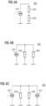
- Figure 4 illustrates a plurality of options in which the first and second pair of coils are connected.
- the first and the second pairs of coils (420, 430) are connected in series to each other and to a current source 410 associated with the transmitter. Accordingly, the same driving current is provided to the first and second pairs of coils.
- the first and second pairs of coils (420, 430) are connected in parallel to each other, as shown in section B of the figure 4 , while being connected to the same current source 410 associated with the transmitter. Accordingly, the driving current is divided between the first pair of coils 420 and the second pair of coils 430.
- the first and the second pair of coils may be connected to two different current sources (410, 415) associated with the transmitter as shown in section c of the figure 4 .
- the first pair of coils 420 are connected to the current source 410 and the second pair of the coils 430 are connected to the current source 415.
- the driving current used to excite the first pair of coils 410 may be different from the driving current used to excite the second pairs of coils 430.
- the frequency or magnitude of the driving current for exciting the first pair of coils 410 may be different from the frequency or magnitude of the driving current for exciting the second pairs of coils 430.
- the first magnetic field may be different from the second magnetic field.
- the coils 345 and 347 and coils 325 and 327 may be excited to generate a third and fourth magnetic fields (350 and 330).
- the driving current provided to the coils 345 and 347, and coils 325 and 327 may be similar or different from the currents provided to the first and second pair of coils (315 & 317, 335 & 337).
- the additional pairs of coils are excited to interact with the first and the second magnetic fields.
- the coils 325 and 327 generate the magnetic field 330 which is capable of interacting with the magnetic field 320 (generated by the coils 315 and 317).
- the magnetic field 330 can tune the magnetic field 320 or amplify the magnetic field 320.
- the coils 345 and 347 generate the magnetic field 350 which is capable of interacting with the magnetic field 340 (generated by the coils 335 and 337).
- the magnetic field 350 can tune the magnetic field 340 or amplify the magnetic field 340.
- the current invention discloses a method 500 for measuring a volumetric flow fluid carrying channel for measuring a volumetric flow of a fluid flowing within the fluid carrying channel using an electromagnetic flowmeter as described above. This is explained using the example method 500 as shown in figure 5 .
- the method 500 is performed by the electromagnetic flowmeter.
- the transmitter of the electromagnetic flowmeter provides a first driving current to a first pair of coils for generating a first magnetic field.
- the transmitter of the electromagnetic flowmeter provides a second driving current to a second pair of coils for generating a second magnetic field.
- the transmitter measures a voltage generated across one or more measuring electrodes due to the interaction of the generated magnetic fields and the conducting fluid.
- the electromagnetic flowmeter determines the volumetric flow of the fluid.
- a magnetic circuit associated with the first magnetic field is distinct is from a magnetic circuit associated with the second magnetic field.
Landscapes
- Physics & Mathematics (AREA)
- Electromagnetism (AREA)
- Fluid Mechanics (AREA)
- General Physics & Mathematics (AREA)
- Engineering & Computer Science (AREA)
- Power Engineering (AREA)
- Measuring Volume Flow (AREA)
Claims (11)
- Elektromagnetischer Durchflussmesser (100), der an einem fluidführenden Kanal zum Messen des Volumenstroms eines in dem fluidführenden Kanal strömenden Fluids installiert werden kann, wobei der elektromagnetische Durchflussmesser (100) Folgendes umfasst:a. einen Messabschnitt (310), der zum Leiten des Fluids durch den elektromagnetischen Durchflussmesser konfiguriert ist;b. mehrere Spulenpaare (315 und 317, 335 und 337, 325 und 327, 345 und 347), die auf dem Umfang des Messabschnitts (310) installiert sind, wobei die mehreren Spulenpaare (315 und 317, 335 und 337, 325 und 327, 345 und 347) Folgendes umfassen:i. ein erstes Spulenpaar (315 und 317), das in der Lage ist, ein erstes Magnetfeld (320) innerhalb des Messabschnitts (310) zu erzeugen, undii. ein zweites Spulenpaar (335 und 337), das in der Lage ist, ein zweites Magnetfeld (340) innerhalb des Messabschnitts (310) zu erzeugen, undc. einen Sender (140) zum Erregen der mehreren Spulenpaare (315 und 317, 335 und 337, 325 und 327, 345 und 347) durch Bereitstellen eines oder mehrerer Ansteuerströme;wobei das erste und das zweite Spulenpaar (315 und 317, 335 und 337) von den mehreren Spulenpaaren (315 und 317, 335 und 337, 325 und 327, 345 und 347) entlang einer ersten Ebene (290) des Messabschnitts (210) installiert sind, wobei die erste Ebene (290) senkrecht zu dem Fluss des Fluids in dem Messabschnitt (310) verläuft, dadurch gekennzeichnet, dassdie mehreren Spulenpaare (315 und 317, 335 und 337, 325 und 327, 345 und 347) ein drittes Spulenpaar (325 und 327) beinhalten, das in der Lage ist, ein drittes Magnetfeld (330) zu erzeugen, wobei das dritte Spulenpaar (325 und 327) bei Detektion eines abnormalen Betriebs erregt wird und wobei das dritte Magnetfeld (330) zum Abstimmen des ersten Magnetfelds (320) und/oder des zweiten Magnetfelds (340) dient.
- Elektromagnetischer Durchflussmesser (100) nach Anspruch 1, wobei der Sender einen ersten Ansteuerstrom für das erste Spulenpaar (315 und 317) zum Erzeugen des ersten Magnetfelds (320) und einen zweiten Ansteuerstrom für das zweite Spulenpaar (335 und 337) zum Erzeugen des zweiten Magnetfelds (340) bereitstellt.
- Elektromagnetischer Durchflussmesser (100) nach Anspruch 1, wobei ein Durchmesser des Messabschnitts innerhalb eines Bereichs von 1200 Millimetern bis 3200 Millimetern liegt.
- Elektromagnetischer Durchflussmesser (100) nach Anspruch 1, wobei die Magnetfeldstärke in der Mitte des Messabschnitts (310) basierend auf dem ersten und dem zweiten Magnetfeld (320 und 340) zwischen 0,01 Millitesla und 10 Millitesla liegt.
- Elektromagnetischer Durchflussmesser (100) nach Anspruch 1, wobei sich das erste Magnetfeld (320) von dem zweiten Magnetfeld (340) unterscheidet und wobei sich ein Wert mindestens eines Parameters, der mit dem ersten Ansteuerstrom assoziiert ist, von einem entsprechenden Wert des entsprechenden mindestens einen Parameters, der mit dem zweiten Ansteuerstrom assoziiert ist, unterscheidet.
- Elektromagnetischer Durchflussmesser (100) nach Anspruch 1, wobei eine erste Spule (315) von dem ersten Spulenpaar (315 und 317) als ein Pol des ersten Magnetfelds (320) wirkt und eine zweite Spule (317) von dem ersten Spulenpaar (315 und 317) als ein anderer Pol des ersten Magnetfelds (320) wirkt.
- Elektromagnetischer Durchflussmesser (100) nach Anspruch 1, wobei sich ein mit dem ersten Magnetfeld (320) assoziierter Magnetkreis von einem mit dem zweiten Magnetfeld (340) assoziierten Magnetkreis unterscheidet.
- Elektromagnetischer Durchflussmesser (100) nach Anspruch 1, wobei das erste Spulenpaar (315 und 317) und das zweite Spulenpaar (335 und 337) in einer Reihenschaltung miteinander verbunden sind.
- Elektromagnetischer Durchflussmesser nach Anspruch 1, wobei das erste Spulenpaar (315 und 317) und das zweite Spulenpaar (335 und 337) in einer Parallelschaltung miteinander verbunden sind.
- Elektromagnetischer Durchflussmesser nach Anspruch 1, wobei das erste Spulenpaar (315 und 317) über eine erste elektrische Verbindung mit dem Sender verbunden ist und wobei das zweite Spulenpaar (335 und 337) über eine zweite elektrische Verbindung mit dem Sender verbunden ist.
- Verfahren (500) zur Messung eines Volumenstromfluid führenden Kanals zum Messen eines Volumenstroms eines innerhalb des fluidführenden Kanals fließenden Fluids unter Verwendung eines elektromagnetischen Durchflussmessers (100), wobei der elektromagnetische Durchflussmesser (100) einen Messabschnitt (310), der zum Leiten des Fluids durch den elektromagnetischen Durchflussmesser konfiguriert ist, mehrere Spulenpaare (315 und 317, 335 und 337, 325 und 327, 345 und 347), die auf dem Umfang des Messabschnitts (310) installiert sind, und einen Sender (140) zum Erregen der mehreren Spulenpaare (315 und 317, 335 und 337, 325 und 327, 345 und 347) durch Bereitstellen eines oder mehrerer Ansteuerströme umfasst, wobei das Verfahren (500) Folgendes umfasst:a. Bereitstellen (510) eines ersten Ansteuerstroms für ein erstes Spulenpaar (315 und 317) zum Erzeugen eines ersten Magnetfelds (320); undb. Bereitstellen (520) eines zweiten Ansteuerstroms für ein zweites Spulenpaar (335 und 337) zum Erzeugen eines zweiten Magnetfelds (340);c. Messen (530) einer Spannung an zwei oder mehr Messelektroden zum Bestimmen eines Fluidvolumenstroms;wobei sich ein mit dem ersten Magnetfeld (320) assoziierter Magnetkreis von einem mit dem zweiten Magnetfeld (340) assoziierten Magnetkreis unterscheidet, dadurch gekennzeichnet, dass das Verfahren (500) ferner Folgendes umfasst:d. Bestimmen eines Parameters, der mit dem ersten Magnetfeld assoziiert ist (320), unde. Bereitstellen eines dritten Ansteuerstroms für ein drittes Spulenpaar (325 und 327) basierend auf dem mit dem ersten Magnetfeld (320) assoziierten Parameter,wobei das dritte Spulenpaar (325 und 327) ein drittes Magnetfeld (330) zum Abstimmen des ersten Magnetfelds (320) erzeugt.
Applications Claiming Priority (2)
| Application Number | Priority Date | Filing Date | Title |
|---|---|---|---|
| EP21166163.2A EP4067832A1 (de) | 2021-03-31 | 2021-03-31 | Elektromagnetischer durchflussmesser mit mehreren spulen |
| PCT/EP2022/057911 WO2022207487A1 (en) | 2021-03-31 | 2022-03-25 | An electromagnetic flowmeter with a plurality of coils |
Publications (2)
| Publication Number | Publication Date |
|---|---|
| EP4271968A1 EP4271968A1 (de) | 2023-11-08 |
| EP4271968B1 true EP4271968B1 (de) | 2025-06-11 |
Family
ID=75339458
Family Applications (2)
| Application Number | Title | Priority Date | Filing Date |
|---|---|---|---|
| EP21166163.2A Withdrawn EP4067832A1 (de) | 2021-03-31 | 2021-03-31 | Elektromagnetischer durchflussmesser mit mehreren spulen |
| EP22717815.9A Active EP4271968B1 (de) | 2021-03-31 | 2022-03-25 | Elektromagnetischer durchflussmesser mit mehreren spulen |
Family Applications Before (1)
| Application Number | Title | Priority Date | Filing Date |
|---|---|---|---|
| EP21166163.2A Withdrawn EP4067832A1 (de) | 2021-03-31 | 2021-03-31 | Elektromagnetischer durchflussmesser mit mehreren spulen |
Country Status (4)
| Country | Link |
|---|---|
| US (1) | US12540840B2 (de) |
| EP (2) | EP4067832A1 (de) |
| CN (1) | CN117098973A (de) |
| WO (1) | WO2022207487A1 (de) |
Families Citing this family (1)
| Publication number | Priority date | Publication date | Assignee | Title |
|---|---|---|---|---|
| GB2588201B (en) * | 2019-10-15 | 2024-08-14 | Flodatix Ltd | Apparatus for monitoring fluid flow in a pipe using electromagnetic velocity tomography |
Family Cites Families (9)
| Publication number | Priority date | Publication date | Assignee | Title |
|---|---|---|---|---|
| US3490282A (en) * | 1966-07-28 | 1970-01-20 | Tokyo Shibaura Electric Co | Induction liquid flowmeters |
| DE1911556A1 (de) * | 1969-03-07 | 1970-09-24 | Krohne Fa Ludwig | Induktiver Stroemungsmesser |
| JPS62188910A (ja) * | 1986-02-14 | 1987-08-18 | Aichi Tokei Denki Co Ltd | 電磁流量計 |
| US5263374A (en) * | 1992-01-24 | 1993-11-23 | Marsh-Mcbirney, Inc. | Flowmeter with concentrically arranged electromagnetic field |
| US5866823A (en) * | 1997-05-13 | 1999-02-02 | Hersey Measurement Company | Commutating electrode magnetic flowmeter |
| US10031009B2 (en) * | 2011-08-23 | 2018-07-24 | Cidra Corporate Services, Inc. | Flow profiling techniques based on modulated magnetic-electrical impedance tomography |
| CA2882286C (en) * | 2012-08-14 | 2018-09-18 | Cidra Corporate Services Inc. | Flow profiling techniques based on modulated magnetic-electrical impedance tomography |
| EP3184969A1 (de) * | 2015-12-21 | 2017-06-28 | Proces-Data A/S | Elektromagnetischer durchflussmesser mit mehreren elektroden |
| US11204267B2 (en) * | 2019-09-05 | 2021-12-21 | Micro Motion, Inc. | Continuously adaptive digital coil driver for magnetic flowmeter |
-
2021
- 2021-03-31 EP EP21166163.2A patent/EP4067832A1/de not_active Withdrawn
-
2022
- 2022-03-25 CN CN202280025902.3A patent/CN117098973A/zh active Pending
- 2022-03-25 US US18/284,562 patent/US12540840B2/en active Active
- 2022-03-25 EP EP22717815.9A patent/EP4271968B1/de active Active
- 2022-03-25 WO PCT/EP2022/057911 patent/WO2022207487A1/en not_active Ceased
Also Published As
| Publication number | Publication date |
|---|---|
| EP4271968A1 (de) | 2023-11-08 |
| CN117098973A (zh) | 2023-11-21 |
| EP4067832A1 (de) | 2022-10-05 |
| US12540840B2 (en) | 2026-02-03 |
| WO2022207487A1 (en) | 2022-10-06 |
| US20240175732A1 (en) | 2024-05-30 |
Similar Documents
| Publication | Publication Date | Title |
|---|---|---|
| RU2615205C2 (ru) | Магнитный расходомер с множественными катушками | |
| JP5818415B2 (ja) | 電磁流量計測システムの校正装置 | |
| JP2009258125A (ja) | 流体用の磁気誘導式流量測定計および磁気誘導式流量測定方法 | |
| JP6272500B2 (ja) | 磁気流量計のための改善された磁性コア構成 | |
| EP3022532B1 (de) | Magnetischer flussmesser | |
| WO2016079999A1 (ja) | 電磁流量計 | |
| CN103575342A (zh) | 电磁感应的流量测量仪 | |
| EP4271968B1 (de) | Elektromagnetischer durchflussmesser mit mehreren spulen | |
| WO2012132363A1 (ja) | 電磁流量計、電磁流量計測システム及び方法 | |
| US10670435B2 (en) | Magnetic-inductive flowmeter and corresponding method | |
| US7267012B2 (en) | Electromagnetic flowmeter including electrodes and magnetic pole placed in proximity on one side of the outer wall | |
| CN114341596A (zh) | 磁感应流量计 | |
| EP4275018B1 (de) | Elektromagnetischer durchflussmesser mit primären und sekundären spulenpaaren | |
| EP3628982B1 (de) | Magnetflussmesseranordnung mit vollständiger bohrung | |
| JP2001281028A (ja) | 電磁流量計 | |
| RU2310816C2 (ru) | Вихревой электромагнитный преобразователь расхода жидкого металла | |
| CN111771104B (zh) | 电磁流量计 | |
| RU2239789C1 (ru) | Способ измерения расхода жидкости и электромагнитный преобразователь для измерения расхода жидкости | |
| WO2018229523A1 (en) | An electromagnetic flowmeter assembly | |
| JPH0695029B2 (ja) | 電磁流量計 |
Legal Events
| Date | Code | Title | Description |
|---|---|---|---|
| STAA | Information on the status of an ep patent application or granted ep patent |
Free format text: STATUS: UNKNOWN |
|
| STAA | Information on the status of an ep patent application or granted ep patent |
Free format text: STATUS: THE INTERNATIONAL PUBLICATION HAS BEEN MADE |
|
| PUAI | Public reference made under article 153(3) epc to a published international application that has entered the european phase |
Free format text: ORIGINAL CODE: 0009012 |
|
| STAA | Information on the status of an ep patent application or granted ep patent |
Free format text: STATUS: REQUEST FOR EXAMINATION WAS MADE |
|
| 17P | Request for examination filed |
Effective date: 20230804 |
|
| AK | Designated contracting states |
Kind code of ref document: A1 Designated state(s): AL AT BE BG CH CY CZ DE DK EE ES FI FR GB GR HR HU IE IS IT LI LT LU LV MC MK MT NL NO PL PT RO RS SE SI SK SM TR |
|
| DAV | Request for validation of the european patent (deleted) | ||
| DAX | Request for extension of the european patent (deleted) | ||
| GRAP | Despatch of communication of intention to grant a patent |
Free format text: ORIGINAL CODE: EPIDOSNIGR1 |
|
| STAA | Information on the status of an ep patent application or granted ep patent |
Free format text: STATUS: GRANT OF PATENT IS INTENDED |
|
| INTG | Intention to grant announced |
Effective date: 20250219 |
|
| GRAS | Grant fee paid |
Free format text: ORIGINAL CODE: EPIDOSNIGR3 |
|
| GRAA | (expected) grant |
Free format text: ORIGINAL CODE: 0009210 |
|
| STAA | Information on the status of an ep patent application or granted ep patent |
Free format text: STATUS: THE PATENT HAS BEEN GRANTED |
|
| AK | Designated contracting states |
Kind code of ref document: B1 Designated state(s): AL AT BE BG CH CY CZ DE DK EE ES FI FR GB GR HR HU IE IS IT LI LT LU LV MC MK MT NL NO PL PT RO RS SE SI SK SM TR |
|
| REG | Reference to a national code |
Ref country code: GB Ref legal event code: FG4D |
|
| REG | Reference to a national code |
Ref country code: CH Ref legal event code: EP |
|
| REG | Reference to a national code |
Ref country code: IE Ref legal event code: FG4D |
|
| REG | Reference to a national code |
Ref country code: DE Ref legal event code: R096 Ref document number: 602022015817 Country of ref document: DE |
|
| PG25 | Lapsed in a contracting state [announced via postgrant information from national office to epo] |
Ref country code: FI Free format text: LAPSE BECAUSE OF FAILURE TO SUBMIT A TRANSLATION OF THE DESCRIPTION OR TO PAY THE FEE WITHIN THE PRESCRIBED TIME-LIMIT Effective date: 20250611 Ref country code: ES Free format text: LAPSE BECAUSE OF FAILURE TO SUBMIT A TRANSLATION OF THE DESCRIPTION OR TO PAY THE FEE WITHIN THE PRESCRIBED TIME-LIMIT Effective date: 20250611 |
|
| REG | Reference to a national code |
Ref country code: LT Ref legal event code: MG9D |
|
| PG25 | Lapsed in a contracting state [announced via postgrant information from national office to epo] |
Ref country code: GR Free format text: LAPSE BECAUSE OF FAILURE TO SUBMIT A TRANSLATION OF THE DESCRIPTION OR TO PAY THE FEE WITHIN THE PRESCRIBED TIME-LIMIT Effective date: 20250912 Ref country code: NO Free format text: LAPSE BECAUSE OF FAILURE TO SUBMIT A TRANSLATION OF THE DESCRIPTION OR TO PAY THE FEE WITHIN THE PRESCRIBED TIME-LIMIT Effective date: 20250911 |
|
| REG | Reference to a national code |
Ref country code: NL Ref legal event code: MP Effective date: 20250611 |
|
| PG25 | Lapsed in a contracting state [announced via postgrant information from national office to epo] |
Ref country code: BG Free format text: LAPSE BECAUSE OF FAILURE TO SUBMIT A TRANSLATION OF THE DESCRIPTION OR TO PAY THE FEE WITHIN THE PRESCRIBED TIME-LIMIT Effective date: 20250611 |
|
| PG25 | Lapsed in a contracting state [announced via postgrant information from national office to epo] |
Ref country code: HR Free format text: LAPSE BECAUSE OF FAILURE TO SUBMIT A TRANSLATION OF THE DESCRIPTION OR TO PAY THE FEE WITHIN THE PRESCRIBED TIME-LIMIT Effective date: 20250611 |
|
| PG25 | Lapsed in a contracting state [announced via postgrant information from national office to epo] |
Ref country code: RS Free format text: LAPSE BECAUSE OF FAILURE TO SUBMIT A TRANSLATION OF THE DESCRIPTION OR TO PAY THE FEE WITHIN THE PRESCRIBED TIME-LIMIT Effective date: 20250911 |
|
| PG25 | Lapsed in a contracting state [announced via postgrant information from national office to epo] |
Ref country code: LV Free format text: LAPSE BECAUSE OF FAILURE TO SUBMIT A TRANSLATION OF THE DESCRIPTION OR TO PAY THE FEE WITHIN THE PRESCRIBED TIME-LIMIT Effective date: 20250611 |
|
| PG25 | Lapsed in a contracting state [announced via postgrant information from national office to epo] |
Ref country code: NL Free format text: LAPSE BECAUSE OF FAILURE TO SUBMIT A TRANSLATION OF THE DESCRIPTION OR TO PAY THE FEE WITHIN THE PRESCRIBED TIME-LIMIT Effective date: 20250611 |
|
| PG25 | Lapsed in a contracting state [announced via postgrant information from national office to epo] |
Ref country code: PT Free format text: LAPSE BECAUSE OF FAILURE TO SUBMIT A TRANSLATION OF THE DESCRIPTION OR TO PAY THE FEE WITHIN THE PRESCRIBED TIME-LIMIT Effective date: 20251013 |
|
| REG | Reference to a national code |
Ref country code: AT Ref legal event code: MK05 Ref document number: 1802589 Country of ref document: AT Kind code of ref document: T Effective date: 20250611 |
|
| PG25 | Lapsed in a contracting state [announced via postgrant information from national office to epo] |
Ref country code: IS Free format text: LAPSE BECAUSE OF FAILURE TO SUBMIT A TRANSLATION OF THE DESCRIPTION OR TO PAY THE FEE WITHIN THE PRESCRIBED TIME-LIMIT Effective date: 20251011 |
|
| PG25 | Lapsed in a contracting state [announced via postgrant information from national office to epo] |
Ref country code: AT Free format text: LAPSE BECAUSE OF FAILURE TO SUBMIT A TRANSLATION OF THE DESCRIPTION OR TO PAY THE FEE WITHIN THE PRESCRIBED TIME-LIMIT Effective date: 20250611 Ref country code: SM Free format text: LAPSE BECAUSE OF FAILURE TO SUBMIT A TRANSLATION OF THE DESCRIPTION OR TO PAY THE FEE WITHIN THE PRESCRIBED TIME-LIMIT Effective date: 20250611 |
|
| PG25 | Lapsed in a contracting state [announced via postgrant information from national office to epo] |
Ref country code: CZ Free format text: LAPSE BECAUSE OF FAILURE TO SUBMIT A TRANSLATION OF THE DESCRIPTION OR TO PAY THE FEE WITHIN THE PRESCRIBED TIME-LIMIT Effective date: 20250611 |
|
| PG25 | Lapsed in a contracting state [announced via postgrant information from national office to epo] |
Ref country code: PL Free format text: LAPSE BECAUSE OF FAILURE TO SUBMIT A TRANSLATION OF THE DESCRIPTION OR TO PAY THE FEE WITHIN THE PRESCRIBED TIME-LIMIT Effective date: 20250611 |
|
| PG25 | Lapsed in a contracting state [announced via postgrant information from national office to epo] |
Ref country code: EE Free format text: LAPSE BECAUSE OF FAILURE TO SUBMIT A TRANSLATION OF THE DESCRIPTION OR TO PAY THE FEE WITHIN THE PRESCRIBED TIME-LIMIT Effective date: 20250611 |
|
| PG25 | Lapsed in a contracting state [announced via postgrant information from national office to epo] |
Ref country code: SK Free format text: LAPSE BECAUSE OF FAILURE TO SUBMIT A TRANSLATION OF THE DESCRIPTION OR TO PAY THE FEE WITHIN THE PRESCRIBED TIME-LIMIT Effective date: 20250611 |