EP4270957A2 - Picture coding supporting block merging and skip mode - Google Patents
Picture coding supporting block merging and skip mode Download PDFInfo
- Publication number
- EP4270957A2 EP4270957A2 EP23179369.6A EP23179369A EP4270957A2 EP 4270957 A2 EP4270957 A2 EP 4270957A2 EP 23179369 A EP23179369 A EP 23179369A EP 4270957 A2 EP4270957 A2 EP 4270957A2
- Authority
- EP
- European Patent Office
- Prior art keywords
- picture
- bitstream
- block
- coding parameters
- blocks
- Prior art date
- Legal status (The legal status is an assumption and is not a legal conclusion. Google has not performed a legal analysis and makes no representation as to the accuracy of the status listed.)
- Pending
Links
- 230000004913 activation Effects 0.000 claims abstract description 33
- 238000007670 refining Methods 0.000 claims abstract description 14
- 238000000638 solvent extraction Methods 0.000 claims description 184
- 238000005192 partition Methods 0.000 claims description 159
- 238000000034 method Methods 0.000 claims description 56
- 239000000284 extract Substances 0.000 claims description 21
- 238000000605 extraction Methods 0.000 claims description 19
- 238000003491 array Methods 0.000 claims description 18
- 230000003213 activating effect Effects 0.000 claims description 5
- 239000000523 sample Substances 0.000 description 316
- 230000033001 locomotion Effects 0.000 description 62
- 230000011664 signaling Effects 0.000 description 51
- 230000000875 corresponding effect Effects 0.000 description 31
- 239000013598 vector Substances 0.000 description 26
- 241000023320 Luma <angiosperm> Species 0.000 description 22
- OSWPMRLSEDHDFF-UHFFFAOYSA-N methyl salicylate Chemical compound COC(=O)C1=CC=CC=C1O OSWPMRLSEDHDFF-UHFFFAOYSA-N 0.000 description 22
- 230000008569 process Effects 0.000 description 13
- 230000005540 biological transmission Effects 0.000 description 12
- 230000002123 temporal effect Effects 0.000 description 12
- 238000004590 computer program Methods 0.000 description 11
- 230000006870 function Effects 0.000 description 11
- 238000010586 diagram Methods 0.000 description 6
- 230000009849 deactivation Effects 0.000 description 5
- 238000005457 optimization Methods 0.000 description 5
- 238000013459 approach Methods 0.000 description 4
- PXFBZOLANLWPMH-UHFFFAOYSA-N 16-Epiaffinine Natural products C1C(C2=CC=CC=C2N2)=C2C(=O)CC2C(=CC)CN(C)C1C2CO PXFBZOLANLWPMH-UHFFFAOYSA-N 0.000 description 3
- 230000003044 adaptive effect Effects 0.000 description 3
- 238000009795 derivation Methods 0.000 description 3
- 238000006073 displacement reaction Methods 0.000 description 3
- 238000003780 insertion Methods 0.000 description 3
- 230000037431 insertion Effects 0.000 description 3
- 238000013139 quantization Methods 0.000 description 3
- 230000009467 reduction Effects 0.000 description 3
- 230000009466 transformation Effects 0.000 description 3
- 230000008901 benefit Effects 0.000 description 2
- 230000001419 dependent effect Effects 0.000 description 2
- 230000002349 favourable effect Effects 0.000 description 2
- 230000004048 modification Effects 0.000 description 2
- 238000012986 modification Methods 0.000 description 2
- 238000012545 processing Methods 0.000 description 2
- 208000037170 Delayed Emergence from Anesthesia Diseases 0.000 description 1
- 241001025261 Neoraja caerulea Species 0.000 description 1
- 230000006978 adaptation Effects 0.000 description 1
- 230000006399 behavior Effects 0.000 description 1
- 230000008859 change Effects 0.000 description 1
- 238000004891 communication Methods 0.000 description 1
- 239000012141 concentrate Substances 0.000 description 1
- 230000003750 conditioning effect Effects 0.000 description 1
- 230000002596 correlated effect Effects 0.000 description 1
- 238000013075 data extraction Methods 0.000 description 1
- 230000003247 decreasing effect Effects 0.000 description 1
- 230000000694 effects Effects 0.000 description 1
- 238000005286 illumination Methods 0.000 description 1
- 239000013074 reference sample Substances 0.000 description 1
- 238000004088 simulation Methods 0.000 description 1
- GOLXNESZZPUPJE-UHFFFAOYSA-N spiromesifen Chemical compound CC1=CC(C)=CC(C)=C1C(C(O1)=O)=C(OC(=O)CC(C)(C)C)C11CCCC1 GOLXNESZZPUPJE-UHFFFAOYSA-N 0.000 description 1
- 238000012360 testing method Methods 0.000 description 1
- 238000012546 transfer Methods 0.000 description 1
Images


Classifications
-
- H—ELECTRICITY
- H04—ELECTRIC COMMUNICATION TECHNIQUE
- H04N—PICTORIAL COMMUNICATION, e.g. TELEVISION
- H04N19/00—Methods or arrangements for coding, decoding, compressing or decompressing digital video signals
- H04N19/50—Methods or arrangements for coding, decoding, compressing or decompressing digital video signals using predictive coding
- H04N19/503—Methods or arrangements for coding, decoding, compressing or decompressing digital video signals using predictive coding involving temporal prediction
- H04N19/51—Motion estimation or motion compensation
- H04N19/513—Processing of motion vectors
- H04N19/517—Processing of motion vectors by encoding
- H04N19/52—Processing of motion vectors by encoding by predictive encoding
-
- H—ELECTRICITY
- H04—ELECTRIC COMMUNICATION TECHNIQUE
- H04N—PICTORIAL COMMUNICATION, e.g. TELEVISION
- H04N19/00—Methods or arrangements for coding, decoding, compressing or decompressing digital video signals
- H04N19/10—Methods or arrangements for coding, decoding, compressing or decompressing digital video signals using adaptive coding
- H04N19/134—Methods or arrangements for coding, decoding, compressing or decompressing digital video signals using adaptive coding characterised by the element, parameter or criterion affecting or controlling the adaptive coding
- H04N19/157—Assigned coding mode, i.e. the coding mode being predefined or preselected to be further used for selection of another element or parameter
-
- H—ELECTRICITY
- H04—ELECTRIC COMMUNICATION TECHNIQUE
- H04N—PICTORIAL COMMUNICATION, e.g. TELEVISION
- H04N19/00—Methods or arrangements for coding, decoding, compressing or decompressing digital video signals
- H04N19/70—Methods or arrangements for coding, decoding, compressing or decompressing digital video signals characterised by syntax aspects related to video coding, e.g. related to compression standards
-
- H—ELECTRICITY
- H04—ELECTRIC COMMUNICATION TECHNIQUE
- H04N—PICTORIAL COMMUNICATION, e.g. TELEVISION
- H04N19/00—Methods or arrangements for coding, decoding, compressing or decompressing digital video signals
- H04N19/10—Methods or arrangements for coding, decoding, compressing or decompressing digital video signals using adaptive coding
- H04N19/102—Methods or arrangements for coding, decoding, compressing or decompressing digital video signals using adaptive coding characterised by the element, parameter or selection affected or controlled by the adaptive coding
- H04N19/103—Selection of coding mode or of prediction mode
-
- H—ELECTRICITY
- H04—ELECTRIC COMMUNICATION TECHNIQUE
- H04N—PICTORIAL COMMUNICATION, e.g. TELEVISION
- H04N19/00—Methods or arrangements for coding, decoding, compressing or decompressing digital video signals
- H04N19/10—Methods or arrangements for coding, decoding, compressing or decompressing digital video signals using adaptive coding
- H04N19/102—Methods or arrangements for coding, decoding, compressing or decompressing digital video signals using adaptive coding characterised by the element, parameter or selection affected or controlled by the adaptive coding
- H04N19/119—Adaptive subdivision aspects, e.g. subdivision of a picture into rectangular or non-rectangular coding blocks
-
- H—ELECTRICITY
- H04—ELECTRIC COMMUNICATION TECHNIQUE
- H04N—PICTORIAL COMMUNICATION, e.g. TELEVISION
- H04N19/00—Methods or arrangements for coding, decoding, compressing or decompressing digital video signals
- H04N19/10—Methods or arrangements for coding, decoding, compressing or decompressing digital video signals using adaptive coding
- H04N19/102—Methods or arrangements for coding, decoding, compressing or decompressing digital video signals using adaptive coding characterised by the element, parameter or selection affected or controlled by the adaptive coding
- H04N19/13—Adaptive entropy coding, e.g. adaptive variable length coding [AVLC] or context adaptive binary arithmetic coding [CABAC]
-
- H—ELECTRICITY
- H04—ELECTRIC COMMUNICATION TECHNIQUE
- H04N—PICTORIAL COMMUNICATION, e.g. TELEVISION
- H04N19/00—Methods or arrangements for coding, decoding, compressing or decompressing digital video signals
- H04N19/10—Methods or arrangements for coding, decoding, compressing or decompressing digital video signals using adaptive coding
- H04N19/134—Methods or arrangements for coding, decoding, compressing or decompressing digital video signals using adaptive coding characterised by the element, parameter or criterion affecting or controlling the adaptive coding
- H04N19/157—Assigned coding mode, i.e. the coding mode being predefined or preselected to be further used for selection of another element or parameter
- H04N19/159—Prediction type, e.g. intra-frame, inter-frame or bidirectional frame prediction
-
- H—ELECTRICITY
- H04—ELECTRIC COMMUNICATION TECHNIQUE
- H04N—PICTORIAL COMMUNICATION, e.g. TELEVISION
- H04N19/00—Methods or arrangements for coding, decoding, compressing or decompressing digital video signals
- H04N19/10—Methods or arrangements for coding, decoding, compressing or decompressing digital video signals using adaptive coding
- H04N19/169—Methods or arrangements for coding, decoding, compressing or decompressing digital video signals using adaptive coding characterised by the coding unit, i.e. the structural portion or semantic portion of the video signal being the object or the subject of the adaptive coding
- H04N19/17—Methods or arrangements for coding, decoding, compressing or decompressing digital video signals using adaptive coding characterised by the coding unit, i.e. the structural portion or semantic portion of the video signal being the object or the subject of the adaptive coding the unit being an image region, e.g. an object
- H04N19/172—Methods or arrangements for coding, decoding, compressing or decompressing digital video signals using adaptive coding characterised by the coding unit, i.e. the structural portion or semantic portion of the video signal being the object or the subject of the adaptive coding the unit being an image region, e.g. an object the region being a picture, frame or field
-
- H—ELECTRICITY
- H04—ELECTRIC COMMUNICATION TECHNIQUE
- H04N—PICTORIAL COMMUNICATION, e.g. TELEVISION
- H04N19/00—Methods or arrangements for coding, decoding, compressing or decompressing digital video signals
- H04N19/10—Methods or arrangements for coding, decoding, compressing or decompressing digital video signals using adaptive coding
- H04N19/169—Methods or arrangements for coding, decoding, compressing or decompressing digital video signals using adaptive coding characterised by the coding unit, i.e. the structural portion or semantic portion of the video signal being the object or the subject of the adaptive coding
- H04N19/17—Methods or arrangements for coding, decoding, compressing or decompressing digital video signals using adaptive coding characterised by the coding unit, i.e. the structural portion or semantic portion of the video signal being the object or the subject of the adaptive coding the unit being an image region, e.g. an object
- H04N19/176—Methods or arrangements for coding, decoding, compressing or decompressing digital video signals using adaptive coding characterised by the coding unit, i.e. the structural portion or semantic portion of the video signal being the object or the subject of the adaptive coding the unit being an image region, e.g. an object the region being a block, e.g. a macroblock
-
- H—ELECTRICITY
- H04—ELECTRIC COMMUNICATION TECHNIQUE
- H04N—PICTORIAL COMMUNICATION, e.g. TELEVISION
- H04N19/00—Methods or arrangements for coding, decoding, compressing or decompressing digital video signals
- H04N19/10—Methods or arrangements for coding, decoding, compressing or decompressing digital video signals using adaptive coding
- H04N19/169—Methods or arrangements for coding, decoding, compressing or decompressing digital video signals using adaptive coding characterised by the coding unit, i.e. the structural portion or semantic portion of the video signal being the object or the subject of the adaptive coding
- H04N19/184—Methods or arrangements for coding, decoding, compressing or decompressing digital video signals using adaptive coding characterised by the coding unit, i.e. the structural portion or semantic portion of the video signal being the object or the subject of the adaptive coding the unit being bits, e.g. of the compressed video stream
-
- H—ELECTRICITY
- H04—ELECTRIC COMMUNICATION TECHNIQUE
- H04N—PICTORIAL COMMUNICATION, e.g. TELEVISION
- H04N19/00—Methods or arrangements for coding, decoding, compressing or decompressing digital video signals
- H04N19/10—Methods or arrangements for coding, decoding, compressing or decompressing digital video signals using adaptive coding
- H04N19/169—Methods or arrangements for coding, decoding, compressing or decompressing digital video signals using adaptive coding characterised by the coding unit, i.e. the structural portion or semantic portion of the video signal being the object or the subject of the adaptive coding
- H04N19/186—Methods or arrangements for coding, decoding, compressing or decompressing digital video signals using adaptive coding characterised by the coding unit, i.e. the structural portion or semantic portion of the video signal being the object or the subject of the adaptive coding the unit being a colour or a chrominance component
-
- H—ELECTRICITY
- H04—ELECTRIC COMMUNICATION TECHNIQUE
- H04N—PICTORIAL COMMUNICATION, e.g. TELEVISION
- H04N19/00—Methods or arrangements for coding, decoding, compressing or decompressing digital video signals
- H04N19/50—Methods or arrangements for coding, decoding, compressing or decompressing digital video signals using predictive coding
Definitions
- the present application concerns picture and/or video coding and in particular codecs supporting block partitioning and skip mode.
- multi-tree partitioning subdivision seeks to increase the freedom of subdividing a picture into blocks at a reasonable demand for subdivision information. Nevertheless, even multi-tree subdivision necessitates the signalization of a remarkable amount of data and the freedom in subdividing a picture is quite restricted even in case of using such multi-tree subdivisioning.
- merging of blocks may be used in order to increase the number of possible picture subdivisionings at a reasonable amount of additional data necessary in order to signalize the merging information.
- the coding parameters need to be transmitted within the bitstream in full merely once, similarly as if the resulting merged group of blocks was a directly subdivided portion of the picture.
- skip mode In order to additionally increase the efficiency in encoding the picture content, skip mode has been introduced into some block-based picture codecs, the skip mode enabling the encoder to refrain from transmitting the residual data of a certain block to the decoder. That is, the skip mode is a possibility to suppress residual data transmission for certain blocks.
- the ability to suppress the transmission of residual data for certain blocks results in a broader granularity interval for encoding the coding/prediction parameters within which an optimum tradeoff between coding quality on the one hand and total bit rate spent on the other hand may be expected: naturally, increasing the spatial resolution of the encoding of the coding/prediction parameters results in an increase of the side information rate while decreasing, however, the residuum thereby lowering the rate necessary to encode the residual data.
- the object of the present invention is to provide a coding concept having an increased coding efficiency. This object is achieved by the pending independent claims.
- the idea underlying the present invention is that a further coding efficiency increase may be achieved if a common signalization is used within the bitstream with regard to both activation of merging and activation of the skip mode. That is, one of the possible states of one or more syntax elements within the bitstream may signalize for a current sample set of a picture that the respective sample set is to be merged and has no prediction residual encoded and inserted into the bitstream.
- a common flag may commonly signalize whether the coding parameters associated with a current sample set are to be set according to a merge candidate or to be retrieved from the bitstream, and whether the current sample set of the picture is to be reconstructed merely based on a prediction signal depending on the coding parameters associated with the current sample set, without any residual data, or to be reconstructed by refining the prediction signal depending on the coding parameters associated with the current sample set by means of residual data within the bitstream.
- the inventors of the present invention found out that this introduction of a common signalization of the activation of the merging on the one hand and the activation of the skip mode on the other hand saves bit rate as additional overhead in order to signalize the activation of the merging and/or skip mode separately from each other may be reduced or may merely have to be spent in case of the merging and the skip mode not being activated concurrently.
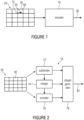
- Fig. 1 shows an apparatus 10 for encoding a picture 20 into a bitstream 30.
- picture 20 could be part of a video, in which case the encoder 10 would be a video encoder.
- the picture 20 is, although not explicitly shown in Fig. 1 , represented as an array of samples.
- the sample array of picture 20 is partitioned into sample sets 40, which could be any set of samples such as sample sets covering non-overlapping single-connected areas of picture 20.
- sample sets 40 are shown as, and are called in the following, blocks 40, wherein however, the following description shall not be regarded as being restricted to any special kind of sample sets 40.
- the sample sets 40 are rectangular and/or quadratic blocks.
- the picture 20 may be subdivided into a regular arrangement of blocks 40 so that the blocks 40 are arranged in rows and columns as exemplarily shown in Fig. 1 .
- any other subdivision of the picture 20 into blocks 40 may also be possible.
- subdivision of the picture 20 into blocks 40 may be fixed, i.e., known to the decoder by default or may be signaled within the bitstream 30 to the decoder.
- blocks 40 of picture 20 may vary in size.
- a multi-tree subdivision such as a quad-tree subdivision may be applied to picture 20 or to a regular pre-subdivisioning of picture 20 into regularly arranged tree-root blocks so as to obtain blocks 40 which, in this case, form the leaf blocks of the multi-tree subdivision of the tree-root blocks.
- the encoder 10 is configured to encode, for current sample set 40, a flag into the bitstream 30 commonly signaling whether the coding parameters associated with the current sample set 40 are to be set according to a merge candidate or to be retrieved from the bitstream 30, and whether the current sample set of the picture 20 is to be reconstructed merely based on a prediction signal depending on the coding parameters associated with the current sample set, without any residual data, or to be reconstructed by refining the prediction signal depending on the coding parameters associated with the current sample set 40 by means of a residual data within the bitstream 30.
- the encoder 10 is configured to encode, for current sample set 40, a flag into the bitstream 30 commonly signaling, if assuming a first state, that the coding parameters associated with the current sample set 40 are to be set according to a merge candidate rather than to be retrieved from the bitstream 30, and that the current sample set of the picture 20 is to be reconstructed merely based on a prediction signal depending on the coding parameters associated with the current sample set, without any residual data, and if assuming any other state that the coding parameters associated with the current sample set 40 are to be retrieved from the bitstream 30, or that the current sample set of the picture 20 is to be reconstructed by refining the prediction signal depending on the coding parameters associated with the current sample set 40 by means of a residual data within the bitstream 30.
- the encoder 10 supports merging of blocks 40.
- the merging is facultative. That is, not every block 40 is subject to merging. For some blocks 40 it is, in some, for example, rate-distortion optimization sense favorable to merge the current block 40 with a merge candidate, but for others the opposite is true.
- the encoder 10 determines a set or list of merge candidates and checks, for each of these merge candidates, whether merging the current block 40 with that merge candidate forms the most preferred coding option in, for example, rate-distortion optimization sense.
- the encoder 10 is configured to determine the set or list of merge candidates for a current block 40 based on previously encoded portions of bitstream 30.
- encoder 10 derives at least a portion of the set or list of merge candidates by adopting the coding parameters associated with locally and/or temporally neighboring blocks 40 which have been previously encoded in accordance with the encoding order applied by encoder 10.
- Temporal neighborhood denotes, for example, blocks of previously encoded pictures of a video to which picture 20 belongs, with the temporally neighboring blocks thereof being spatially located so as to spatially overlap the current block 40 of the current picture 20. Accordingly, for this portion of the set or list of merge candidates, there is a one to one association between each merge candidate and the spatially and/or temporally neighboring blocks.
- Each merge candidate has coding parameters associated therewith.
- encoder 10 sets the coding parameters of the current block 40 in accordance with the merge candidate. For example, encoder 10 may set the coding parameters of the current block 40 to be equal to the respective merge candidate, i.e. encoder 10 may copy the coding parameters of the current block 40 from the respective merge candidate.
- the coding parameters of a merge candidate are directly adopted from a spatially and/or temporally neighboring block, or the coding parameters of the respective merge candidate is obtained from the coding parameters of such a spatially and/or temporally neighboring block by adopting same, i.e.
- motion parameters may, however, refer to different reference picture indices.
- motion parameters to be adopted may refer to a certain time interval between the current picture and the reference picture, and in merging the current block with the respective merge candidate having respective motion parameters, encoder 10 may be configured to scale the motion parameters of the respective merge candidate in order to adapt its time interval to the time interval selected for the current block.
- merging blocks 40 with any of the just-outlined merge candidates may be thought of as a merging of these blocks into groups of one or more blocks 40 so that the coding parameters do not vary across the picture 20 within these groups of blocks 40, except for the scaling adaptions or the like.
- the merging with any of the just-outlined merge candidates reduces the granularity at which the coding parameters vary over the picture 20.
- the merging with any of the just-outlined merge candidates results in an additional freedom in subdividing picture 20 into blocks 40 and groups of blocks 40, respectively.
- the merging of blocks 40 into such groups of blocks may be thought of causing the encoder 10 to encode the picture 20 using coding parameters which vary across the picture 20 in units of these groups of blocks 40.
- encoder 10 may also add merge candidates to the set/list of merge candidates, which are a result of a combination of two or more neighboring blocks' coding parameters, such as an arithmetic mean, a geometric mean thereof or a median of the coding parameters of neighboring blocks and the like.
- encoder 10 reduces the granularity at which coding parameters are explicitly transmitted within bitstream 30 compared to the granularity defined by the subdivision of picture 20 into blocks 40.
- Some of these blocks 40 form groups of blocks using one and the same coding parameters by use of the merging option outlined above.
- Some blocks are coupled to each other via merging, but use different coding parameters correlated among each other via respective scaling adaptations and/or combinational functions. Some blocks 40 are not subject to merging, and accordingly encoder 10 encodes the coding parameters into bitstream 30 directly.
- the encoder 10 uses the coding parameters of blocks 40 thus defined in order to determine a prediction signal for picture 20. Encoder 10 performs this determination of the prediction signal block-wise in that the prediction signal depends on the coding parameters associated with the respective block 40.
- encoder 10 decides for blocks 40 whether skip mode shall be applied to the respective block or not. If skip mode is applied, the encoder 10 encodes picture 20 within the current portion 40 merely in the form of the prediction signal derived from, or depending on, the coding parameters associated with the respective block 40, and in case of the skip mode being deselected, encoder 10 encodes the picture 20 into bitstream 30 within block 40 using both, the prediction signal as well as the residual data.
- encoder 10 commonly signals both decisions using one flag for a block 40.
- the common signalization may be realized such that the activation of both the merging and the skip mode is commonly indicated by the flag of the respective block 40 within bitstream 30 assuming a first possible flag state, whereas the other flag state of the flag merely indicates to the decoder that either one of the merging or skip mode is not activated.
- encoder 10 may decide for a certain block 40 to activate merging, but deactivate the skip mode.
- encoder 10 uses the other flag state in order to signal within bitstream 30 the deactivation of at least one of the merging and the skip mode, while subsequently signaling within bitstream 30 the activation of merging by use of another flag, for example. Accordingly, encoder 10 has to transmit this further flag merely in case a block 40 for which the merging and the skip mode is not activated concurrently.
- the first flag is called mrg_cbf or skip_flag while the subsidiary merge indicator flag is called mrg or merge_flag. It has been found out by the inventors of the present application that this co-use of one signalization state in order to commonly signal the activation of merging and skip mode reduces the overall bit rate of bitstream 30.
- the signalization state may be determined by the state of one bit of bitstream 30.
- encoder 10 may be configured to entropy encode bitstream 30, and accordingly the correspondence between the signalization state of the flag and the bitstream 30 may be more complicated. In that case, the state could correspond to one bit of bitstream 30 in the entropy-decoded domain.
- the signalization state may correspond to one of the two states of the flag for which code words are assigned in accordance with the variable length coding scheme.
- the signalization state commonly signaling the activation of merging and skip mode, may correspond to one of the symbols of the symbol alphabet underlying the arithmetic encoding scheme.
- the encoder 10 signals the concurrent activation of the merging and the skip mode using a flag within bitstream 30.
- this flag may be transmitted within a syntax element which has more than two possible states.
- This syntax element may, for example, signal other coding options as well. Details are described in more detail below.
- one of the possible states of the one or more syntax elements signalizes the concurrent activation. That is, whenever the just-mentioned syntax element of a current block 40 assumes this predetermined possible state, the encoder 10 signalizes thereby the activation of both the merging and the skip mode. The decoder thus needs no further signalization regarding the activation of merging and the activation of skip mode, respectively.
- the partitioning of picture 20 into blocks 40 may not represent the finest resolution at which coding parameters are determined for picture 20. Rather, encoder 10 may accompany each block 40 with further partitioning information in order to signal within the bitstream 30 one of supported partitioning patterns for partitioning the current block 40 into sub-blocks 50 and 60, respectively, i.e. sample subsets.
- the concurrent merging/skip decision is performed by encoder 10 in units of blocks 40, whereas coding parameters along with, for example, subsidiary merge decision and/or skip mode decision separated from each other, are defined for picture 20 in units of the sub-partitioning of blocks 40, i.e.
- a non-partitioning mode may represent one of the supported partitioning patterns, thereby resulting in encoder 10 merely determining one set of coding parameters for block 40.
- the merging decision may apply to all sub-blocks, i.e. the one or more sub-blocks. That is, if the merging is activated for block 40, this activation may be valid for all sub-blocks.
- the aforementioned common state commonly signaling the activation of the merging and the skip mode may additionally concurrently signal the non-partitioning pattern among the supported partitioning patterns for the current block 40 so that in case of the flag or the syntax element assuming this state, no further transmission of partitioning information for the current block is necessary.
- any other partitioning pattern among the supported partitioning pattern could alternatively be indicated concurrently in addition to the activation of the merging and the skip mode.
- the encoder 10 avoids bit efficiency penalties resulting from the co-use of the block partitioning of blocks 40 on the one hand and the merging of sub-blocks 50 and 60 on the other hand.
- the encoder 10 may decide as to whether it is in some, for example, rate-distortion optimization sense better to further partition block 40, and as to which of supported partitioning patterns should be used for a current block 40 in order to adapt the granularity at which certain coding parameters are set or defined within the current block 40 of picture 20.
- the coding parameters may, for example, represent prediction parameters such as inter prediction parameters.
- Such inter prediction parameters may, for example, comprise a reference picture index, a motion vector and the like.
- the supported partitioning patterns may, for example, comprise a non-partitioning mode, i.e., an option according to which the current block 40 is not further partitioned, a horizontally partitioning mode, i.e., an option according to which the current block 40 is subdivided along a horizontally extending line into an upper or top portion and a bottom or lower portion and a vertically partitioning mode, i.e., an option according to which the current block 40 is vertically subdivided along a vertically extending line into a left portion and a right portion.
- the supported partitioning patterns may also comprise an option according to which the current block 40 is further regularly subdivided into four further blocks each assuming one quarter of current block 40.
- the partitioning may pertain all blocks 40 of the picture 20 or merely a proper subset thereof such as those having a certain coding mode associated therewith, such as the inter prediction mode.
- merging may, per se, merely be available for certain blocks, such as those coded in the inter prediction mode.
- the aforementioned commonly interpreted state also signals concurrently that the respective block is of the inter prediction mode rather than the intra prediction mode. Accordingly, one state of the aforementioned flag for block 40 may signal that this block is an inter prediction coded block which is not further partitioned and for which both the merging and the skip mode are activated.
- each partition or sample subset 50 and 60 may individually be accompanied by a further flag within bitstream 30 in order to signal whether merging shall be applied to the respective partition 50 and 60 or not.
- different subsets of the supported partitioning modes may be available for blocks 40, depending, for example, on the block size, the subdivision level of the block 40 in case of the same being a multi-tree subdivision leaf block, in combination or individually.
- the subdivision of picture 20 into blocks so as to obtain, inter alia, block 40 may be fixed or signaled within the bitstream.
- the partitioning pattern to be used for further partitioning current block 40 may be signaled within the bitstream 30 in the form of partitioning information. Accordingly, the partitioning information may, thus, be thought of as being a kind of extension of the subdivision of picture 20 into blocks 40.
- an additional relevance of the original granularity of subdivision of picture 20 into blocks 40 may still remain.
- the encoder 10 may be configured to signalize within the bitstream 30 the coding mode to be used for the respective portion or block 40 of picture 20 at the granularity defined by block 40 while the encoder 10 may be configured to vary the coding parameters of the respective coding mode within the respective block 40 at an increased (finer) granularity defined by the respective partitioning pattern chosen for the respective block 40.
- the coding mode signaled at the granularity of blocks 40 may distinguish between intra prediction mode, inter prediction mode and the like, such as temporal inter prediction mode, inter-view prediction mode etc.
- the sort of coding parameters associated with the one or more sub-blocks (partitions) resulting from the partitioning of the respective block 40 then depends on the coding mode assigned to the respective block 40.
- the coding parameters may comprise a spatial direction along which picture content of previously decoded portions of picture 20 are used to fill the respective block 40.
- the coding parameters may comprise, inter alia, a motion vector for motion-compensated prediction.
- Fig. 1 exemplarily shows the current block 40 as being subdivided into two sub-blocks 50 and 60.
- a vertically partitioning mode is exemplarily shown.
- the smaller blocks 50 and 60 may also be called sub-blocks 50 and 60 or partitions 50 and 60 or prediction units 50 and 60.
- the encoder 10 may be configured to remove, in such cases where the signaled one of the supported partitioning patterns specifies a subdivision of the current block 40 into two or more further blocks 50 and 60, for all further blocks except a first sub-block of the sub-blocks 50 and 60 in a coding order, from a set of coding parameter candidates for the respective sub-block, coding parameter candidates having coding parameters which are the same as coding parameters associated with any of the sub-blocks which would, when being merged with the respective sub-blocks, result in one of the supported partitioning patterns.
- a coding order is defined among the resulting one or more partitions 50 and 60. In the case of Fig.
- the coding order is exemplarily illustrated by an arrow 70, defining that the left partition 50 is coded prior to the right partition 60. In case of a horizontally partitioning mode, it could be defined that the upper partition is coded prior to the lower partition.
- the encoder 10 is configured to remove for the second partition 60 in coding order 70, from the set of coding parameter candidates for the respective second partition 60, coding parameter candidates having coding parameters which are the same as coding parameters associated with the first partition 50 in order to avoid the result of this merging, namely the fact that both partitions 50 and 60 would have the same coding parameters associated therewith which, in fact, could equally yield by choosing the non-partitioning mode for current block 40 at a lower coding rate.
- encoder 10 may be configured to use block merging in an effective way along with block partitioning. As far as the block merging is concerned, encoder 10 may determine for each partition 50 and 60, a respective set of coding parameter candidates. The encoder may be configured to determine the sets of coding parameter candidates for each of the partitions 50 and 60 based on coding parameters associated with previously decoded blocks. In particular, at least some of the coding parameter candidates within the sets of coding parameter candidates may be equal to, i.e. may be adopted from, the coding parameters of previously decoded partitions.
- the coding parameter candidates may be derived from coding parameter candidates associated with more than one previously coded partition, by way of a suitable combination such as a median, mean or the like.
- the encoder 10 since the encoder 10 is configured to perform the determination of the reduced set of coding parameter candidates and, if more than one such coding parameter candidate remains after removal, the choice among the remaining non-removed coding parameter candidates, for each of the non-first partitions 60 in order to set coding parameters associated with the respective partition depending on the one non-removed or chosen coding parameter candidate, the encoder 10 is configured to perform the removal such that coding parameter candidates which would lead, effectively, to a re-uniting of partitions 50 and 60, are removed. That is, syntax constellations are effectively avoided according to which an effective partitioning situation is coded more complex than in case of directly signaling this partitioning merely by use of the partitioning information alone.
- the encoder 10 of Fig. 1 is able to exploit the reduced sets of coding parameter candidates by, for example, using less bits in order to insert a syntax element into the bitstream 30, specifying which of the non-removed coding parameter candidates is to be employed for merging.
- the introduction of the syntax element into bitstream 30 may be completely suppressed in case the number of non-removed coding parameter candidates for the respective partition is merely one.
- the encoder 10 is able to suppress the completely anew insertion of coding parameters for the respective partition into bitstream 30, thereby reducing the side information as well.
- the encoder 10 may be configured to signalize within the bitstream 30 refinement information for refining the remaining one, or chosen one of the coding parameter candidates for the respective partitions.
- the encoder 10 may be configured to determine the merge candidates to be removed by way of a comparison of their coding parameters with the coding parameters of the partition, the merging with which would yield another supported partitioning pattern.
- This way of treating the coding parameter candidates would, effectively, remove at least one coding parameter candidate in the illustrative case of Fig. 1 , for example, provided that the coding parameters of the left partition 50 form one element of the set of coding parameter candidates for the right partition 60.
- Further coding parameter candidates may, however, also be removed in case they are equal to the coding parameters of left partition 50.
- encoder 10 could be configured to determine a set of candidate blocks for each second and following partition in coding order, with removing that or those candidate blocks from this set of candidate blocks, which would, when being merged with the respective partition, result in one of the supported partitioning patterns. In some sense, this means the following.
- the encoder 10 may be configured to determine merge candidates for a respective partition 50 or 60 (i.e. the first and the following ones in coding order) such that each element of the candidate set has exactly one partition of the current block 40 or any of the blocks 40 previously coded, associated therewith in that the candidate adopts the respective coding parameters of the associated partition. For example, each element of the candidate set could be equal to, i.e.
- the encoder 10 could, however, also be configured to accompany such candidate set with further elements or candidates, namely coding parameter candidates which have been derived from a combination of coding parameters of more than one previously coded partition, or which have been derived - by modification - from coding parameters of one previously coded partition such as by taking merely the coding parameters of one motion parameter list.
- additional elements or candidates namely coding parameter candidates which have been derived from a combination of coding parameters of more than one previously coded partition, or which have been derived - by modification - from coding parameters of one previously coded partition such as by taking merely the coding parameters of one motion parameter list.
- the encoder 10 could be configured to remove all candidates from the whole candidate set, the coding parameters of which equal the coding parameters of partition 50.
- the encoder 10 could be configured to remove merely the element of the candidate set which is associated with partition 50. Harmonizing both points of views, the encoder 10 could be configured to remove candidates from the portion of the candidate set, showing a 1:1 association to some (e.g. neighboring) previously coded partitions, with not extending the removal (and search for candidates having equal coding parameters) to the remaining portion of the candidate set having coding parameters being obtained by combination. But of course, if one combination also would lead to redundant representation, this could be solved by removing redundant coding parameters from the list or by performing the redundancy check for the combined candidates as well.
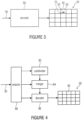
- FIG. 2 shows the encoder as comprising a subdivider 72 configured to subdivide the picture 20 into blocks 40, a merger 74 configured to merge the block 40 into groups of one or more sample sets as outlined above, an encoder or encoding stage 76, configured to encode the picture 20 using coding parameters varying across the picture 20 in units of the groups of sample sets, and a stream generator 78.
- the encoder 76 is configured to encode the picture 20 by predicting the picture 20 and encoding a prediction residual for predetermined blocks. That is, encoder 76 encodes, as described above, the prediction residual not for all blocks 40. Rather, some of them have the skip mode activated.
- the stream generator 78 is configured to insert the prediction residual and the coding parameters into the bitstream 30, along with one or more syntax elements for each of at least a subset of blocks 40, signaling whether the respective block 40 is merged into one of the groups along with another block or not and whether the respective block uses skip mode or not.
- the subdivision information underlying the subdivision of subdivider 72 may also be encoded into bitstream 30 for picture 20 by stream generator 78. This is indicated by a dashed line in Fig. 2 .
- the merge decision by merger 74 and the skip mode decision performed by encoder 76 is, as outlined above, commonly encoded into bitstream 30 by stream generator 78 such that one of the possible states of the one or more syntax elements of a current block 40 signalizes that the respective block is to be merged into one of the groups of blocks along with another block of picture 20 and has no prediction residual encoded and inserted into bitstream 30.
- the stream generator 78 may, for example, use entropy coding in order to perform the insertion.
- the subdivider 72 may be responsible for the subdivision of the picture 20 into the blocks 40 as well as the optional further partitioning into partitions 50 and 60, respectively.
- the merger 74 is responsible for the above-outlined merge decision while the encoder 76 may, for example, decide on the skip mode for the blocks 40. Naturally, all of these decisions influence the rate/distortion measure in combination, and accordingly apparatus 10 may be configured to try out several decision options in order to ascertain which option is to be preferred.
- a decoder 80 according to an embodiment is described with respect to Fig. 3 .
- the decoder 80 of Fig. 3 is configured to decode the bitstream 30 which, as described above, has picture 20 encoded therein.
- the decoder 80 is configured to be, for a current sample set or block 40, commonly responsive to the aforementioned flag within the bitstream 30 as to a first decision whether the coding parameters associated with the current block 40 are to be set according to a merge candidate or to be retrieved from the bitstream 30, and a second decision whether the current block 40 of the picture 20 is to be reconstructed merely based on a prediction signal depending on the coding parameters associated with the current block 40, without any residual data, or to be reconstructed by refining the prediction signal depending on the coding parameters associated with the current block 40 by means of residual data within the bitstream 30.
- the decoder 80 may be configured to perform the subdivision of picture 40 into blocks 40. This subdivision may be known to the decoder 80 by default, or decoder 80 may be configured to extract respective subdivision information from bitstream 30. Whenever a block 40 is merged, decoder 80 may be configured to obtain the coding parameters associated with that block 40 by setting the coding parameters thereof according to a merge candidate. In order to determine the merge candidate, the decoder 80 may perform the above-outlined determination of the set or list of merge candidates in exactly the same manner as the encoder did.
- decoder 80 may also be configured to subject blocks 40 to a partitioning in accordance with one of the supported partitioning patterns. Naturally, one of these partitioning patterns may involve a non-partitioning mode according to which a block 40 is not further partitioned.
- decoder 80 may be configured to reconstruct the current block 40 merely based on the prediction signal rather than a combination thereof with any residual signal. In other words, decoder 80 suppresses in that case residual data extraction for the current block 40 and merely reconstructs the picture 20 within the current block 40 by use of the prediction signal derived from the coding parameters of the current block. As was also already described above, decoder 80 may interpret the common state of the flag also as a signalization for the current block 40 that this block is an inter predicted block and/or a block not further partitioned.
- the decoder 80 may be configured such that same obtains the coding parameters associated with a current block 40 by setting these coding parameters according to a merge candidate, and reconstructs the current block 40 of the picture 20 merely based on a prediction signal depending on the coding parameters of the current block 40 without any residual data if the flag in question of the current block 40 within the bitstream 30 signals that the coding parameters associated with the current block 40 are to be set using merging.
- the decoder 80 may be responsive to another flag within the bitstream 30 such that the decoder 80, depending on this other flag, obtains the coding parameters associated with the current block by setting same according to a respective merge candidate, obtains residual data for the current block from the bitstream 30 and reconstructs the current block 40 of the picture 20 based on the prediction signal and the residual data, or extracts the coding parameters associated with the current block 40 from the bitstream 30, obtains residual data for the current block 40 from the bitstream 30 and reconstructs the current block 40 of the picture 20 based on the prediction signal and the residual data.
- the decoder 80 may be configured to expect the existence of the other flag within bitstream 30 only in case of the first flag not assuming the commonly signaling state concurrently signaling the activation of the merging and the skip mode. Only then, the decoder 80 extracts the other flag from the bitstream in order to ascertain whether merging shall take place without the skip mode.
- the decoder 80 could alternatively be configured to await another third flag within bitstream 30 for the current block 40 in case of the second flag signaling the deactivation of merging, with this third flag signaling skip mode activation or deactivation.
- Fig. 4 shows a possible implementation of the apparatus for decoding of Fig. 3 .
- Fig. 4 shows an apparatus for decoding, i.e. a decoder 80, which comprises a subdivider 82 configured to subdivide the picture 20 encoded into bitstream 30 into blocks 40, a merger 84 configured to merge the blocks 40 into groups of one or more blocks each, a decoder 86 configured to decode or reconstruct the picture 20 using coding parameters varying across the picture 20 in units of the groups of sample sets and an extractor 88.
- a decoder 80 which comprises a subdivider 82 configured to subdivide the picture 20 encoded into bitstream 30 into blocks 40, a merger 84 configured to merge the blocks 40 into groups of one or more blocks each, a decoder 86 configured to decode or reconstruct the picture 20 using coding parameters varying across the picture 20 in units of the groups of sample sets and an extractor 88.
- the decoder 86 is also configured to decode the picture 20 by predicting the picture 20, decoding a prediction residual for predetermined blocks 40 and combining the prediction residual and a prediction resulting from predicting the picture 20, for the predetermined blocks 40, i.e. those having the skip mode switched off.
- the extractor 88 is configured to extract the prediction residual and the coding parameters from the bitstream 30, along with one or more syntax elements for each of at least a subset of the blocks 40, signaling whether the respective block 40 is to be merged into one of the groups along with another block 40 or not, wherein the merger 84 is configured to perform the merging responsive to the one or more syntax elements, wherein one of the possible states of the one or more syntax elements signalizes that the respective block 40 is to be merged into one of the groups of blocks along with another block 40 and has no prediction residual encoded and inserted into the bitstream 30.
- the subdivider 82 acts like subdivider 72 in order to restore the subdivision generated by subdivider 72.
- Subdivider 82 knows about the subdivision of picture 20 either by default or extracts subdivision information from bitstream 30 via extractor 88.
- merger 84 forms the merging of the blocks 40 and is activated with regard to blocks 40 and block portions via the above-outlined signaling within bitstream 30.
- Decoder 86 performs the generation of the prediction signal of picture 20 using the coding parameters within bitstream 30. In case of merging, decoder 86 copies the coding parameters of a current block 40 or a current block partition from neighboring blocks/partitions or otherwise sets the coding parameters thereof according to the merge candidate.
- the extractor 88 is configured to interpret one of the possible states of a flag or syntax element for a current block as a signal that concurrently signals the activation of the merging and the skip mode. Concurrently, extractor 88 may interpret the state to also signal a predetermined one among the supported partitioning patterns for the current block 40.
- the predetermined partitioning pattern may be the non-partitioning mode according to which block 40 remains unpartitioned and thus forms a partition itself. Accordingly, extractor 88 expects bitstream 30 to comprise partitioning information signaling the partitioning of block 40 merely in case of the respective flag or syntax element not assuming the concurrently signaling state.
- the partitioning information may be conveyed within bitstream 30 via a syntax element which, concurrently, controls the coding mode of the current block 40, i.e. divide up blocks 40 into ones being inter coded and ones being intra coded.
- the commonly signaling state of the first flag/syntax element may also be interpreted as a signalization of the inter prediction coding mode.
- extractor 88 may extract another merging flag from bitstream in case of the first flag/syntax element for block 40 not assuming the commonly signaling state concurrently signaling activation of the merging and the skip mode.
- the skip mode may inevitably be interpreted by extractor 88 to be switched off, and although merging may be activated by bitstream 30 individually for the partitions, the residual signal is extracted from bitstream 30 for this current block 40.
- bitstream 30 may signal one of supported partitioning patterns for a current block 40 of picture 20.
- the decoder 80 may be configured to, if the signaled one of the supported partitioning pattern specifies a subdivision of the current block 40 into two or more partitions 50 and 60, remove for all partitions except the first partition 50 of the partitions in coding order 70, i.e. for partition 60 in the illustrated example of Figs.
- the decoder 80 may be configured to, if a number of the non-removed coding parameter candidates is non-zero, set coding parameters associated with the respective partition 60 depending on one of the non-removed parameter candidates. For example, the decoder 80 sets the coding parameters of partition 60 so as to be equal to one of the non-removed coding parameter candidate, with or without additional refinement and/or with or without scaling in accordance with a temporal distance to which the coding parameters refer, respectively.
- the coding parameter candidate to merge with out of the non-removed candidates may have another reference picture index associated therewith than a reference picture index explicitly signaled within the bitstream 30 for partition 60.
- the coding parameters of the coding parameter candidates may define motion vectors, each related to a respective reference picture index, and the decoder 80 may be configured to scale the motion vector of the finally chosen non-removed coding parameter candidate in accordance with the ratio between both reference picture indices.
- the coding parameters being subject to merging would encompass the motion parameters, whereas reference picture indices would be separate therefrom.
- the reference picture indices could also be a part of the coding parameters being subject to merging.
- the decoder 80 and the encoder 10 may be configured to support intra and inter prediction modes for the current block 40 and perform merging merely in case of the current block 40 being coded in inter prediction mode. Accordingly, merely the coding/prediction parameters of such inter-predicted previously coded partitions may be used to determine/construct the candidate list.
- the coding parameters may be prediction parameters and the decoder 80 may be configured to use the prediction parameters of the partitions 50 and 60 in order to derive a prediction signal for the respective partition.
- the encoder 10 performs the derivation of the prediction signal in the same way, too.
- the encoder 10 additionally sets the prediction parameters along with all the other syntax elements within bitstream 30 in order to achieve some optimization in a suitable optimization sense.
- the encoder may be configured to insert an index to a (non-removed) coding parameter candidate merely in case the number of (non-removed) coding parameter candidate for a respective partition is greater than one.
- the decoder 80 may be configured to, depending on the number of (non-removed) coding parameter candidates for, for example, partition 60, merely expect the bitstream 30 to comprise a syntax element specifying which of the (non-removed) coding parameter candidate is employed for merging, if the number of (non-removed) coding parameter candidates is greater than one.
- the case of the candidate set getting smaller in number than two could be generally excluded from occurring by extending, as described above, the list/set of candidates using combined coding parameters, i.e. parameters having been derived by combination of the coding parameters of more than one - or more than two - previously coded partitions, with restricting the performance of the candidate set reduction to those candidates having been obtained by adopting, or derivation from, the coding parameters of exactly one previously coded partition.
- the opposite is possible as well, i.e. generally removing all coding parameter candidates having the same value as those of the partition resulting in another supported partitioning pattern.
- the decoder 80 acts as encoder 10 does. That is, decoder 80 may be configured to determine the set of merge candidates for the partition or the partitions of a block 40 based on coding parameters associated with previously decoded partitions. That is, a coding order may not only be defined among the partitions 50 and 60 of a respective block 40, but also among blocks 40 of picture 20 itself. All the partitions having been coded prior to partition 60 may, thus, serve the basis for the determination of the set of merge candidates for any of the subsequent partitions, such as partition 60 in case of Fig. 3 . As is also described above, the encoder and decoder may restrict the determination of the set of merge candidates to partitions in a certain spatial and/or temporal neighborhood.
- the decoder 80 may be configured to determine the set of merge candidates based on the coding parameters associated with previously decoded partitions neighboring the current partition, wherein such partitions may lay outside and inside the current block 40.
- the determination of merge candidates may also be performed for the first partition in coding order. Merely the removal may be left away.
- the decoder 80 may be configured to determine the set of coding parameter candidates for the respective non-first partition 60 out of an initial set of previously decoded partitions, excluding ones being coded in an intra prediction mode.
- the decoder 80 may be configured to recover the subdivision of picture 20 into such coding blocks 40 according to the subdivision information in the bitstream 30.
- the residual signal for current block 40 may be transmitted via bitstream 30 in a granularity which may differ from the granularity defined by the partitions with regard to the coding parameters.
- encoder 10 of Fig. 1 may be configured to subdivide the block 40 into one or more transform blocks in a way parallel to, or independent from, the partitioning into partitions 50 and 60.
- the encoder may signalize the respective transform block subdivision for block 40 by way of further subdivision information.
- the decoder 80 may be configured to recover this further subdivision of block 40 into one or more transform blocks according to the further subdivision information in the bitstream, and to derive a residual signal of the current block 40 from the bitstream in units of these transform blocks.
- the significance of the transform block partitioning may be that the transform, such as DCT, in the encoder and the corresponding inverse transform such as IDCT in the decoder are performed within each transform block of block 40 individually.
- the encoder 10 then combines, such as adds, the prediction signal derived by applying the coding parameters at the respective partitions 50 and 60, and the residual signal, respectively.
- the residual coding may not involve any transform and inverse transform respectively, and that the prediction residuum is coded in the spatial domain instead, for example.
- FIG. 5 shows exemplarily as to how encoder 10 may be constructed internally.
- encoder 10 may comprise a subtracter 108, a transformer 100, and a bitstream generator 102, which may, as indicated in Fig. 5 , perform an entropy coding.
- Elements 108, 100 and 102 are serially connected between an input 112 receiving picture 20, and an output 114 outputting the aforementioned bitstream 30.
- subtractor 108 has its non-inverting input connected to input 112 and transformer 100 is connected between an output of subtractor 108 and a first input of bitstream generator 102 which, in turn, has an output connected to output 114.
- the encoder 10 of Fig. 5 further comprises an inverse transformer 104 and an adder 110 serially connected, in the order mentioned, to the output of transformer 100.
- Encoder 10 further comprises a predictor 106, which is connected between an output of adder 110 and a further input of adder 110 and the inverting input of subtractor 108.
- Predictor 106 predicts portions of picture 20 with the result of the prediction, i.e., the prediction signal, being applied to the inverting input of subtracter 108.
- the output of subtractor 108 represents the difference between the prediction signal and the respective portion of picture 20, i.e. a residual signal.
- the residual signal is subject to transform coding in transformer 100. That is, transformer 100 may perform a transformation, such as a DCT or the like, and a subsequent quantization on the transformed residual signal, i.e. the transform coefficients, so as to obtain transform coefficient levels.
- the inverse transformer 104 reconstructs the final residual signal output by transformer 100 to obtain a reconstructed residual signal which corresponds to the residual signal input into transformer 100 except for the information loss due to the quantization in transformer 100.
- the addition of the reconstructed residual signal and the prediction signal as output by predictor 106 results in a reconstruction of the respective portion of picture 20 and is forwarded from the output of adder 110 to the input of predictor 106.
- Predictor 106 operates in different modes as described above, such as an intra prediction mode, inter prediction mode and the like. Prediction mode and the corresponding coding or prediction parameters applied by predictor 106 in order to obtain the prediction signal, are forwarded by predictor 106 to entropy encoder 102 for insertion into the bitstream.
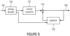
- the decoder 80 may comprise a bitstream extractor 150 which may, as shown in Fig. 6 , be implemented as an entropy decoder, an inverse transformer 152 and an adder 154, which are, in the order mentioned, connected between an input 158 and an output 160 of the decoder.
- the decoder of Fig. 6 comprises a predictor 156 connected between an output of adder 154 and a further input thereof.
- the entropy decoder 150 is connected to a parameter input of predictor 156.
- the entropy decoder 150 is for extracting all the information contained in the bitstream 30.
- the entropy coding scheme used may be variable length coding or arithmetic coding.
- entropy decoder 150 recovers from the bitstream transformation coefficient levels representing the residual signal and forwards same to the inverse transformer 152.
- entropy decoder 150 acts as the above-mentioned extractor 88 and recovers from the bitstream all the coding modes and associated coding parameters and forwards same to predictor 156.
- the partitioning information and merging information is extracted from the bitstream by extractor 150.
- the inversely transformed, i.e., reconstructed residual signal and the prediction signal as derived by predictor 156 are combined, such as added, by adder 154 which, in turn, outputs the thus-recovered reconstructed signal at output 160 and forwards same to the predictor 156.
- elements 152, 154 and 156 functionally correspond to elements 104, 110 and 106 of Fig. 5 .
- Fig. 7a shows a portion out of a picture 20.
- encoder and decoder are configured to firstly subdivide picture 20 into tree-root blocks 200.
- One such tree-root block is shown in Fig. 7a .
- the subdivision of picture 20 into tree-root blocks is done regularly in rows and columns as illustrated by dotted lines.
- the size of the tree-root blocks 200 may be selected by the encoder and signaled to the decoder by bitstream 30. Alternatively, the size of these tree-root blocks 200 may be fixed by default.
- the tree-root blocks 200 are subdivided by use of quad-tree partitioning in order to yield the above-identified blocks 40 which may be called coding blocks or coding units. These coding blocks or coding units are drawn with thin solid lines in Fig. 7a .
- the encoder accompanies each tree-root block 200 with subdivision information and inserts the subdivision information into the bitstream. This subdivision information indicates as to how the tree-root block 200 is to be subdivided into blocks 40.
- each block 40 - or each block having a certain prediction mode such as inter prediction mode - is accompanied by partitioning information as to which supported partitioning pattern is used for the respective block 40.
- the aforementioned flag/syntax element may, when assuming the commonly signaling state, concurrently also signal one of the supported partitioning modes for the respective block 40 so that the explicit transmission of another partitioning information for this block 40 may be suppressed at the encoder side and not be expected, accordingly, at the decoder side.
- the non-partitioning mode has been chosen so that the coding block 40 spatially coincides with the corresponding partition.
- the coding block 40 is, concurrently, a partition having a respective set of prediction parameters associated therewith.
- the sort of prediction parameters depends on the mode associated with the respective coding block 40.
- Other coding blocks are exemplarily shown to be further partitioned.
- the coding block 40 at the top right-hand corner of the tree-root block 200 for example, is shown to be partitioned into four partitions, whereas the coding block at the bottom right-hand corner of the tree-root block 200 is exemplarily shown to be vertically subdivided into two partitions.
- Fig. 7a also shows the coding order among the partitions thus defined. As shown, a depth-first traversal order is used. Across the tree-root block borders, the coding order may be continued in a scan order according to which the rows of tree-root blocks 200 are scanned row-wise from top to bottom of picture 20. By this measure, it is possible to have a maximum chance that a certain partition has a previously coded partition adjacent to its top border and left-hand border.
- Each block 40 - or each block having a certain prediction mode such as inter prediction mode - may have a merge switch indicator within the bitstream indicating as to whether merging is activated for the corresponding partitions therein or not.
- partitioning of the blocks into partitions/prediction units could be restricted to a partitioning of maximally two partitions, with merely an exception of this rule being only made for the smallest possible block size of blocks 40. This could, in case of using quad-tree subdivision in order to obtain blocks 40, avoid redundancy between subdivision information for subdividing picture 20 into block 40 and partitioning information for subdividing block 40 into partitions. Alternatively, merely partitionings into one or two partitions could be allowed, including or not including asymmetric ones.
- Fig. 7b shows a subdivision tree. With solid lines, the subdivision of tree-root block 200 is illustrated, whereas dotted lines symbolize the partitioning of the leaf blocks of the quad-tree subdivisioning, which are the coding blocks 40. That is, the partitioning of the coding blocks represents a kind of extension of the quad-subdivision.
- each coding block 40 may be parallely subdivided into transform blocks so that transform blocks may represent a different subdivision of the respective coding block 40.
- transform blocks which are not shown in Figs. 7a and 7b , a transformation in order to transform the residual signal of the coding blocks may be performed separately.
- embodiments of the present application describe methods for reducing the side information rate in image and video coding applications by combined signaling of merging and the absence of residual data for sets of samples.
- the side information rate in image and video coding applications is reduced by combining syntax elements indicating the usage of merging schemes and syntax elements indicating the absence of residual data.
- the sample arrays associated with a picture are usually partitioned into particular sets of samples (or sample sets), which may represent rectangular or quadratic blocks or any other collection of samples including arbitrarily shaped regions, triangles, or any other shapes.
- the subdivision of the samples arrays may be fixed by the syntax or the subdivision is (at least partly) signaled inside the bitstream.
- the syntax usually allows only a limited number of choices resulting in simple partitioning such as the subdivision of blocks into smaller blocks.
- An often used partitioning scheme is the partitioning of square block into four smaller square blocks, or into two rectangular blocks of the same size, or into two rectangular blocks of different sizes, where the actually employed partitioning is signaled inside the bitstream.
- the sample sets are associated with particular coding parameters, which may specify prediction information or residual coding modes, etc.
- a partitioning is often done for the purpose of motion representation. All samples of a block (inside a partitioning pattern) are associated with the same set of motion parameters, which may include parameters specifying the type of prediction (e.g., list 0, list 1, or bi-prediction; and/or translational or affine prediction or a prediction with a different motion model), parameters specifying the employed reference pictures, parameters specifying the motion with respect to the reference pictures (e.g., displacement vectors, affine motion parameter vectors, or motion parameter vectors for any other motion model), which are usually transmitted as a difference to a predictor, parameters specifying the accuracy of motion parameters (e.g., half-sample or quarter-sample accuracy), parameters specifying the weighting of the reference sample signal (e.g., for the purpose of illumination compensation), or parameters specifying the interpolation filter that is employed for deriving the motion compensated prediction signal of the current block
- this invention presents a method and particular embodiments for merging two or more sample sets into so-called groups of sample sets. All sample sets of such a group share the same coding parameters, which can be transmitted together with one of the sample sets in the group. By doing so, the coding parameters do not need to be transmitted for each sample set of the group of sample sets individually, but instead the coding parameters are transmitted only once for the whole group of sample sets.
- an additional refinement for one or more of the coding parameters can be transmitted for one or more of the sample sets of a group of sample sets.
- the refinement can be either applied to all sample sets of a group or only to the sample set for which it is transmitted.
- Some embodiments of the present invention combine the merging process with a partitioning of a block into various sub-blocks 50, 60 (as mentioned above).
- image or video coding systems support various partitioning patterns for a block 40.
- a square block can be either not be partitioned or it can be partitioned into four square blocks of the same size, or into two rectangular blocks of the same size (where the square block can be vertically or horizontally divided), or into rectangular blocks of different sizes (horizontally or vertically).
- the described exemplary partition patterns are illustrated in Fig. 8 .
- the partitioning may involve even more than one level of partitioning.
- the square sub-blocks may optionally also be further partitioned using the same partitioning patterns.
- the same pattern can also be signaled by sending a syntax element that specifies that this block is, for example, subdivided into two vertically (or horizontally) aligned rectangular blocks 50, 60. Then we can transmit merging information that specify that the second of these rectangular blocks is merged with the first rectangular block, which results in exactly the same partitioning as when we signal that the block is not further divided.
- the same can also be achieved by first specifying that the block is subdivided in four square sub-blocks and then transmit merging information that effectively merges all these four blocks. This concept is clearly suboptimal (since we have different codewords for signaling the same thing).
- Some embodiments of the present invention reduce the side information rate and thus increase the coding efficiency for a combination of the concept of merging with the concept of providing different partitioning patterns for a block. If we look at the example partitioning patterns in Fig. 8 , the "simulation" of the not further divided block by any of the partitioning patterns with two rectangular blocks can be avoided when we forbid (i.e., exclude from the bitstream syntax specification) the case that a rectangular block is merged with a first rectangular block.
- the same concept is also employed to the partitioning pattern that divides a square block into four smaller square blocks.
- the sending of merging flags is adapted in a way that neither the partitioning pattern that specifies no subdivision nor any of the two partitioning patterns specify a subdivision into two rectangular blocks of the same size can be achieved by a combination of merging flags.
- the merging concept is in some sense similar to the SKIP or DIRECT modes that are found in video coding designs.
- SKIP/DIRECT modes basically no motion parameters are transmitted for a current block, but are inferred from a spatial and/or temporal neighborhood.
- a list of motion parameter candidates reference frame indices, displacement vectors, etc.
- an index into this list is transmitted that specifies which of the candidate parameters is chosen.
- a separate candidate can be signaled for each reference list.
- Possible candidates may include the block to the top of the current block, the block to the left of the current block, the block to the top-left of the current block, the block to the top-right of the current block, the median predictor of various of these candidates, the co-located block in one or more previous reference frames (or any other already coded block, or a combination obtained from already coded blocks).
- Combining SKIP/DIRECT with the merge concept means that a block can be coded using either a SKIP/DIRECT or a merging mode.
- SKIP/DIRECT and merging concepts are similar there are differences between the two concepts which are explained in more detail in section 1.
- the main difference between SKIP and DIRECT is that the SKIP mode further signals that no residual signal is transmitted.
- a flag is transmitted that signals whether a block contains non-zero transform coefficient levels.
- the embodiments described above and below combine the signaling whether a sample set uses the coding parameters of another sample set and the signaling whether no residual signal is transmitted for the block.
- the combined flag indicates that a sample set uses coding parameters of another sample set and that no residual data is transmitted. For this case only one flag, instead of two, needs to be transmitted.
- some embodiments of the present invention also provide an encoder with a greater freedom for creating a bitstream, since the merging approach significantly increases the number possibilities for selecting a partitioning for the sample arrays of a picture without introducing redundancy in the bitstream. Since the encoder can choose between more options, e.g., for minimizing a particular rate-distortion measure, the coding efficiency can be improved.
- some of the additional patterns that can be represented by a combination of sub-partitioning and merging e.g., the patterns in Fig. 9
- the encoder could first determine the best subdivision of the sample arrays (as in state-of-the-art coding schemes). And then it could check for each sample set, whether a merging with another sample set or another group of sample sets reduces a particular rate-distortion cost measure.
- the prediction parameters associated with the merged group of sample sets can be re-estimated (e.g., by performing a new motion search) or the prediction parameters that have already be determined for the current sample set and the candidate sample set (or group of sample sets) for merging could be evaluated for the considered group of sample sets.
- a particular rate-distortion cost measure could be evaluated for additional candidate groups of sample sets.
- some or all of the pattern that can be represented by a combination of partitioning and merging see Fig. 9 for example can be additionally tested.
- a specific motion estimation and mode decision process is carried out and the pattern which yields the smallest rate-distortion measure is selected.
- This process can also be combined with the low complexity process described above, so that for the resulting blocks it is additionally tested whether a merging with already coded blocks (e.g., outside the patterns of Fig. 8 and Fig. 9 ) yields a decrease in a rate-distortion measure.
- the pictures or particular sets of sample arrays for the pictures may be decomposed into blocks, which are associated with particular coding parameters.
- the pictures usually consist of multiple sample arrays.
- a picture may also be associated with additional auxiliary samples arrays, which may, for example, specify transparency information or depth maps.
- the sample arrays of a picture can be grouped into one or more so-called plane groups, where each plane group consists of one or more sample arrays.
- the plane groups of a picture can be coded independently or, if the picture is associated with more than one plane group, with prediction from other plane groups of the same picture.
- Each plane group is usually decomposed into blocks.
- the blocks (or the corresponding blocks of sample arrays) are predicted by either inter-picture prediction or intra-picture prediction.
- the blocks can have different sizes and can be either quadratic or rectangular.
- the partitioning of a picture into blocks can be either fixed by the syntax, or it can be (at least partly) signaled inside the bitstream.
- syntax elements are transmitted that signal the subdivision for blocks of predefined sizes. Such syntax elements may specify whether and how a block is subdivided into smaller blocks and being associated with coding parameters, e.g. for the purpose of prediction.
- Fig. 8 An example of possible partitioning patterns is shown in Fig. 8 .
- the decoding of the associated coding parameters is specified in a certain way.
- all samples in a block are predicted using the same set of prediction parameters, such as reference indices (identifying a reference picture in the set of already coded pictures), motion parameters (specifying a measure for the movement of a blocks between a reference picture and the current picture), parameters for specifying the interpolation filter, intra prediction modes, etc.
- the motion parameters can be represented by displacement vectors with a horizontal and vertical component or by higher order motion parameters such as affine motion parameters consisting of six components.
- more than one set of particular prediction parameters are associated with a single block.
- a single intermediate prediction signal for the block (or the corresponding blocks of sample arrays) is generated, and the final prediction signal is build by a combination including superimposing the intermediate prediction signals.
- the corresponding weighting parameters and potentially also a constant offset (which is added to the weighted sum) can either be fixed for a picture, or a reference picture, or a set of reference pictures, or they can be included in the set of prediction parameters for the corresponding block.
- the difference between the original blocks (or the corresponding blocks of sample arrays) and their prediction signals, also referred to as the residual signal is usually transformed and quantized.
- a two-dimensional transform is applied to the residual signal (or the corresponding sample arrays for the residual block).
- the blocks (or the corresponding blocks of sample arrays), for which a particular set of prediction parameters has been used can be further split before applying the transform.
- the transform blocks can be equal to or smaller than the blocks that are used for prediction. It is also possible that a transform block includes more than one of the blocks that are used for prediction. Different transform blocks can have different sizes and the transform blocks can represent quadratic or rectangular blocks. In the above example for Figs. 1-7 , it has been noted that it is possible that the leaf nodes of the first subdivision, i.e.
- the coding blocks 40 may parallely be further partitioned into the partition defining the granularity of coding parameters, on the one hand, and the transform blocks onto which the two-dimensional transform is applied individually, on the other hand. After transform, the resulting transform coefficients are quantized and so-called transform coefficient levels are obtained.
- the transform coefficient levels as well as the prediction parameters and, if present, the subdivision information is entropy coded.
- the coding parameters for the transform blocks are called residual parameters.
- the residual parameters as well as the prediction parameters and, if present, the subdivision information may be entropy coded.
- CBF coded block flag
- the possibilities for subdividing a picture (or a plane group) into blocks that are provided by the syntax are very limited. Usually, it can only be specified whether and (potentially how) a block of a predefined size can be subdivided into smaller blocks.
- the largest block size in H.264 is 16x16.
- the 16x16 blocks are also referred to as macroblocks and each picture is partitioned into macroblocks in a first step. For each 16x16 macroblock, it can be signaled whether it is coded as 16x16 block, or as two 16x8 blocks, or as two 8x16 blocks, or as four 8x8 blocks.
- each of these 8x8 blocks can be either coded as one 8x8 block, or as two 8x4 blocks, or as two 4x8 blocks, or as four 4x4 blocks.
- the small set of possibilities for specifying the partitioning into blocks in state-of-the-art image and video coding standards has the advantage that the side information rate for signaling the subdivision information can be kept small, but it has the disadvantage that the bit rate required for transmitting the prediction parameters for the blocks can become significant as explained in the following.
- the side information rate for signaling the prediction information does usually represent a significant amount of the overall bit rate for a block. And the coding efficiency could be increased when this side information is reduced, which, for instance, could be achieved by using larger block sizes.
- the partitioning patterns depicted in Fig. 8 can be provided for square blocks of all sizes (or selected sizes).
- Real images or pictures of a video sequence consist of arbitrarily shaped objects with specific properties.
- such objects or parts of the objects are characterized by a unique texture or a unique motion.
- the same set of prediction parameters can be applied for such an object or part of an object.
- the object boundaries usually don't coincide with the possible block boundaries for large prediction blocks (e.g., 16x16 macroblocks in H.264).
- An encoder usually determines the subdivision (among the limited set of possibilities) that results in the minimum of a particular rate-distortion cost measure.
- the coding efficiency could be increased when the syntax is extended in a way that it does not only allow to subdivide a block, but also to merge two or more of the blocks that are obtained after subdivision. As a result, one would obtain a group of blocks that are coded with the same prediction parameters. The prediction parameters for such a group of blocks need to be coded only once.
- the coding parameters for the current clock 40 are not transmitted provided that merging takes place. That is, the encoder does not transmit the coding parameters associated with the current block, and the decoder does not expect the bitstream 30 to contain coding parameters for the current block 40.
- merely refinement information may be conveyed for the merged current block 40.
- a determination of a candidate set and the reduction thereof as well as the merging and so forth is also performed for the other coding blocks 40 of picture 20.
- the coding blocks somehow form groups of coding blocks along a coding chain, wherein the coding parameters for these groups are transmitted within the bitstream in full merely once.
- the described merging does result in increased coding efficiency.
- the described syntax extension (for the merging) provides the encoder with additional freedom in selecting the partitioning of a picture or plane group into blocks, without introducing redundancy.
- the encoder is not restricted to do the subdivision first and then to check whether some of the resulting blocks have the same set of prediction parameters.
- the encoder could first determine the subdivision as in state-of-the-art coding techniques. And then it could check for each block, whether a merging with one of its neighbor blocks (or the associated already determined group of blocks) reduces a rate-distortion cost measure.
- the prediction parameters associated with the new group of blocks can be re-estimated (e.g., by performing a new motion search) or the prediction parameters that have already been determined for the current block and the neighboring block or group of blocks could be evaluated for the new group of blocks.
- An encoder can also directly check (a subset of) the patterns that are provided by a combination of splitting and merging; i.e., the motion estimation and mode decision can be done with the resulting shapes as already mentioned above.
- the merging information can be signaled on a block basis. Effectively, the merging could also be interpreted as inference of the prediction parameters for a current block, where the inferred prediction parameters are set equal to the prediction parameters of one of the neighboring blocks.
- SKIP/DIRECT modes in the state-of-the-art video coding standard in H.264, which are selected on a picture level: the temporal direct mode and the spatial direct mode. Both direct modes are only applicable to B pictures.
- temporal direct mode the reference index for reference picture list 0 is set equal to 0 and the reference index for reference picture list 1 as well as the motion vectors for both reference lists are derived based on the motion data of the co-located macroblock in the first reference picture in reference picture list 1.
- the temporal DIRECT mode uses the motion vector from the temporal collocated block and scales the motion vector according to the temporal distance between the current and the collocated block.
- the reference indexes and motion vectors for both reference picture lists are basically inferred based on the motion data in a spatial neighborhood.
- the reference indexes are chosen as the minimum of the corresponding reference indexes in the spatial neighborhood and each motion vector component is set equal to the median of the corresponding motion vector components in the spatial neighborhood.
- the SKIP mode can only be used for coding 16x16 macroblocks in H.264 (in P and B pictures) and the DIRECT mode can be used for coding 16x16 macroblocks or 8x8 sub-macroblocks.
- merging In contrast to the DIRECT mode, if merging is applied to a current block, all prediction parameters may be copied from the block the current block is merged with. Merging can also be applied to arbitrary block sizes resulting in the above-mentioned more flexible partitioning patterns where all samples of one pattern are predicting using the same prediction parameters.
- the basic idea of the embodiments outlined above and below is to reduce the bit rate that is required for transmitting the CBF flags by combining the merge and CBF flags. If a sample set uses merging and no residual data is transmitted, one flag is transmitted signaling both.
- particular sets of samples (which may represent rectangular or quadratic blocks or arbitrarily shaped regions or any other collection of samples) are usually associated with a particular set of coding parameters.
- the coding parameters are included in the bitstream.
- the coding parameters may represent prediction parameters, which specify how the corresponding set of samples is predicted using already coded samples.
- the partitioning of the sample arrays of a picture into sample sets may be fixed by the syntax or may be signaled by corresponding subdivision information inside the bitstream. Multiple partitioning patterns for a block may be allowed.
- the coding parameters for the sample sets are transmitted in a predefined order, which is given by the syntax.
- the possible set of values for the corresponding merging information may be adapted to the employed partitioning pattern, in a way that particular partitioning patterns cannot be represented by a combination of other partitioning patterns and corresponding merging data.
- the coding parameters for a group of sample sets need to be transmitted only once. Additional to the prediction parameters, residual parameters (such as transform and quantization side information and transform coefficient levels) may be transmitted. If the current sample set is merged, side information describing the merging process are transmitted. This side information will be further referred to as merging information.
- the merging information contains a combined, so called mrg_cbf, flag that is equal to 1 if the current sample set is merged and no residual data is transmitted. In this case no further coding parameters and residual parameters are transmitted. If the combined mrg_cbf flag is equal to 0, another flag indicating whether merging is applied or not is coded. Furthermore flags indicating that no residual parameters are transmitted are coded.
- the contexts for probability derivation (and VLC table switching) for syntax elements related to merging information can be chosen as a function of already transmitted syntax elements and/or decoded parameters (such as the combined mrg_cbf flag).
- the merging information containing a combined mrg_cbf flag is coded before coding parameters (e.g. prediction information and subdivision information).
- the merging information containing a combined mrg_cbf flag is coded after a subset of the coding parameters (e.g. prediction information and subdivision information). For every sample set, resulting from the subdivision information, merging information may be coded.
- mrg_cbf is called skip_flag.
- mrg_cbf could be called merge_skip in order to show that it is another version of skip related with block merging.
- the following preferred embodiments are described for sets of samples that represent rectangular and quadratic blocks, but it can be extended to arbitrarily shaped regions or other collections of samples in a straightforward way.
- the preferred embodiments describe combinations of syntax elements related to the merging scheme and syntax elements indicating the absence of residual data.
- Residual data may include residual side information as well as transform coefficient levels.
- the absence of residual data is specified by means of a coded block flag (CBF) but it can be expressed by other means or flags as well.
- CBF coded block flag
- the subsidiary merging activating flag is called mrg whereas later on, with respect to Fig. 11 to 13 , same is called merge_flag.
- merge_flag the merge index
- merge_idx the merge index
- up to three syntax elements are transmitted for specifying the merging information and the CBF.
- the first syntax element which is called mrg_cbf in the following, specifies whether the current set of samples is merged with another sample set and whether all corresponding CBFs are equal to 0.
- the mrg_cbf syntax element may only be coded if a derived set of candidate sample sets is not empty (after the potential removal of the candidates that would produce a partitioning that could be signaled by different partitioning pattern without merging). However, it may be guaranteed by default that the list of merge candidates never vanishes, that there is at least one or even at least two merge candidates available.
- the mrg_cbf syntax element is coded as follows.
- the second syntax element further called mrg specifics whether the current set of samples is merged with another sample set. If the mrg_cbf syntax element is equal to 1 the mrg syntax element is not coded and inferred to be equal to 1 instead. If the mrg_cbf syntax element is not present (because the derived set of candidate samples is empty), the mrg syntax element is also not present, but inferred to be equal to 0. However, it may be guaranteed by default that the list of merge candidates never vanishes, that there is at least one or even at least two merge candidates available
- the third syntax element which is only coded if the mrg syntax element is equal to 1 (or inferred to be equal to 1), specifies which of the sets of candidate sample sets is employed for merging.
- the mrg_idx syntax element is only coded if a derived set of candidate sample sets contains more than one candidate sample set.
- the mrg_idx syntax element is only coded if at least two sample sets of a derived set of candidate sample sets are associated with different coding parameters.
- the merge candidate list can even be fixed in order to decouple the parsing and the reconstruction to improve the parsing throughput and to be more robust in regard to information loss.
- the decoupling can be assured by using a fixed assignment of list entries and codewords. This would not necessitate to fix the length of the list.
- concurrently fixing the length of the list by adding additional candidates allows for compensating the coding efficiency loss of the fixed (longer) codewords.
- the merge index syntax element may only be transmitted if the list of candidates contains more than one candidate. This would require, however, to derive the list prior to parsing merge index, preventing to carry out these two processes in parallel.
- the merging information for a set of samples is coded after a subset of the prediction parameters (or, more generally, the particular coding parameters that are associated with the sample sets) has been transmitted.
- the subset of prediction parameters may consist of one or more reference picture indices or one or more components of a motion parameter vector or a reference picture index and one or more components of a motion parameter vector, etc.
- the mrg_cbf syntax element of the merging information is coded only for a reduced set of partitioning modes.
- a possible set of partitioning modes is presented in Fig. 8 .
- this reduced set of partitioning modes is limited to one and corresponds to the first partitioning mode (the top-left of the list in Fig. 8 ).
- the mrg_cbf is coded only if a block is not further partitioned.
- the mrg_cfb may be coded only for square blocks.
- the mrg_cbf syntax element of the merging information is coded only for one block of a partitioning where this partitioning is one of the possible partitioning modes shown in Fig. 8 , e.g. the partitioning mode with four blocks bottom left.
- the merging information of the first merged block contains the mrg_cbf syntax element for the complete partition.
- the merging information only contains the mrg syntax element specifying whether the current set of samples is merged with another sample set or not. The information whether residual data are present or not is inferred from the mrg_cbf syntax element coded in the first block.
- the merging information for a set of samples is coded before the prediction parameters (or, more generally, the particular coding parameters that are associated with the sample sets).
- the merging information containing the mrg_cbf, the mrg and the mrg_idx syntax element, is coded in a manner as described in the first preferred embodiment above.
- the prediction or coding parameters and the residual parameters are only transmitted if the merging information signals that the current set of samples is not merged with another set of samples and that the CBF, for at least one of the components, is equal to 1.
- the mrg_cbf syntax element specifies that the current block is merged and the CBFs for all components are equal to 0, there will be no more signalization needed after the merging information, for this current block.
- the syntax elements mrg_cbf, mrg, and mrg_idx are combined and coded as one or two syntax elements.
- mrg_cbf and mrg are combined into one syntax element, which specifies any of the following cases: (a) the block is merged and it doesn't contain residual data, (b) the block is merged and contains residual data (or may contain residual data), (c) the block is not merged.
- the syntax elements mrg and mrg_idx are combined into one syntax element.
- the combined syntax element specifies one of the following cases: the block is not merged, the block is merged with candidate 1, the block is merged with candidate 2, ..., the block is merged with candidate N.
- the syntax elements mrg_cfb, mrg, and mrg_idx are combined into one syntax element, which specifies one of the following cases (with N being the number of candidates): the block is not merged, the block is merged with candidate 1 and doesn't contain residual data, the block is merged with candidate 2 and doesn't contain residual data, ..., the block is merged with candidate N and doesn't contain residual data, the block is merged with candidate 1 and contains (or may contain) residual data, the block is merged with candidate 2 and contains (or may contain) residual data, ..., the block is merged with candidate N and contains (or may contain) residual data.
- the combined syntax elements may be transmitted with a variable length code or may be transmitted by arithm
- the SKIP/DIRECT modes may be supported for all or only particular block sizes and/or block shapes.
- a set of candidate blocks is used for the SKIP/DIRECT modes.
- the difference between SKIP and DIRECT is whether residual parameters are sent or not.
- the parameters (e.g., for prediction) of SKIP and DIRECT can be inferred from any of the corresponding candidates.
- a candidate index is coded, which signals which candidate is used to infer the coding parameters. If multiple predictions are combined to form the final prediction signal for the current block (as in bi-predictive blocks used in H.264 B-frames) every prediction can refer to a different candidate. Thus for every prediction a candidate index can be coded.
- the candidate list for SKIP/DIRECT may contain different candidate blocks than the candidate list for merge modes.
- An example is illustrated in Figure 10 .
- the candidate list may include the following blocks (the current block is denoted by Xi):
- both SKIP/DIRECT modes and block merging modes are supported.
- SKIP/DIRECT modes use the original set of candidates, set_mvp_ori.
- the merging information related to the block merging mode may contain the combined mrg_cbf syntax element.
- both SKIP/DIRECT mode and block merging modes are supported, but the SKIP/DIRECT modes use a modified set of candidates, set_mvp_comb.
- This modified set of candidates can be a particular subset of the original set set_mvp_ori.
- the modified set of candidates is composed of Corner blocks and a Collocated block.
- the modified set of candidates is only composed of the Collocated block. Further subsets are possible.
- the merging information containing the mrg_cbf syntax element is coded before the SKIP mode related parameters.
- the SKIP mode related parameters are coded before the merging information containing the mrg_cbf syntax element.
- DIRECT mode may not be activated (is not even present) and block merging has an extended set of candidates with SKIP mode replaced by mrg_cbf.
- the candidate list for block merging may contain different candidate blocks.
- An example is illustrated in Figure 10 .
- the candidate list may include the following blocks (the current block is denoted by Xi):
- position of candidates for block merging can be the same than the list of MVP in inter-prediction in order to save memory access.
- the list can be "fixed" in the manner outlined above in order to decouple the parsing and the reconstruction to improve the parsing throughput & to be more robust in regard to information loss.
- a flag is transmitted that signals whether or not all components (e.g., a luma and two chroma components) of the residual data are zero. This flag is not transmitted if mrg_cfb is equal to 1. In a particular configuration, this flag is not transmitted if mrg_cfb is equal to 0 and the syntax element mrg specifies that the block is merged.
- mrg_cfb syntax element if the mrg_cfb syntax element is equal to 0 (it signals that the block is either not merged or that it contains nonzero residual data), a separate syntax element for each component is transmitted that signals whether or not the residual data for the component are zero.
- One of the possible states of the one or more syntax elements signalizes that the respective sample set is to be merged into one of the disjoint sets along with another sample set and has no prediction residual encoded and inserted into the bitstream.
- the extractor may also be configured to extract subdivision information from the bitstream, and the subdivider is configured to subdivide the picture into sample sets responsive to the subdivision information.
- the extractor and the merger may, for example, be configured to sequentially step through the sample sets according to a sample set scan order, and to, for a current sample set,
- the one or more syntax elements for each of at least a subset of the sample sets may also signal with which of a set of predetermined candidate sample sets neighboring the respective sample set, the respective sample set is to be merged, if the respective sample set is to be merged into any one of the disjoint sets along with another sample set.
- the extractor may be configured to, if the one or more syntax elements does not signal that the respective sample set is to be merged into any of the disjoint sets along with another sample set, extract from the bitstream one or more further syntax elements (SKIP/DIRECT mode) signaling as to whether, and from which of a further set of predetermined candidate sample sets neighboring the respective sample set, at least a part of the coding parameters for the respective sample set is to be predicted.
- SKIP/DIRECT mode further syntax elements
- the set of predetermined candidate sample sets and the further set of predetermined candidate sample sets may be disjoint or intersect each other with respect to a minority of the predetermined candidate sample sets of the set of predetermined candidate sample sets and the further set of predetermined candidate sample sets, respectively.
- the extractor may also be configured to extract subdivision information from the bitstream, and the subdivider is configured to hierarchically subdivide the picture into sample sets responsive to the subdivision information, and the extractor is configured to sequentially step through child sample sets of a parent sample set, comprised by the sample sets into which the picture is sub-divided, and, for a current child sample set,
- a parent sample set (CU) is split into two child sample sets (PU). If, then, for the first PU, the first binary syntax element (merge_cbf) has the first binary state 1) the first PU uses merge and the first and the second PU (the whole CU) do not have residual data in the bitstream, and 2) for the second PU second binary syntax element (merge_flag, merge_idx) is signaled.
- the first binary syntax element (merge_cbf) has the first binary state 1) the first PU uses merge and the first and the second PU (the whole CU) do not have residual data in the bitstream, and 2) for the second PU second binary syntax element (merge_flag, merge_idx) is signaled.
- the first binary syntax element for the first PU has the second binary state
- the second binary syntax element (merge_flag, merge_idx) is signaled, and residual data is in the bitstream as well
- the first binary syntax element (merge_cbf) is signaled.
- merge_cbf is also signaled on a PU level, i.e. for successive child sample sets, if merge_cbf is in a secondary binary state for all previous child sample sets. If merge_cbf is in a first binary state for a successive child sample set, all child sample sets following this child sample set do not have residual data in the bitstream.
- merge_cbf is in a first binary state for the second PU meaning that the third and fourth PU in coding order do not have residual data in the bitstream but the first PU has or can have.
- the first and second binary syntax elements may be coded using context-adaptive variable length coding or context-adaptive (binary) arithmetic coding and the contexts for coding the syntax elements are derived based on the values for these syntax elements in already coded blocks.
- the syntax element merge _idx may only be transmitted if the list of candidates contains more than one candidate. This requires to derive the list prior to parsing merge index, preventing to carry out these two processes in parallel. To allow for an increased parsing throughput and to make the parsing process more robust with regard to transmission errors, it is possible to remove this dependency by using a fixed codeword for each index value and a fixed number of candidates. If this number may not be reached by a candidate selection, it is possible to derive ancillary candidates to complete the list. These additional candidates may include so-called combined candidates, which are built from motion parameters of possibly different candidates already in the list, and zero motion vectors
- the syntax for signaling which of the blocks of the candidate set is simultaneously adapted at encoder and decoder. If for example, 3 choices of blocks for merging are given, those three choices are only present in the syntax and are considered for entropy coding. The probabilities for all other choices are considered to be 0 and the entropy codec is adjusted simultaneously at encoder and decoder.
- the prediction parameters that are inferred as a consequence of the merging process may represent the complete set of the prediction parameters that are associated with a block or they may represent of subset of these prediction parameters (e.g., the prediction parameters for one hypothesis of a block for which multi-hypotheses prediction is used).
- the syntax elements related to the merging information are entropy coded using context modeling.
- Figs. 11-13 show different portions of a syntax which takes advantage of the above-outlined embodiments.
- picture 20 is firstly up-divided into coding tree blocks the picture content of which is coded using the syntax coding_tree shown in Fig. 11 .
- the quad-tree subdivision of the current coding tree block is signaled within syntax portion coding_tree by way of the flags called split_coding_unit_flag at mark 400.
- the tree-root block is subdivided as signaled by split_coding_unit_flag in a depth-first traversal order as shown in Fig. 7a . Whenever a leaf node is reached, same represents a coding unit which is coded right away using the syntax function coding_unit.
- the above-mentioned option is used according to which merging is merely usable for pictures for which the inter prediction mode is available. That is, intra-coded slices/pictures do not use merging anyway.
- the flag skip_flag is transmitted at 406 merely in case of a slice type being unequal to the intra-picture slice type, i.e. if the current slice which the current coding unit belongs to allows partitions to be inter coded.
- Merging relates, in accordance with the present embodiment, merely to the prediction parameters related to inter prediction.
- the skip_flag is signaled for the whole coding unit 40 and if skip_flag equals 1, this flag value concurrently signals to the decoder
- the function prediction_unit is called at 408 with denoting the current coding unit as being a prediction unit.
- the prediction type of the coding unit of the non-intra-picture slice is signaled at 410 by syntax element pred_type with, depending thereon, calling function prediction_unit for any partition of the current coding unit at, for example, 412 in case of the current coding unit being not further partitioned.
- Fig. 12 merely four different partitioning options are shown to be available, but the other partitioning options shown in Fig. 8 may be available as well.
- partitioning option PART_NxN is not available, but the others.
- the association between the names for the partitioning modes used in Fig. 12 to the partitioning options shown in Fig. 8 is indicated in Fig. 8 by respective subscripts below the individual partitioning options.
- the prediction type syntax element pred_type not only signals the prediction mode, i.e. intra or inter coded, but also the partitioning in case of inter coding mode.
- the inter-coding mode case is discussed further.
- the function prediction_unit is called for each partition, such as partitions 50 and 60 in the coding order mentioned above.
- the function prediction_unit starts with checking the skip_flag at 414. If the skip_flag is set, a merge_idx inevitably follows at 416.
- the check at step 414 is for checking as to whether the skip_flag related to the whole coding unit as signalized at 406 has been set or not. If not, a merge_flag is signalized again at 418, and if the latter is set, a merge_idx follows at 420 which indicates the merge candidate for the current partition. Again, merge_flag is signalized for the current partition at 418 merely in case of the current prediction mode of the current coding unit is an inter prediction mode (see 422).
- the prediction mode is signaled via pred_type at 410 whereupon, for each prediction unit, provided that pred_type signals that the inter coding mode is active (see 422), a merge specific flag, namely merge_flag, is individually transmitted for each partition followed, if merging is activated for the respective partition by a merge index merge_idx.
- the transmission of the prediction parameters in use for the current prediction unit at 424 is, in accordance with the present embodiment, performed merely in case of merging not being used for the present prediction unit, i.e. because merging is neither activated by skip_flag nor by the respective merge_flag of the respective partition.
- skip_flag 1 concurrently signals that no residual data is to be transmitted. This is derivable from the fact that the transmission of the residual data at 426 in Fig. 12 for the current coding unit merely takes place in case of skip_flag being equal to 0, as derivable from the fact that this residual data transmission in within the else option of if-clause 428 which checks the state of skip_flag immediately after its transmission.
- Figs. 11 to 13 has only been described under the assumption that entropy_coding_mode_flag equals 1.
- the possibility of concurrently signaling the activation of merging on the one hand and the skip mode on the other hand follows the above-outlined alternative according to which the commonly signaling state is merely one state among more than two states of a respective syntax element.
- entropy_coding_mode_flag 0 and the slice_type syntax element signals that the current tree-root block belongs to an inter coded slice, i.e. inter coding mode is available, then a syntax element cu_split_pred_part_mode is transmitted at 430, and this syntax element signals, as indicated via its name, information on the further subdivision of the current coding unit, the activation or deactivation of the skip mode, the activation or deactivation of merging and the prediction mode along with the respective partitioning information.
- Table 1 specifies the significance of the possible states of the syntax elements cu_split_pred_part_mode in case of the current coding unit have a size which is not the smallest one in the quad-tree subdivisioning of the current tree-root block.
- the possible states are listed in at the outermost left-hand column of table 1.
- table 1 refers to the case where the current coding unit does not have the smallest size, there is a state of cu_split_pred_part_mode, namely the state 0, which signals that the current coding unit is not an actual coding unit but has to be subdivided into further four units which are then traversed in depth-first traversal order as outlined by calling function coding_tree at 432 again.
- split_coding_unit_flag 1.
- one of the remaining possible states of cu_split_pred_part_mode represents the above-described commonly signaling state which concurrently signals that the current coding unit is subject to merging and has the skip mode activated, indicated by skip_flag equaling 1 in the third column of table 1, while concurrently signaling that no further partition of the current coding unit takes place, i.e. PART_2Nx2N is chosen as the partitioning mode.
- the merge_flag is signaled before hand rather than within the prediction_unit syntax.
- the inter prediction mode with other partitioning modes is signaled, with these partitioning modes partitioning the current coding unit into more than one partition.
- Table 2 shows the significance or semantics of the possible states of cu_split_pred_part_mode in case of the current coding unit having the smallest size possible in accordance with the quad-tree subdivision of the current tree-root block.
- same signals that no partitioning takes place i.e. partitioning mode PART_2Nx2N.
- Possible state 1 corresponds to possible state 2 of table 1 and the same applies to possible state 2 of table 2, which corresponds to possible state 3 of table 1.
- skip_flag [ x0 ][ y0 ] 1 specifies that for the current coding unit (see 40 in the figures), when decoding a P or B slice, no more syntax elements except the motion vector predictor indices (merge_idx) are parsed after skip_flag[ x0 ][ y0 ].
- skip_flag[ x0 ][ y0 ] 0 specifies that the coding unit is not skipped.
- the array indices x0, y0 specify the location ( x0, y0 ) of the top-left luma sample of the considered coding unit relative to the top-left luma sample of the picture (see 20 in the figures).
- skip_flag[ x0 ][ y0 ] When skip_flag[ x0 ][ y0 ] is not present, it shall be inferred to be equal to 0.
- cu_split_pred_part_mode [ x0 ][ y0 ] specifies split_coding_unit_flag and when the coding unit is not split the skip_flag[ x0 ][ y0 ], the merge_flag[ x0 ][ y0 ], PredMode and PartMode of a coding unit.
- the array indices x0 and y0 specify the location ( x0, y0 ) of the top-left luma sample of the coding unit relative to the top-left luma sample of the picture.
- merge_flag [ x0 ][ y0 ] specifies whether the inter prediction parameters for the current prediction unit (see 50 and 60 in the figures, i.e. the partition within coding unit 40) are inferred from a neighboring inter-predicted partition.
- the array indices x0, y0 specify the location ( x0, y0 ) of the top-left luma sample of the considered prediction block relative to the top-left luma sample of the picture.
- merge_idx [ x0 ][ y0 ] specifies the merging candidate index of the merging candidate list where x0, y0 specify the location ( x0, y0 ) of the top-left luma sample of the considered prediction block relative to the top-left luma sample of the picture.
- the merging candidates or the list of merging candidates is determined in this embodiment exemplarily using not only coding parameters or prediction parameters of spatially neighboring prediction unit/partitions, but rather, a list of candidates is also formed by using prediction parameters of temporally neighboring partitions of temporally neighboring and previously coded pictures. Moreover, combinations of prediction parameters of spatially and/or temporally neighboring prediction units/partitions are used and included into the list of merging candidates. Naturally, merely a subset thereof may be used.
- Fig. 14 shows one possibility of determining spatial neighbors, i.e. spatially neighboring partitions or prediction units.
- FIG. 14 shows exemplarily a prediction unit or partition 60 and pixels B 0 to B 2 and A 0 and A 1 which are located directly adjacent the border 500 of partition 60, namely B 2 being diagonally adjacent the top left pixel of partition 60, B1 being located vertically above and adjacent the top right-hand pixel of partition 60, B0 being located diagonally to the top right-hand pixel of partition 60, A1 being located horizontally to the left of, and adjacent the bottom left-hand pixel of partition 60, and A0 being located diagonally to the bottom left-hand pixel of partition 60.
- a partition that includes at least one of pixels B 0 to B 2 and A 0 and A 1 forms a spatial neighbor and the prediction parameters thereof form a merge candidate.
- the candidate N is removed from the candidate list if any of the following conditions is true (please see Fig. 8 for the partitioning mode PartMode and the corresponding partitioning index PartIdx indexing the respective partition inside the coding unit):
- position or location ( xP, yP ) denotes the uppermost pixel of the current partition/prediction unit. That is, in accordance with the first item, all coding parameter candidates are checked which have been derived by directly adopting the respective coding parameters of neighboring prediction units, namely prediction unit N. The other additional coding parameter candidates may, however, be checked in the same manner as to whether same are equal to the coding parameters of the respective prediction unit emerging with which would result in obtaining another partitioning pattern also supported by the syntax.
- the equality of the coding parameters encompasses a check of the equality of the motion vector, i.e. mvLX, the reference index, i.e. reflxLX, and the prediction flag predFlagLX indicating that the parameters, i.e. motion vector and reference index, associated with reference list X, with X being 0 or 1, are used in inter prediction.
- the just-described possibility for removal of coding parameter candidates of neighboring prediction units/partitions would also be applicable in case of supporting asymmetric partitioning modes shown in the right-hand half of Fig. 8 .
- the mode PART_2NxN could represent all horizontally subdividing modes and PART_Nx2N could correspond to all vertically subdividing modes.
- the mode PART_NxN could be excluded from the supported partitioning modes or partitioning patterns and in that case, merely the first two removal checks would have to be performed.
- a first aspect relates to an apparatus configured to decode a bitstream 30 into which a picture 20 is coded, the sample array of the picture being partitioned into sample sets each of which is associated with respective coding parameters, the apparatus being configured to be, for a current sample set, commonly responsive to a flag within the bitstream 30 as to a first decision as to whether the coding parameters associated with the current sample set are to be set according to a merge candidate or to be retrieved from the bitstream 30, and a second decision as to whether the current sample set 40 of the picture 20 is to be reconstructed merely based on a prediction signal depending on the coding parameters associated with the current sample set 40, without any residual data, or to be reconstructed by refining the prediction signal depending on the coding parameters associated with the current sample set 40 by means of residual data within the bitstream 30.
- the apparatus is configured such that the decoder if the flag within the bitstream 30 signals that the coding parameters associated with the current sample set 40 are to be set according to a merge candidate, obtains the coding parameters associated with the current sample set 40 by setting same according to a merge candidate, and reconstructs the current sample set 40 of the picture 20 merely based on a prediction signal depending on the coding parameters without any residual data, and if the flag within the bitstream does not signal that the coding parameters associated with the current sample set 40 are to be set according to a merge candidate, is responsive to another flag within the bitstream such that the apparatus, depending on the other flag, obtains the coding parameters associated with the current sample set 40 by setting same according to a merge candidate, obtains residual data for the current sample set 40 from the bitstream 30 and reconstructs the current sample set 40 of the picture 20 based on the prediction signal and the residual data, or extracts the coding parameters associated with the current sample set 40 from the bitstream 30, obtains residual data for the current
- the decoder is configured such that the decoder if the flag within the bitstream signals that the coding parameters associated with the current sample set are to be set according to a merge candidate, applies a predetermined one among supported partitioning patterns for the current to the current sample set, and if the flag within the bitstream does not signal that the coding parameters associated with the current sample set are to be set according to a merge candidate, is responsive to partitioning information within the bitstream signaling one of the supported partitioning patterns for the current sample set.
- the predetermined one among the supported partitioning patterns is a non-partitioning mode and the decoder is configured such that the decoder if the flag within the bitstream signals that the coding parameters associated with the current sample set are to be set according to a merge candidate, obtains coding parameters associated with the current sample set by setting same according to a merge candidate, and reconstructs the current sample set of the picture merely based on a prediction signal depending on the coding parameters without any residual data, and if the flag within the bitstream does not signal that the coding parameters associated with the current sample set are to be set according to a merge candidate, is responsive to partitioning information within the bitstream signaling one of the supported partitioning patterns for the current sample set, obtains residual data for the current sample set from the bitstream, for each sample subset of the signaled supported partitioning pattern of the current sample set, is responsive to another flag within the bitstream such that the decoder, depending on the other flag, obtains coding parameters associated with the respective sample sub
- the decoder is configured to if the signaled supported partitioning patterns specifies a subdivision of the current sample set into two or more sample subsets, remove for all sample subsets except a first sample subset of the sample subsets in a coding order, from a set of merge candidates for the respective sample subset, merge candidates having coding parameters which are the same as coding parameters associated with any of the sample subsets, which would, when being merged with the respective sample subset result in one of the supported partitioning patterns.
- an apparatus for decoding a bitstream having a picture 20 encoded therein comprises a subdivider 82 configured to subdivide the picture 20 into sample sets of samples 40; a merger 84 configured to merge the sample sets 40 into groups of one or more sample sets each; a decoder 86 configured to decode the picture 20 using coding parameters varying across the picture 20 in units of the groups of sample sets, wherein the decoder 86 is configured to decode the picture by predicting the picture 20, decoding a prediction residual for predetermined sample sets and combining the prediction residual and a prediction resulting from predicting the picture 20, for the predetermined sample sets; an extractor 88 configured to extract the prediction residual and the coding parameters from the bitstream 30, along with one or more syntax elements for each of at least a subset of the sample sets 40, signaling as to whether the respective sample set 40 is to be merged into one of the groups along with another sample set 40 or not, wherein the merger 84 is configured to perform the merging responsive to the one or more syntax elements, wherein
- the extractor is also configured to extract subdivision information from the bitstream, and the subdivider is configured to subdivide the picture into sample sets responsive to the subdivision information.
- the extractor and the merger are configured to sequentially step through the sample sets according to a sample set scan order, and to, for a current sample set, extract a first binary syntax element mrg_cbf from the bitstream; if the first binary syntax element assumes a first binary state, merge the current sample set into one of the groups by inferring the coding parameters for the current sample set to be equal to the coding parameter associated with this group, skip the extraction of the prediction residual for the current sample set and step to the next sample set in sample set scan order; if the first binary syntax element assumes a second binary state, extract a second syntax element mrg, mrg_idx from the bitstream; and depending on the second syntax element, merge the current sample set into one of the groups by inferring the coding parameters for the current sample set to be equal to the coding parameters associated with this group or perform the extraction of the coding parameters for the current sample set, with extracting at least one further syntax
- the one or more syntax elements for each of at least a subset of the sample sets also signals with which of a set of predetermined candidate sample sets neighboring the respective sample set, the respective sample set is to be merged, if the respective sample set is to be merged into any one of the disjoint sets along with another sample set.
- the extractor is also configured to extract subdivision information from the bitstream, and the subdivider is configured to hierarchically subdivide the picture into sample sets responsive to the subdivision information, and the extractor is configured to sequentially step through child sample sets of a parent sample set, comprised by the sample sets into which the picture is sub-divided, and, for a current child sample set, extract a first binary syntax element mrg_cbf from the bitstream; if the first binary syntax element assumes a first binary state, merge the current child sample set into one of the disjoint sets by inferring the coding parameters for the current child sample set to be equal to the coding parameters associated with this disjoint set, skip the extraction of the prediction residual for the current child sample set and step to the next child sample sets; if the first binary syntax element assumes a second binary state, extract a second syntax element mrg, mrg_idx from the bitstream; and depending on the
- the first and second binary syntax elements are coded using context-adaptive variable length coding or context-adaptive (binary) arithmetic coding and the contexts for coding the syntax elements are derived based on the values for these syntax elements in already coded blocks.
- a twelfth aspect relates to an apparatus for encoding a picture 20 into a bitstream 30, the sample array of the picture 20 being partitioned into sample sets 40 each of which is associated with respective coding parameters, the apparatus being configured to encode, for a current sample set, a flag into the bitstream commonly signaling as to whether the coding parameters associated with the current sample set 40 are to be set according to a merge candidate or to be retrieved from the bitstream 30, and as to whether the current sample set 40 of the picture 20 is to be reconstructed merely based on a prediction signal depending on the coding parameters associated with the current sample set 40, without any residual data, or to be reconstructed by refining the prediction signal depending on the coding parameters associated with the current sample set 40 by means of residual data within the bitstream 30.
- an apparatus for encoding a picture comprises a subdivider 72 configured to subdivide the picture into sample sets of samples; a merger 74 configured to merge the sample sets into groups of one or more sample sets each; an encoder 76 configured to encode the picture using coding parameters varying across the picture in units of the groups of sample sets, wherein the encoder 76 is configured to encode the picture by predicting the picture and encoding a prediction residual for predetermined sample sets; a stream generator 78 configured to insert the prediction residual and the coding parameters into a bitstream, along with one or more syntax elements for each of at least a subset of the sample sets, signaling as to whether the respective sample set is merged into one of the groups along with another sample set or not, wherein one of the possible states of the one or more syntax elements signalizes that the respective sample set is to be merged into one of the groups along with another sample set and has no prediction residual encoded and inserted into the bitstream.
- a method for decoding a bitstream 30 into which a picture 20 is coded comprises, for a current sample set, commonly reacting to a flag within the bitstream 30 as to a first decision as to whether the coding parameters associated with the current sample set are to be set according to a merge candidate or to be retrieved from the bitstream 30, and a second decision as to whether the current sample set 40 of the picture 20 is to be reconstructed merely based on a prediction signal depending on the coding parameters associated with the current sample set 40, without any residual data, or to be reconstructed by refining the prediction signal depending on the coding parameters associated with the current sample set 40 by means of residual data within the bitstream 30.
- a method for decoding a bitstream having a picture 20 encoded therein comprises subdividing the picture 20 into sample sets of samples 40; merging the sample sets 40 into groups of one or more sample sets each; decoding the picture 20 using coding parameters varying across the picture 20 in units of the groups of sample sets, wherein the decoder 86 is configured to decode the picture by predicting the picture 20, decoding a prediction residual for predetermined sample sets and combining the prediction residual and a prediction resulting from predicting the picture 20, for the predetermined sample sets; extracting the prediction residual and the coding parameters from the bitstream 30, along with one or more syntax elements for each of at least a subset of the sample sets 40, signaling as to whether the respective sample set 40 is to be merged into one of the groups along with another sample set 40 or not, wherein the merger 84 is configured to perform the merging responsive to the one or more syntax elements, wherein one of the possible states of the one or more syntax elements signalizes that the respective sample set 40 is to be merged into
- a method for encoding a picture 20 into a bitstream 30, the sample array of the picture 20 being partitioned into sample sets 40 each of which is associated with respective coding parameters comprises encoding, for a current sample set, a flag into the bitstream commonly signaling as to whether the coding parameters associated with the current sample set 40 are to be set according to a merge candidate or to be retrieved from the bitstream 30, and as to whether the current sample set 40 of the picture 20 is to be reconstructed merely based on a prediction signal depending on the coding parameters associated with the current sample set 40, without any residual data, or to be reconstructed by refining the prediction signal depending on the coding parameters associated with the current sample set 40 by means of residual data within the bitstream 30.
- a method for encoding a picture comprises subdividing the picture into sample sets of samples; merging the sample sets into groups of one or more sample sets each; encoding the picture using coding parameters varying across the picture in units of the groups of sample sets, wherein the encoder 76 is configured to encode the picture by predicting the picture and encoding a prediction residual for predetermined sample sets; inserting the prediction residual and the coding parameters into a bitstream, along with one or more syntax elements for each of at least a subset of the sample sets, signaling as to whether the respective sample set is merged into one of the groups along with another sample set or not, wherein one of the possible states of the one or more syntax elements signalizes that the respective sample set is to be merged into one of the groups along with another sample set and has no prediction residual encoded and inserted into the bitstream.
- An eighteenth aspect relates to a computer program having a program code for performing, when running on a computer, a method according to aspect 14 or 17.
- aspects have been described in the context of an apparatus, it is clear that these aspects also represent a description of the corresponding method, where a block or device corresponds to a method step or a feature of a method step. Analogously, aspects described in the context of a method step also represent a description of a corresponding block or item or feature of a corresponding apparatus.
- Some or all of the method steps may be executed by (or using) a hardware apparatus, like for example, a microprocessor, a programmable computer or an electronic circuit. In some embodiments, some one or more of the most important method steps may be executed by such an apparatus.
- embodiments of the invention can be implemented in hardware or in software.
- the implementation can be performed using a digital storage medium, for example a floppy disk, a DVD, a Blue-Ray, a CD, a ROM, a PROM, an EPROM, an EEPROM or a FLASH memory, having electronically readable control signals stored thereon, which cooperate (or are capable of cooperating) with a programmable computer system such that the respective method is performed. Therefore, the digital storage medium may be computer readable.
- Some embodiments according to the invention comprise a data carrier having electronically readable control signals, which are capable of cooperating with a programmable computer system, such that one of the methods described herein is performed.
- embodiments of the present invention can be implemented as a computer program product with a program code, the program code being operative for performing one of the methods when the computer program product runs on a computer.
- the program code may for example be stored on a machine readable carrier.
- inventions comprise the computer program for performing one of the methods described herein, stored on a machine readable carrier.
- an embodiment of the inventive method is, therefore, a computer program having a program code for performing one of the methods described herein, when the computer program runs on a computer.
- a further embodiment of the inventive methods is, therefore, a data carrier (or a digital storage medium, or a computer-readable medium) comprising, recorded thereon, the computer program for performing one of the methods described herein.
- the data carrier, the digital storage medium or the recorded medium are typically tangible and/or nontransitionary.
- a further embodiment of the inventive method is, therefore, a data stream or a sequence of signals representing the computer program for performing one of the methods described herein.
- the data stream or the sequence of signals may for example be configured to be transferred via a data communication connection, for example via the Internet.
- a further embodiment comprises a processing means, for example a computer, or a programmable logic device, configured to or adapted to perform one of the methods described herein.
- a processing means for example a computer, or a programmable logic device, configured to or adapted to perform one of the methods described herein.
- a further embodiment comprises a computer having installed thereon the computer program for performing one of the methods described herein.
- a further embodiment according to the invention comprises an apparatus or a system configured to transfer (for example, electronically or optically) a computer program for performing one of the methods described herein to a receiver.
- the receiver may, for example, be a computer, a mobile device, a memory device or the like.
- the apparatus or system may, for example, comprise a file server for transferring the computer program to the receiver.
- a programmable logic device for example a field programmable gate array
- a field programmable gate array may cooperate with a microprocessor in order to perform one of the methods described herein.
- the methods are preferably performed by any hardware apparatus.
Landscapes
- Engineering & Computer Science (AREA)
- Multimedia (AREA)
- Signal Processing (AREA)
- Compression Or Coding Systems Of Tv Signals (AREA)
Applications Claiming Priority (4)
| Application Number | Priority Date | Filing Date | Title |
|---|---|---|---|
| US41024610P | 2010-11-04 | 2010-11-04 | |
| EP11781501.9A EP2636218B1 (en) | 2010-11-04 | 2011-11-04 | Picture coding supporting block merging and skip mode |
| PCT/EP2011/069408 WO2012059577A1 (en) | 2010-11-04 | 2011-11-04 | Picture coding supporting block merging and skip mode |
| EP21182527.8A EP3962088B1 (en) | 2010-11-04 | 2011-11-04 | Picture coding supporting block merging and skip mode |
Related Parent Applications (2)
| Application Number | Title | Priority Date | Filing Date |
|---|---|---|---|
| EP11781501.9A Division EP2636218B1 (en) | 2010-11-04 | 2011-11-04 | Picture coding supporting block merging and skip mode |
| EP21182527.8A Division EP3962088B1 (en) | 2010-11-04 | 2011-11-04 | Picture coding supporting block merging and skip mode |
Publications (1)
| Publication Number | Publication Date |
|---|---|
| EP4270957A2 true EP4270957A2 (en) | 2023-11-01 |
Family
ID=44925528
Family Applications (3)
| Application Number | Title | Priority Date | Filing Date |
|---|---|---|---|
| EP11781501.9A Active EP2636218B1 (en) | 2010-11-04 | 2011-11-04 | Picture coding supporting block merging and skip mode |
| EP23179369.6A Pending EP4270957A2 (en) | 2010-11-04 | 2011-11-04 | Picture coding supporting block merging and skip mode |
| EP21182527.8A Active EP3962088B1 (en) | 2010-11-04 | 2011-11-04 | Picture coding supporting block merging and skip mode |
Family Applications Before (1)
| Application Number | Title | Priority Date | Filing Date |
|---|---|---|---|
| EP11781501.9A Active EP2636218B1 (en) | 2010-11-04 | 2011-11-04 | Picture coding supporting block merging and skip mode |
Family Applications After (1)
| Application Number | Title | Priority Date | Filing Date |
|---|---|---|---|
| EP21182527.8A Active EP3962088B1 (en) | 2010-11-04 | 2011-11-04 | Picture coding supporting block merging and skip mode |
Country Status (17)
| Country | Link |
|---|---|
| US (10) | US9924193B2 (ko) |
| EP (3) | EP2636218B1 (ko) |
| JP (7) | JP6258704B2 (ko) |
| KR (10) | KR102126374B1 (ko) |
| CN (11) | CN107071490B (ko) |
| DK (2) | DK3962088T3 (ko) |
| ES (2) | ES2955542T3 (ko) |
| FI (1) | FI3962088T3 (ko) |
| HK (1) | HK1245543A1 (ko) |
| HU (2) | HUE056453T2 (ko) |
| LT (2) | LT2636218T (ko) |
| PL (2) | PL2636218T3 (ko) |
| PT (2) | PT2636218T (ko) |
| RS (2) | RS64610B1 (ko) |
| SI (2) | SI3962088T1 (ko) |
| TW (7) | TWI799816B (ko) |
| WO (1) | WO2012059577A1 (ko) |
Families Citing this family (112)
| Publication number | Priority date | Publication date | Assignee | Title |
|---|---|---|---|---|
| JP5856143B2 (ja) | 2010-04-13 | 2016-02-09 | ジーイー ビデオ コンプレッション エルエルシー | 細分割を使用した2次元情報信号の空間的なサンプリングの符号化 |
| DK2559246T3 (en) | 2010-04-13 | 2016-09-19 | Ge Video Compression Llc | Fusion of sample areas |
| PT3301648T (pt) | 2010-04-13 | 2020-04-20 | Ge Video Compression Llc | Herança em matriz de amostras em subdivisão multitree |
| KR101447796B1 (ko) * | 2010-04-13 | 2014-10-07 | 프라운호퍼 게젤샤프트 쭈르 푀르데룽 데어 안겐반텐 포르슝 에. 베. | 평면 간 예측 |
| HUE056453T2 (hu) * | 2010-11-04 | 2022-02-28 | Ge Video Compression Llc | Blokk egybeolvasztást és átugrás módot támogató képkódolás |
| WO2012118358A2 (ko) * | 2011-03-03 | 2012-09-07 | 한국전자통신연구원 | 변환 계수 스캔 방법 및 그 장치 |
| KR20120100836A (ko) * | 2011-03-03 | 2012-09-12 | 한국전자통신연구원 | 변환 계수 스캔 방법 및 그 장치 |
| US9066110B2 (en) | 2011-03-08 | 2015-06-23 | Texas Instruments Incorporated | Parsing friendly and error resilient merge flag coding in video coding |
| JP5982734B2 (ja) | 2011-03-11 | 2016-08-31 | ソニー株式会社 | 画像処理装置および方法 |
| US9313494B2 (en) | 2011-06-20 | 2016-04-12 | Qualcomm Incorporated | Parallelization friendly merge candidates for video coding |
| KR20120140181A (ko) | 2011-06-20 | 2012-12-28 | 한국전자통신연구원 | 화면내 예측 블록 경계 필터링을 이용한 부호화/복호화 방법 및 그 장치 |
| EP4228264A1 (en) | 2011-06-23 | 2023-08-16 | Sun Patent Trust | Image decoding device, image encoding device |
| TWI581615B (zh) | 2011-06-24 | 2017-05-01 | Sun Patent Trust | A decoding method, a coding method, a decoding device, an encoding device, and a coding / decoding device |
| WO2012176465A1 (ja) * | 2011-06-24 | 2012-12-27 | パナソニック株式会社 | 画像復号方法、画像符号化方法、画像復号装置、画像符号化装置及び画像符号化復号装置 |
| EP2725793A4 (en) | 2011-06-27 | 2014-12-03 | Panasonic Ip Corp America | IMAGE DECODING METHOD, IMAGE ENCODING METHOD, IMAGE DECODING DEVICE, IMAGE ENCODING DEVICE, AND IMAGE ENCODING / DECODING DEVICE |
| RU2602671C2 (ru) | 2011-06-28 | 2016-11-20 | Сан Пэтент Траст | Способ декодирования изображений, способ кодирования изображений, устройство декодирования изображений, устройство кодирования изображений и устройство кодирования и декодирования изображений |
| KR102006032B1 (ko) | 2011-06-29 | 2019-07-31 | 선 페이턴트 트러스트 | 화상 복호 방법, 화상 부호화 방법, 화상 복호 장치, 화상 부호화 장치 및 화상 부호화 복호 장치 |
| CN107181948B (zh) | 2011-06-30 | 2020-03-13 | 太阳专利托管公司 | 图像编码方法、图像编码装置及图像编码解码装置 |
| WO2013001769A1 (ja) | 2011-06-30 | 2013-01-03 | パナソニック株式会社 | 画像復号方法、画像符号化方法、画像復号装置、画像符号化装置及び画像符号化復号装置 |
| RU2714371C2 (ru) | 2011-07-11 | 2020-02-14 | Сан Пэтент Траст | Способ декодирования изображений, способ кодирования изображений, устройство декодирования изображений, устройство кодирования изображений и устройство кодирования и декодирования изображений |
| US9300975B2 (en) | 2011-09-11 | 2016-03-29 | Texas Instruments Incorporated | Concurrent access shared buffer in a video encoder |
| WO2013106190A1 (en) * | 2012-01-09 | 2013-07-18 | Dolby Laboratories Licensing Corporation | Hybrid reference picture reconstruction method for single and multiple layered video coding systems |
| US9749645B2 (en) * | 2012-06-22 | 2017-08-29 | Microsoft Technology Licensing, Llc | Coded-block-flag coding and derivation |
| US10230956B2 (en) | 2012-09-26 | 2019-03-12 | Integrated Device Technology, Inc. | Apparatuses and methods for optimizing rate-distortion of syntax elements |
| KR102257542B1 (ko) | 2012-10-01 | 2021-05-31 | 지이 비디오 컴프레션, 엘엘씨 | 향상 레이어에서 변환 계수 블록들의 서브블록-기반 코딩을 이용한 스케일러블 비디오 코딩 |
| US9699450B2 (en) | 2012-10-04 | 2017-07-04 | Qualcomm Incorporated | Inter-view predicted motion vector for 3D video |
| CN104396248B (zh) * | 2012-10-12 | 2019-11-08 | 韩国电子通信研究院 | 图像编码/解码方法和使用其的装置 |
| CN104782123A (zh) * | 2012-10-22 | 2015-07-15 | 数码士控股有限公司 | 用于预测视点间运动的方法以及用于确定3维视频中的视点间合并候选的方法 |
| US20140219331A1 (en) * | 2013-02-06 | 2014-08-07 | Magnum Semiconductor, Inc. | Apparatuses and methods for performing joint rate-distortion optimization of prediction mode |
| US9300906B2 (en) * | 2013-03-29 | 2016-03-29 | Google Inc. | Pull frame interpolation |
| WO2014186542A1 (en) * | 2013-05-15 | 2014-11-20 | Vid Scale, Inc. | Single loop decoding based inter layer prediction |
| WO2015000108A1 (en) * | 2013-07-01 | 2015-01-08 | Mediatek Singapore Pte. Ltd. | An improved texture merging candidate in 3dvc |
| US11109036B2 (en) | 2013-10-14 | 2021-08-31 | Microsoft Technology Licensing, Llc | Encoder-side options for intra block copy prediction mode for video and image coding |
| MX2016004705A (es) | 2013-10-14 | 2016-07-18 | Microsoft Technology Licensing Llc | Caracteristicas del modo de prediccion copia de bloque interno para codificacion y decodificacion de imagen y video. |
| RU2666635C2 (ru) | 2013-10-14 | 2018-09-11 | МАЙКРОСОФТ ТЕКНОЛОДЖИ ЛАЙСЕНСИНГ, ЭлЭлСи | Характеристики режима индексной карты основных цветов для кодирования и декодирования видео и изображения |
| WO2015058395A1 (en) | 2013-10-25 | 2015-04-30 | Microsoft Technology Licensing, Llc | Hash-based block matching in video and image coding |
| WO2015058397A1 (en) | 2013-10-25 | 2015-04-30 | Microsoft Technology Licensing, Llc | Representing blocks with hash values in video and image coding and decoding |
| US10390034B2 (en) | 2014-01-03 | 2019-08-20 | Microsoft Technology Licensing, Llc | Innovations in block vector prediction and estimation of reconstructed sample values within an overlap area |
| WO2015100726A1 (en) | 2014-01-03 | 2015-07-09 | Microsoft Corporation | Block vector prediction in video and image coding/decoding |
| US11284103B2 (en) | 2014-01-17 | 2022-03-22 | Microsoft Technology Licensing, Llc | Intra block copy prediction with asymmetric partitions and encoder-side search patterns, search ranges and approaches to partitioning |
| US10542274B2 (en) | 2014-02-21 | 2020-01-21 | Microsoft Technology Licensing, Llc | Dictionary encoding and decoding of screen content |
| WO2015131325A1 (en) | 2014-03-04 | 2015-09-11 | Microsoft Technology Licensing, Llc | Hash table construction and availability checking for hash-based block matching |
| WO2015131326A1 (en) | 2014-03-04 | 2015-09-11 | Microsoft Technology Licensing, Llc | Encoder-side decisions for block flipping and skip mode in intra block copy prediction |
| JP2017512026A (ja) | 2014-03-04 | 2017-04-27 | マイクロソフト テクノロジー ライセンシング,エルエルシー | イントラブロックコピー予測におけるブロック反転及びスキップモード |
| US10250895B2 (en) * | 2014-03-14 | 2019-04-02 | Sharp Kabushiki Kaisha | DPB capacity limits |
| CN105493505B (zh) | 2014-06-19 | 2019-08-06 | 微软技术许可有限责任公司 | 统一的帧内块复制和帧间预测模式 |
| CN105706450B (zh) | 2014-06-23 | 2019-07-16 | 微软技术许可有限责任公司 | 根据基于散列的块匹配的结果的编码器决定 |
| ES2625733T3 (es) | 2014-07-16 | 2017-07-20 | Saint-Gobain Glass France | Sustrato OLED difusor transparente y método para producir dicho sustrato |
| KR102358276B1 (ko) | 2014-09-30 | 2022-02-04 | 마이크로소프트 테크놀로지 라이센싱, 엘엘씨 | 비디오 코딩을 위한 해시 기반 인코더 결정 |
| EP3202150B1 (en) | 2014-09-30 | 2021-07-21 | Microsoft Technology Licensing, LLC | Rules for intra-picture prediction modes when wavefront parallel processing is enabled |
| ES2637715T3 (es) | 2014-12-01 | 2017-10-16 | Saint-Gobain Glass France | Sustrato OLED difusor transparente y método para producir dicho sustrato |
| US9936201B2 (en) * | 2015-01-27 | 2018-04-03 | Qualcomm Incorporated | Contexts for large coding tree units |
| US9591325B2 (en) | 2015-01-27 | 2017-03-07 | Microsoft Technology Licensing, Llc | Special case handling for merged chroma blocks in intra block copy prediction mode |
| WO2016197334A1 (zh) * | 2015-06-09 | 2016-12-15 | 华为技术有限公司 | 图像编解码方法和设备 |
| CN106664405B (zh) | 2015-06-09 | 2020-06-09 | 微软技术许可有限责任公司 | 用调色板模式对经逸出编码的像素的稳健编码/解码 |
| US10091506B2 (en) * | 2015-06-11 | 2018-10-02 | Sony Corporation | Data-charge phase data compression architecture |
| CN108965871B (zh) | 2015-09-29 | 2023-11-10 | 华为技术有限公司 | 图像预测的方法及装置 |
| WO2017135662A1 (ko) * | 2016-02-01 | 2017-08-10 | 엘지전자 주식회사 | 에지 적응적 그래프 기반 변환을 이용하여 비디오 신호를 인코딩/디코딩하는 방법 및 장치 |
| US10390015B2 (en) * | 2016-08-26 | 2019-08-20 | Qualcomm Incorporated | Unification of parameters derivation procedures for local illumination compensation and cross-component linear model prediction |
| US10390039B2 (en) | 2016-08-31 | 2019-08-20 | Microsoft Technology Licensing, Llc | Motion estimation for screen remoting scenarios |
| WO2018056703A1 (ko) * | 2016-09-20 | 2018-03-29 | 주식회사 케이티 | 비디오 신호 처리 방법 및 장치 |
| WO2018062892A1 (ko) * | 2016-09-28 | 2018-04-05 | 엘지전자(주) | 가중치 인덱스에 기초하여 최적의 예측을 수행하는 방법 및 장치 |
| WO2018062950A1 (ko) * | 2016-09-30 | 2018-04-05 | 엘지전자(주) | 영상 처리 방법 및 이를 위한 장치 |
| JP2019535202A (ja) | 2016-10-06 | 2019-12-05 | エルジー エレクトロニクス インコーポレイティド | インター予測モードベースの画像処理方法及びそのための装置 |
| KR20180045530A (ko) | 2016-10-26 | 2018-05-04 | 디지털인사이트 주식회사 | 임의의 블록 분할을 사용하는 비디오 코딩 방법 및 장치 |
| CN117097911A (zh) * | 2016-11-18 | 2023-11-21 | 株式会社Kt | 视频解码方法、视频编码方法和压缩视频数据发送设备 |
| CN116744022A (zh) | 2016-11-25 | 2023-09-12 | 株式会社Kt | 用于对视频进行编码和解码的方法 |
| US11095877B2 (en) | 2016-11-30 | 2021-08-17 | Microsoft Technology Licensing, Llc | Local hash-based motion estimation for screen remoting scenarios |
| US10715827B2 (en) * | 2017-01-06 | 2020-07-14 | Mediatek Inc. | Multi-hypotheses merge mode |
| US10943100B2 (en) | 2017-01-19 | 2021-03-09 | Mindmaze Holding Sa | Systems, methods, devices and apparatuses for detecting facial expression |
| CN110892408A (zh) * | 2017-02-07 | 2020-03-17 | 迈恩德玛泽控股股份有限公司 | 用于立体视觉和跟踪的系统、方法和装置 |
| US20200036978A1 (en) * | 2017-03-22 | 2020-01-30 | Industry-University Cooperation Foundation Hanyang University | Image encoding/decoding method using pixel value range constituting image |
| US10630978B2 (en) * | 2017-05-12 | 2020-04-21 | Blackberry Limited | Methods and devices for intra-coding in video compression |
| JP7147145B2 (ja) * | 2017-09-26 | 2022-10-05 | 富士通株式会社 | 動画像符号化装置、動画像符号化方法、及び動画像符号化プログラム |
| US10986349B2 (en) | 2017-12-29 | 2021-04-20 | Microsoft Technology Licensing, Llc | Constraints on locations of reference blocks for intra block copy prediction |
| KR102524628B1 (ko) | 2018-01-05 | 2023-04-21 | 에스케이텔레콤 주식회사 | 영상을 부호화 또는 복호화하는 방법 및 장치 |
| CN115002460A (zh) * | 2018-01-05 | 2022-09-02 | Sk电信有限公司 | 视频解码设备、视频编码设备和非暂时性计算机可读介质 |
| US11328533B1 (en) | 2018-01-09 | 2022-05-10 | Mindmaze Holding Sa | System, method and apparatus for detecting facial expression for motion capture |
| WO2019166508A1 (en) * | 2018-02-28 | 2019-09-06 | Fraunhofer-Gesellschaft zur Förderung der angewandten Forschung e.V. | Composed prediction and restricted merge |
| CN114697653B (zh) * | 2018-03-05 | 2023-11-14 | 松下电器(美国)知识产权公司 | 编码装置、解码装置和存储介质 |
| KR20230127363A (ko) * | 2018-03-27 | 2023-08-31 | (주)휴맥스 | 모션 보상을 이용하는 비디오 신호 처리 방법 및 장치 |
| KR20210031783A (ko) * | 2018-04-01 | 2021-03-22 | 주식회사 비원영상기술연구소 | 영상 부호화/복호화 방법 및 장치 |
| US10659781B2 (en) * | 2018-04-02 | 2020-05-19 | Tencent America LLC | Concatenated coding units in flexible tree structure |
| CN110505482B (zh) * | 2018-05-16 | 2021-10-26 | 华为技术有限公司 | 一种编解码方法及装置 |
| EP3821605A1 (en) * | 2018-07-13 | 2021-05-19 | FRAUNHOFER-GESELLSCHAFT zur Förderung der angewandten Forschung e.V. | Partitioned intra coding concept |
| US11051025B2 (en) * | 2018-07-13 | 2021-06-29 | Tencent America LLC | Method and apparatus for video coding |
| WO2020044197A1 (en) | 2018-08-26 | 2020-03-05 | Beijing Bytedance Network Technology Co., Ltd. | Pruning in multi-motion model based skip and direct mode coded video blocks |
| FR3086485A1 (fr) * | 2018-09-21 | 2020-03-27 | Orange | Procedes et dispositifs de codage et de decodage d'un flux de donnees representatif d'au moins une image. |
| US11595639B2 (en) | 2018-09-21 | 2023-02-28 | Lg Electronics Inc. | Method and apparatus for processing video signals using affine prediction |
| MX2021003343A (es) * | 2018-09-24 | 2021-07-02 | Fraunhofer Ges Forschung | Codificación eficiente de coeficientes de transformacion usando o adecuada para una combinación con cuantización escalar dependiente. |
| US20210400298A1 (en) * | 2018-09-28 | 2021-12-23 | Lg Electronics Inc. | Method and apparatus for processing video signal by using affine prediction |
| WO2020076066A1 (ko) | 2018-10-08 | 2020-04-16 | 엘지전자 주식회사 | 신택스 디자인 방법 및 신택스를 이용하여 코딩을 수행하는 장치 |
| WO2020084508A1 (en) | 2018-10-23 | 2020-04-30 | Beijing Bytedance Network Technology Co., Ltd. | Harmonization between local illumination compensation and inter prediction coding |
| CN112913247B (zh) * | 2018-10-23 | 2023-04-28 | 北京字节跳动网络技术有限公司 | 使用局部照明补偿的视频处理 |
| CN111107354A (zh) * | 2018-10-29 | 2020-05-05 | 华为技术有限公司 | 一种视频图像预测方法及装置 |
| US10827191B2 (en) | 2018-11-02 | 2020-11-03 | Fungible, Inc. | Parallel coding of syntax elements for JPEG accelerator |
| US10931958B2 (en) | 2018-11-02 | 2021-02-23 | Fungible, Inc. | JPEG accelerator using last-non-zero (LNZ) syntax element |
| US10848775B2 (en) | 2018-11-02 | 2020-11-24 | Fungible, Inc. | Memory layout for JPEG accelerator |
| US10827192B2 (en) * | 2018-11-02 | 2020-11-03 | Fungible, Inc. | Work allocation for JPEG accelerator |
| US11115652B2 (en) * | 2018-12-07 | 2021-09-07 | Tencent America LLC | Method and apparatus for further improved context design for prediction mode and coded block flag (CBF) |
| US10893298B2 (en) | 2018-12-12 | 2021-01-12 | Tencent America LLC | Method and apparatus for video coding |
| CN112806002A (zh) | 2018-12-13 | 2021-05-14 | 腾讯美国有限责任公司 | 用信号通知用于跳过和合并模式的多假设的方法和装置、以及用信号通知具有运动矢量差的合并中的距离偏移表的方法和装置 |
| KR20240010542A (ko) * | 2018-12-17 | 2024-01-23 | 삼성전자주식회사 | 예측 모드를 시그널링하는 비디오 신호 처리 방법 및 장치 |
| CN113475071A (zh) * | 2018-12-20 | 2021-10-01 | 弗劳恩霍夫应用研究促进协会 | 使用具有邻近样本缩减的线性或者仿射变换的内预测 |
| US11849106B2 (en) * | 2019-01-18 | 2023-12-19 | Wilus Institute Of Standards And Technology Inc. | Video signal processing method and device using motion compensation |
| JP7399973B2 (ja) * | 2019-02-19 | 2023-12-18 | ヒューマックス・カンパニー・リミテッド | イントラ予測ベースのビデオ信号処理方法及び装置 |
| KR102379676B1 (ko) | 2019-03-04 | 2022-03-28 | 엘지전자 주식회사 | 영상 코딩 시스템에서 컨텍스트 코딩된 사인 플래그를 사용하는 영상 디코딩 방법 및 그 장치 |
| US20220279163A1 (en) * | 2019-08-21 | 2022-09-01 | Lg Electronics Inc. | Image encoding/decoding method and device for performing prediction on basis of hmvp candidate, and method for transmitting bitstream |
| CN111050165B (zh) * | 2019-11-29 | 2022-02-22 | 苏州浪潮智能科技有限公司 | 一种视频解码的方法、设备及介质 |
| US11405628B2 (en) * | 2020-04-06 | 2022-08-02 | Tencent America LLC | Method and apparatus for video coding |
| US11202085B1 (en) | 2020-06-12 | 2021-12-14 | Microsoft Technology Licensing, Llc | Low-cost hash table construction and hash-based block matching for variable-size blocks |
| WO2023135518A1 (en) * | 2022-01-12 | 2023-07-20 | Nokia Technologies Oy | High-level syntax of predictive residual encoding in neural network compression |
Family Cites Families (35)
| Publication number | Priority date | Publication date | Assignee | Title |
|---|---|---|---|---|
| JP3353968B2 (ja) | 1992-09-25 | 2002-12-09 | オリンパス光学工業株式会社 | 画像処理装置 |
| JPH08298665A (ja) | 1994-04-21 | 1996-11-12 | Sanyo Electric Co Ltd | 動きベクトル検出回路、検出方法、及び動画像圧縮回路 |
| US6026232A (en) | 1995-07-13 | 2000-02-15 | Kabushiki Kaisha Toshiba | Method and system to replace sections of an encoded video bitstream |
| KR100287868B1 (ko) | 1998-06-17 | 2001-05-02 | 구자홍 | 디지털 저장 매체의 신호 기록재생장치 |
| JP3561485B2 (ja) * | 2000-08-18 | 2004-09-02 | 株式会社メディアグルー | 符号化信号分離・合成装置、差分符号化信号生成装置、符号化信号分離・合成方法、差分符号化信号生成方法、符号化信号分離・合成プログラムを記録した媒体および差分符号化信号生成プログラムを記録した媒体 |
| CN100452883C (zh) | 2001-12-17 | 2009-01-14 | 微软公司 | 处理视频图像的方法 |
| JP4088205B2 (ja) | 2002-06-11 | 2008-05-21 | 松下電器産業株式会社 | 符号化装置、コンピュータ読取可能なプログラム、符号化方法。 |
| US20060133475A1 (en) * | 2003-02-17 | 2006-06-22 | Bruls Wilhelmus H A | Video coding |
| US20060047522A1 (en) | 2004-08-26 | 2006-03-02 | Nokia Corporation | Method, apparatus and computer program to provide predictor adaptation for advanced audio coding (AAC) system |
| US8948266B2 (en) | 2004-10-12 | 2015-02-03 | Qualcomm Incorporated | Adaptive intra-refresh for digital video encoding |
| EP1647937A1 (en) * | 2004-10-15 | 2006-04-19 | Sony Deutschland GmbH | Method for motion estimation |
| US7551772B2 (en) * | 2004-11-30 | 2009-06-23 | Hewlett-Packard Development Company, L.P. | Blur estimation in a digital image |
| KR101246915B1 (ko) * | 2005-04-18 | 2013-03-25 | 삼성전자주식회사 | 동영상 부호화 또는 복호화 방법 및 장치 |
| WO2007089696A2 (en) * | 2006-01-31 | 2007-08-09 | Thomson Licensing | Method and apparatus for constrained prediction for reduced resolution update mode and complexity scalabilty in video encoder and decoders |
| EP2011237A1 (en) | 2006-04-21 | 2009-01-07 | Kabushiki Kaisha Toshiba | Method and apparatus for entropy coding and decoding |
| US20080025390A1 (en) * | 2006-07-25 | 2008-01-31 | Fang Shi | Adaptive video frame interpolation |
| JP4956304B2 (ja) | 2006-08-08 | 2012-06-20 | キヤノン株式会社 | 画像符号化装置及びその制御方法、並びに、コンピュータプログラム及びコンピュータ可読記憶媒体 |
| BRPI0809512A2 (pt) * | 2007-04-12 | 2016-03-15 | Thomson Licensing | método e aparelho para mesclagem dependente de contexto para modos salto-direto para codificação e decodificação de vídeo |
| JP4774382B2 (ja) * | 2007-05-08 | 2011-09-14 | 株式会社リコー | 画像処理装置、画像処理回路、及び、画像処理方法 |
| WO2009028922A2 (en) * | 2007-09-02 | 2009-03-05 | Lg Electronics Inc. | A method and an apparatus for processing a video signal |
| CN101415115B (zh) * | 2007-10-15 | 2011-02-02 | 华为技术有限公司 | 基于运动跳跃模式的视频编解码方法及其编解码器 |
| WO2009091383A2 (en) | 2008-01-11 | 2009-07-23 | Thomson Licensing | Video and depth coding |
| JP5071721B2 (ja) | 2008-02-27 | 2012-11-14 | ソニー株式会社 | 画像処理装置および方法、並びにプログラム |
| CN102210152A (zh) * | 2008-10-06 | 2011-10-05 | Lg电子株式会社 | 用于处理视频信号的方法和设备 |
| TWI370410B (en) * | 2008-12-30 | 2012-08-11 | Ind Tech Res Inst | Image processing method for providing depth information |
| US8873626B2 (en) * | 2009-07-02 | 2014-10-28 | Qualcomm Incorporated | Template matching for video coding |
| US20110090954A1 (en) * | 2009-10-21 | 2011-04-21 | Cohen Robert A | Video Codes with Directional Transforms |
| CN101835044B (zh) * | 2010-04-23 | 2012-04-11 | 南京邮电大学 | 一种频率域分布式视频编码中的分类组合方法 |
| SI2924995T1 (sl) * | 2010-07-09 | 2018-10-30 | Samsung Electronics Co., Ltd. | Postopek za dekodiranje videa z uporabo združevanja blokov |
| KR101484281B1 (ko) * | 2010-07-09 | 2015-01-21 | 삼성전자주식회사 | 블록 병합을 이용한 비디오 부호화 방법 및 그 장치, 블록 병합을 이용한 비디오 복호화 방법 및 그 장치 |
| HUE056453T2 (hu) * | 2010-11-04 | 2022-02-28 | Ge Video Compression Llc | Blokk egybeolvasztást és átugrás módot támogató képkódolás |
| KR101478959B1 (ko) * | 2010-11-25 | 2015-01-06 | 엘지전자 주식회사 | 영상 정보의 시그널링 방법 및 이를 이용한 영상 정보의 복호화 방법 |
| US20120189052A1 (en) * | 2011-01-24 | 2012-07-26 | Qualcomm Incorporated | Signaling quantization parameter changes for coded units in high efficiency video coding (hevc) |
| US20120195366A1 (en) | 2011-02-01 | 2012-08-02 | Mediatek Singapore Pte. Ltd. | Method and Apparatus of Adaptive Inter Mode Coding Using Variable Length Codes |
| US9648334B2 (en) * | 2011-03-21 | 2017-05-09 | Qualcomm Incorporated | Bi-predictive merge mode based on uni-predictive neighbors in video coding |
-
2011
- 2011-11-04 HU HUE11781501A patent/HUE056453T2/hu unknown
- 2011-11-04 TW TW110110237A patent/TWI799816B/zh active
- 2011-11-04 CN CN201710067876.1A patent/CN107071490B/zh active Active
- 2011-11-04 SI SI201132092T patent/SI3962088T1/sl unknown
- 2011-11-04 KR KR1020197013440A patent/KR102126374B1/ko active IP Right Grant
- 2011-11-04 SI SI201132004T patent/SI2636218T1/sl unknown
- 2011-11-04 LT LTEPPCT/EP2011/069408T patent/LT2636218T/lt unknown
- 2011-11-04 CN CN201710067883.1A patent/CN107071491B/zh active Active
- 2011-11-04 CN CN201710067975.XA patent/CN106851320B/zh active Active
- 2011-11-04 PT PT11781501T patent/PT2636218T/pt unknown
- 2011-11-04 PL PL11781501T patent/PL2636218T3/pl unknown
- 2011-11-04 KR KR1020147030835A patent/KR101607426B1/ko active IP Right Grant
- 2011-11-04 EP EP11781501.9A patent/EP2636218B1/en active Active
- 2011-11-04 TW TW112112476A patent/TWI833626B/zh active
- 2011-11-04 HU HUE21182527A patent/HUE063103T2/hu unknown
- 2011-11-04 KR KR1020147030834A patent/KR101603860B1/ko active IP Right Grant
- 2011-11-04 CN CN201710067793.2A patent/CN107105303B/zh active Active
- 2011-11-04 TW TW107137593A patent/TWI725348B/zh active
- 2011-11-04 CN CN201180064204.6A patent/CN103299623B/zh active Active
- 2011-11-04 CN CN201710067801.3A patent/CN107071487B/zh active Active
- 2011-11-04 CN CN201710067804.7A patent/CN107071489B/zh active Active
- 2011-11-04 KR KR1020247008039A patent/KR20240038124A/ko active Search and Examination
- 2011-11-04 TW TW112112474A patent/TWI832743B/zh active
- 2011-11-04 JP JP2013537146A patent/JP6258704B2/ja active Active
- 2011-11-04 KR KR1020207017633A patent/KR102286294B1/ko active IP Right Grant
- 2011-11-04 RS RS20230823A patent/RS64610B1/sr unknown
- 2011-11-04 TW TW105131691A patent/TWI644561B/zh active
- 2011-11-04 LT LTEP21182527.8T patent/LT3962088T/lt unknown
- 2011-11-04 TW TW100140313A patent/TWI513277B/zh active
- 2011-11-04 DK DK21182527.8T patent/DK3962088T3/da active
- 2011-11-04 TW TW104135588A patent/TWI559740B/zh active
- 2011-11-04 CN CN201710067802.8A patent/CN107071488B/zh active Active
- 2011-11-04 DK DK11781501.9T patent/DK2636218T3/da active
- 2011-11-04 EP EP23179369.6A patent/EP4270957A2/en active Pending
- 2011-11-04 FI FIEP21182527.8T patent/FI3962088T3/fi active
- 2011-11-04 CN CN201710067799.XA patent/CN107071486B/zh active Active
- 2011-11-04 KR KR1020137014189A patent/KR101527666B1/ko active IP Right Grant
- 2011-11-04 KR KR1020217024268A patent/KR102405537B1/ko active IP Right Grant
- 2011-11-04 KR KR1020227018195A patent/KR102648076B1/ko active IP Right Grant
- 2011-11-04 KR KR1020187024669A patent/KR102024178B1/ko active IP Right Grant
- 2011-11-04 CN CN201710067972.6A patent/CN107071492B/zh active Active
- 2011-11-04 PT PT211825278T patent/PT3962088T/pt unknown
- 2011-11-04 ES ES21182527T patent/ES2955542T3/es active Active
- 2011-11-04 WO PCT/EP2011/069408 patent/WO2012059577A1/en active Application Filing
- 2011-11-04 KR KR1020167007532A patent/KR101894355B1/ko active IP Right Grant
- 2011-11-04 RS RS20211216A patent/RS62555B1/sr unknown
- 2011-11-04 PL PL21182527.8T patent/PL3962088T3/pl unknown
- 2011-11-04 EP EP21182527.8A patent/EP3962088B1/en active Active
- 2011-11-04 CN CN201710067934.0A patent/CN107105304B/zh active Active
- 2011-11-04 ES ES11781501T patent/ES2891598T3/es active Active
-
2013
- 2013-05-02 US US13/875,779 patent/US9924193B2/en active Active
-
2015
- 2015-10-09 JP JP2015201550A patent/JP6659298B2/ja active Active
- 2015-10-09 JP JP2015201551A patent/JP6659299B2/ja active Active
-
2016
- 2016-06-28 US US15/195,609 patent/US9788009B2/en active Active
-
2017
- 2017-09-05 US US15/695,433 patent/US10027976B2/en active Active
-
2018
- 2018-01-04 JP JP2018000341A patent/JP6856554B2/ja active Active
- 2018-01-04 JP JP2018000340A patent/JP6727238B2/ja active Active
- 2018-02-06 US US15/890,168 patent/US10382776B2/en active Active
- 2018-02-24 HK HK18102673.0A patent/HK1245543A1/zh unknown
- 2018-06-13 US US16/007,084 patent/US10382777B2/en active Active
-
2019
- 2019-01-18 US US16/251,785 patent/US10785500B2/en active Active
- 2019-04-17 US US16/386,403 patent/US10602182B2/en active Active
-
2020
- 2020-02-14 US US16/790,892 patent/US10841608B2/en active Active
- 2020-09-21 US US17/027,168 patent/US11785246B2/en active Active
-
2021
- 2021-03-18 JP JP2021044196A patent/JP7381513B2/ja active Active
-
2023
- 2023-08-01 US US18/363,057 patent/US20240146954A1/en active Pending
- 2023-11-02 JP JP2023188257A patent/JP2024020281A/ja active Pending
Also Published As
Similar Documents
| Publication | Publication Date | Title |
|---|---|---|
| US11785246B2 (en) | Picture coding supporting block merging and skip mode | |
| US11785229B2 (en) | Picture coding supporting block partitioning and block merging |
Legal Events
| Date | Code | Title | Description |
|---|---|---|---|
| PUAI | Public reference made under article 153(3) epc to a published international application that has entered the european phase |
Free format text: ORIGINAL CODE: 0009012 |
|
| STAA | Information on the status of an ep patent application or granted ep patent |
Free format text: STATUS: THE APPLICATION HAS BEEN PUBLISHED |
|
| AC | Divisional application: reference to earlier application |
Ref document number: 2636218 Country of ref document: EP Kind code of ref document: P Ref document number: 3962088 Country of ref document: EP Kind code of ref document: P |
|
| AK | Designated contracting states |
Kind code of ref document: A2 Designated state(s): AL AT BE BG CH CY CZ DE DK EE ES FI FR GB GR HR HU IE IS IT LI LT LU LV MC MK MT NL NO PL PT RO RS SE SI SK SM TR |
|
| APBK | Appeal reference recorded |
Free format text: ORIGINAL CODE: EPIDOSNREFNE |
|
| APBN | Date of receipt of notice of appeal recorded |
Free format text: ORIGINAL CODE: EPIDOSNNOA2E |
|
| APBR | Date of receipt of statement of grounds of appeal recorded |
Free format text: ORIGINAL CODE: EPIDOSNNOA3E |
|
| APBV | Interlocutory revision of appeal recorded |
Free format text: ORIGINAL CODE: EPIDOSNIRAPE |
|
| P01 | Opt-out of the competence of the unified patent court (upc) registered |
Effective date: 20231102 |
|
| RIC1 | Information provided on ipc code assigned before grant |
Ipc: H04N 19/176 20140101ALI20231225BHEP Ipc: H04N 19/159 20140101ALI20231225BHEP Ipc: H04N 19/13 20140101ALI20231225BHEP Ipc: H04N 19/103 20140101ALI20231225BHEP Ipc: H04N 19/70 20140101AFI20231225BHEP |