EP3202150B1 - Rules for intra-picture prediction modes when wavefront parallel processing is enabled - Google Patents
Rules for intra-picture prediction modes when wavefront parallel processing is enabled Download PDFInfo
- Publication number
- EP3202150B1 EP3202150B1 EP14903497.7A EP14903497A EP3202150B1 EP 3202150 B1 EP3202150 B1 EP 3202150B1 EP 14903497 A EP14903497 A EP 14903497A EP 3202150 B1 EP3202150 B1 EP 3202150B1
- Authority
- EP
- European Patent Office
- Prior art keywords
- picture
- intra
- current
- prediction
- block
- Prior art date
- Legal status (The legal status is an assumption and is not a legal conclusion. Google has not performed a legal analysis and makes no representation as to the accuracy of the status listed.)
- Active
Links
- 238000012545 processing Methods 0.000 title claims description 86
- 238000006073 displacement reaction Methods 0.000 claims description 54
- 238000000034 method Methods 0.000 claims description 51
- 238000001914 filtration Methods 0.000 description 39
- 239000003086 colorant Substances 0.000 description 30
- 230000006854 communication Effects 0.000 description 23
- 238000004891 communication Methods 0.000 description 23
- 239000000872 buffer Substances 0.000 description 22
- 238000010586 diagram Methods 0.000 description 17
- 241000023320 Luma <angiosperm> Species 0.000 description 15
- OSWPMRLSEDHDFF-UHFFFAOYSA-N methyl salicylate Chemical compound COC(=O)C1=CC=CC=C1O OSWPMRLSEDHDFF-UHFFFAOYSA-N 0.000 description 15
- 238000013139 quantization Methods 0.000 description 10
- 208000034188 Stiff person spectrum disease Diseases 0.000 description 8
- 229920010524 Syndiotactic polystyrene Polymers 0.000 description 8
- 208000012112 ischiocoxopodopatellar syndrome Diseases 0.000 description 8
- 238000005192 partition Methods 0.000 description 8
- 238000005070 sampling Methods 0.000 description 8
- 238000002490 spark plasma sintering Methods 0.000 description 8
- 101150114515 CTBS gene Proteins 0.000 description 6
- 101100068859 Caenorhabditis elegans ggr-1 gene Proteins 0.000 description 6
- 230000006835 compression Effects 0.000 description 6
- 238000007906 compression Methods 0.000 description 6
- 230000005055 memory storage Effects 0.000 description 5
- 230000003044 adaptive effect Effects 0.000 description 4
- 230000005540 biological transmission Effects 0.000 description 4
- 230000001419 dependent effect Effects 0.000 description 4
- 230000002123 temporal effect Effects 0.000 description 4
- 238000013459 approach Methods 0.000 description 3
- 238000012805 post-processing Methods 0.000 description 3
- 238000000638 solvent extraction Methods 0.000 description 3
- 230000006978 adaptation Effects 0.000 description 2
- 230000007175 bidirectional communication Effects 0.000 description 2
- 238000006243 chemical reaction Methods 0.000 description 2
- 230000000295 complement effect Effects 0.000 description 2
- 230000006837 decompression Effects 0.000 description 2
- 238000011161 development Methods 0.000 description 2
- 230000000694 effects Effects 0.000 description 2
- 238000007781 pre-processing Methods 0.000 description 2
- 230000011664 signaling Effects 0.000 description 2
- 238000012952 Resampling Methods 0.000 description 1
- 238000004458 analytical method Methods 0.000 description 1
- 238000012937 correction Methods 0.000 description 1
- 230000007423 decrease Effects 0.000 description 1
- 230000001934 delay Effects 0.000 description 1
- 230000003111 delayed effect Effects 0.000 description 1
- 238000005516 engineering process Methods 0.000 description 1
- 238000013213 extrapolation Methods 0.000 description 1
- 238000007726 management method Methods 0.000 description 1
- 238000012544 monitoring process Methods 0.000 description 1
- 230000003287 optical effect Effects 0.000 description 1
- 230000000717 retained effect Effects 0.000 description 1
- 230000003595 spectral effect Effects 0.000 description 1
- 230000000153 supplemental effect Effects 0.000 description 1
- 230000000007 visual effect Effects 0.000 description 1
Images


Classifications
-
- H—ELECTRICITY
- H04—ELECTRIC COMMUNICATION TECHNIQUE
- H04N—PICTORIAL COMMUNICATION, e.g. TELEVISION
- H04N19/00—Methods or arrangements for coding, decoding, compressing or decompressing digital video signals
- H04N19/42—Methods or arrangements for coding, decoding, compressing or decompressing digital video signals characterised by implementation details or hardware specially adapted for video compression or decompression, e.g. dedicated software implementation
- H04N19/436—Methods or arrangements for coding, decoding, compressing or decompressing digital video signals characterised by implementation details or hardware specially adapted for video compression or decompression, e.g. dedicated software implementation using parallelised computational arrangements
-
- H—ELECTRICITY
- H04—ELECTRIC COMMUNICATION TECHNIQUE
- H04N—PICTORIAL COMMUNICATION, e.g. TELEVISION
- H04N19/00—Methods or arrangements for coding, decoding, compressing or decompressing digital video signals
- H04N19/10—Methods or arrangements for coding, decoding, compressing or decompressing digital video signals using adaptive coding
- H04N19/102—Methods or arrangements for coding, decoding, compressing or decompressing digital video signals using adaptive coding characterised by the element, parameter or selection affected or controlled by the adaptive coding
- H04N19/103—Selection of coding mode or of prediction mode
- H04N19/11—Selection of coding mode or of prediction mode among a plurality of spatial predictive coding modes
-
- H—ELECTRICITY
- H04—ELECTRIC COMMUNICATION TECHNIQUE
- H04N—PICTORIAL COMMUNICATION, e.g. TELEVISION
- H04N19/00—Methods or arrangements for coding, decoding, compressing or decompressing digital video signals
- H04N19/10—Methods or arrangements for coding, decoding, compressing or decompressing digital video signals using adaptive coding
- H04N19/102—Methods or arrangements for coding, decoding, compressing or decompressing digital video signals using adaptive coding characterised by the element, parameter or selection affected or controlled by the adaptive coding
- H04N19/129—Scanning of coding units, e.g. zig-zag scan of transform coefficients or flexible macroblock ordering [FMO]
-
- H—ELECTRICITY
- H04—ELECTRIC COMMUNICATION TECHNIQUE
- H04N—PICTORIAL COMMUNICATION, e.g. TELEVISION
- H04N19/00—Methods or arrangements for coding, decoding, compressing or decompressing digital video signals
- H04N19/10—Methods or arrangements for coding, decoding, compressing or decompressing digital video signals using adaptive coding
- H04N19/169—Methods or arrangements for coding, decoding, compressing or decompressing digital video signals using adaptive coding characterised by the coding unit, i.e. the structural portion or semantic portion of the video signal being the object or the subject of the adaptive coding
- H04N19/17—Methods or arrangements for coding, decoding, compressing or decompressing digital video signals using adaptive coding characterised by the coding unit, i.e. the structural portion or semantic portion of the video signal being the object or the subject of the adaptive coding the unit being an image region, e.g. an object
- H04N19/174—Methods or arrangements for coding, decoding, compressing or decompressing digital video signals using adaptive coding characterised by the coding unit, i.e. the structural portion or semantic portion of the video signal being the object or the subject of the adaptive coding the unit being an image region, e.g. an object the region being a slice, e.g. a line of blocks or a group of blocks
-
- H—ELECTRICITY
- H04—ELECTRIC COMMUNICATION TECHNIQUE
- H04N—PICTORIAL COMMUNICATION, e.g. TELEVISION
- H04N19/00—Methods or arrangements for coding, decoding, compressing or decompressing digital video signals
- H04N19/10—Methods or arrangements for coding, decoding, compressing or decompressing digital video signals using adaptive coding
- H04N19/169—Methods or arrangements for coding, decoding, compressing or decompressing digital video signals using adaptive coding characterised by the coding unit, i.e. the structural portion or semantic portion of the video signal being the object or the subject of the adaptive coding
- H04N19/17—Methods or arrangements for coding, decoding, compressing or decompressing digital video signals using adaptive coding characterised by the coding unit, i.e. the structural portion or semantic portion of the video signal being the object or the subject of the adaptive coding the unit being an image region, e.g. an object
- H04N19/176—Methods or arrangements for coding, decoding, compressing or decompressing digital video signals using adaptive coding characterised by the coding unit, i.e. the structural portion or semantic portion of the video signal being the object or the subject of the adaptive coding the unit being an image region, e.g. an object the region being a block, e.g. a macroblock
-
- H—ELECTRICITY
- H04—ELECTRIC COMMUNICATION TECHNIQUE
- H04N—PICTORIAL COMMUNICATION, e.g. TELEVISION
- H04N19/00—Methods or arrangements for coding, decoding, compressing or decompressing digital video signals
- H04N19/10—Methods or arrangements for coding, decoding, compressing or decompressing digital video signals using adaptive coding
- H04N19/169—Methods or arrangements for coding, decoding, compressing or decompressing digital video signals using adaptive coding characterised by the coding unit, i.e. the structural portion or semantic portion of the video signal being the object or the subject of the adaptive coding
- H04N19/186—Methods or arrangements for coding, decoding, compressing or decompressing digital video signals using adaptive coding characterised by the coding unit, i.e. the structural portion or semantic portion of the video signal being the object or the subject of the adaptive coding the unit being a colour or a chrominance component
-
- H—ELECTRICITY
- H04—ELECTRIC COMMUNICATION TECHNIQUE
- H04N—PICTORIAL COMMUNICATION, e.g. TELEVISION
- H04N19/00—Methods or arrangements for coding, decoding, compressing or decompressing digital video signals
- H04N19/46—Embedding additional information in the video signal during the compression process
- H04N19/463—Embedding additional information in the video signal during the compression process by compressing encoding parameters before transmission
-
- H—ELECTRICITY
- H04—ELECTRIC COMMUNICATION TECHNIQUE
- H04N—PICTORIAL COMMUNICATION, e.g. TELEVISION
- H04N19/00—Methods or arrangements for coding, decoding, compressing or decompressing digital video signals
- H04N19/50—Methods or arrangements for coding, decoding, compressing or decompressing digital video signals using predictive coding
- H04N19/503—Methods or arrangements for coding, decoding, compressing or decompressing digital video signals using predictive coding involving temporal prediction
- H04N19/51—Motion estimation or motion compensation
- H04N19/55—Motion estimation with spatial constraints, e.g. at image or region borders
-
- H—ELECTRICITY
- H04—ELECTRIC COMMUNICATION TECHNIQUE
- H04N—PICTORIAL COMMUNICATION, e.g. TELEVISION
- H04N19/00—Methods or arrangements for coding, decoding, compressing or decompressing digital video signals
- H04N19/50—Methods or arrangements for coding, decoding, compressing or decompressing digital video signals using predictive coding
- H04N19/593—Methods or arrangements for coding, decoding, compressing or decompressing digital video signals using predictive coding involving spatial prediction techniques
-
- H—ELECTRICITY
- H04—ELECTRIC COMMUNICATION TECHNIQUE
- H04N—PICTORIAL COMMUNICATION, e.g. TELEVISION
- H04N19/00—Methods or arrangements for coding, decoding, compressing or decompressing digital video signals
- H04N19/70—Methods or arrangements for coding, decoding, compressing or decompressing digital video signals characterised by syntax aspects related to video coding, e.g. related to compression standards
-
- H—ELECTRICITY
- H04—ELECTRIC COMMUNICATION TECHNIQUE
- H04N—PICTORIAL COMMUNICATION, e.g. TELEVISION
- H04N19/00—Methods or arrangements for coding, decoding, compressing or decompressing digital video signals
- H04N19/90—Methods or arrangements for coding, decoding, compressing or decompressing digital video signals using coding techniques not provided for in groups H04N19/10-H04N19/85, e.g. fractals
- H04N19/96—Tree coding, e.g. quad-tree coding
Definitions
- Engineers use compression (also called source coding or source encoding) to reduce the bit rate of digital video. Compression decreases the cost of storing and transmitting video information by converting the information into a lower bit rate form. Decompression (also called decoding) reconstructs a version of the original information from the compressed form.
- a "codec" is an encoder/decoder system.
- Extensions to the H.265/HEVC standard are currently under development.
- a video codec standard typically defines options for the syntax of an encoded video bitstream, detailing parameters in the bitstream when particular features are used in encoding and decoding.
- a video codec standard also provides details about the decoding operations a decoder should perform to achieve conforming results in decoding.
- various proprietary codec formats define other options for the syntax of an encoded video bitstream and corresponding decoding operations.
- Wavefront parallel processing is a tool available for encoding and decoding in the H.265/HEVC standard.
- WPP Wavefront parallel processing
- a portion of a picture is divided into rows of special sections called coding tree units ("CTUs").
- CTUs coding tree units
- the first row of CTUs can be processed CTU-after-CTU, from left to right.
- Processing (encoding or decoding) of the second rows of CTUs need not wait for completion of processing for the first row of CTUs. Instead, processing of the second row can begin after processing completes for several of the first row's CTUs, which provide information used when processing the initial CTU of the second row.
- processing of the third row of CTUs can begin after processing completes for several of the second row's CTUs.
- WPP facilitates parallel processing of different rows of CTUs. Different threads or processing cores can perform the processing for different rows of CTUs on a staggered, time-delayed basis.
- Intra block copy is a prediction mode under development for H.265/HEVC extensions.
- For intra BC prediction mode the sample values of a current block of a picture are predicted using previously reconstructed sample values in the same picture.
- a block vector indicates a displacement from the current block to a reference block of the picture that includes the previously reconstructed sample values used for prediction. The BV is signaled in the bitstream.
- Intra BC prediction is a form of intra-picture prediction, intra BC prediction for a block of a picture does not use any sample values other than sample values in the same picture.
- Intra string copy (“SC”) mode and intra line copy (“LC”) mode are other examples of intra- picture prediction modes, which, like intra BC mode, use an offset value to indicate a displacement to a position in the previously reconstructed sample values used for prediction.
- a palette prediction mode which is another example of intra-picture prediction mode, predicts a palette used to represent the colors in a section such as a coding unit ("CU").
- CU coding unit
- GORDON C. ET AL. (“Wavefront Parallel Processing for HEVC Encoding and Decoding", 6. JCT-VC MEETING; 97. MPEG MEETING; 14-7-2011 - 22-7-2011; TORINO; no. JCTVC-F274, 1 January 2011 ) relates to a proposal of extending the Wavefront Processing Pattern into the entropy coding step in order to achieve full Wavefront Parallel Processing of LCUs without requiring the step of buffering decoded symbols after entropy decoding. It particularly addresses the problem of the typical CABAC probabilities dependency of the first LCU of each line to the last LCU of the previous line in a frame.
- Non-RCE3 Intra Motion Compensation with 2-D MVs
- JCT-VC MEETING; 25-7-2013 - 2-8-2013; VIENNA; no. JCTVC-N0256, 16 July 2013 discloses a solution for aligning Intra MC coding with HEVC inter motion. It suggests introducing support for 2-D MV for intra MC, where both vertical and horizontal MV components can be non-zero, thus providing more flexibility in contrast with 1-D intra MC.
- the detailed description presents innovations in rules enforced for intra- picture prediction modes when wavefront parallel processing ("WPP") is enabled.
- a syntax element in a bitstream can indicate whether WPP is enabled for a video sequence, set of pictures or picture.
- the innovations facilitate the use of intra-picture prediction modes such as palette prediction mode, intra block copy mode, intra line copy mode and intra string copy mode by an encoder or decoder when WPP is enabled.
- an encoder encodes a picture with WPP enabled.
- the encoding produces encoded data.
- the encoder predicts a palette for an initial unit in a current WPP row of the picture using previous palette data from a previous unit in a previous WPP row of the picture.
- the encoder outputs the encoded data as part of a bitstream.
- a corresponding decoder receives encoded data as part of a bitstream.
- the decoder decodes the encoded data with WPP enabled.
- the decoding reconstructs a picture.
- the decoder predicts a palette for an initial unit in a current WPP row of the picture using previous palette data from a previous unit in a previous WPP row of the picture.
- an encoder encodes a picture with WPP enabled.
- the encoding produces encoded data.
- an intra copy mode e.g., intra block copy mode, intra string copy mode, intra line copy mode
- the encoder enforces one or more constraints attributable to the WPP.
- the encoder outputs the encoded data as part of a bitstream.
- a corresponding decoder receives encoded data as part of a bitstream.
- an intra copy mode e.g ., intra block copy mode, intra string copy mode, intra line copy mode
- the encoded data satisfies one or more constraints attributable to WPP.
- the decoder decodes the encoded data with the WPP enabled.
- the decoding reconstructs a picture.
- the innovations can be implemented as part of a method, as part of a computing system configured to perform the method or as part of a tangible computer-readable media storing computer-executable instructions for causing a computing system to perform the method.
- the various innovations can be used in combination or separately.
- the detailed description presents innovations in rules enforced for intra-picture prediction modes when wavefront parallel processing ("WPP") is enabled.
- WPP wavefront parallel processing
- some of the innovations relate to prediction of palettes for a palette coding/decoding mode when WPP is enabled.
- Other innovations relate to constraints enforced during an intra copy mode (such as intra block copy mode, intra line copy mode or intra string copy mode) when WPP is enabled.
- the innovations facilitate the use of intra-picture prediction modes by an encoder or decoder when WPP is enabled.
- screen capture video is video that contains rendered text, computer graphics, animation-generated content or other similar types of content captured when rendered to a computer display, as opposed to camera-captured video content only.
- Screen capture content typically includes repeated structures (e.g ., graphics, text characters).
- Screen capture content is usually encoded in a format (e.g ., YUV 4:4:4 or RGB 4:4:4) with high chroma sampling resolution, although it may also be encoded in a format with lower chroma sampling resolution ( e.g ., YUV 4:2:0).
- FIG. 1 illustrates a generalized example of a suitable computing system (100) in which several of the described innovations may be implemented.
- the computing system (100) is not intended to suggest any limitation as to scope of use or functionality, as the innovations may be implemented in diverse general-purpose or special-purpose computing systems.
- the computing system (100) includes one or more processing units (110, 115) and memory (120, 125).
- the processing units (110, 115) execute computer-executable instructions.
- a processing unit can be a general-purpose central processing unit ("CPU"), processor in an application-specific integrated circuit ("ASIC") or any other type of processor.
- CPU central processing unit
- ASIC application-specific integrated circuit
- FIG. 1 shows a central processing unit (110) as well as a graphics processing unit or co-processing unit (115).
- the tangible memory (120, 125) may be volatile memory (e.g ., registers, cache, RAM), non-volatile memory (e.g ., ROM, EEPROM, flash memory, etc.), or some combination of the two, accessible by the processing unit(s).
- the memory (120, 125) stores software (180) implementing one or more innovations for rules enforced for intra-picture prediction modes when WPP is enabled, in the form of computer-executable instructions suitable for execution by the processing unit(s).
- a computing system may have additional features.
- the computing system (100) includes storage (140), one or more input devices (150), one or more output devices (160), and one or more communication connections (170).
- An interconnection mechanism such as a bus, controller, or network interconnects the components of the computing system (100).
- operating system software provides an operating environment for other software executing in the computing system (100), and coordinates activities of the components of the computing system (100).
- the tangible storage (140) may be removable or non-removable, and includes magnetic disks, magnetic tapes or cassettes, CD-ROMs, DVDs, or any other medium which can be used to store information and which can be accessed within the computing system (100).
- the storage (140) stores instructions for the software (180) implementing one or more innovations for rules enforced for intra-picture prediction modes when WPP is enabled.
- the input device(s) (150) may be a touch input device such as a keyboard, mouse, pen, or trackball, a voice input device, a scanning device, or another device that provides input to the computing system (100).
- the input device(s) (150) may be a camera, video card, TV tuner card, screen capture module, or similar device that accepts video input in analog or digital form, or a CD-ROM or CD-RW that reads video input into the computing system (100).
- the output device(s) (160) may be a display, printer, speaker, CD-writer, or another device that provides output from the computing system (100).
- the communication connection(s) (170) enable communication over a communication medium to another computing entity.
- the communication medium conveys information such as computer-executable instructions, audio or video input or output, or other data in a modulated data signal.
- a modulated data signal is a signal that has one or more of its characteristics set or changed in such a manner as to encode information in the signal.
- communication media can use an electrical, optical, RF, or other carrier.
- Computer-readable media are any available tangible media that can be accessed within a computing environment.
- Computer-readable media include memory (120, 125), storage (140), and combinations of any of the above.
- program modules include routines, programs, libraries, objects, classes, components, data structures, etc. that perform particular tasks or implement particular abstract data types.
- the functionality of the program modules may be combined or split between program modules as desired in various embodiments.
- Computer-executable instructions for program modules may be executed within a local or distributed computing system.
- system and “device” are used interchangeably herein. Unless the context clearly indicates otherwise, neither term implies any limitation on a type of computing system or computing device. In general, a computing system or computing device can be local or distributed, and can include any combination of special-purpose hardware and/or general-purpose hardware with software implementing the functionality described herein.
- the disclosed methods can also be implemented using specialized computing hardware configured to perform any of the disclosed methods.
- the disclosed methods can be implemented by an integrated circuit (e.g ., an ASIC such as an ASIC digital signal processor (“DSP”), a graphics processing unit (“GPU”), or a programmable logic device (“PLD”) such as a field programmable gate array (“FPGA”)) specially designed or configured to implement any of the disclosed methods.
- an integrated circuit e.g ., an ASIC such as an ASIC digital signal processor (“DSP"), a graphics processing unit (“GPU”), or a programmable logic device (“PLD”) such as a field programmable gate array (“FPGA”)
- DSP digital signal processor
- GPU graphics processing unit
- PLD programmable logic device
- FPGA field programmable gate array
- FIGs. 2a and 2b show example network environments (201, 202) that include video encoders (220) and video decoders (270).
- the encoders (220) and decoders (270) are connected over a network (250) using an appropriate communication protocol.
- the network (250) can include the Internet or another computer network.
- each real-time communication (“RTC") tool (210) includes both an encoder (220) and a decoder (270) for bidirectional communication.
- a given encoder (220) can produce output compliant with a variation or extension of the H.265/HEVC standard, SMPTE 421M standard, ISO/IEC 14496-10 standard (also known as H.264 or AVC), another standard, or a proprietary format, with a corresponding decoder (270) accepting encoded data from the encoder (220).
- the bidirectional communication can be part of a video conference, video telephone call, or other two-party or multi-party communication scenario.
- the network environment (201) in FIG. 2a includes two real-time communication tools (210), the network environment (201) can instead include three or more real-time communication tools (210) that participate in multi-party communication.
- a real-time communication tool (210) manages encoding by an encoder (220).
- FIG. 3 shows an example encoder system (300) that can be included in the real-time communication tool (210). Alternatively, the real-time communication tool (210) uses another encoder system.
- a real-time communication tool (210) also manages decoding by a decoder (270).
- FIG. 4 shows an example decoder system (400), which can be included in the real-time communication tool (210). Alternatively, the real-time communication tool (210) uses another decoder system.
- an encoding tool (212) includes an encoder (220) that encodes video for delivery to multiple playback tools (214), which include decoders (270).
- the unidirectional communication can be provided for a video surveillance system, web camera monitoring system, remote desktop conferencing presentation or other scenario in which video is encoded and sent from one location to one or more other locations.
- the network environment (202) in FIG. 2b includes two playback tools (214), the network environment (202) can include more or fewer playback tools (214).
- a playback tool (214) communicates with the encoding tool (212) to determine a stream of video for the playback tool (214) to receive. The playback tool (214) receives the stream, buffers the received encoded data for an appropriate period, and begins decoding and playback.
- FIG. 3 shows an example encoder system (300) that can be included in the encoding tool (212).
- the encoding tool (212) uses another encoder system.
- the encoding tool (212) can also include server-side controller logic for managing connections with one or more playback tools (214).
- FIG. 4 shows an example decoder system (400), which can be included in the playback tool (214).
- the playback tool (214) uses another decoder system.
- a playback tool (214) can also include client-side controller logic for managing connections with the encoding tool (212).
- FIG. 3 is a block diagram of an example encoder system (300) in conjunction with which some described embodiments may be implemented.
- the encoder system (300) can be a general-purpose encoding tool capable of operating in any of multiple encoding modes such as a low-latency encoding mode for real-time communication, a transcoding mode, and a higher-latency encoding mode for producing media for playback from a file or stream, or it can be a special-purpose encoding tool adapted for one such encoding mode.
- the encoder system (300) can be adapted for encoding of a particular type of content (e.g ., screen capture content).
- the encoder system (300) can be implemented as part of an operating system module, as part of an application library, as part of a standalone application or using special-purpose hardware. Overall, the encoder system (300) receives a sequence of source video pictures (311) from a video source (310) and produces encoded data as output to a channel (390). The encoded data output to the channel can include content encoded using rules enforced for intra-picture prediction modes when WPP is enabled.
- the video source (310) can be a camera, tuner card, storage media, screen capture module, or other digital video source.
- the video source (310) produces a sequence of video pictures at a frame rate of, for example, 30 frames per second.
- the term "picture" generally refers to source, coded or reconstructed image data.
- a picture is a progressive-scan video frame.
- an interlaced video frame might be de-interlaced prior to encoding.
- two complementary interlaced video fields are encoded together as a single video frame or encoded as two separately-encoded fields.
- picture can indicate a single non-paired video field, a complementary pair of video fields, a video object plane that represents a video object at a given time, or a region of interest in a larger image.
- the video object plane or region can be part of a larger image that includes multiple objects or regions of a scene.
- An arriving source picture (311) is stored in a source picture temporary memory storage area (320) that includes multiple picture buffer storage areas (321, 322, ... , 32 n ).
- a picture buffer (321, 322, etc.) holds one source picture in the source picture storage area (320).
- a picture selector (330) selects an individual source picture from the source picture storage area (320).
- the order in which pictures are selected by the picture selector (330) for input to the encoder (340) may differ from the order in which the pictures are produced by the video source (310), e.g., the encoding of some pictures maybe delayed in order, so as to allow some later pictures to be encoded first and to thus facilitate temporally backward prediction.
- the encoder system (300) can include a pre-processor (not shown) that performs pre-processing (e.g ., filtering) of the selected picture (331) before encoding.
- the pre-processing can include color space conversion into primary (e.g., luma) and secondary (e.g., chroma differences toward red and toward blue) components and resampling processing (e.g ., to reduce the spatial resolution of chroma components) for encoding.
- video may be converted to a color space such as YUV, in which sample values of a luma (Y) component represent brightness or intensity values, and sample values of chroma (U, V) components represent color-difference values.
- YUV a color space
- sample values of a luma (Y) component represent brightness or intensity values
- sample values of chroma (U, V) components represent color-difference values.
- RGB color-difference values
- YUV indicates any color space with a luma (or luminance) component and one or more chroma (or chrominance) components, including Y'UV, YIQ, Y'IQ and YDbDr as well as variations such as YCbCr and YCoCg.
- the chroma sample values may be sub-sampled to a lower chroma sampling rate (e.g., for YUV 4:2:0 format), or the chroma sample values may have the same resolution as the luma sample values ( e.g., for YUV 4:4:4 format).
- the video can be encoded in another format (e.g., RGB 4:4:4 format, GBR 4:4:4 format or BGR 4:4:4 format).
- screen content video may be encoded in RGB 4:4:4 format, GBR 4:4:4 format or BGR 4:4:4 format.
- the encoder (340) encodes the selected picture (331) to produce a coded picture (341) and also produces memory management control operation ("MMCO") signals (342) or reference picture set (“RPS”) information.
- the RPS is the set of pictures that may be used for reference in motion compensation for a current picture or any subsequent picture. If the current picture is not the first picture that has been encoded, when performing its encoding process, the encoder (340) may use one or more previously encoded/decoded pictures (369) that have been stored in a decoded picture temporary memory storage area (360). Such stored decoded pictures (369) are used as reference pictures for inter-picture prediction of the content of the current source picture (331).
- the MMCO/RPS information (342) indicates to a decoder which reconstructed pictures may be used as reference pictures, and hence should be stored in a picture storage area.
- the encoder (340) includes multiple encoding modules that perform encoding tasks such as partitioning into tiles, intra-picture prediction estimation and prediction, motion estimation and compensation, frequency transforms, quantization and entropy coding.
- the exact operations performed by the encoder (340) can vary depending on compression format.
- the format of the output encoded data can be a variation or extension of H.265/HEVC format, Windows Media Video format, VC-1 format, MPEG-x format ( e.g ., MPEG-1, MPEG-2, or MPEG-4), H.26x format ( e.g ., H.261, H.262, H.263, H.264), or another format.
- the encoder (340) can partition a picture into multiple tiles of the same size or different sizes. For example, the encoder (340) splits the picture along tile rows and tile columns that, with picture boundaries, define horizontal and vertical boundaries of tiles within the picture, where each tile is a rectangular region. Tiles are often used to provide options for parallel processing.
- a picture can also be organized as one or more slices, where a slice can be an entire picture or section of the picture. A slice can be decoded independently of other slices in a picture, which improves error resilience.
- the content of a slice or tile is further partitioned into blocks or other sets of sample values for purposes of encoding and decoding. Rows of certain blocks (e.g ., rows of coding tree units of a slice according to the H.265/HEVC standard) can be encoded in parallel using WPP, as further explained below.
- a coding tree unit (“CTU”) includes luma sample values organized as a luma coding tree block (“CTB”) and corresponding chroma sample values organized as two chroma CTBs.
- CTB luma coding tree block
- a luma CTB can contain, for example, 64x64, 32x32 or 16x16 luma sample values.
- a CTU includes one or more coding units.
- a coding unit (“CU") has a luma coding block (“CB”) and two corresponding chroma CBs.
- a CTU with a 64x64 luma CTB and two 64x64 chroma CTBs can be split into four CUs, with each CU including a 32x32 luma CB and two 32x32 chroma CBs, and with each CU possibly being split further into smaller CUs.
- a CTU with a 64x64 luma CTB and two 32x32 chroma CTBs (YUV 4:2:0 format) can be split into four CUs, with each CU including a 32x32 luma CB and two 16x16 chroma CBs, and with each CU possibly being split further into smaller CUs.
- the smallest allowable size of CU e.g., 8x8, 16x16
- 8x8 16x16
- a CU has a prediction mode such as inter or intra.
- a CU includes one or more prediction units for purposes of signaling of prediction information (such as prediction mode details, displacement values, etc.) and/or prediction processing.
- a prediction unit (“PU") has a luma prediction block ("PB") and two chroma PBs.
- PB luma prediction block
- the PU has the same size as the CU, unless the CU has the smallest size (e.g., 8x8).
- the CU can be split into four smaller PUs (e.g., each 4x4 if the smallest CU size is 8x8, for intra-picture prediction) or the PU can have the smallest CU size, as indicated by a syntax element for the CU.
- a larger CU can be split into multiple PUs.
- a CU also has one or more transform units for purposes of residual coding/decoding, where a transform unit ("TU") has a luma transform block ("TB") and two chroma TBs.
- TU transform unit
- TB luma transform block
- a PU in an intra-predicted CU may contain a single TU (equal in size to the PU) or multiple TUs.
- the encoder decides how to partition video into CTUs, CUs, PUs, TUs, etc.
- a slice can include a single slice segment (independent slice segment) or be divided into multiple slice segments (independent slice segment and one or more dependent slice segments).
- a slice segment is an integer number of CTUs ordered consecutively in a tile scan, contained in a single network abstraction layer ("NAL") unit.
- NAL network abstraction layer
- a slice segment header includes values of syntax elements that apply for the independent slice segment.
- a truncated slice segment header includes a few values of syntax elements that apply for that dependent slice segment, and the values of the other syntax elements for the dependent slice segment are inferred from the values for the preceding independent slice segment in decoding order.
- block can indicate a macroblock, residual data unit, CB, PB or TB, or some other set of sample values, depending on context.
- unit can indicate a macroblock, CTU, CU, PU, TU or some other set of blocks, or it can indicate a single block, depending on context.
- the encoder represents an intra-coded block, line or string of a source picture (331) in terms of prediction from other, previously reconstructed sample values in the picture (331).
- an intra-picture estimator estimates displacement from a current block, line or string to a position in the other, previously reconstructed sample values.
- a reference block, line or string of sample values in the picture are used to generate prediction values for the current block, line or string.
- an intra-picture estimator estimates displacement from a current block to a position in previously reconstructed sample values in the picture.
- a reference block is a block of sample values in the picture that provide BC-prediction values for the current block.
- the reference block can be indicated with a block vector ("BV") value (determined in BV estimation).
- BV block vector
- an intra-picture estimator estimates displacement from a current line (of a current block) to a position in previously reconstructed sample values in the picture.
- a reference line is a line of sample values in the picture that provide LC-prediction values for the current line.
- the reference line can be indicated with an offset value, which indicates the displacement from the current line to the reference line.
- an intra-picture estimator estimates displacement from a current string (of a current block) to a position in previously reconstructed sample values in the picture.
- a reference string is a series of sample values in the picture that are used to generate SC-prediction values for the current string.
- the reference string can be indicated with an offset value (indicating the displacement from the current string to the reference string) and a string length value.
- the encoder can perform offset estimation for a block, line or string using input sample values or reconstructed sample values (previously encoded sample values in the same picture).
- the intra-picture estimator can determine displacements (e.g ., for BV values in intra BC prediction or for offset values in intra SC prediction or intra LC prediction) consistent with constraints on locations of reference regions, as explained below.
- the intra-picture estimator estimates extrapolation of the neighboring reconstructed sample values into the block.
- the intra-picture estimator can output prediction information (such as BV values for intra BC prediction, offset values for intra LC prediction or intra SC prediction, or prediction mode (direction) for intra spatial prediction), which is entropy coded.
- An intra-picture prediction predictor applies the prediction information to determine intra prediction values.
- the encoder (340) represents at least some of the sample values of a CU or other unit using a palette.
- the palette represents colors used in the unit.
- the palette maps index values 0, 1, 2, ... , p to corresponding colors.
- appropriate index values replace sample values at positions in the unit.
- a rare value in the unit can be encoded using an escape code value and literal values, instead of using an index value in the palette.
- the palette can change from unit to unit, and information specifying the palettes can be signaled in the bitstream.
- the encoder (340) represents an inter-picture coded, predicted block of a source picture (331) in terms of prediction from reference pictures.
- a motion estimator estimates the motion of the block with respect to one or more reference pictures (369). When multiple reference pictures are used, the multiple reference pictures can be from different temporal directions or the same temporal direction.
- a motion-compensated prediction reference region is a region of sample values in the reference picture(s) that are used to generate motion-compensated prediction values for a block of sample values of a current picture.
- the motion estimator outputs motion information such as motion vector ("MV") information, which is entropy coded.
- MV motion vector
- a motion compensator applies MVs to reference pictures (369) to determine motion-compensated prediction values for inter-picture prediction.
- the encoder can determine the differences (if any) between a block's prediction values (intra or inter) and corresponding original values. These prediction residual values are further encoded using a frequency transform (if the frequency transform is not skipped), quantization and entropy encoding. For example, the encoder (340) sets values for quantization parameter ("QP") for a picture, tile, slice and/or other portion of video, and quantizes transform coefficients accordingly.
- QP quantization parameter
- the entropy coder of the encoder (340) compresses quantized transform coefficient values as well as certain side information (e.g ., MV information, BV information, QP values, mode decisions, parameter choices).
- Typical entropy coding techniques include Exponential-Golomb coding, Golomb-Rice coding, arithmetic coding, differential coding, Huffman coding, run length coding, variable-length-to-variable-length (“V2V”) coding, variable-length-to-fixed-length (“V2F”) coding, Lempel-Ziv (“LZ”) coding, dictionary coding, probability interval partitioning entropy coding ("PIPE”), and combinations of the above.
- the entropy coder can use different coding techniques for different kinds of information, can apply multiple techniques in combination ( e.g ., by applying Golomb-Rice coding followed by arithmetic coding), and can choose from among multiple code tables within a particular coding technique.
- the frequency transform can be skipped.
- prediction residual values can be quantized and entropy coded.
- the entropy coder can encode palette data.
- the encoder (340) can use palette prediction as explained below.
- An adaptive deblocking filter is included within the motion compensation loop (that is, "in-loop” filtering) in the encoder (340) to smooth discontinuities across block boundary rows and/or columns in a decoded picture.
- Other filtering such as de-ringing filtering, adaptive loop filtering ("ALF”), or sample-adaptive offset (“SAO”) filtering; not shown
- ALF adaptive loop filtering
- SAO sample-adaptive offset
- the encoded data produced by the encoder (340) includes syntax elements for various layers of bitstream syntax.
- a picture parameter set (“PPS") is a syntax structure that contains syntax elements that may be associated with a picture.
- a PPS can be used for a single picture, or a PPS can be reused for multiple pictures in a sequence.
- a PPS is typically signaled separate from encoded data for a picture (e.g ., one network abstraction layer (“NAL") unit for a PPS, and one or more other NAL units for encoded data for a picture).
- NAL network abstraction layer
- a syntax element indicates which PPS to use for the picture.
- a sequence parameter set is a syntax structure that contains syntax elements that may be associated with a sequence of pictures.
- a bitstream can include a single SPS or multiple SPSs.
- An SPS is typically signaled separate from other data for the sequence, and a syntax element in the other data indicates which SPS to use.
- the coded pictures (341) and MMCO/RPS information (342) are processed by a decoding process emulator (350).
- the decoding process emulator (350) implements some of the functionality of a decoder, for example, decoding tasks to reconstruct reference pictures. In a manner consistent with the MMCO/RPS information (342), the decoding processes emulator (350) determines whether a given coded picture (341) needs to be reconstructed and stored for use as a reference picture in inter-picture prediction of subsequent pictures to be encoded.
- the decoding process emulator (350) models the decoding process that would be conducted by a decoder that receives the coded picture (341) and produces a corresponding decoded picture (351). In doing so, when the encoder (340) has used decoded picture(s) (369) that have been stored in the decoded picture storage area (360), the decoding process emulator (350) also uses the decoded picture(s) (369) from the storage area (360) as part of the decoding process.
- the decoded picture temporary memory storage area (360) includes multiple picture buffer storage areas (361, 362, ..., 36 n ).
- the decoding process emulator (350) manages the contents of the storage area (360) in order to identify any picture buffers (361, 362, etc.) with pictures that are no longer needed by the encoder (340) for use as reference pictures.
- the decoding process emulator (350) stores a newly decoded picture (351) in a picture buffer (361, 362, etc.) that has been identified in this manner.
- the coded pictures (341) and MMCO/RPS information (342) are buffered in a temporary coded data area (370).
- the coded data that is aggregated in the coded data area (370) contains, as part of the syntax of an elementary coded video bitstream, encoded data for one or more pictures.
- the coded data that is aggregated in the coded data area (370) can also include media metadata relating to the coded video data (e.g., as one or more parameters in one or more supplemental enhancement information ("SEI”) messages or video usability information (“VUI”) messages).
- SEI Supplemental Enhancement Information
- VUI video usability information
- the aggregated data (371) from the temporary coded data area (370) is processed by a channel encoder (380).
- the channel encoder (380) can packetize and/or multiplex the aggregated data for transmission or storage as a media stream (e.g ., according to a media program stream or transport stream format such as ITU-T H.222.0
- the channel encoder (380) can organize the aggregated data for storage as a file ( e.g., according to a media container format such as ISO/IEC 14496-12), in which case the channel encoder (380) can add syntax elements as part of the syntax of the media storage file. Or, more generally, the channel encoder (380) can implement one or more media system multiplexing protocols or transport protocols, in which case the channel encoder (380) can add syntax elements as part of the syntax of the protocol(s).
- the channel encoder (380) provides output to a channel (390), which represents storage, a communications connection, or another channel for the output.
- the channel encoder (380) or channel (390) may also include other elements (not shown), e.g ., for forward-error correction ("FEC") encoding and analog signal modulation.
- FEC forward-error correction
- FIG. 4 is a block diagram of an example decoder system (400) in conjunction with which some described embodiments may be implemented.
- the decoder system (400) can be a general-purpose decoding tool capable of operating in any of multiple decoding modes such as a low-latency decoding mode for real-time communication and a higher-latency decoding mode for media playback from a file or stream, or it can be a special-purpose decoding tool adapted for one such decoding mode.
- the decoder system (400) can be implemented as part of an operating system module, as part of an application library, as part of a standalone application or using special-purpose hardware. Overall, the decoder system (400) receives coded data from a channel (410) and produces reconstructed pictures as output for an output destination (490).
- the received encoded data can include content encoded using rules enforced for intra-picture prediction modes when WPP is enabled.
- the decoder system (400) includes a channel (410), which can represent storage, a communications connection, or another channel for coded data as input.
- the channel (410) produces coded data that has been channel coded.
- a channel decoder (420) can process the coded data. For example, the channel decoder (420) de-packetizes and/or demultiplexes data that has been aggregated for transmission or storage as a media stream (e.g ., according to a media program stream or transport stream format such as ITU-T H.222.0
- a media stream e.g ., according to a media program stream or transport stream format such as ITU-T H.222.0
- the channel decoder (420) separates coded video data that has been aggregated for storage as a file ( e.g ., according to a media container format such as ISO/IEC 14496-12), in which case the channel decoder (420) can parse syntax elements added as part of the syntax of the media storage file.
- the channel decoder (420) can implement one or more media system demultiplexing protocols or transport protocols, in which case the channel decoder (420) can parse syntax elements added as part of the syntax of the protocol(s).
- the channel (410) or channel decoder (420) may also include other elements (not shown), e.g ., for FEC decoding and analog signal demodulation.
- the coded data (421) that is output from the channel decoder (420) is stored in a temporary coded data area (430) until a sufficient quantity of such data has been received.
- the coded data (421) includes coded pictures (431) and MMCO/RPS information (432).
- the coded data (421) in the coded data area (430) contain, as part of the syntax of an elementary coded video bitstream, coded data for one or more pictures.
- the coded data (421) in the coded data area (430) can also include media metadata relating to the encoded video data (e.g ., as one or more parameters in one or more SEI messages or VUI messages).
- the coded data area (430) temporarily stores coded data (421) until such coded data (421) is used by the decoder (450). At that point, coded data for a coded picture (431) and MMCO/RPS information (432) are transferred from the coded data area (430) to the decoder (450). As decoding continues, new coded data is added to the coded data area (430) and the oldest coded data remaining in the coded data area (430) is transferred to the decoder (450).
- the decoder (450) decodes a coded picture (431) to produce a corresponding decoded picture (451).
- a picture can be partitioned into multiple tiles of the same size or different sizes.
- a picture can also be organized as one or more slices. The content of a slice or tile can be further partitioned into blocks or other sets of sample values. If the picture was encoded with WPP enabled (using WPP, or otherwise in a manner consistent with use of WPP during decoding), rows of certain blocks (e.g ., rows of CTUs according to the H.265/HEVC standard) can be decoded in parallel using WPP, as further explained below.
- the decoder (450) may use one or more previously decoded pictures (469) as reference pictures for inter-picture prediction.
- the decoder (450) reads such previously decoded pictures (469) from a decoded picture temporary memory storage area (460).
- the decoder (450) includes multiple decoding modules that perform decoding tasks such as entropy decoding, intra-picture prediction, motion-compensated inter-picture prediction, inverse quantization, inverse frequency transforms (if not skipped), and merging of tiles.
- the exact operations performed by the decoder (450) can vary depending on compression format.
- the decoder (450) receives encoded data for a compressed picture or sequence of pictures and produces output including decoded picture (451).
- a buffer receives encoded data for a compressed picture and, at an appropriate time, makes the received encoded data available to an entropy decoder.
- the entropy decoder entropy decodes entropy-coded quantized data as well as entropy-coded side information, typically applying the inverse of entropy encoding performed in the encoder.
- the entropy decoder can decode palette data.
- the decoder (450) can use palette prediction as explained below.
- a motion compensator applies motion information to one or more reference pictures to form motion-compensated prediction values for any inter-coded blocks of the picture being reconstructed.
- An intra-picture prediction module can spatially predict sample values of a current block from neighboring, previously reconstructed sample values. Or, for intra BC prediction, intra LC prediction or intra SC prediction, the intra-picture prediction module can predict sample values of a current block, line or string using previously reconstructed sample values of a reference block, line or string in the picture, which is indicated with a displacement value. Specifically, the reference block/line/string can be indicated with a BV value (for intra BC prediction), offset value (for intra LC prediction), or offset value and string length value (for intra SC prediction).
- the displacements e.g ., for BV values in intra BC prediction or for offset values in intra SC prediction or intra LC prediction
- the displacements are consistent with constraints on locations of reference regions, as explained below.
- the decoder (450) also reconstructs prediction residual values.
- An inverse quantizer inverse quantizes entropy-decoded data. For example, the decoder (450) sets values for QP for a picture, tile, slice and/or other portion of video based on syntax elements in the bitstream, and inverse quantizes transform coefficients accordingly.
- An inverse frequency transformer converts the quantized, frequency-domain data into spatial-domain data. In some implementations, the frequency transform can be skipped, in which case the inverse frequency transform is also skipped. If so, prediction residual values can be entropy decoded and inverse quantized. For an inter-picture predicted block, the decoder (450) combines reconstructed prediction residual values with motion-compensated prediction values. The decoder (450) can similarly combine prediction residual values with prediction values from intra-picture prediction.
- the decoder (450) uses a palette that represents at least some of the sample values of a CU or other unit.
- the palette maps index values to corresponding colors.
- index values from the palette are replaced with the appropriate sample values.
- An escape coded value in the unit can be decoded using an escape code value and literal values.
- the palette can change from unit to unit, and information specifying the palettes can be signaled in the bitstream.
- An adaptive deblocking filter is included within the motion compensation loop in the video decoder (450) to smooth discontinuities across block boundary rows and/or columns in the decoded picture (451).
- Other filtering such as de-ringing filtering, ALF, or SAO filtering; not shown
- ALF de-ringing filtering
- SAO filtering SAO filtering
- the decoded picture temporary memory storage area (460) includes multiple picture buffer storage areas (461, 462, ..., 46 n ).
- the decoded picture storage area (460) is an example of a decoded picture buffer.
- the decoder (450) uses the MMCO/RPS information (432) to identify a picture buffer (461, 462, etc.) in which it can store a decoded picture (451).
- the decoder (450) stores the decoded picture (451) in that picture buffer.
- An output sequencer (480) identifies when the next picture to be produced in output order is available in the decoded picture storage area (460).
- the output sequencer (480) When the next picture (481) to be produced in output order is available in the decoded picture storage area (460), it is read by the output sequencer (480) and output to the output destination (490) ( e.g ., display).
- the order in which pictures are output from the decoded picture storage area (460) by the output sequencer (480) may differ from the order in which the pictures are decoded by the decoder (450).
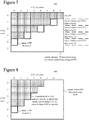
- FIGs. 5a and 5b are a block diagram of a generalized video encoder (500) in conjunction with which some described embodiments may be implemented.
- the encoder (500) receives a sequence of video pictures including a current picture as an input video signal (505) and produces encoded data in a coded video bitstream (595) as output.
- the encoder (500) is block-based and uses a block format that depends on implementation. Blocks may be further sub-divided at different stages, e.g., at the prediction, frequency transform and/or entropy encoding stages. For example, a picture can be divided into 64x64 blocks, 32x32 blocks or 16x16 blocks, which can in turn be divided into smaller blocks of sample values for coding and decoding. In implementations of encoding for the H.265/HEVC standard, the encoder partitions a picture into CTUs (CTBs), CUs (CBs), PUs (PBs) and TU (TBs).
- CTUs CTUs
- CBs CUs
- PBs PUs
- TBs TU
- the encoder (500) compresses pictures using intra-picture coding and/or inter-picture coding. Many of the components of the encoder (500) are used for both intra-picture coding and inter-picture coding. The exact operations performed by those components can vary depending on the type of information being compressed.
- a tiling module (510) optionally partitions a picture into multiple tiles of the same size or different sizes. For example, the tiling module (510) splits the picture along tile rows and tile columns that, with picture boundaries, define horizontal and vertical boundaries of tiles within the picture, where each tile is a rectangular region.
- the encoder (500) partitions a picture into one or more slices, where each slice includes one or more slice segments. Rows of certain blocks (e.g ., rows of CTUs of a slice according to the H.265/HEVC standard) can be encoded in parallel using WPP, as further explained below.
- the general encoding control (520) receives pictures for the input video signal (505) as well as feedback (not shown) from various modules of the encoder (500). Overall, the general encoding control (520) provides control signals (not shown) to other modules (such as the tiling module (510), transformer/scaler/quantizer (530), sealer/inverse transformer (535), intra-picture estimator (540), motion estimator (550) and intra/inter switch) to set and change coding parameters during encoding. In particular, the general encoding control (520) can decide whether and how to use palette prediction, intra BC prediction, intra LC prediction and intra SC prediction during encoding. The general encoding control (520) can also evaluate intermediate results during encoding, for example, performing rate-distortion analysis. The general encoding control (520) produces general control data (522) that indicates decisions made during encoding, so that a corresponding decoder can make consistent decisions. The general control data (522) is provided to the header formatter/entropy coder (590).
- a motion estimator (550) estimates the motion of blocks of sample values of a current picture of the input video signal (505) with respect to one or more reference pictures.
- the decoded picture buffer (570) buffers one or more reconstructed previously coded pictures for use as reference pictures. When multiple reference pictures are used, the multiple reference pictures can be from different temporal directions or the same temporal direction.
- the motion estimator (550) produces as side information motion data (552) such as MV data, merge mode index values, and reference picture selection data.
- the motion data (552) is provided to the header formatter/entropy coder (590) as well as the motion compensator (555).
- the motion compensator (555) applies MVs to the reconstructed reference picture(s) from the decoded picture buffer (570).
- the motion compensator (555) produces motion-compensated predictions for the current picture.
- an intra-picture estimator (540) determines how to perform intra-picture prediction for blocks of sample values of a current picture of the input video signal (505).
- the current picture can be entirely or partially coded using intra-picture coding.
- the intra-picture estimator (540) determines how to spatially predict sample values of a current block of the current picture from neighboring, previously reconstructed sample values of the current picture.
- an intra-picture estimator (540) estimates displacement from a current block, line or string to a position in the other, previously reconstructed sample values.
- a reference block, line or string of sample values in the picture is used to generate prediction values for the current block, line or string.
- the intra-picture estimator (540) estimates displacement from a current block to a reference block, which can be indicated with a BV value.
- the intra-picture estimator (540) estimates displacement from a current line (of a current block) to a reference line, which can be indicated with an offset value (indicating the displacement from the current line to the reference line).
- an intra-picture estimator estimates displacement from a current string (of a current block) to a reference string, which can be indicated with an offset value (indicating the displacement from the current string to the reference string) and a string length value.
- the intra-picture estimator can determine displacements (e.g. , for BV values in intra BC prediction or for offset values in intra SC prediction or intra LC prediction) consistent with constraints on locations of reference regions, as explained below.
- the intra-picture estimator (540) can perform offset estimation for the current block, line or string using input sample values, reconstructed sample values before in-loop filtering, or reconstructed sample values after in-loop filtering.
- the intra-picture estimator (540) can avoid a sequential-processing bottleneck (which may result from filtering reconstructed sample values of a reference block, line, string, etc. before offset estimation/intra copy prediction).
- storing the unfiltered, reconstructed sample values uses additional memory.
- the encoder can apply some in-loop filtering operations before offset estimation/intra copy prediction, and perform additional or alternative filtering in a later processing stage.
- the intra-picture estimator (540) produces as side information intra prediction data (542), such as information indicating whether intra prediction uses spatial prediction, intra BC prediction, intra LC prediction or intra SC prediction, prediction mode direction (for intra spatial prediction), BV values (for intra BC prediction), offset values (for intra LC prediction) or offset values and length values (for intra SC prediction).
- the intra prediction data (542) is provided to the header formatter/entropy coder (590) as well as the intra-picture predictor (545).
- the intra-picture predictor (545) spatially predicts sample values of a current block of the current picture from neighboring, previously reconstructed sample values of the current picture. Or, for intra copy prediction, the intra-picture predictor (545) predicts the sample values of a current block, line, string, or other section using previously reconstructed sample values of a reference block, line, string, or other section, which is indicated by a displacement (BV value, offset value, etc.) for the current block, line, string, etc. In some cases, a BV value (or other offset value) can be a predicted value.
- the BV value (or other offset value) can be different than its predicted value, in which case a differential indicates the difference between the predicted value and BV value (or other offset value).
- the intra-picture predictor (545) also uses a string length value when predicting the sample values of the current string.
- the encoder (500) represents at least some of the sample values of a CU or other unit using a palette.
- the palette represents colors used in the unit.
- the palette maps index values 0, 1, 2, ... , p to corresponding colors, which can be in RGB 4:4:4 format, BGR 4:4:4 format, GBR 4:4:4 format, YUV 4:4:4 format, or another format (color space, color sampling rate).
- An index value can represent a RGB triplet, BGR triplet or GBR triplet for a pixel, where a pixel is a set of co-located sample values.
- index values replace the sample values of pixels in the unit.
- a rare value in the unit can be encoded using an escape code value and literal values, instead of using an index value in the palette.
- the palette can change from unit to unit, and palette data specifying the palettes can be signaled in the bitstream.
- the intra/inter switch selects whether the prediction (558) for a given block will be a motion-compensated prediction or intra-picture prediction.
- no residual is calculated for a unit encoded in palette coding mode or an intra copy mode (intra BC prediction, intra LC prediction or intra SC prediction). Instead, residual coding is skipped, and the predicted sample values are used as the reconstructed sample values.
- the difference (if any) between a block of the prediction (558) and a corresponding part of the original current picture of the input video signal (505) provides values of the residual (518).
- reconstructed residual values are combined with the prediction (558) to produce an approximate or exact reconstruction (538) of the original content from the video signal (505). (In lossy compression, some information is lost from the video signal (505).)
- a frequency transformer converts spatial-domain video information into frequency-domain (i.e., spectral, transform) data.
- the frequency transformer applies a discrete cosine transform ("DCT"), an integer approximation thereof, or another type of forward block transform (e.g., a discrete sine transform or an integer approximation thereof) to blocks of prediction residual data (or sample value data if the prediction (558) is null), producing blocks of frequency transform coefficients.
- DCT discrete cosine transform
- the transformer/scaler/quantizer (530) can apply a transform with variable block sizes.
- the transformer/scaler/quantizer can determine which block sizes of transforms to use for the residual values for a current block.
- the sealer/quantizer scales and quantizes the transform coefficients.
- the quantizer applies dead-zone scalar quantization to the frequency-domain data with a quantization step size that varies on a picture-by-picture basis, tile-by-tile basis, slice-by-slice basis, block-by-block basis, frequency-specific basis or other basis.
- the quantized transform coefficient data (532) is provided to the header formatter/entropy coder (590). If the frequency transform is skipped, the sealer/quantizer can scale and quantize the blocks of prediction residual data (or sample value data if the prediction (558) is null), producing quantized values that are provided to the header formatter/entropy coder (590).
- a sealer/inverse quantizer performs inverse scaling and inverse quantization on the quantized transform coefficients.
- an inverse frequency transformer performs an inverse frequency transform, producing blocks of reconstructed prediction residual values or sample values. If the transform stage has been skipped, the inverse frequency transform is also skipped.
- the sealer/inverse quantizer can perform inverse scaling and inverse quantization on blocks of prediction residual data (or sample value data), producing reconstructed values.
- the encoder (500) When residual values have been encoded/signaled, the encoder (500) combines reconstructed residual values with values of the prediction (558) (e.g., motion-compensated prediction values, intra-picture prediction values) to form the reconstruction (538). When residual values have not been encoded/signaled, the encoder (500) uses the values of the prediction (558) as the reconstruction (538).
- the prediction e.g., motion-compensated prediction values, intra-picture prediction values
- the values of the reconstruction (538) can be fed back to the intra-picture estimator (540) and intra-picture predictor (545).
- the values of the reconstruction (538) can be used for motion-compensated prediction of subsequent pictures.
- the values of the reconstruction (538) can be further filtered.
- a filtering control (560) determines how to perform deblock filtering and SAO filtering on values of the reconstruction (538), for a given picture of the video signal (505).
- the filtering control (560) produces filter control data (562), which is provided to the header formatter/entropy coder (590) and merger/filter(s) (565).
- the encoder (500) merges content from different tiles into a reconstructed version of the picture.
- the encoder (500) selectively performs deblock filtering and SAO filtering according to the filter control data (562) and rules for filter adaptation, so as to adaptively smooth discontinuities across boundaries in the pictures.
- Other filtering such as de-ringing filtering or ALF; not shown
- Tile boundaries can be selectively filtered or not filtered at all, depending on settings of the encoder (500), and the encoder (500) may provide syntax elements within the coded bitstream to indicate whether or not such filtering was applied.
- the decoded picture buffer (570) buffers the reconstructed current picture for use in subsequent motion-compensated prediction.
- the header formatter/entropy coder (590) formats and/or entropy codes the general control data (522), quantized transform coefficient data (532), intra prediction data (542), motion data (552) and filter control data (562).
- the header formatter/entropy coder (590) can select and entropy code merge mode index values, or a default MV predictor can be used.
- the header formatter/entropy coder (590) also determines MV differentials for MV values (relative to MV predictors for the MV values), then entropy codes the MV differentials, e.g ., using context-adaptive binary arithmetic coding.
- a BV value (or other offset value) can be encoded using prediction.
- the prediction can use a default predictor (e.g ., a BV value or other offset value from one or more neighboring blocks).
- a predictor index can indicate which of the multiple predictors to use for prediction of the BV value (or other offset value).
- the header formatter/entropy coder (590) can select and entropy code predictor index values (for intra copy prediction), or a default predictor can be used.
- the header formatter/entropy coder (590) also determines differentials (relative to predictors for the BV values or other offset values), then entropy codes the differentials, e.g ., using context-adaptive binary arithmetic coding.
- the header formatter/entropy coder (590) can encode palette data.
- the header formatter/entropy coder (590) can use palette prediction as explained below.
- the header formatter/entropy coder (590) provides the encoded data in the coded video bitstream (595).
- the format of the coded video bitstream (595) can be a variation or extension of H.265/HEVC format, Windows Media Video format, VC-1 format, MPEG-x format (e.g., MPEG-1, MPEG-2, or MPEG-4), H.26x format (e.g., H.261, H.262, H.263, H.264), or another format.
- modules of an encoder (500) can be added, omitted, split into multiple modules, combined with other modules, and/or replaced with like modules.
- encoders with different modules and/or other configurations of modules perform one or more of the described techniques.
- Specific embodiments of encoders typically use a variation or supplemented version of the encoder (500).
- the relationships shown between modules within the encoder (500) indicate general flows of information in the encoder; other relationships are not shown for the sake of simplicity.
- FIG. 6 is a block diagram of a generalized decoder (600) in conjunction with which some described embodiments may be implemented.
- the decoder (600) receives encoded data in a coded video bitstream (605) and produces output including pictures for reconstructed video (695).
- the format of the coded video bitstream (605) can be a variation or extension of H.265/HEVC format, Windows Media Video format, VC-1 format, MPEG-x format ( e.g ., MPEG-1, MPEG-2, or MPEG-4), H.26x format ( e.g ., H.261, H.262, H.263, H.264), or another format.
- a picture can be organized as multiple tiles of the same size or different sizes.
- a picture can also be organized as one or more slices.
- the content of a slice or tile can be further organized as blocks or other sets of sample values.
- the decoder (600) is block-based and uses a block format that depends on implementation. Blocks may be further sub-divided at different stages. For example, a picture can be divided into 64x64 blocks, 32x32 blocks or 16x16 blocks, which can in turn be divided into smaller blocks of sample values.
- CTUs CTUs
- CBs CUs
- PBs PUs
- TBs TU
- rows of certain blocks e.g ., rows of CTUs according to the H.265/HEVC standard
- the decoder (600) decompresses pictures using intra-picture decoding and/or inter-picture decoding. Many of the components of the decoder (600) are used for both intra-picture decoding and inter-picture decoding. The exact operations performed by those components can vary depending on the type of information being decompressed.
- a buffer receives encoded data in the coded video bitstream (605) and makes the received encoded data available to the parser/entropy decoder (610).
- the parser/entropy decoder (610) entropy decodes entropy-coded data, typically applying the inverse of entropy coding performed in the encoder (500) ( e.g., context-adaptive binary arithmetic decoding).
- the parser/entropy decoder (610) produces general control data (622), quantized transform coefficient data (632), intra prediction data (642), motion data (652) and filter control data (662).
- the parser/entropy decoder (610) can entropy decode the predictor index values, e.g ., using context-adaptive binary arithmetic decoding. In some cases, the parser/entropy decoder (610) also entropy decodes differentials for BV values or other offset values ( e.g ., using context-adaptive binary arithmetic decoding), then combines the differentials with corresponding predictors to reconstruct the BV values (or other offset values).
- the parser/entropy decoder (610) can decode palette data.
- the parser/entropy decoder (610) can use palette prediction as explained below.
- the general decoding control (620) receives the general control data (622) and provides control signals (not shown) to other modules (such as the sealer/inverse transformer (635), intra-picture predictor (645), motion compensator (655) and intra/inter switch) to set and change decoding parameters during decoding.
- modules such as the sealer/inverse transformer (635), intra-picture predictor (645), motion compensator (655) and intra/inter switch
- a motion compensator receives the motion data (652), such as MV data, reference picture selection data and merge mode index values.
- the motion compensator (655) applies MVs to the reconstructed reference picture(s) from the decoded picture buffer (670).
- the motion compensator (655) produces motion-compensated predictions for inter-coded blocks of the current picture.
- the decoded picture buffer (670) stores one or more previously reconstructed pictures for use as reference pictures.
- the intra-picture predictor (645) receives the intra prediction data (642), such as information indicating whether intra-picture prediction uses spatial prediction, intra BC prediction, intra LC prediction or intra SC prediction, as well as prediction mode direction (for intra spatial prediction), BV values (for intra BC prediction), offset values (for intra LC prediction), or offset values and length values (for intra SC prediction).
- the intra prediction data (642) such as information indicating whether intra-picture prediction uses spatial prediction, intra BC prediction, intra LC prediction or intra SC prediction, as well as prediction mode direction (for intra spatial prediction), BV values (for intra BC prediction), offset values (for intra LC prediction), or offset values and length values (for intra SC prediction).
- intra prediction data such as information indicating whether intra-picture prediction uses spatial prediction, intra BC prediction, intra LC prediction or intra SC prediction, as well as prediction mode direction (for intra spatial prediction), BV values (for intra BC prediction), offset values (for intra LC prediction), or offset values and length values (for intra SC prediction).
- intra prediction data (642) such as information
- the intra-picture predictor (645) predicts the sample values of a current block, line, string, or other section using previously reconstructed sample values of a reference block, line, string, or other section, which is indicated by a displacement (BV value, offset value, etc.) for the current block, line, string, etc.
- a BV value (or other offset value) can be a predicted value.
- the BV value (or other offset value) can be different than its predicted value, in which case the BV value (or other offset value) is reconstructed using a differential and the predicted value.
- the intra-picture predictor (645) also uses a string length value when predicting the sample values of the current string.
- the decoder (600) uses a palette that represents at least some of the sample values of a CU or other unit.
- the palette maps index values to corresponding colors used in the unit.
- the palette maps index values 0, 1, 2, ... , p to corresponding colors, which can be in RGB 4:4:4 format, BGR 4:4:4 format, GBR 4:4:4 format, YUV 4:4:4 format, or another format (color space, color sampling rate).
- An index value can represent a RGB triplet, BGR triplet or GBR triplet for a pixel.
- index values from the palette are replaced with the appropriate sample values.
- An escape coded value in the unit can be decoded using an escape code value and literal values.
- the palette can change from unit to unit, based on palette data signaled in the bitstream.
- the intra/inter switch selects values of a motion-compensated prediction or intra-picture prediction for use as the prediction (658) for a given block.
- the intra/inter switch can be controlled based on a syntax element encoded for a CU of a picture that can contain intra-predicted CUs and inter-predicted CUs.
- the decoder (600) When residual values have been encoded/signaled, the decoder (600) combines the prediction (658) with reconstructed residual values to produce the reconstruction (638) of the content from the video signal.
- the decoder (600) uses the values of the prediction (658) as the reconstruction (638).
- the sealer/inverse transformer receives and processes the quantized transform coefficient data (632).
- a sealer/inverse quantizer performs inverse scaling and inverse quantization on the quantized transform coefficients.
- An inverse frequency transformer performs an inverse frequency transform, producing blocks of reconstructed prediction residual values or sample values.
- the inverse frequency transformer applies an inverse block transform to frequency transform coefficients, producing sample value data or prediction residual data.
- the inverse frequency transform can be an inverse DCT, an integer approximation thereof, or another type of inverse frequency transform (e.g ., an inverse discrete sine transform or an integer approximation thereof). If the frequency transform was skipped during encoding, the inverse frequency transform is also skipped.
- the sealer/inverse quantizer can perform inverse scaling and inverse quantization on blocks of prediction residual data (or sample value data), producing reconstructed values.
- the values of the reconstruction (638) can be fed back to the intra-picture predictor (645).
- the values of the reconstruction (638) can be further filtered.
- the decoder (600) merges content from different tiles into a reconstructed version of the picture.
- the decoder (600) selectively performs deblock filtering and SAO filtering according to the filter control data (662) and rules for filter adaptation, so as to adaptively smooth discontinuities across boundaries in the pictures.
- Other filtering (such as de-ringing filtering or ALF; not shown) can alternatively or additionally be applied.
- Tile boundaries can be selectively filtered or not filtered at all, depending on settings of the decoder (600) or a syntax element within the encoded bitstream data.
- the decoded picture buffer (670) buffers the reconstructed current picture for use in subsequent motion-compensated prediction.
- the decoder (600) can also include a post-processing filter.
- the post-processing filter (608) can include deblock filtering, de-ringing filtering, adaptive Wiener filtering, film-grain reproduction filtering, SAO filtering or another kind of filtering. Whereas "in-loop" filtering is performed on reconstructed sample values of pictures in a motion compensation loop, and hence affects sample values of reference pictures, the post-processing filter (608) is applied to reconstructed sample values outside of the motion compensation loop, before output for display.
- modules of the decoder (600) can be added, omitted, split into multiple modules, combined with other modules, and/or replaced with like modules.
- decoders with different modules and/or other configurations of modules perform one or more of the described techniques.
- Specific embodiments of decoders typically use a variation or supplemented version of the decoder (600).
- the relationships shown between modules within the decoder (600) indicate general flows of information in the decoder; other relationships are not shown for the sake of simplicity.
- This section presents examples of rules for intra-picture prediction modes when wavefront parallel processing (“WPP”) is enabled.
- WPP wavefront parallel processing
- the innovations facilitate the use of intra-picture prediction modes such as palette prediction mode, intra block copy (“BC”) mode, intra line copy (“LC”) mode and intra string copy (“SC”) mode by an encoder or decoder when WPP is enabled.
- WPP is a coding/decoding tool that facilitates parallel processing by differentially delaying the start of processing for rows of units in a picture.
- different rows of units in a picture can be encoded or decoded in parallel.
- a first row of units can be processed unit-after-unit, from left to right.
- Processing (encoding or decoding) of a second row of units need not wait for completion of processing for the entire first row of units. Instead, processing of the second row of units can begin after processing completes for several of the first row's units, which provide information used when processing the initial unit of the second row.
- processing of a third row of units can begin after processing completes for several of the second row's units.
- WPP facilitates parallel processing of different rows of units - different threads or processing cores can perform the processing for different rows of units on a staggered, time-delayed basis.
- a slice is divided into rows of CTUs.
- the first row of CTUs can be processed CTU-after-CTU.
- Processing of the second row of CTUs can begin after processing completes for the first two CTUs of the first row, which provide information (e.g ., reconstructed sample values, reconstructed MV values or BV values, context model information) used when processing the initial CTU of the second row.
- processing of the third row of CTUs can begin after processing completes for the first two CTUs of the second row.
- FIG. 7 illustrates the timing (700) of WPP for a current picture (710) according to the H.265/HEVC standard.
- the picture (710) is partitioned into CTUs, which are organized in CTU columns and CTU rows. Different CTU rows can be encoded or decoded in parallel using WPP.
- the timing of WPP reflects dependencies between CTUs during encoding or decoding.
- a given CTU may depend on information (such as reconstructed sample values, reconstructed MV values or BV values, context model information) from (1) the neighboring CTU(s) to its left, (2) the neighboring CTU(s) to its above and left, (3) the neighboring CTU(s) above the given CTU, and (4) the neighboring CTU(s) above and to the right of the given CTU, where such neighboring CTUs (1)-(4) are available ( e.g ., are within the picture, in the same slice and tile).
- Each neighboring CTU may depend on its neighboring CTUs (1)-(4), if available.
- FIG. 8 illustrates cascading dependencies for the initial CTU of a fifth CTU row.
- the initial CTU of the fifth CTU row depends on the first two CTUs of the fourth CTU row, which collectively depend on the first three CTUs of the third CTU row, and so on.
- the first CTU row (that is, CTU row 0) is processed CTU-after-CTU for wave 0.
- processing of the initial CTU in CTU row 1 can begin after encoding/decoding of the second CTU in CTU row 0 finishes.
- processing of the initial CTU in CTU row 2 can begin after encoding/decoding of the second CTU in CTU row 1 finishes.
- processing of the initial CTU in CTU row 3 can begin after encoding/decoding of the second CTU in CTU row 2 finishes
- processing of the initial CTU in CTU row 4 begins after encoding/decoding of the second CTU in CTU row 3 finishes.
- CTUs are processed from left to right in a CTU row, CTU row after CTU row from top to bottom of a picture (or slice and tile, if used).
- the context model information also called CABAC status information or entropy coding information
- used for a given CTU may account for results of processing any previous CTUs in the same CTU row and any previous CTU rows of the picture (or slice/tile), which are earlier CTUs in coding/decoding order.
- processing of the second CTU in a CTU row depends on results of processing of the first CTU in the CTU row, and so on.
- processing for the initial CTU in a CTU row depends on results of processing for the last CTU in the previous CTU row in the picture (or slice/tile).
- processing for the initial CTU in a CTU row does not depend on results of processing for the last CTU in the previous CTU row in the picture (or slice/tile).
- the processing for the initial CTU in a CTU row can start after processing finishes for the second CTU in the previous CTU row in the picture (or slice/tile), even though context model information from the last CTU in the previous CTU row is unavailable.
- Processing of the third CTU in the previous CTU row still depends on results of processing of the second CTU in that CTU row, just like when WPP is not enabled.
- an encoder When WPP is enabled, an encoder may or may not actually use WPP during encoding. Regardless, the encoder enforces constraints and prediction rules that apply when WPP is actually used. Similarly, when WPP is enabled, a decoder may or may not actually use WPP during decoding.
- a syntax element in a bitstream can indicate whether WPP is enabled for a video sequence, set of pictures or picture. For example, the syntax element can be signaled in a SPS, PPS or other syntax structure in the bitstream.
- the value of the syntax element entropy_coding_sync_enabled_flag indicates whether WPP is enabled for the picture(s) associated with the PPS syntax structure. If entropy_coding_sync_enabled_flag equals 1, WPP is enabled for the picture(s). Otherwise, WPP is not enabled for the picture(s).
- a palette coding/decoding mode uses a palette to represent at least some of the sample values of a unit (e.g., a CU in H.265/HEVC implementations or other unit).
- the palette maps index values 0, 1, 2, ... , p to corresponding colors, which can be in RGB 4:4:4 format, BGR 4:4:4 format, GBR 4:4:4 format, YUV 4:4:4 format, or another format (color space, color sampling rate).
- An index value can represent a RGB triplet, BGR triplet or GBR triplet for a pixel.
- FIG. 9 shows two examples of palettes.
- the palette for a current unit (that is, the "current palette”) includes p index values 0, ...,p -1, which are associated with RGB triplets.
- the palette for a previous unit (represented in the "previous palette data") includes q index values 0, ..., q-1, which are associated with RGB triplets.
- the values of p and q can be the same or different.
- an encoder can replace the sample values of a pixel using an index value, which may be further encoded, e.g ., using entropy coding.
- a decoder can restore the sample values of the pixel from the index value using the palette, e.g., after entropy decoding of the index value.
- palette coding/decoding mode can be effective when a unit includes relatively few distinct colors, which is a common characteristic for screen content video.
- a rare color in a unit can be encoded using an escape code value and literal values (for the respective sample values), instead of including the rare color directly in the palette.
- palettes typically change from unit to unit within the picture.
- an encoder signals palette data, which may be entropy coded, in a bitstream.
- a decoder receives and parses the palette data, entropy decodes it as appropriate, and reconstructs the palettes.
- the encoder and decoder can use palette prediction to reduce the bit rate associated with signaling palette data.
- palette prediction can be any approach used during encoding or decoding to predict the values of the palette for a current unit (current palette) using palette data from one or more palettes for previous units (previous palette data).
- current palette current palette
- previous palette data previous palette data
- colors typically change from unit to unit within a picture, in many cases at least some of the colors in a given unit are also used in an adjacent unit.
- Palette prediction exploits that observation to reduce the bit rate for palette data.
- FIG. 9 shows a simplified example (900) of palette prediction in which the palette for a current unit (current palette) is predicted using the palette for a previous unit (represented in the previous palette data).
- the previous palette data can be from the palette used by the previous unit encoded or decoded before the current unit, if the previous unit used palette coding/decoding mode. If the previous unit did not use palette coding/decoding mode, the previous palette data for the current unit can be "inherited" from the previous unit. That is, the previous palette data that was available to the previous unit can be reused as the previous palette data available to the current unit.
- previous palette data is, in effect, status or state information for the current unit.
- the previous palette data for the current unit can include palette data from the palette of the most recent, previously processed unit (if any) that used palette coding/decoding mode.
- the encoder can determine whether the current palette is the same as the previous palette data. If so, the encoder can simply indicate the previous palette data is to be reused as the current palette. Otherwise (current palette is different than the previous palette data), the encoder determines changes between the previous palette data and the current palette, and signals syntax elements that indicate the changes. For example, as shown in FIG. 9 , for a given index value of the current palette, the encoder signals whether the corresponding color for the given index value is a color in the previous palette data ("prev") or a new color (“new"). If the corresponding color is a color in the previous palette data, the encoder signals the index value (from the previous palette data) for the color in the previous palette data, which can be used to populate the current palette. In FIG.
- the color for index value 1 of the previous palette data is re-assigned to index value 0 in the current palette
- the color for index value 0 of the previous palette data is re-assigned to index value 2 in the current palette.
- colors can change positions from palette to palette, e.g., so that the most common colors have the lowest index values, which may improve the efficiency of entropy coding.
- the encoder If the corresponding color for a given index value is a new color, the encoder signals the triplet for the new color. In FIG. 9 , for example, for index value 1 in the current palette, the encoder signals a new triplet (215, 170, 200), which is used to update the current palette.
- the decoder can determine whether the current palette is the same as the previous palette data, which is available at the decoder. If so, the decoder can reuse the previous palette data as the current palette. Otherwise (current palette is different than the previous palette data), the decoder receives and parses syntax elements that indicate the changes between the previous palette data and the current palette. For example, as shown in FIG. 9 , for a given index value of the current palette, the decoder determines whether the corresponding color for the given index value is a color in the previous palette data ("prev") or a new color ("new").
- the decoder receives and parses a syntax element that indicates the index value (from the previous palette data) for the color in the previous palette data, which can be used to populate the current palette. If the corresponding color for a given index value is a new color, the decoder receives and parses syntax elements that indicate the new color.
- the encoder and decoder After constructing the current palette, the encoder and decoder update the previous palette data for the next unit to store palette data from the current palette. This new "previous palette data" can be used to predict the palette for the next unit.
- FIG. 9 shows a simplified example (900).
- the syntax elements and rules used to signal palette data can be more complicated.
- another approach is used to signal palette data.
- previous palette data for purposes of palette prediction is used to predict the palette of a current unit (current palette).
- the previous palette data can be actual palette data from the neighbor unit encoded or decoded before the current unit (if the neighbor unit used palette coding/decoding mode). Or (if the neighbor unit did not use palette coding/decoding mode), the previous palette data available to the neighbor unit can be reused (or "inherited") as the previous palette data for the current unit.
- the previous palette data is from the last unit in the previous row (e.g ., from the palette of the last unit if the last unit used palette coding/decoding mode; otherwise, the previous palette data available to the last unit).
- previous palette data from the last unit in the previous row might not be available. Resetting palette prediction at the start of each row of units (no predictor for palette prediction for the initial unit in the current unit), however, can have a negative impact on coding efficiency.
- the encoder or decoder can use previous palette data from one of the first two units in the previous row (e.g ., one of the first two CUs in the first two CTUs of the previous row), which have already been processed in order for processing of the initial unit in the current row to start.
- the previous palette data for purposes of palette prediction is from the second unit of the previous row (actual palette data of the second unit if the second unit used palette coding/decoding mode, or the previous palette data available to the second unit of the previous row otherwise).
- the previous palette data is potentially palette data from the first unit in the previous row (if the first unit used palette coding/decoding mode) or (if neither of the first two units in the previous row used palette coding/decoding mode) the previous palette data from the first unit of the previous row, which may depend on a palette for the second unit of the row before the previous row, and so on.
- the previous palette data for purposes of palette prediction is palette data from the neighbor unit encoded or decoded before the current unit (if the neighbor unit used palette coding/decoding mode) or (if the neighbor unit did not use palette coding/decoding mode) the previous palette data available to the neighbor unit, just like when WPP is not enabled.
- FIG. 10 shows palette prediction dependencies (1000) for a current picture (1010) processed with WPP enabled according to some example implementations.
- the picture (1010) is organized by CTU rows and CTU columns.
- each CTU includes a single CU. More generally, a given CTU can be recursively split into multiple CUs (e.g., a single CU can be split into four CUs, each of which may be further split into smaller CUs).
- the state of processing e.g ., the current CTUs being encoded or decoded
- the state of processing generally corresponds to the state of processing shown in FIG. 7 .
- the arrows in FIG. 10 show the direction of palette prediction when WPP is enabled.
- the previous palette data is from the CU to the left.
- the previous palette data is from the second CU of the previous row.
- the previous palette data is from the previous CU in the same row.
- any CU that uses palette coding/decoding mode its palette is used to construct the previous palette data for prediction of the palette of the next CU. If a given CU does not use palette coding/decoding mode, the previous palette data that was available to the given CU is retained as the previous palette data of the next CU.
- the previous CU can be the earlier CU in z-scan order.
- the earlier CU can be in the same CTU or a different CTU (for the first CU of the CTU).
- Section VII.D explains, with reference to FIG. 17 , examples of z-scan order in some example implementations.
- the encoder and decoder can use memory to store previous palette data used for palette prediction.
- the amount of palette data that is saved for the previous palette data depends on implementation.
- the previous palette data can include a count C of colors in the previous palette data and details of sample values (e.g ., color triplets in RGB 4:4:4 format, GBR 4:4:4 format, BGR 4:4:4 format, YUV 4:4:4 format, or another format) for the colors.
- the encoder and decoder can save all palette data for a previous palette. Saving all palette data for the previous palette, however, can consume a significant amount of memory for a large palette.
- the encoder and decoder limit C by a threshold count, where the threshold count depends on implementation.
- the encoder and decoder save previous palette data for the first C different colors in the previous palette, where C is limited by a threshold count.
- the threshold count is 16 or 32.
- the encoder and decoder save previous palette data for, at most, the first C 1 different colors.
- the encoder and decoder save previous palette data for, at most, the first C 2 different colors for palette prediction within a current row.
- C 1 is 16 or 32
- C 2 is 64.
- FIG. 11 shows a generalized technique (1100) for encoding that includes palette prediction, when WPP is enabled.
- An encoder such as the encoder shown in FIG. 3 or FIGs. 5a and 5b , or other encoder, can perform the technique (1100).
- FIG. 12 shows a generalized technique (1200) for decoding that includes palette prediction, when WPP is enabled.
- a decoder such as the decoder shown in FIG. 4 or FIG. 6 , or other decoder, can perform the technique (1200).
- an encoder encodes (1110) a picture with WPP enabled.
- the encoding (1110) produces encoded data.
- the encoder predicts a palette for an initial unit in a current WPP row of the picture using previous palette data from a previous unit in a previous WPP row of the picture.
- the encoder outputs (1120) the encoded data as part of a bitstream.
- a decoder receives (1210) encoded data as part of a bitstream.
- the decoder decodes (1220) the encoded data with WPP enabled.
- the decoding (1220) reconstructs a picture.
- the decoder predicts a palette for an initial unit in a current WPP row of the picture using previous palette data from a previous unit in a previous WPP row of the picture.
- the current WPP row and the previous WPP row are rows of CTUs, and the initial unit and previous unit are CUs.
- WPP rows are rows of another type of unit and/or the initial and previous units are another type of unit.
- a syntax element in the bitstream can indicate whether WPP is enabled for a video sequence, set of pictures or picture.
- the syntax element can be signaled in a SPS syntax structure, PPS syntax structure (e.g ., the syntax element entropy_coding_sync_enabled_flag in H.265/HEVC implementations) or other syntax structure in the bitstream.
- the palette for the initial unit in the current WPP row represents at least some colors used in the initial unit in the current WPP row.
- the previous palette data from the previous unit in the previous WPP row may represent at least some colors used in a palette for the previous unit in the previous WPP row (if the previous unit used palette coding/decoding mode). Or (if the previous unit did not use palette coding/decoding mode), the previous palette data from the previous unit in the previous WPP row may have been inherited by the previous unit from an earlier unit, which may have used palette coding/decoding mode or itself inherited the previous palette data. Colors not represented in a palette can be escape coded.
- the previous WPP row can be the WPP row immediately above the current WPP row.
- the previous unit in the previous WPP row can be above the initial unit in the current WPP row (e.g., the first unit in the previous row in FIG. 10 ), or it can be above and to the right of the initial unit in the current WPP row ( e.g ., the second unit in the previous row in FIG. 10 ).
- the encoder or decoder can predict the palette (of the subsequent unit) using palette data from the palette for the initial unit in the current WPP row.
- palette prediction can include several stages. For example, during encoding, the encoder can determine (based on a comparison of the current palette to the previous palette data) whether to reuse the previous palette data from the previous unit in the previous WPP row as the palette for the initial unit in the current WPP row (current palette). During decoding, the decoder can determine (based on information signaled by the encoder) whether to reuse the previous palette data from the previous unit in the previous WPP row as the palette for the initial unit in the current WPP row (current palette).
- the encoder can select one or more colors from the previous palette data from the previous unit in the previous WPP row to include in the palette for the initial unit in the current WPP row (current palette).
- the encoder signals syntax elements indicating the selected colors.
- the decoder can receive and parse the syntax elements and, based on the syntax elements, select one or more colors from the previous palette data from the previous unit in the previous WPP row to include in the palette for the initial unit in the current WPP row (current palette).
- the encoder and decoder can use another approach to signal palette data.
- the encoder and decoder can store all previous palette data from the previous unit in the previous WPP row. For example, the encoder and decoder can save, for each of C colors in the previous palette data from the previous unit in the previous WPP row, one or more color component values. Alternatively, to reduce memory consumption in some cases, the encoder and decoder can limit C by a threshold count for the previous palette data, such that palette data for the first C colors, limited by the threshold count, is stored for palette prediction.
- an intra copy mode uses intra copy prediction in which a current block, line, string or other section in a picture is predicted using previously reconstructed sample values in a reference block, line, string or other section in the same picture.
- the intra copy mode can use intra block copy ("BC") prediction, intra line copy (“LC”) prediction, or intra string copy (“SC”) prediction.
- BC intra block copy
- LC intra line copy
- SC intra string copy
- an intra BC mode uses intra BC prediction in which the sample values of a current block of a picture are predicted using sample values in the same picture.
- a block vector (“BV") value indicates a displacement from the current block to a block of the picture (the "reference block") that includes the sample values used for prediction.
- the reference block provides predicted values for the current block.
- the sample values used for prediction are previously reconstructed sample values, which are thus available at the encoder during encoding and at the decoder during decoding.
- the BV value is signaled in the bitstream, and a decoder can use the BV value to determine the reference block of the picture to use for prediction.
- FIG. 13 shows an example (1300) of intra BC prediction for a current block (1330) of a current picture (1310).
- the current block can be a coding block ("CB") of a coding unit ("CU"), prediction block ("PB") of a prediction unit ("PU"), transform block ("TB") of a transform unit (“TU”) or other block.
- the size of the current block can be 64x64, 32x32, 16x16, 8x8 or some other size.
- Blocks can be symmetrically or asymmetrically partitioned into smaller blocks for purposes of intra BC prediction. More generally, the size of the current block is m x n, where each of m and n is a whole number, and where m and n can be equal to each other or can have different values.
- the current block can be square or rectangular. Alternatively, the current block can have some other shape.
- the BV (1340) indicates a displacement (or offset) from the current block (1330) to a reference block (1350) of the picture that includes the sample values used for prediction.
- the reference block (1350) can be identical to the current block (1330), or it can be an approximation of the current block (1330).
- the top-left position of a current block is at position ( x 0 , y 0 ) in the current picture, and suppose the top-left position of the reference block is at position ( x 1 , y 1 ) in the current picture.
- the BV indicates the displacement ( x 1 - x 0 , y 1 - y 0 ).
- the BV value is (-130, -24).
- a negative horizontal displacement indicates a position to the left of the current block
- a negative vertical displacement indicates a position above the current block.
- Intra BC prediction can improve coding efficiency by exploiting redundancy (such as repeated patterns inside a picture) using BC operations. Finding a matching reference block for a current block can be computationally complex and time consuming, however, considering the number of candidate reference blocks that the encoder may evaluate.
- FIG. 14 shows an example (1400) illustrating some of the candidate reference blocks for a current block (1430) of a current picture (1410) when WPP is not enabled.
- Four BVs (1441, 1442, 1443, 1444) indicate displacements for four candidate reference blocks.
- the candidate reference blocks can be anywhere within the reconstructed content of the current picture (1410).
- a candidate reference block can overlap with other candidate reference blocks, as shown for the candidate reference blocks indicated by the BVs (1443, 1444).
- a reference block is constrained to be within the same slice and tile as the current block. Such intra BC prediction does not use sample values in other slices or tiles.
- the location of a reference block may be subject to one or more other constraints, e.g., a constraint when WPP is enabled, as described below.
- a block with prediction mode of intra BC prediction can be a CB, PB or other block.
- the BV for the block can be signaled at CU level (and other CBs in the CU use the same BV or a scaled version thereof).
- the BV for the block can be signaled at PU level (and other PBs in the PU use the same BV or a scaled version thereof).
- the BV for an intra-BC prediction block is signaled at an appropriate syntax level for the block.
- an intra LC mode uses intra LC prediction in which the sample values of a current line of a current block of a picture are predicted using sample values in the same picture.
- An offset value indicates a displacement from the current line to a line of the picture (the "reference line") that includes the sample values used for prediction.
- the offset value is signaled in the bitstream, and a decoder can use the offset value to determine the reference line to use for prediction.
- FIG. 15 illustrates an example (1500) of intra LC prediction for lines of a current block (1530) of a current picture.
- the current block can be a CB of a CU, PB of a PU, TB of a TU or other block.
- the size of the current block can be 64x64, 32x32, 16x16, 8x8 or some other size. More generally, the size of the current block is m x n , where each of m and n is a whole number, and where m and n can be equal to each other or can have different values.
- the current block can be square or rectangular.
- a block is split into horizontal lines or vertical lines. Horizontal lines have a height of 1 sample and have the width of the current block. Vertical lines have a width of 1 sample and have the height of the current block.
- a first offset (1551) indicates a displacement from a first line (1541) of the current block (1530) to a reference line (1561) that includes the sample values used for prediction of the first line (1541).
- a reference line can be identical to a given line, or it can be an approximation of the given line.
- a second offset (1552) indicates a displacement from a second line (1542) of the current block (1530) to a reference line (1562) that includes the sample values used for prediction of the second line (1542).
- An offset value (1551, 1552) is similar to a BV value, in that it indicates a displacement within the current picture.
- FIG. 15 shows horizontal lines, the current block (1530) can instead be split into vertical lines for intra LC prediction.
- a syntax element per block, per unit or per picture can indicate whether horizontal or vertical lines are used for intra LC prediction.
- Intra LC prediction can improve coding efficiency by exploiting redundancy (such as repeated patterns inside a picture) using LC operations.
- the candidate reference lines can be anywhere within the reconstructed content of the current picture.
- a candidate reference line can overlap with other candidate reference lines.
- a reference line is constrained to be within the same slice and tile as the current line.
- the location of a reference line may be subject to one or more other constraints, e.g ., a constraint when WPP is enabled, as described below.
- an intra SC mode uses intra SC prediction in which the sample values of a current string of a current block of a picture are predicted using sample values in the same picture.
- An offset value indicates a displacement from the current string to a string of the picture (the "reference string”) that includes the sample values used for prediction.
- a string length value indicates the length of the string in terms of sample values. The offset value and string length value are signaled in the bitstream, and a decoder can use the offset value and string length value to determine the reference string to use for prediction.
- FIG. 16 shows an example (1600) of intra SC prediction for strings of a current block (1630) of a current picture.
- the current block can be a CB of a CU, PB of a PU, TB of a TU or other block.
- the size of the current block can be 64x64, 32x32, 16x16, 8x8 or some other size. More generally, the size of the current block is m x n , where each of m and n is a whole number, and where m and n can be equal to each other or can have different values. Thus, the current block can be square or rectangular.
- a block is split into one or more strings. In FIG. 16 , the current block (1630) is split into three strings.
- the strings of a block can be scanned horizontally - from left to right in a given row, then the next row, and so on. Or, the strings of a block can be scanned vertically - from top to bottom in a given column, then the next column, and so on.
- the strings in FIG. 16 are horizontally scanned.
- a first offset (1651) indicates a displacement from a first string (1641) of the current block (1630) to a reference string (1661) that includes the sample values used for prediction of the first string (1641).
- the length of each of the first string (1641) and corresponding reference string (1661) is 6 sample values.
- a reference string can be identical to a given string, or it can be an approximation of the given string.
- a second offset (1652) indicates a displacement from a second string (1642) of the current block (1630) to a reference string (1662) that includes the sample values used for prediction of the second string (1642).
- the length of each of the second string (1642) and corresponding reference string (1662) is 14 sample values.
- an offset value (1651, 1652) indicates a displacement within the current picture.
- FIG. 16 shows horizontal scanning, the current block (1630) can instead be split into strings that are scanned vertically for intra SC prediction.
- a syntax element per block, per unit or per picture can indicate whether horizontal or vertical scanning order is used for intra SC prediction.
- Intra SC prediction can improve coding efficiency by exploiting redundancy (such as repeated patterns inside a picture) using SC operations.
- Intra SC prediction is more flexible than intra BC prediction or intra LC prediction (allowing partitioning into arbitrary strings, not just fixed partitions), but signals more information (string length values in addition to offset values).
- the candidate reference strings can be anywhere within the reconstructed content of the current picture.
- a candidate reference string can overlap with other candidate reference strings.
- a reference string is constrained to be within the same slice and tile as the current string. The location of a reference string may be subject to one or more other constraints, e.g ., a constraint when WPP is enabled, as described below.
- Intra copy prediction operations for intra BC mode, intra LC mode or intra SC mode can be applied at the level of CB (when a BV value or other offset value is signaled per CB or part thereof) or PB (when a BV value or other offset is signaled per PB or part thereof).
- a reference region is constrained to not overlap the current region or block including the current region.
- intra copy prediction operations can be applied for smaller sections within a PB or CB, even when the BV value or other offset value is signaled for the PB or CB (or part thereof). For example, for a first section of a block, the reference region includes positions outside the block.
- the reference region used in intra copy prediction operations can include positions in the previously reconstructed first section of the same block.
- a BV value or offset value can reference positions in the same PB or CB. Allowing intra copy prediction operations to be applied for sections within a PB or CB facilitates use of BV values or other offsets with relatively small magnitudes.
- an encoder can check the validity of the BV value or other offset value by considering the z-scan orders of the current region and the reference region (which are in the same slice and same tile). For example, the encoder checks that the z-scan order of the block containing the reference region's bottom-right position ( x 0 + offset x + m -1 , y 0 + offset y + n -1) is smaller than the z -scan order of the block containing the current region's top-left position ( x 0 , y 0 ), where offset indicates the offset value and the current region and reference region have dimensions m x n .
- the encoder can also check that the offset value satisfies at least one of the conditions offset x + m ⁇ 0 and offset y + n ⁇ 0, ensuring that the reference region does not overlap the current region.
- the z-scan order follows a sequentially specified ordering of units that partition a picture.
- FIG. 17 shows example z-scan order (1700) for a current region (1730) and units that might include the bottom-right position of a reference region.
- the current region (1730) can be a CB, PB or other block, a line, or a rectangle that includes a string.
- the z-scan orders are generally assigned to units sequentially from left-to-right in a row, repeating in successive rows from top-to-bottom. When a unit is split, z-scan orders are assigned within the split unit, recursively.
- the z-scan order proceeds CTU-to-CTU along a CTU raster scan pattern (left-to-right in a CTU row, repeating in successive CTU rows from top-to-bottom). If a CTU is split, the z-scan order follows a raster scan pattern for CUs of a quadtree within the split CTU. And, if a CU is split ( e.g., into multiple CUs, or into multiple PUs), the z-scan order follows a raster scan pattern for blocks within the split CU.
- a BV value or other offset value is signaled for a CU, PU or other unit, and is applied for all blocks of the unit.
- the BV value or other offset value can be used for all blocks without scaling, or it can be scaled for blocks in different color components.
- different BV values or other offset values can be signaled for the different blocks of a unit.
- the same prediction mode e.g ., intra BC mode
- different blocks can have different prediction modes.
- intra BC prediction, intra LC prediction and intra SC prediction use previously reconstructed sample values in a picture to predict the sample values of a current block, line or string of the same picture.
- the area of a picture that includes the previously reconstructed sample values when WPP is enabled is different than the area of the picture that includes the previously reconstructed sample values when WPP is not enabled.
- some constraints on location of a reference region are enforced whether or not WPP is enabled.
- One or more other constraints on the location of the reference region apply when WPP is enabled.
- the constraints on the location of the reference region can take the form of limits on allowed BV values for intra BC prediction or limits on allowed offset values for intra LC prediction or intra SC prediction.
- FIG. 18 shows an example (1800) of constraints on location of a reference region for a current region (1830) of a picture (1810) when WPP is enabled according to some example implementations.
- the picture (1810) is organized by CTU rows and CTU columns.
- the current region (1830) is encoded or decoding with an intra copy mode.
- the current region (1830) is part of a current CTU.
- dependencies cascade from previous CTU rows.
- WPP is enabled, for processing of the current CTU to start, the CTU(s) to its left in the same row have been processed, and the CTUs in the previous row up to the above-right CTU have been processed.
- the CTUs to the left in the same row and CTUs in the previous row up to the above-right CTU have been processed.
- these previously processed CTUs provide the reconstructed content guaranteed to be available for intra copy prediction when WPP is enabled.
- FIG. 18 shows some of the candidate reference regions for the current region (1830) of the current picture (1810).
- Four offset values (1841, 1842, 1843, 1844) indicate displacements for four candidate reference regions.
- a candidate reference region can overlap with other candidate reference regions.
- the candidate reference regions can be anywhere within the reconstructed content of the current picture (1810).
- WPP is not enabled
- the reconstructed content of the current picture (1810) generally includes CTUs to the left of the current CTU and all CTUs in previous CTU rows.
- WPP is enabled, however, less reconstructed content is available, as shown in FIG. 18 .
- three of the offset values (1841, 1842, 1843) indicate valid reference regions.
- These valid reference regions include only sample values within the reconstructed content guaranteed to be available for intra copy prediction when WPP is enabled.
- One of the offset values (1844) indicates an invalid reference region, which includes at least some sample values outside the reconstructed content guaranteed to be available for intra copy prediction when WPP is enabled.
- FIG. 19 shows a generalized technique (1900) for encoding with rules enforced for intra copy mode when WPP is enabled.
- An encoder such as the encoder shown in FIG. 3 or FIGs. 5a and 5b , or other encoder, can perform the technique (1900).
- FIG. 20 shows a generalized technique (2000) for decoding with rules enforced for intra copy mode when WPP is enabled.
- a decoder such as the decoder shown in FIG. 4 or FIG. 6 , or other decoder, can perform the technique (2000).
- an encoder encodes (1910) a picture with WPP enabled.
- the encoding (1910) produces encoded data.
- an intra copy mode e.g., a mode using intra BC prediction, intra LC prediction or intra SC prediction
- the encoder enforces one or more constraints attributable to the WPP.
- the encoder outputs (1920) the encoded data as part of a bitstream.
- a decoder receives (2010) encoded data as part of a bitstream.
- the encoded data satisfies, for an intra copy mode (e.g., a mode using intra BC prediction, intra LC prediction or intra SC prediction), one or more constraints attributable to WPP.
- the decoder decodes (2020) the encoded data with the WPP enabled.
- the decoding (2020) reconstructs a picture.
- a syntax element in the bitstream can indicate whether WPP is enabled for a video sequence, set of pictures or picture.
- the syntax element can be signaled in a SPS syntax structure, PPS syntax structure (e.g ., the syntax element entropy_coding_sync_enabled_flag in H.265/HEVC implementations) or other syntax structure in the bitstream.
- the intra copy mode can be intra BC mode.
- an offset value indicates a displacement to a reference block in the picture.
- the reference block includes previously reconstructed sample values.
- the intra copy mode can be intra LC mode.
- an offset value indicates a displacement to a reference line in the picture.
- the reference line includes previously reconstructed sample values that are scanned in a line scanning direction, which can be horizontal or vertical.
- the intra copy mode can be intra SC mode. In this case, for a current string in a block of the picture, an offset value indicates a displacement to a reference string in the picture.
- the reference string includes previously reconstructed sample values that are scanned in a string scanning order, which can be horizontal or vertical.
- a length value indicates length for each of the current string and the reference string.
- the intra copy mode can be some other mode that uses an offset value to find a reference block, line, string or other section in a picture, for a current block, line, string or other section in the same picture, where the reference block, line, string, etc. includes previously reconstructed sample values.
- the constraint(s) attributable to WPP can include a constraint that a horizontal displacement value from a reference region to a current region is less than or equal to a vertical displacement value from the current region to the reference region.
- the horizontal displacement value measures a difference from a WPP column that includes a right edge of the reference region to a WPP column that includes a left edge of the current region
- the vertical displacement value measures a difference from a WPP row that includes a top edge of the current region to a WPP row that includes a bottom edge of the reference region.
- each of the WPP columns is a column of CTUs
- each of the WPP rows is a row of CTUs.
- the constraint(s) attributable to WPP include one or more other and/or additional constraints.
- the intra copy mode is intra BC mode
- the current region is a current block
- the reference region is a reference block.
- the intra copy mode is intra LC mode
- the current region is a current line
- the reference region is a reference line.
- the intra copy mode is intra SC mode
- the current region is a rectangle that includes a current string
- the reference region is a rectangle that includes a reference string.
- the encoder or decoder can identify the rectangle that includes the current string by determining a rectangle that includes a start position of the current string, an end position of the current string, and any positions between the start position and the end position of the current string in a string scanning order ( e.g ., horizontal, vertical).
- the encoder or decoder can identify the rectangle that includes the reference string using an offset value applied to the rectangle that includes the current string.
- the encoder can also enforce one or more other constraints that are not attributable to WPP. For example, the encoder can check that a top-left position of the current region and a top-left position of the reference region are in the same slice, if applicable, and in the same tile, if applicable. As another example, the encoder can check that the top-left position of the current region and a bottom-right position of the reference region are in the same slice, if applicable, and in the same tile, if applicable.
- the encoder can check that one of the following three conditions is satisfied: (a) a CTU row that includes a bottom edge of the reference region is above a CTU row that includes a top edge of the current region; (b) if the CTU row that includes the bottom edge of the reference region equals the CTU row that includes the top edge of the current region, then a CTU column that includes the right edge of the reference region is left of a CTU column that includes a left edge of the current region; and (c) if the CTU row that includes the bottom edge of the reference region equals the CTU row that includes the top edge of the current region, and if the CTU column that includes the right edge of the reference region equals the CTU column that includes the left edge of the current region, then the bottom-right position of the reference region is earlier in z-scan order than the top-left position of the current region.
- constraints that the encoder can enforce for intra BC prediction when WPP is enabled.
- the constraints verify that a candidate reference block indicated by a BV value includes reconstructed sample values that will be available when the current block is encoded or decoded, even when WPP is enabled.
- the current block starts from position ( x 0 , y 0 ), relative to the top-left position of the current picture.
- the width and height of the current block are w block and h block , respectively.
- the current block is part of a current CU.
- the CTU size is S.
- the current CU starts from ( x CU , y CU ) relative to the top-left position of the picture.
- the block vector is ( BV x , BV y ).
- the encoder verifies that all of the following constraints are satisfied.
- the encoder verifies that the position ( x 0 , y 0 ) and the position ( x 0 + BV x , y 0 + BV y ) are in the same slice and in the same tile. That is, the encoder verifies that the top-left position of the current block and the top-left position of the reference block are in the same slice and in the same tile. If the two positions are in different slices or different tiles, the first constraint is not satisfied.
- the encoder verifies that the position ( x 0 , y 0 ) and the position ( x 0 + BV x + w block -1, y 0 + BV y + h block -1) are in the same slice and same tile. That is, the encoder verifies that the top-left position of the current block and the bottom-right position of the reference block are in the same slice and in the same tile. If the two positions are in different slices or different tiles, the second constraint is not satisfied.
- the encoder checks the first and second constraints whether or not WPP is enabled.
- the encoder verifies that one of the following three conditions is satisfied.
- the encoder checks the third constraint whether or not WPP is enabled.
- the encoder checks whether ( y 0 + BV y + h block - 1 )/ S ⁇ y 0 / S. That is, the encoder calculates the CTU row that includes the bottom edge of the reference block: ( y 0 + BV y + h block -1)/ S. The encoder also calculates the CTU row that includes the top edge of the current block: y 0 / S. The encoder then checks whether the CTU row that includes the bottom edge of the reference block is above the CTU row that includes the top edge of the current block. If so, the reference block necessarily includes previously reconstructed sample values, at least when WPP is not enabled.
- the encoder checks whether the bottom-right position of the reference block is earlier in z-scan order than the top-left position of the current block. The third condition applies if prediction from within the current CU is allowed. If prediction from within the current CU is not allowed, ( x 0 , y 0 ) should be ( x CU , y CU ).
- the encoder checks the fourth constraint when WPP is enabled. For the fourth constraint, the encoder verifies that ( x 0 + BV x + w block -1)/ S - x 0 / S ⁇ y 0 / S - ( y 0 + BV y + h block -1)/ S. That is, the encoder calculates the difference between the CTU column that includes the right edge of the reference block and the CTU column that includes the left edge of the current block: ( x 0 + BV x + w block -1)/ S - x 0 / S.
- the encoder also calculates the difference between the CTU row that includes the top edge of the current block and the CTU row that includes the bottom edge of the reference block: y 0 / S - ( y 0 + BV y + h block -1)/ S.
- the encoder verifies that the first difference (between CTU columns) is less than or equal to the second difference (between CTU rows). As shown in the jagged line of CTUs from the current CTU upward and to the right in FIG. 8 or FIG. 18 , this verifies that the reference block is part of reconstructed content guaranteed to be available for prediction when WPP is enabled.
- constraints that the encoder can enforce for intra LC prediction when WPP is enabled.
- the constraints verify that a candidate reference line indicated by an offset value includes reconstructed sample values that will be available when the current line is encoded or decoded, even when WPP is enabled.
- the current block starts from position ( x 0 , y 0 ), relative to the top-left position of the current picture.
- the width and height of the current block are w block and h block , respectively.
- the current block is part of a current CU.
- the CTU size is S.
- the offset value for the current line is ( offset x , offset y ). L lines of the current block have already been processed.
- the encoder defines start and end positions of the current line of the current block.
- the position ( x curr_line_start , y curr_line_start ) is the start position of the current line, and ( x curr_line_end , y curr_line_end ) is the end position of the current line.
- horizontal scanning also called row mode
- every line is a row of the current block:
- ( x curr_line_start , y curr_line_start ) ( x 0 , y 0 +L)
- ( x curr_line_end , y curr_line_end ) ( x 0 + w block -1 , y 0 + L ) .
- the encoder also defines start and end positions of a candidate reference line, which predicts the current line.
- the position ( x ref_line_start , y ref_line_start ) is the start position of the reference line.
- the position ( x ref_line_end , y ref_line_end ) is the end position of the reference line.
- a reference line can be a row (when horizontal scanning is used) or column (when vertical scanning is used).
- the encoder verifies that all of the following constraints are satisfied. For some of these constraints, the top-left position ( x 0 , y 0 ) of the current block is considered. For such constraints, alternatively, the start position ( x curr_line_start , y curr_line_start ) of the current line can be checked instead of the top-left position ( x 0 , y 0 ) of the current block.
- the encoder verifies that the position ( x 0 , y 0 ) and the position ( x refline_start , y ref_line_start ) are in the same slice and in the same tile. That is, the encoder verifies that the top-left position of the current block and the start position of the reference line are in the same slice and in the same tile. If the two positions are in different slices or different tiles, the first constraint is not satisfied.
- the encoder verifies that the position ( x 0 , y 0 ) and the position ( x ref_line_end , y ref_line_end ) are in the same slice and same tile. That is, the encoder verifies that the top-left position of the current block and the end position of the reference line are in the same slice and in the same tile. If the two positions are in different slices or different tiles, the second constraint is not satisfied.
- the encoder checks the first and second constraints whether or not WPP is enabled.
- the encoder verifies that one of the following three conditions is satisfied.
- the encoder checks the third constraint whether or not WPP is enabled.
- the encoder checks whether ( y ref_line_end / S ⁇ y 0 / S. That is, the encoder calculates the CTU row that includes the bottom edge or position of the reference line: y ref_line_end / S . The encoder also calculates the CTU row that includes the top edge of the current block: y 0 / S. The encoder then checks whether the CTU row that includes the bottom edge or position of the reference line is above the CTU row that includes the top edge of the current block. If so, the reference line necessarily includes previously reconstructed sample values, at least when WPP is not enabled.
- the encoder checks whether x ref_line_end / S ⁇ x 0 / S. That is, if the CTU row that includes the bottom edge or position of the reference line equals the CTU row that includes the top edge of the current block (same CTU row), the encoder calculates (a) the CTU column that that includes the right edge or position of the reference line ( x ref_line_end / S ), and (b) the CTU column that includes the left edge of the current block ( x 0 / S ). The encoder then checks whether the CTU column that includes the right edge or position of the reference line is left of a CTU column that includes the left edge of the current block. If so, the reference line necessarily includes previously reconstructed sample values.
- the encoder checks whether the end position of the reference line is earlier in z-scan order than the start position of the current line. The third condition applies if prediction from within the current CU is allowed. If prediction from within the current CU is not allowed, ( x curr_line_start , y curr_line_star ) should be ( x 0 , y 0 ).
- the encoder checks the fourth constraint when WPP is enabled. For the fourth constraint, the encoder verifies that x ref_line_end / S - x 0 / S - x 0 / S ⁇ y 0 / S - y ref_line_end / S. That is, the encoder calculates the difference between the CTU column that includes the right edge or position of the reference line and the CTU column that includes the left edge of the current block: x ref_line_end / S - x 0 / S.
- the encoder also calculates the difference between the CTU row that includes the top edge of the current block and the CTU row that includes the bottom edge or position of the reference line: y 0 / S - y ref_line_end / S. The encoder verifies that the first difference (between CTU columns) is less than or equal to the second difference (between CTU rows).
- constraints that the encoder can enforce for intra SC prediction when WPP is enabled.
- the constraints verify that a candidate reference string indicated by an offset value and length value includes reconstructed sample values that will be available when the current string is encoded or decoded, even when WPP is enabled.
- the current block starts from position ( x 0 , y 0 ), relative to the top-left position of the current picture.
- the width and height of the current block are w block and h block , respectively.
- the current block is part of a current CU.
- the CTU size is S.
- the offset value for the current string is ( offset x , offset y ), and the string length value for the current string is length string .
- K pixels of the current block have already been processed using intra SC prediction.
- the encoder defines start and end positions of the current string of the current block.
- the position ( x curr_string_start , y curr_string_start ) is the start position of the current string, and ( x curr_string_end , y curr_string_end ) is the end position of the current string.
- the encoder also defines a bounding rectangle that contains the start position of the current string, the end position of the current string, and any positions (in the string scanning order) between the start and end positions of the current string.
- the top-left position of the bounding rectangle is ( x curr _ rect_TL , y curr_rect_TL ).
- the bottom-right position of the bounding rectangle is ( x curr_rect_BR , y curr_rect_BR ).
- the encoder defines a reference rectangle (including the reference string) as the bounding rectangle displaced by the offset value.
- the top-left position of the reference rectangle is ( x ref_rect_TL , y ref_rec_TL ).
- the bottom-right position of the bounding rectangle is ( x ref_rect_BR , y ref_rect_BR ) .
- the encoder verifies that all of the following constraints are satisfied. For some of these constraints, the top-left position ( x 0 , y 0 ) of the current block is considered. For such constraints, alternatively, the start position of the current string or top-left position of the bounding rectangle can be checked instead of the top-left position ( x 0 , y 0 ) of the current block.
- the encoder verifies that the position ( x 0 , y 0 ) and the position ( x ref_rect_TL , y ref_rect_TL ) are in the same slice and in the same tile. That is, the encoder verifies that the top-left position of the current block and the top-left position of the reference rectangle are in the same slice and in the same tile. If the two positions are in different slices or different tiles, the first constraint is not satisfied.
- the encoder verifies that the position ( x 0 , y 0 ) and the position ( x ref_rect_BR , y ref_rect_BR ) are in the same slice and same tile. That is, the encoder verifies that the top-left position of the current block and the bottom-right position of the reference rectangle are in the same slice and in the same tile. If the two positions are in different slices or different tiles, the second constraint is not satisfied.
- the encoder checks the first and second constraints whether or not WPP is enabled.
- the encoder verifies that one or more of the following conditions are satisfied.
- the encoder checks the third constraint whether or not WPP is enabled.
- the encoder checks whether y ref_rect_BR / S ⁇ y 0 / S. That is, the encoder calculates the CTU row that includes the bottom edge of the reference rectangle: y ref_rect_BR / S. The encoder also calculates the CTU row that includes the top edge of the current block: y 0 / S. The encoder then checks whether the CTU row that includes the bottom edge of the reference rectangle is above the CTU row that includes the top edge of the current block. If so, the reference rectangle necessarily includes previously reconstructed sample values, at least when WPP is not enabled.
- the encoder checks whether x ref_ret_BR /S ⁇ x 0 / S. That is, if the CTU row that includes the bottom edge of the reference rectangle equals the CTU row that includes the top edge of the current block (same CTU row), the encoder calculates (a) the CTU column that includes the right edge of the reference rectangle ( x ref_rect_BR / S ), and (b) the CTU column that includes the left edge of the current block ( x 0 / S ). The encoder then checks whether the CTU column that includes the right edge of the reference rectangle is left of the CTU column that includes the left edge of the current block. If so, the reference rectangle necessarily includes previously reconstructed sample values.
- the encoder checks whether the bottom-right position of the reference rectangle is earlier in z-scan order than the top-left position of the current block.
- the encoder checks the fourth constraint when WPP is enabled. For the fourth constraint, the encoder verifies that x ref_rect_BR / S - x 0 / S ⁇ y 0 / S - y ref_rect_BR / S. That is, the encoder calculates the difference between the CTU column that includes the right edge or position of the reference rectangle and the CTU column that includes the left edge of the current block: x ref-rect_BR / S - x 0 / S. The encoder also calculates the difference between the CTU row that includes the top edge of the current block and the CTU row that includes the bottom edge or position of the reference rectangle: y 0 / S - y ref_rect_BR / S. The encoder verifies that the first difference (between CTU columns) is less than or equal to the second difference (between CTU rows).
- the encoder verifies that K + length string ⁇ w block ⁇ h block . That is, the encoder checks that the current block includes enough positions for the current string, considering the count of positions that have already been processed.
- intra copy prediction and motion compensation are implemented in separate components or processes, and offset estimation and motion estimation are implemented in separate components or processes.
- intra copy prediction can be implemented as a special case of motion compensation
- offset estimation can be implemented as a special case of motion estimation, for which the current picture is used as a reference picture.
- an offset value can be signaled as an MV value but used for intra copy prediction (within the current picture) rather than inter-picture prediction.
- intra copy prediction indicates prediction within a current picture, whether that prediction is provided using an intra-picture prediction module, a motion compensation module, or some other module.
- a BV value or other offset value can be represented using an MV value or using a distinct type of parameter or syntax element, and offset estimation can be provided using an intra-picture estimation module, motion estimation module or some other module.
Description
- Engineers use compression (also called source coding or source encoding) to reduce the bit rate of digital video. Compression decreases the cost of storing and transmitting video information by converting the information into a lower bit rate form. Decompression (also called decoding) reconstructs a version of the original information from the compressed form. A "codec" is an encoder/decoder system.
- Over the last 25 years, various video codec standards have been adopted, including the ITU-T H.261, H.262 (MPEG-2 or ISO/IEC 13818-2), H.263 and H.264 (MPEG-4 AVC or ISO/IEC 14496-10) standards, the MPEG-1 (ISO/IEC 11172-2) and MPEG-4 Visual (ISO/IEC 14496-2) standards, and the SMPTE 421M (VC-1) standard. More recently, the H.265/HEVC standard (ITU-T H.265 or ISO/IEC 23008-2) has been approved. Extensions to the H.265/HEVC standard (e.g., for scalable video coding/decoding, for coding/decoding of video with higher fidelity in terms of sample bit depth or chroma sampling rate, for screen capture content, or for multi-view coding/decoding) are currently under development. A video codec standard typically defines options for the syntax of an encoded video bitstream, detailing parameters in the bitstream when particular features are used in encoding and decoding. In many cases, a video codec standard also provides details about the decoding operations a decoder should perform to achieve conforming results in decoding. Aside from codec standards, various proprietary codec formats define other options for the syntax of an encoded video bitstream and corresponding decoding operations.
- Wavefront parallel processing ("WPP") is a tool available for encoding and decoding in the H.265/HEVC standard. When WPP is enabled, a portion of a picture is divided into rows of special sections called coding tree units ("CTUs"). During encoding or decoding, the first row of CTUs can be processed CTU-after-CTU, from left to right. Processing (encoding or decoding) of the second rows of CTUs need not wait for completion of processing for the first row of CTUs. Instead, processing of the second row can begin after processing completes for several of the first row's CTUs, which provide information used when processing the initial CTU of the second row. Similarly, processing of the third row of CTUs can begin after processing completes for several of the second row's CTUs. WPP facilitates parallel processing of different rows of CTUs. Different threads or processing cores can perform the processing for different rows of CTUs on a staggered, time-delayed basis.
- Intra block copy ("BC") is a prediction mode under development for H.265/HEVC extensions. For intra BC prediction mode, the sample values of a current block of a picture are predicted using previously reconstructed sample values in the same picture. A block vector ("BV") indicates a displacement from the current block to a reference block of the picture that includes the previously reconstructed sample values used for prediction. The BV is signaled in the bitstream. Intra BC prediction is a form of intra-picture prediction, intra BC prediction for a block of a picture does not use any sample values other than sample values in the same picture. Intra string copy ("SC") mode and intra line copy ("LC") mode are other examples of intra- picture prediction modes, which, like intra BC mode, use an offset value to indicate a displacement to a position in the previously reconstructed sample values used for prediction. A palette prediction mode, which is another example of intra-picture prediction mode, predicts a palette used to represent the colors in a section such as a coding unit ("CU"). As currently specified for extensions to the H.265/HEVC standard, various intra-picture prediction modes are not effectively used when WPP is enabled.
- GORDON C. ET AL. ("Wavefront Parallel Processing for HEVC Encoding and Decoding", 6. JCT-VC MEETING; 97. MPEG MEETING; 14-7-2011 - 22-7-2011; TORINO; no. JCTVC-F274, 1 January 2011) relates to a proposal of extending the Wavefront Processing Pattern into the entropy coding step in order to achieve full Wavefront Parallel Processing of LCUs without requiring the step of buffering decoded symbols after entropy decoding. It particularly addresses the problem of the typical CABAC probabilities dependency of the first LCU of each line to the last LCU of the previous line in a frame.
- PANG C ET AL. ("Non-RCE3: Intra Motion Compensation with 2-D MVs", 14. JCT-VC MEETING; 25-7-2013 - 2-8-2013; VIENNA; no. JCTVC-N0256, 16 July 2013) discloses a solution for aligning Intra MC coding with HEVC inter motion. It suggests introducing support for 2-D MV for intra MC, where both vertical and horizontal MV components can be non-zero, thus providing more flexibility in contrast with 1-D intra MC.
- KWON DO-KYOUNG ET AL. ("Fast intra block copy (IntraBC) search for HEVC screen content coding", 2014 IEEE INTERNATIONAL SYMPOSIUM ON CIRCUITS AND SYSTEMS (ISCAS), IEEE, 1 June 2014, pages 9-12) presents the new Intra block copy coding tool for HEVC range extensions standard which improves the intra coding efficiency of screen content video for many applications. Intra BC modes with 1-D and 2-D intra MV are therein discussed.
- The invention is defined by the combination of features as set forth in the independent claims. Enabling disclosure of the invention is provided with the embodiments relating to
figures 18-20 . The remaining embodiments, examples, and aspects are provided for illustration only. - In an example, the detailed description presents innovations in rules enforced for intra- picture prediction modes when wavefront parallel processing ("WPP") is enabled. A syntax element in a bitstream can indicate whether WPP is enabled for a video sequence, set of pictures or picture. The innovations facilitate the use of intra-picture prediction modes such as palette prediction mode, intra block copy mode, intra line copy mode and intra string copy mode by an encoder or decoder when WPP is enabled.
- According to one aspect of the innovations described herein, an encoder encodes a picture with WPP enabled. The encoding produces encoded data. For a palette coding mode, the encoder predicts a palette for an initial unit in a current WPP row of the picture using previous palette data from a previous unit in a previous WPP row of the picture. The encoder outputs the encoded data as part of a bitstream.
- A corresponding decoder receives encoded data as part of a bitstream. The decoder decodes the encoded data with WPP enabled. The decoding reconstructs a picture. For a palette decoding mode, the decoder predicts a palette for an initial unit in a current WPP row of the picture using previous palette data from a previous unit in a previous WPP row of the picture.
- According to another aspect of the innovations described herein, an encoder encodes a picture with WPP enabled. The encoding produces encoded data. For an intra copy mode (e.g., intra block copy mode, intra string copy mode, intra line copy mode), the encoder enforces one or more constraints attributable to the WPP. The encoder outputs the encoded data as part of a bitstream.
- A corresponding decoder receives encoded data as part of a bitstream. For an intra copy mode (e.g., intra block copy mode, intra string copy mode, intra line copy mode), the encoded data satisfies one or more constraints attributable to WPP. The decoder decodes the encoded data with the WPP enabled. The decoding reconstructs a picture.
- The innovations can be implemented as part of a method, as part of a computing system configured to perform the method or as part of a tangible computer-readable media storing computer-executable instructions for causing a computing system to perform the method. The various innovations can be used in combination or separately. This summary is provided to introduce a selection of concepts in a simplified form that are further described below in the detailed description. This summary is not intended to identify key features or essential features of the claimed subject matter, nor is it intended to be used to limit the scope of the claimed subject matter. The foregoing and other objects, features, and advantages of the invention will become more apparent from the following detailed description, which proceeds with reference to the accompanying figures.
-
-
FIG. 1 is a diagram of an example computing system in which some described embodiments can be implemented. -
FIGs. 2a and 2b are diagrams of example network environments in which some described embodiments can be implemented. -
FIG. 3 is a diagram of an example encoder system in conjunction with which some described embodiments can be implemented. -
FIG. 4 is a diagram of an example decoder system in conjunction with which some described embodiments can be implemented. -
FIGs. 5a and5b are diagrams illustrating an example video encoder in conjunction with which some described embodiments can be implemented. -
FIG. 6 is a diagram illustrating an example video decoder in conjunction with which some described embodiments can be implemented. -
FIG. 7 is a diagram illustrating the timing of WPP, andFIG. 8 is a diagram illustrating reconstructed content that can be used for prediction when WPP is enabled. -
FIGs. 9 and 10 are diagrams illustrating aspects of palette prediction, according to some described embodiments. -
FIGs. 11 and 12 are flowcharts illustrating encoding and decoding, respectively, with palette prediction, when WPP is enabled, according to some described embodiments. -
FIGs. 13 and 14 are diagrams illustrating aspects of an example of intra block copy prediction for a current block of a picture. -
FIGs. 15 and 16 are diagrams illustrating aspects of examples of intra line copy prediction and intra string copy prediction, respectively. -
FIG. 17 is a diagram illustrating example z-scan order for units of a picture. -
FIG. 18 is a diagram illustrating an example of constraints on location of a reference region for an intra copy mode when WPP is enabled, according to some described embodiments. -
FIGs. 19 and 20 are flowcharts illustrating encoding and decoding, respectively, with rules enforced for intra copy mode when WPP is enabled, according to some described embodiments. - The detailed description presents innovations in rules enforced for intra-picture prediction modes when wavefront parallel processing ("WPP") is enabled. For example, some of the innovations relate to prediction of palettes for a palette coding/decoding mode when WPP is enabled. Other innovations relate to constraints enforced during an intra copy mode (such as intra block copy mode, intra line copy mode or intra string copy mode) when WPP is enabled. The innovations facilitate the use of intra-picture prediction modes by an encoder or decoder when WPP is enabled.
- Although operations described herein are in places described as being performed by a video encoder or video decoder, in many cases the operations can be performed by another type of media processing tool (e.g., image encoder or image decoder).
- Some of the innovations described herein are illustrated with reference to terms specific to extensions of the H.265/HEVC standard. For example, reference is made to the draft version JCTVC-R1005 of the screen content coding/decoding extensions for the H.265/HEVC standard - "High Efficiency Video Coding (HEVC) Screen Content Coding: . The innovations described herein can also be implemented for other standards or formats.
- Many of the innovations described herein can improve rate-distortion performance when encoding certain "artificially-created" video content such as screen capture content. In general, screen capture video (also called screen content video) is video that contains rendered text, computer graphics, animation-generated content or other similar types of content captured when rendered to a computer display, as opposed to camera-captured video content only. Screen capture content typically includes repeated structures (e.g., graphics, text characters). Screen capture content is usually encoded in a format (e.g., YUV 4:4:4 or RGB 4:4:4) with high chroma sampling resolution, although it may also be encoded in a format with lower chroma sampling resolution (e.g., YUV 4:2:0). Common scenarios for encoding/decoding of screen capture content include remote desktop conferencing and encoding/decoding of graphical overlays on natural video or other "mixed content" video. Several of the innovations described herein are adapted for encoding of screen content video or other artificially-created video. These innovations can also be used for natural video, but may not be as effective.
- More generally, various alternatives to the examples described herein are possible. For example, some of the methods described herein can be altered by changing the ordering of the method acts described, by splitting, repeating, or omitting certain method acts, etc. The various aspects of the disclosed technology can be used in combination or separately. Different embodiments use one or more of the described innovations. Some of the innovations described herein address one or more of the problems noted in the background. Typically, a given technique/tool does not solve all such problems.
-
FIG. 1 illustrates a generalized example of a suitable computing system (100) in which several of the described innovations may be implemented. The computing system (100) is not intended to suggest any limitation as to scope of use or functionality, as the innovations may be implemented in diverse general-purpose or special-purpose computing systems. - With reference to
FIG. 1 , the computing system (100) includes one or more processing units (110, 115) and memory (120, 125). The processing units (110, 115) execute computer-executable instructions. A processing unit can be a general-purpose central processing unit ("CPU"), processor in an application-specific integrated circuit ("ASIC") or any other type of processor. In a multi-processing system, multiple processing units execute computer-executable instructions to increase processing power. For example,FIG. 1 shows a central processing unit (110) as well as a graphics processing unit or co-processing unit (115). The tangible memory (120, 125) may be volatile memory (e.g., registers, cache, RAM), non-volatile memory (e.g., ROM, EEPROM, flash memory, etc.), or some combination of the two, accessible by the processing unit(s). The memory (120, 125) stores software (180) implementing one or more innovations for rules enforced for intra-picture prediction modes when WPP is enabled, in the form of computer-executable instructions suitable for execution by the processing unit(s). - A computing system may have additional features. For example, the computing system (100) includes storage (140), one or more input devices (150), one or more output devices (160), and one or more communication connections (170). An interconnection mechanism (not shown) such as a bus, controller, or network interconnects the components of the computing system (100). Typically, operating system software (not shown) provides an operating environment for other software executing in the computing system (100), and coordinates activities of the components of the computing system (100).
- The tangible storage (140) may be removable or non-removable, and includes magnetic disks, magnetic tapes or cassettes, CD-ROMs, DVDs, or any other medium which can be used to store information and which can be accessed within the computing system (100). The storage (140) stores instructions for the software (180) implementing one or more innovations for rules enforced for intra-picture prediction modes when WPP is enabled.
- The input device(s) (150) may be a touch input device such as a keyboard, mouse, pen, or trackball, a voice input device, a scanning device, or another device that provides input to the computing system (100). For video, the input device(s) (150) may be a camera, video card, TV tuner card, screen capture module, or similar device that accepts video input in analog or digital form, or a CD-ROM or CD-RW that reads video input into the computing system (100). The output device(s) (160) may be a display, printer, speaker, CD-writer, or another device that provides output from the computing system (100).
- The communication connection(s) (170) enable communication over a communication medium to another computing entity. The communication medium conveys information such as computer-executable instructions, audio or video input or output, or other data in a modulated data signal. A modulated data signal is a signal that has one or more of its characteristics set or changed in such a manner as to encode information in the signal. By way of example, and not limitation, communication media can use an electrical, optical, RF, or other carrier.
- The innovations can be described in the general context of computer-readable media. Computer-readable media are any available tangible media that can be accessed within a computing environment. By way of example, and not limitation, with the computing system (100), computer-readable media include memory (120, 125), storage (140), and combinations of any of the above.
- The innovations can be described in the general context of computer-executable instructions, such as those included in program modules, being executed in a computing system on a target real or virtual processor. Generally, program modules include routines, programs, libraries, objects, classes, components, data structures, etc. that perform particular tasks or implement particular abstract data types. The functionality of the program modules may be combined or split between program modules as desired in various embodiments. Computer-executable instructions for program modules may be executed within a local or distributed computing system.
- The terms "system" and "device" are used interchangeably herein. Unless the context clearly indicates otherwise, neither term implies any limitation on a type of computing system or computing device. In general, a computing system or computing device can be local or distributed, and can include any combination of special-purpose hardware and/or general-purpose hardware with software implementing the functionality described herein.
- The disclosed methods can also be implemented using specialized computing hardware configured to perform any of the disclosed methods. For example, the disclosed methods can be implemented by an integrated circuit (e.g., an ASIC such as an ASIC digital signal processor ("DSP"), a graphics processing unit ("GPU"), or a programmable logic device ("PLD") such as a field programmable gate array ("FPGA")) specially designed or configured to implement any of the disclosed methods.
- For the sake of presentation, the detailed description uses terms like "determine" and "use" to describe computer operations in a computing system. These terms are high-level abstractions for operations performed by a computer, and should not be confused with acts performed by a human being. The actual computer operations corresponding to these terms vary depending on implementation.
-
FIGs. 2a and 2b show example network environments (201, 202) that include video encoders (220) and video decoders (270). The encoders (220) and decoders (270) are connected over a network (250) using an appropriate communication protocol. The network (250) can include the Internet or another computer network. - In the network environment (201) shown in
FIG. 2a , each real-time communication ("RTC") tool (210) includes both an encoder (220) and a decoder (270) for bidirectional communication. A given encoder (220) can produce output compliant with a variation or extension of the H.265/HEVC standard, SMPTE 421M standard, ISO/IEC 14496-10 standard (also known as H.264 or AVC), another standard, or a proprietary format, with a corresponding decoder (270) accepting encoded data from the encoder (220). The bidirectional communication can be part of a video conference, video telephone call, or other two-party or multi-party communication scenario. Although the network environment (201) inFIG. 2a includes two real-time communication tools (210), the network environment (201) can instead include three or more real-time communication tools (210) that participate in multi-party communication. - A real-time communication tool (210) manages encoding by an encoder (220).
FIG. 3 shows an example encoder system (300) that can be included in the real-time communication tool (210). Alternatively, the real-time communication tool (210) uses another encoder system. A real-time communication tool (210) also manages decoding by a decoder (270).FIG. 4 shows an example decoder system (400), which can be included in the real-time communication tool (210). Alternatively, the real-time communication tool (210) uses another decoder system. - In the network environment (202) shown in
FIG. 2b , an encoding tool (212) includes an encoder (220) that encodes video for delivery to multiple playback tools (214), which include decoders (270). The unidirectional communication can be provided for a video surveillance system, web camera monitoring system, remote desktop conferencing presentation or other scenario in which video is encoded and sent from one location to one or more other locations. Although the network environment (202) inFIG. 2b includes two playback tools (214), the network environment (202) can include more or fewer playback tools (214). In general, a playback tool (214) communicates with the encoding tool (212) to determine a stream of video for the playback tool (214) to receive. The playback tool (214) receives the stream, buffers the received encoded data for an appropriate period, and begins decoding and playback. -
FIG. 3 shows an example encoder system (300) that can be included in the encoding tool (212). Alternatively, the encoding tool (212) uses another encoder system. The encoding tool (212) can also include server-side controller logic for managing connections with one or more playback tools (214).FIG. 4 shows an example decoder system (400), which can be included in the playback tool (214). Alternatively, the playback tool (214) uses another decoder system. A playback tool (214) can also include client-side controller logic for managing connections with the encoding tool (212). -
FIG. 3 is a block diagram of an example encoder system (300) in conjunction with which some described embodiments may be implemented. The encoder system (300) can be a general-purpose encoding tool capable of operating in any of multiple encoding modes such as a low-latency encoding mode for real-time communication, a transcoding mode, and a higher-latency encoding mode for producing media for playback from a file or stream, or it can be a special-purpose encoding tool adapted for one such encoding mode. The encoder system (300) can be adapted for encoding of a particular type of content (e.g., screen capture content). The encoder system (300) can be implemented as part of an operating system module, as part of an application library, as part of a standalone application or using special-purpose hardware. Overall, the encoder system (300) receives a sequence of source video pictures (311) from a video source (310) and produces encoded data as output to a channel (390). The encoded data output to the channel can include content encoded using rules enforced for intra-picture prediction modes when WPP is enabled. - The video source (310) can be a camera, tuner card, storage media, screen capture module, or other digital video source. The video source (310) produces a sequence of video pictures at a frame rate of, for example, 30 frames per second. As used herein, the term "picture" generally refers to source, coded or reconstructed image data. For progressive-scan video, a picture is a progressive-scan video frame. For interlaced video, in example embodiments, an interlaced video frame might be de-interlaced prior to encoding. Alternatively, two complementary interlaced video fields are encoded together as a single video frame or encoded as two separately-encoded fields. Aside from indicating a progressive-scan video frame or interlaced-scan video frame, the term "picture" can indicate a single non-paired video field, a complementary pair of video fields, a video object plane that represents a video object at a given time, or a region of interest in a larger image. The video object plane or region can be part of a larger image that includes multiple objects or regions of a scene.
- An arriving source picture (311) is stored in a source picture temporary memory storage area (320) that includes multiple picture buffer storage areas (321, 322, ... , 32n). A picture buffer (321, 322, etc.) holds one source picture in the source picture storage area (320). After one or more of the source pictures (311) have been stored in picture buffers (321, 322, etc.), a picture selector (330) selects an individual source picture from the source picture storage area (320). The order in which pictures are selected by the picture selector (330) for input to the encoder (340) may differ from the order in which the pictures are produced by the video source (310), e.g., the encoding of some pictures maybe delayed in order, so as to allow some later pictures to be encoded first and to thus facilitate temporally backward prediction. Before the encoder (340), the encoder system (300) can include a pre-processor (not shown) that performs pre-processing (e.g., filtering) of the selected picture (331) before encoding. The pre-processing can include color space conversion into primary (e.g., luma) and secondary (e.g., chroma differences toward red and toward blue) components and resampling processing (e.g., to reduce the spatial resolution of chroma components) for encoding. Before encoding, video may be converted to a color space such as YUV, in which sample values of a luma (Y) component represent brightness or intensity values, and sample values of chroma (U, V) components represent color-difference values. The precise definitions of the color-difference values (and conversion operations to/from YUV color space to another color space such as RGB) depend on implementation. In general, as used herein, the term YUV indicates any color space with a luma (or luminance) component and one or more chroma (or chrominance) components, including Y'UV, YIQ, Y'IQ and YDbDr as well as variations such as YCbCr and YCoCg. The chroma sample values may be sub-sampled to a lower chroma sampling rate (e.g., for YUV 4:2:0 format), or the chroma sample values may have the same resolution as the luma sample values (e.g., for YUV 4:4:4 format). Or, the video can be encoded in another format (e.g., RGB 4:4:4 format, GBR 4:4:4 format or BGR 4:4:4 format). In particular, screen content video may be encoded in RGB 4:4:4 format, GBR 4:4:4 format or BGR 4:4:4 format.
- The encoder (340) encodes the selected picture (331) to produce a coded picture (341) and also produces memory management control operation ("MMCO") signals (342) or reference picture set ("RPS") information. The RPS is the set of pictures that may be used for reference in motion compensation for a current picture or any subsequent picture. If the current picture is not the first picture that has been encoded, when performing its encoding process, the encoder (340) may use one or more previously encoded/decoded pictures (369) that have been stored in a decoded picture temporary memory storage area (360). Such stored decoded pictures (369) are used as reference pictures for inter-picture prediction of the content of the current source picture (331). The MMCO/RPS information (342) indicates to a decoder which reconstructed pictures may be used as reference pictures, and hence should be stored in a picture storage area.
- Generally, the encoder (340) includes multiple encoding modules that perform encoding tasks such as partitioning into tiles, intra-picture prediction estimation and prediction, motion estimation and compensation, frequency transforms, quantization and entropy coding. The exact operations performed by the encoder (340) can vary depending on compression format. The format of the output encoded data can be a variation or extension of H.265/HEVC format, Windows Media Video format, VC-1 format, MPEG-x format (e.g., MPEG-1, MPEG-2, or MPEG-4), H.26x format (e.g., H.261, H.262, H.263, H.264), or another format.
- The encoder (340) can partition a picture into multiple tiles of the same size or different sizes. For example, the encoder (340) splits the picture along tile rows and tile columns that, with picture boundaries, define horizontal and vertical boundaries of tiles within the picture, where each tile is a rectangular region. Tiles are often used to provide options for parallel processing. A picture can also be organized as one or more slices, where a slice can be an entire picture or section of the picture. A slice can be decoded independently of other slices in a picture, which improves error resilience. The content of a slice or tile is further partitioned into blocks or other sets of sample values for purposes of encoding and decoding. Rows of certain blocks (e.g., rows of coding tree units of a slice according to the H.265/HEVC standard) can be encoded in parallel using WPP, as further explained below.
- For syntax according to the H.265/HEVC standard, the encoder splits the content of a picture (or slice or tile) into coding tree units. A coding tree unit ("CTU") includes luma sample values organized as a luma coding tree block ("CTB") and corresponding chroma sample values organized as two chroma CTBs. The size of a CTU (and its CTBs) is selected by the encoder. A luma CTB can contain, for example, 64x64, 32x32 or 16x16 luma sample values. A CTU includes one or more coding units. A coding unit ("CU") has a luma coding block ("CB") and two corresponding chroma CBs. For example, a CTU with a 64x64 luma CTB and two 64x64 chroma CTBs (YUV 4:4:4 format) can be split into four CUs, with each CU including a 32x32 luma CB and two 32x32 chroma CBs, and with each CU possibly being split further into smaller CUs. Or, as another example, a CTU with a 64x64 luma CTB and two 32x32 chroma CTBs (YUV 4:2:0 format) can be split into four CUs, with each CU including a 32x32 luma CB and two 16x16 chroma CBs, and with each CU possibly being split further into smaller CUs. The smallest allowable size of CU (e.g., 8x8, 16x16) can be signaled in the bitstream.
- Generally, a CU has a prediction mode such as inter or intra. A CU includes one or more prediction units for purposes of signaling of prediction information (such as prediction mode details, displacement values, etc.) and/or prediction processing. A prediction unit ("PU") has a luma prediction block ("PB") and two chroma PBs. According to the H.265/HEVC standard, for an intra-predicted CU, the PU has the same size as the CU, unless the CU has the smallest size (e.g., 8x8). In that case, the CU can be split into four smaller PUs (e.g., each 4x4 if the smallest CU size is 8x8, for intra-picture prediction) or the PU can have the smallest CU size, as indicated by a syntax element for the CU. For symmetric or asymmetric partitions used in intra BC prediction, however, a larger CU can be split into multiple PUs.
- A CU also has one or more transform units for purposes of residual coding/decoding, where a transform unit ("TU") has a luma transform block ("TB") and two chroma TBs. A PU in an intra-predicted CU may contain a single TU (equal in size to the PU) or multiple TUs. The encoder decides how to partition video into CTUs, CUs, PUs, TUs, etc.
- In H.265/HEVC implementations, a slice can include a single slice segment (independent slice segment) or be divided into multiple slice segments (independent slice segment and one or more dependent slice segments). A slice segment is an integer number of CTUs ordered consecutively in a tile scan, contained in a single network abstraction layer ("NAL") unit. For an independent slice segment, a slice segment header includes values of syntax elements that apply for the independent slice segment. For a dependent slice segment, a truncated slice segment header includes a few values of syntax elements that apply for that dependent slice segment, and the values of the other syntax elements for the dependent slice segment are inferred from the values for the preceding independent slice segment in decoding order.
- As used herein, the term "block" can indicate a macroblock, residual data unit, CB, PB or TB, or some other set of sample values, depending on context. The term "unit" can indicate a macroblock, CTU, CU, PU, TU or some other set of blocks, or it can indicate a single block, depending on context.
- Returning to
FIG. 3 , the encoder represents an intra-coded block, line or string of a source picture (331) in terms of prediction from other, previously reconstructed sample values in the picture (331). For intra copy prediction, an intra-picture estimator estimates displacement from a current block, line or string to a position in the other, previously reconstructed sample values. A reference block, line or string of sample values in the picture are used to generate prediction values for the current block, line or string. For example, for intra block copy ("BC") prediction, an intra-picture estimator estimates displacement from a current block to a position in previously reconstructed sample values in the picture. A reference block is a block of sample values in the picture that provide BC-prediction values for the current block. The reference block can be indicated with a block vector ("BV") value (determined in BV estimation). As another example, for intra line copy ("LC") prediction, an intra-picture estimator estimates displacement from a current line (of a current block) to a position in previously reconstructed sample values in the picture. A reference line is a line of sample values in the picture that provide LC-prediction values for the current line. The reference line can be indicated with an offset value, which indicates the displacement from the current line to the reference line. As another example, for intra string copy ("SC") prediction, an intra-picture estimator estimates displacement from a current string (of a current block) to a position in previously reconstructed sample values in the picture. A reference string is a series of sample values in the picture that are used to generate SC-prediction values for the current string. The reference string can be indicated with an offset value (indicating the displacement from the current string to the reference string) and a string length value. Depending on implementation, the encoder can perform offset estimation for a block, line or string using input sample values or reconstructed sample values (previously encoded sample values in the same picture). When WPP is enabled, the intra-picture estimator can determine displacements (e.g., for BV values in intra BC prediction or for offset values in intra SC prediction or intra LC prediction) consistent with constraints on locations of reference regions, as explained below. - For intra spatial prediction for a block, the intra-picture estimator estimates extrapolation of the neighboring reconstructed sample values into the block.
- The intra-picture estimator can output prediction information (such as BV values for intra BC prediction, offset values for intra LC prediction or intra SC prediction, or prediction mode (direction) for intra spatial prediction), which is entropy coded. An intra-picture prediction predictor applies the prediction information to determine intra prediction values.
- For a palette coding mode, the encoder (340) represents at least some of the sample values of a CU or other unit using a palette. The palette represents colors used in the unit. For example, the palette maps
index values - The encoder (340) represents an inter-picture coded, predicted block of a source picture (331) in terms of prediction from reference pictures. A motion estimator estimates the motion of the block with respect to one or more reference pictures (369). When multiple reference pictures are used, the multiple reference pictures can be from different temporal directions or the same temporal direction. A motion-compensated prediction reference region is a region of sample values in the reference picture(s) that are used to generate motion-compensated prediction values for a block of sample values of a current picture. The motion estimator outputs motion information such as motion vector ("MV") information, which is entropy coded. A motion compensator applies MVs to reference pictures (369) to determine motion-compensated prediction values for inter-picture prediction.
- The encoder can determine the differences (if any) between a block's prediction values (intra or inter) and corresponding original values. These prediction residual values are further encoded using a frequency transform (if the frequency transform is not skipped), quantization and entropy encoding. For example, the encoder (340) sets values for quantization parameter ("QP") for a picture, tile, slice and/or other portion of video, and quantizes transform coefficients accordingly. The entropy coder of the encoder (340) compresses quantized transform coefficient values as well as certain side information (e.g., MV information, BV information, QP values, mode decisions, parameter choices). Typical entropy coding techniques include Exponential-Golomb coding, Golomb-Rice coding, arithmetic coding, differential coding, Huffman coding, run length coding, variable-length-to-variable-length ("V2V") coding, variable-length-to-fixed-length ("V2F") coding, Lempel-Ziv ("LZ") coding, dictionary coding, probability interval partitioning entropy coding ("PIPE"), and combinations of the above. The entropy coder can use different coding techniques for different kinds of information, can apply multiple techniques in combination (e.g., by applying Golomb-Rice coding followed by arithmetic coding), and can choose from among multiple code tables within a particular coding technique. In some implementations, the frequency transform can be skipped. In this case, prediction residual values can be quantized and entropy coded. When the palette coding mode is used, the entropy coder can encode palette data. The encoder (340) can use palette prediction as explained below.
- An adaptive deblocking filter is included within the motion compensation loop (that is, "in-loop" filtering) in the encoder (340) to smooth discontinuities across block boundary rows and/or columns in a decoded picture. Other filtering (such as de-ringing filtering, adaptive loop filtering ("ALF"), or sample-adaptive offset ("SAO") filtering; not shown) can alternatively or additionally be applied as in-loop filtering operations.
- The encoded data produced by the encoder (340) includes syntax elements for various layers of bitstream syntax. For syntax according to the H.265/HEVC standard, for example, a picture parameter set ("PPS") is a syntax structure that contains syntax elements that may be associated with a picture. A PPS can be used for a single picture, or a PPS can be reused for multiple pictures in a sequence. A PPS is typically signaled separate from encoded data for a picture (e.g., one network abstraction layer ("NAL") unit for a PPS, and one or more other NAL units for encoded data for a picture). Within the encoded data for a picture, a syntax element indicates which PPS to use for the picture. Similarly, for syntax according to the H.265/HEVC standard, a sequence parameter set ("SPS") is a syntax structure that contains syntax elements that may be associated with a sequence of pictures. A bitstream can include a single SPS or multiple SPSs. An SPS is typically signaled separate from other data for the sequence, and a syntax element in the other data indicates which SPS to use.
- The coded pictures (341) and MMCO/RPS information (342) (or information equivalent to the MMCO/RPS information (342), since the dependencies and ordering structures for pictures are already known at the encoder (340)) are processed by a decoding process emulator (350). The decoding process emulator (350) implements some of the functionality of a decoder, for example, decoding tasks to reconstruct reference pictures. In a manner consistent with the MMCO/RPS information (342), the decoding processes emulator (350) determines whether a given coded picture (341) needs to be reconstructed and stored for use as a reference picture in inter-picture prediction of subsequent pictures to be encoded. If a coded picture (341) needs to be stored, the decoding process emulator (350) models the decoding process that would be conducted by a decoder that receives the coded picture (341) and produces a corresponding decoded picture (351). In doing so, when the encoder (340) has used decoded picture(s) (369) that have been stored in the decoded picture storage area (360), the decoding process emulator (350) also uses the decoded picture(s) (369) from the storage area (360) as part of the decoding process.
- The decoded picture temporary memory storage area (360) includes multiple picture buffer storage areas (361, 362, ..., 36n). In a manner consistent with the MMCO/RPS information (342), the decoding process emulator (350) manages the contents of the storage area (360) in order to identify any picture buffers (361, 362, etc.) with pictures that are no longer needed by the encoder (340) for use as reference pictures. After modeling the decoding process, the decoding process emulator (350) stores a newly decoded picture (351) in a picture buffer (361, 362, etc.) that has been identified in this manner.
- The coded pictures (341) and MMCO/RPS information (342) are buffered in a temporary coded data area (370). The coded data that is aggregated in the coded data area (370) contains, as part of the syntax of an elementary coded video bitstream, encoded data for one or more pictures. The coded data that is aggregated in the coded data area (370) can also include media metadata relating to the coded video data (e.g., as one or more parameters in one or more supplemental enhancement information ("SEI") messages or video usability information ("VUI") messages).
- The aggregated data (371) from the temporary coded data area (370) is processed by a channel encoder (380). The channel encoder (380) can packetize and/or multiplex the aggregated data for transmission or storage as a media stream (e.g., according to a media program stream or transport stream format such as ITU-T H.222.0 | ISO/IEC 13818-1 or an Internet real-time transport protocol format such as IETF RFC 3550), in which case the channel encoder (380) can add syntax elements as part of the syntax of the media transmission stream. Or, the channel encoder (380) can organize the aggregated data for storage as a file (e.g., according to a media container format such as ISO/IEC 14496-12), in which case the channel encoder (380) can add syntax elements as part of the syntax of the media storage file. Or, more generally, the channel encoder (380) can implement one or more media system multiplexing protocols or transport protocols, in which case the channel encoder (380) can add syntax elements as part of the syntax of the protocol(s). The channel encoder (380) provides output to a channel (390), which represents storage, a communications connection, or another channel for the output. The channel encoder (380) or channel (390) may also include other elements (not shown), e.g., for forward-error correction ("FEC") encoding and analog signal modulation.
-
FIG. 4 is a block diagram of an example decoder system (400) in conjunction with which some described embodiments may be implemented. The decoder system (400) can be a general-purpose decoding tool capable of operating in any of multiple decoding modes such as a low-latency decoding mode for real-time communication and a higher-latency decoding mode for media playback from a file or stream, or it can be a special-purpose decoding tool adapted for one such decoding mode. The decoder system (400) can be implemented as part of an operating system module, as part of an application library, as part of a standalone application or using special-purpose hardware. Overall, the decoder system (400) receives coded data from a channel (410) and produces reconstructed pictures as output for an output destination (490). The received encoded data can include content encoded using rules enforced for intra-picture prediction modes when WPP is enabled. - The decoder system (400) includes a channel (410), which can represent storage, a communications connection, or another channel for coded data as input. The channel (410) produces coded data that has been channel coded. A channel decoder (420) can process the coded data. For example, the channel decoder (420) de-packetizes and/or demultiplexes data that has been aggregated for transmission or storage as a media stream (e.g., according to a media program stream or transport stream format such as ITU-T H.222.0 | ISO/IEC 13818-1 or an internet real-time transport protocol format such as IETF RFC 3550), in which case the channel decoder (420) can parse syntax elements added as part of the syntax of the media transmission stream. Or, the channel decoder (420) separates coded video data that has been aggregated for storage as a file (e.g., according to a media container format such as ISO/IEC 14496-12), in which case the channel decoder (420) can parse syntax elements added as part of the syntax of the media storage file. Or, more generally, the channel decoder (420) can implement one or more media system demultiplexing protocols or transport protocols, in which case the channel decoder (420) can parse syntax elements added as part of the syntax of the protocol(s). The channel (410) or channel decoder (420) may also include other elements (not shown), e.g., for FEC decoding and analog signal demodulation.
- The coded data (421) that is output from the channel decoder (420) is stored in a temporary coded data area (430) until a sufficient quantity of such data has been received. The coded data (421) includes coded pictures (431) and MMCO/RPS information (432). The coded data (421) in the coded data area (430) contain, as part of the syntax of an elementary coded video bitstream, coded data for one or more pictures. The coded data (421) in the coded data area (430) can also include media metadata relating to the encoded video data (e.g., as one or more parameters in one or more SEI messages or VUI messages).
- In general, the coded data area (430) temporarily stores coded data (421) until such coded data (421) is used by the decoder (450). At that point, coded data for a coded picture (431) and MMCO/RPS information (432) are transferred from the coded data area (430) to the decoder (450). As decoding continues, new coded data is added to the coded data area (430) and the oldest coded data remaining in the coded data area (430) is transferred to the decoder (450).
- The decoder (450) decodes a coded picture (431) to produce a corresponding decoded picture (451). A picture can be partitioned into multiple tiles of the same size or different sizes. A picture can also be organized as one or more slices. The content of a slice or tile can be further partitioned into blocks or other sets of sample values. If the picture was encoded with WPP enabled (using WPP, or otherwise in a manner consistent with use of WPP during decoding), rows of certain blocks (e.g., rows of CTUs according to the H.265/HEVC standard) can be decoded in parallel using WPP, as further explained below.
- As appropriate, when performing its decoding process, the decoder (450) may use one or more previously decoded pictures (469) as reference pictures for inter-picture prediction. The decoder (450) reads such previously decoded pictures (469) from a decoded picture temporary memory storage area (460). Generally, the decoder (450) includes multiple decoding modules that perform decoding tasks such as entropy decoding, intra-picture prediction, motion-compensated inter-picture prediction, inverse quantization, inverse frequency transforms (if not skipped), and merging of tiles. The exact operations performed by the decoder (450) can vary depending on compression format.
- For example, the decoder (450) receives encoded data for a compressed picture or sequence of pictures and produces output including decoded picture (451). In the decoder (450), a buffer receives encoded data for a compressed picture and, at an appropriate time, makes the received encoded data available to an entropy decoder. The entropy decoder entropy decodes entropy-coded quantized data as well as entropy-coded side information, typically applying the inverse of entropy encoding performed in the encoder. When the palette decoding mode is used, the entropy decoder can decode palette data. The decoder (450) can use palette prediction as explained below.
- A motion compensator applies motion information to one or more reference pictures to form motion-compensated prediction values for any inter-coded blocks of the picture being reconstructed. An intra-picture prediction module can spatially predict sample values of a current block from neighboring, previously reconstructed sample values. Or, for intra BC prediction, intra LC prediction or intra SC prediction, the intra-picture prediction module can predict sample values of a current block, line or string using previously reconstructed sample values of a reference block, line or string in the picture, which is indicated with a displacement value. Specifically, the reference block/line/string can be indicated with a BV value (for intra BC prediction), offset value (for intra LC prediction), or offset value and string length value (for intra SC prediction). When WPP is enabled, the displacements (e.g., for BV values in intra BC prediction or for offset values in intra SC prediction or intra LC prediction) are consistent with constraints on locations of reference regions, as explained below.
- The decoder (450) also reconstructs prediction residual values. An inverse quantizer inverse quantizes entropy-decoded data. For example, the decoder (450) sets values for QP for a picture, tile, slice and/or other portion of video based on syntax elements in the bitstream, and inverse quantizes transform coefficients accordingly. An inverse frequency transformer converts the quantized, frequency-domain data into spatial-domain data. In some implementations, the frequency transform can be skipped, in which case the inverse frequency transform is also skipped. If so, prediction residual values can be entropy decoded and inverse quantized. For an inter-picture predicted block, the decoder (450) combines reconstructed prediction residual values with motion-compensated prediction values. The decoder (450) can similarly combine prediction residual values with prediction values from intra-picture prediction.
- For a palette decoding mode, the decoder (450) uses a palette that represents at least some of the sample values of a CU or other unit. The palette maps index values to corresponding colors. During decoding, for positions in the unit, index values from the palette are replaced with the appropriate sample values. An escape coded value in the unit can be decoded using an escape code value and literal values. The palette can change from unit to unit, and information specifying the palettes can be signaled in the bitstream.
- An adaptive deblocking filter is included within the motion compensation loop in the video decoder (450) to smooth discontinuities across block boundary rows and/or columns in the decoded picture (451). Other filtering (such as de-ringing filtering, ALF, or SAO filtering; not shown) can alternatively or additionally be applied as in-loop filtering operations.
- The decoded picture temporary memory storage area (460) includes multiple picture buffer storage areas (461, 462, ..., 46n). The decoded picture storage area (460) is an example of a decoded picture buffer. The decoder (450) uses the MMCO/RPS information (432) to identify a picture buffer (461, 462, etc.) in which it can store a decoded picture (451). The decoder (450) stores the decoded picture (451) in that picture buffer.
- An output sequencer (480) identifies when the next picture to be produced in output order is available in the decoded picture storage area (460). When the next picture (481) to be produced in output order is available in the decoded picture storage area (460), it is read by the output sequencer (480) and output to the output destination (490) (e.g., display). In general, the order in which pictures are output from the decoded picture storage area (460) by the output sequencer (480) may differ from the order in which the pictures are decoded by the decoder (450).
-
FIGs. 5a and5b are a block diagram of a generalized video encoder (500) in conjunction with which some described embodiments may be implemented. The encoder (500) receives a sequence of video pictures including a current picture as an input video signal (505) and produces encoded data in a coded video bitstream (595) as output. - The encoder (500) is block-based and uses a block format that depends on implementation. Blocks may be further sub-divided at different stages, e.g., at the prediction, frequency transform and/or entropy encoding stages. For example, a picture can be divided into 64x64 blocks, 32x32 blocks or 16x16 blocks, which can in turn be divided into smaller blocks of sample values for coding and decoding. In implementations of encoding for the H.265/HEVC standard, the encoder partitions a picture into CTUs (CTBs), CUs (CBs), PUs (PBs) and TU (TBs).
- The encoder (500) compresses pictures using intra-picture coding and/or inter-picture coding. Many of the components of the encoder (500) are used for both intra-picture coding and inter-picture coding. The exact operations performed by those components can vary depending on the type of information being compressed.
- A tiling module (510) optionally partitions a picture into multiple tiles of the same size or different sizes. For example, the tiling module (510) splits the picture along tile rows and tile columns that, with picture boundaries, define horizontal and vertical boundaries of tiles within the picture, where each tile is a rectangular region. In H.265/HEVC implementations, the encoder (500) partitions a picture into one or more slices, where each slice includes one or more slice segments. Rows of certain blocks (e.g., rows of CTUs of a slice according to the H.265/HEVC standard) can be encoded in parallel using WPP, as further explained below.
- The general encoding control (520) receives pictures for the input video signal (505) as well as feedback (not shown) from various modules of the encoder (500). Overall, the general encoding control (520) provides control signals (not shown) to other modules (such as the tiling module (510), transformer/scaler/quantizer (530), sealer/inverse transformer (535), intra-picture estimator (540), motion estimator (550) and intra/inter switch) to set and change coding parameters during encoding. In particular, the general encoding control (520) can decide whether and how to use palette prediction, intra BC prediction, intra LC prediction and intra SC prediction during encoding. The general encoding control (520) can also evaluate intermediate results during encoding, for example, performing rate-distortion analysis. The general encoding control (520) produces general control data (522) that indicates decisions made during encoding, so that a corresponding decoder can make consistent decisions. The general control data (522) is provided to the header formatter/entropy coder (590).
- If the current picture is predicted using inter-picture prediction, a motion estimator (550) estimates the motion of blocks of sample values of a current picture of the input video signal (505) with respect to one or more reference pictures. The decoded picture buffer (570) buffers one or more reconstructed previously coded pictures for use as reference pictures. When multiple reference pictures are used, the multiple reference pictures can be from different temporal directions or the same temporal direction. The motion estimator (550) produces as side information motion data (552) such as MV data, merge mode index values, and reference picture selection data. The motion data (552) is provided to the header formatter/entropy coder (590) as well as the motion compensator (555).
- The motion compensator (555) applies MVs to the reconstructed reference picture(s) from the decoded picture buffer (570). The motion compensator (555) produces motion-compensated predictions for the current picture.
- In a separate path within the encoder (500), an intra-picture estimator (540) determines how to perform intra-picture prediction for blocks of sample values of a current picture of the input video signal (505). The current picture can be entirely or partially coded using intra-picture coding. Using values of a reconstruction (538) of the current picture, for intra spatial prediction, the intra-picture estimator (540) determines how to spatially predict sample values of a current block of the current picture from neighboring, previously reconstructed sample values of the current picture.
- Or, for intra copy prediction, an intra-picture estimator (540) estimates displacement from a current block, line or string to a position in the other, previously reconstructed sample values. A reference block, line or string of sample values in the picture is used to generate prediction values for the current block, line or string. For example, for intra BC prediction, the intra-picture estimator (540) estimates displacement from a current block to a reference block, which can be indicated with a BV value. As another example, for intra LC prediction, the intra-picture estimator (540) estimates displacement from a current line (of a current block) to a reference line, which can be indicated with an offset value (indicating the displacement from the current line to the reference line). As another example, for intra SC prediction, an intra-picture estimator estimates displacement from a current string (of a current block) to a reference string, which can be indicated with an offset value (indicating the displacement from the current string to the reference string) and a string length value. When WPP is enabled, the intra-picture estimator (540) can determine displacements (e.g., for BV values in intra BC prediction or for offset values in intra SC prediction or intra LC prediction) consistent with constraints on locations of reference regions, as explained below.
- Depending on implementation, the intra-picture estimator (540) can perform offset estimation for the current block, line or string using input sample values, reconstructed sample values before in-loop filtering, or reconstructed sample values after in-loop filtering. In general, by using input sample values or unfiltered, reconstructed sample values for offset estimation, the intra-picture estimator (540) can avoid a sequential-processing bottleneck (which may result from filtering reconstructed sample values of a reference block, line, string, etc. before offset estimation/intra copy prediction). On the other hand, storing the unfiltered, reconstructed sample values uses additional memory. Also, if in-loop filtering is applied prior to offset estimation, there may be a region of influence that overlaps between the filtering process that will be applied after the current block/line/string is decoded and the region being used for offset estimation/intra copy prediction. In such a case, the offset estimation/intra copy prediction would be applied before that aspect of the filtering operation. In some implementations, the encoder can apply some in-loop filtering operations before offset estimation/intra copy prediction, and perform additional or alternative filtering in a later processing stage.
- The intra-picture estimator (540) produces as side information intra prediction data (542), such as information indicating whether intra prediction uses spatial prediction, intra BC prediction, intra LC prediction or intra SC prediction, prediction mode direction (for intra spatial prediction), BV values (for intra BC prediction), offset values (for intra LC prediction) or offset values and length values (for intra SC prediction). The intra prediction data (542) is provided to the header formatter/entropy coder (590) as well as the intra-picture predictor (545).
- According to the intra prediction data (542), the intra-picture predictor (545) spatially predicts sample values of a current block of the current picture from neighboring, previously reconstructed sample values of the current picture. Or, for intra copy prediction, the intra-picture predictor (545) predicts the sample values of a current block, line, string, or other section using previously reconstructed sample values of a reference block, line, string, or other section, which is indicated by a displacement (BV value, offset value, etc.) for the current block, line, string, etc. In some cases, a BV value (or other offset value) can be a predicted value. In other cases, the BV value (or other offset value) can be different than its predicted value, in which case a differential indicates the difference between the predicted value and BV value (or other offset value). For intra SC mode, the intra-picture predictor (545) also uses a string length value when predicting the sample values of the current string.
- For a palette coding mode, the encoder (500) represents at least some of the sample values of a CU or other unit using a palette. The palette represents colors used in the unit. For example, the palette maps
index values - The intra/inter switch selects whether the prediction (558) for a given block will be a motion-compensated prediction or intra-picture prediction.
- In some example implementations, no residual is calculated for a unit encoded in palette coding mode or an intra copy mode (intra BC prediction, intra LC prediction or intra SC prediction). Instead, residual coding is skipped, and the predicted sample values are used as the reconstructed sample values.
- When residual coding is not skipped, the difference (if any) between a block of the prediction (558) and a corresponding part of the original current picture of the input video signal (505) provides values of the residual (518). During reconstruction of the current picture, when residual values have been encoded/signaled, reconstructed residual values are combined with the prediction (558) to produce an approximate or exact reconstruction (538) of the original content from the video signal (505). (In lossy compression, some information is lost from the video signal (505).)
- As part of residual coding, in the transformer/scaler/quantizer (530), when a frequency transform is not skipped, a frequency transformer converts spatial-domain video information into frequency-domain (i.e., spectral, transform) data. For block-based video coding, the frequency transformer applies a discrete cosine transform ("DCT"), an integer approximation thereof, or another type of forward block transform (e.g., a discrete sine transform or an integer approximation thereof) to blocks of prediction residual data (or sample value data if the prediction (558) is null), producing blocks of frequency transform coefficients. The transformer/scaler/quantizer (530) can apply a transform with variable block sizes. In this case, the transformer/scaler/quantizer (530) can determine which block sizes of transforms to use for the residual values for a current block. The sealer/quantizer scales and quantizes the transform coefficients. For example, the quantizer applies dead-zone scalar quantization to the frequency-domain data with a quantization step size that varies on a picture-by-picture basis, tile-by-tile basis, slice-by-slice basis, block-by-block basis, frequency-specific basis or other basis. The quantized transform coefficient data (532) is provided to the header formatter/entropy coder (590). If the frequency transform is skipped, the sealer/quantizer can scale and quantize the blocks of prediction residual data (or sample value data if the prediction (558) is null), producing quantized values that are provided to the header formatter/entropy coder (590).
- To reconstruct residual values, in the sealer/inverse transformer (535), a sealer/inverse quantizer performs inverse scaling and inverse quantization on the quantized transform coefficients. When the transform stage has not been skipped, an inverse frequency transformer performs an inverse frequency transform, producing blocks of reconstructed prediction residual values or sample values. If the transform stage has been skipped, the inverse frequency transform is also skipped. In this case, the sealer/inverse quantizer can perform inverse scaling and inverse quantization on blocks of prediction residual data (or sample value data), producing reconstructed values. When residual values have been encoded/signaled, the encoder (500) combines reconstructed residual values with values of the prediction (558) (e.g., motion-compensated prediction values, intra-picture prediction values) to form the reconstruction (538). When residual values have not been encoded/signaled, the encoder (500) uses the values of the prediction (558) as the reconstruction (538).
- For intra-picture prediction, the values of the reconstruction (538) can be fed back to the intra-picture estimator (540) and intra-picture predictor (545). The values of the reconstruction (538) can be used for motion-compensated prediction of subsequent pictures. The values of the reconstruction (538) can be further filtered. A filtering control (560) determines how to perform deblock filtering and SAO filtering on values of the reconstruction (538), for a given picture of the video signal (505). The filtering control (560) produces filter control data (562), which is provided to the header formatter/entropy coder (590) and merger/filter(s) (565).
- In the merger/filter(s) (565), the encoder (500) merges content from different tiles into a reconstructed version of the picture. The encoder (500) selectively performs deblock filtering and SAO filtering according to the filter control data (562) and rules for filter adaptation, so as to adaptively smooth discontinuities across boundaries in the pictures. Other filtering (such as de-ringing filtering or ALF; not shown) can alternatively or additionally be applied. Tile boundaries can be selectively filtered or not filtered at all, depending on settings of the encoder (500), and the encoder (500) may provide syntax elements within the coded bitstream to indicate whether or not such filtering was applied. The decoded picture buffer (570) buffers the reconstructed current picture for use in subsequent motion-compensated prediction.
- The header formatter/entropy coder (590) formats and/or entropy codes the general control data (522), quantized transform coefficient data (532), intra prediction data (542), motion data (552) and filter control data (562). For the motion data (552), the header formatter/entropy coder (590) can select and entropy code merge mode index values, or a default MV predictor can be used. In some cases, the header formatter/entropy coder (590) also determines MV differentials for MV values (relative to MV predictors for the MV values), then entropy codes the MV differentials, e.g., using context-adaptive binary arithmetic coding. For the intra prediction data (542), a BV value (or other offset value) can be encoded using prediction. The prediction can use a default predictor (e.g., a BV value or other offset value from one or more neighboring blocks). When multiple predictors are possible, a predictor index can indicate which of the multiple predictors to use for prediction of the BV value (or other offset value). The header formatter/entropy coder (590) can select and entropy code predictor index values (for intra copy prediction), or a default predictor can be used. In some cases, the header formatter/entropy coder (590) also determines differentials (relative to predictors for the BV values or other offset values), then entropy codes the differentials, e.g., using context-adaptive binary arithmetic coding. For palette coding mode, the header formatter/entropy coder (590) can encode palette data. In particular, the header formatter/entropy coder (590) can use palette prediction as explained below.
- The header formatter/entropy coder (590) provides the encoded data in the coded video bitstream (595). The format of the coded video bitstream (595) can be a variation or extension of H.265/HEVC format, Windows Media Video format, VC-1 format, MPEG-x format (e.g., MPEG-1, MPEG-2, or MPEG-4), H.26x format (e.g., H.261, H.262, H.263, H.264), or another format.
- Depending on implementation and the type of compression desired, modules of an encoder (500) can be added, omitted, split into multiple modules, combined with other modules, and/or replaced with like modules. In alternative embodiments, encoders with different modules and/or other configurations of modules perform one or more of the described techniques. Specific embodiments of encoders typically use a variation or supplemented version of the encoder (500). The relationships shown between modules within the encoder (500) indicate general flows of information in the encoder; other relationships are not shown for the sake of simplicity.
-
FIG. 6 is a block diagram of a generalized decoder (600) in conjunction with which some described embodiments may be implemented. The decoder (600) receives encoded data in a coded video bitstream (605) and produces output including pictures for reconstructed video (695). The format of the coded video bitstream (605) can be a variation or extension of H.265/HEVC format, Windows Media Video format, VC-1 format, MPEG-x format (e.g., MPEG-1, MPEG-2, or MPEG-4), H.26x format (e.g., H.261, H.262, H.263, H.264), or another format. - A picture can be organized as multiple tiles of the same size or different sizes. A picture can also be organized as one or more slices. The content of a slice or tile can be further organized as blocks or other sets of sample values. The decoder (600) is block-based and uses a block format that depends on implementation. Blocks may be further sub-divided at different stages. For example, a picture can be divided into 64x64 blocks, 32x32 blocks or 16x16 blocks, which can in turn be divided into smaller blocks of sample values. In implementations of decoding for the H.265/HEVC standard, a picture is partitioned into CTUs (CTBs), CUs (CBs), PUs (PBs) and TU (TBs). If the picture was encoded with WPP enabled (using WPP, or in a manner consistent with use of WPP during decoding), rows of certain blocks (e.g., rows of CTUs according to the H.265/HEVC standard) can be decoded in parallel using WPP, as further explained below.
- The decoder (600) decompresses pictures using intra-picture decoding and/or inter-picture decoding. Many of the components of the decoder (600) are used for both intra-picture decoding and inter-picture decoding. The exact operations performed by those components can vary depending on the type of information being decompressed.
- A buffer receives encoded data in the coded video bitstream (605) and makes the received encoded data available to the parser/entropy decoder (610). The parser/entropy decoder (610) entropy decodes entropy-coded data, typically applying the inverse of entropy coding performed in the encoder (500) (e.g., context-adaptive binary arithmetic decoding). As a result of parsing and entropy decoding, the parser/entropy decoder (610) produces general control data (622), quantized transform coefficient data (632), intra prediction data (642), motion data (652) and filter control data (662). For the intra prediction data (642), if predictor index values are signaled, the parser/entropy decoder (610) can entropy decode the predictor index values, e.g., using context-adaptive binary arithmetic decoding. In some cases, the parser/entropy decoder (610) also entropy decodes differentials for BV values or other offset values (e.g., using context-adaptive binary arithmetic decoding), then combines the differentials with corresponding predictors to reconstruct the BV values (or other offset values). In other cases, the differential is omitted from the bitstream, and the BV value (or other offset value) is simply the predictor (e.g., indicated with the predictor index value). For palette decoding mode, the parser/entropy decoder (610) can decode palette data. In particular, the parser/entropy decoder (610) can use palette prediction as explained below.
- The general decoding control (620) receives the general control data (622) and provides control signals (not shown) to other modules (such as the sealer/inverse transformer (635), intra-picture predictor (645), motion compensator (655) and intra/inter switch) to set and change decoding parameters during decoding.
- If the current picture is predicted using inter-picture prediction, a motion compensator (655) receives the motion data (652), such as MV data, reference picture selection data and merge mode index values. The motion compensator (655) applies MVs to the reconstructed reference picture(s) from the decoded picture buffer (670). The motion compensator (655) produces motion-compensated predictions for inter-coded blocks of the current picture. The decoded picture buffer (670) stores one or more previously reconstructed pictures for use as reference pictures.
- In a separate path within the decoder (600), the intra-picture predictor (645) receives the intra prediction data (642), such as information indicating whether intra-picture prediction uses spatial prediction, intra BC prediction, intra LC prediction or intra SC prediction, as well as prediction mode direction (for intra spatial prediction), BV values (for intra BC prediction), offset values (for intra LC prediction), or offset values and length values (for intra SC prediction). For intra spatial prediction, using values of a reconstruction (638) of the current picture, according to prediction mode data, the intra-picture predictor (645) spatially predicts sample values of a current block of the current picture from neighboring, previously reconstructed sample values of the current picture. Or, for intra copy prediction, the intra-picture predictor (645) predicts the sample values of a current block, line, string, or other section using previously reconstructed sample values of a reference block, line, string, or other section, which is indicated by a displacement (BV value, offset value, etc.) for the current block, line, string, etc. In some cases, a BV value (or other offset value) can be a predicted value. In other cases, the BV value (or other offset value) can be different than its predicted value, in which case the BV value (or other offset value) is reconstructed using a differential and the predicted value. For intra SC mode, the intra-picture predictor (645) also uses a string length value when predicting the sample values of the current string.
- For a palette decoding mode, the decoder (600) uses a palette that represents at least some of the sample values of a CU or other unit. The palette maps index values to corresponding colors used in the unit. For example, the palette maps
index values - The intra/inter switch selects values of a motion-compensated prediction or intra-picture prediction for use as the prediction (658) for a given block. For example, when H.265/HEVC syntax is followed, the intra/inter switch can be controlled based on a syntax element encoded for a CU of a picture that can contain intra-predicted CUs and inter-predicted CUs. When residual values have been encoded/signaled, the decoder (600) combines the prediction (658) with reconstructed residual values to produce the reconstruction (638) of the content from the video signal. When residual values have not been encoded/signaled, the decoder (600) uses the values of the prediction (658) as the reconstruction (638).
- To reconstruct the residual when residual values have been encoded/signaled, the sealer/inverse transformer (635) receives and processes the quantized transform coefficient data (632). In the sealer/inverse transformer (635), a sealer/inverse quantizer performs inverse scaling and inverse quantization on the quantized transform coefficients. An inverse frequency transformer performs an inverse frequency transform, producing blocks of reconstructed prediction residual values or sample values. For example, the inverse frequency transformer applies an inverse block transform to frequency transform coefficients, producing sample value data or prediction residual data. The inverse frequency transform can be an inverse DCT, an integer approximation thereof, or another type of inverse frequency transform (e.g., an inverse discrete sine transform or an integer approximation thereof). If the frequency transform was skipped during encoding, the inverse frequency transform is also skipped. In this case, the sealer/inverse quantizer can perform inverse scaling and inverse quantization on blocks of prediction residual data (or sample value data), producing reconstructed values.
- For intra-picture prediction, the values of the reconstruction (638) can be fed back to the intra-picture predictor (645). For inter-picture prediction, the values of the reconstruction (638) can be further filtered. In the merger/filter(s) (665), the decoder (600) merges content from different tiles into a reconstructed version of the picture. The decoder (600) selectively performs deblock filtering and SAO filtering according to the filter control data (662) and rules for filter adaptation, so as to adaptively smooth discontinuities across boundaries in the pictures. Other filtering (such as de-ringing filtering or ALF; not shown) can alternatively or additionally be applied. Tile boundaries can be selectively filtered or not filtered at all, depending on settings of the decoder (600) or a syntax element within the encoded bitstream data. The decoded picture buffer (670) buffers the reconstructed current picture for use in subsequent motion-compensated prediction.
- The decoder (600) can also include a post-processing filter. The post-processing filter (608) can include deblock filtering, de-ringing filtering, adaptive Wiener filtering, film-grain reproduction filtering, SAO filtering or another kind of filtering. Whereas "in-loop" filtering is performed on reconstructed sample values of pictures in a motion compensation loop, and hence affects sample values of reference pictures, the post-processing filter (608) is applied to reconstructed sample values outside of the motion compensation loop, before output for display.
- Depending on implementation and the type of decompression desired, modules of the decoder (600) can be added, omitted, split into multiple modules, combined with other modules, and/or replaced with like modules. In alternative embodiments, decoders with different modules and/or other configurations of modules perform one or more of the described techniques. Specific embodiments of decoders typically use a variation or supplemented version of the decoder (600). The relationships shown between modules within the decoder (600) indicate general flows of information in the decoder; other relationships are not shown for the sake of simplicity.
- This section presents examples of rules for intra-picture prediction modes when wavefront parallel processing ("WPP") is enabled. The innovations facilitate the use of intra-picture prediction modes such as palette prediction mode, intra block copy ("BC") mode, intra line copy ("LC") mode and intra string copy ("SC") mode by an encoder or decoder when WPP is enabled.
- In general, WPP is a coding/decoding tool that facilitates parallel processing by differentially delaying the start of processing for rows of units in a picture. When WPP is enabled, different rows of units in a picture can be encoded or decoded in parallel. During encoding or decoding, a first row of units can be processed unit-after-unit, from left to right. Processing (encoding or decoding) of a second row of units need not wait for completion of processing for the entire first row of units. Instead, processing of the second row of units can begin after processing completes for several of the first row's units, which provide information used when processing the initial unit of the second row. Similarly, processing of a third row of units can begin after processing completes for several of the second row's units. Thus, WPP facilitates parallel processing of different rows of units - different threads or processing cores can perform the processing for different rows of units on a staggered, time-delayed basis.
- For example, according to the H.265/HEVC standard, when WPP is enabled, a slice is divided into rows of CTUs. During encoding or decoding, the first row of CTUs can be processed CTU-after-CTU. Processing of the second row of CTUs can begin after processing completes for the first two CTUs of the first row, which provide information (e.g., reconstructed sample values, reconstructed MV values or BV values, context model information) used when processing the initial CTU of the second row. Similarly, processing of the third row of CTUs can begin after processing completes for the first two CTUs of the second row.
-
FIG. 7 illustrates the timing (700) of WPP for a current picture (710) according to the H.265/HEVC standard. The picture (710) is partitioned into CTUs, which are organized in CTU columns and CTU rows. Different CTU rows can be encoded or decoded in parallel using WPP. The timing of WPP reflects dependencies between CTUs during encoding or decoding. In this example, a given CTU may depend on information (such as reconstructed sample values, reconstructed MV values or BV values, context model information) from (1) the neighboring CTU(s) to its left, (2) the neighboring CTU(s) to its above and left, (3) the neighboring CTU(s) above the given CTU, and (4) the neighboring CTU(s) above and to the right of the given CTU, where such neighboring CTUs (1)-(4) are available (e.g., are within the picture, in the same slice and tile). Each neighboring CTU, in turn, may depend on its neighboring CTUs (1)-(4), if available.FIG. 8 illustrates cascading dependencies for the initial CTU of a fifth CTU row. The initial CTU of the fifth CTU row depends on the first two CTUs of the fourth CTU row, which collectively depend on the first three CTUs of the third CTU row, and so on. - With reference to
FIG. 7 , for WPP, the first CTU row (that is, CTU row 0) is processed CTU-after-CTU forwave 0. Forwave 1, processing of the initial CTU inCTU row 1 can begin after encoding/decoding of the second CTU inCTU row 0 finishes. Similarly, forwave 2, processing of the initial CTU inCTU row 2 can begin after encoding/decoding of the second CTU inCTU row 1 finishes. Forwave 3, processing of the initial CTU inCTU row 3 can begin after encoding/decoding of the second CTU inCTU row 2 finishes, and forwave 4, processing of the initial CTU inCTU row 4 begins after encoding/decoding of the second CTU inCTU row 3 finishes. - Even when the CTU rows are processed in parallel, this staggered, time-delayed processing ensures that dependencies between CTUs are satisfied when processing starts for a CTU row. In
FIG. 7 , the two-CTU lead for each CTU row is maintained during processing. For each CTU row, processing for the current CTU (shown in bold outline) is two CTUs ahead of processing for the current CTU in the next CTU row. In practice, however, processing for a given CTU row may stall or slow down, causing cascading delays in processing for later CTU rows that depend on completion (directly or indirectly) of processing for a CTU in the given CTU row. For a given CTU of a later CTU row, dependencies cascade from previous CTU rows. In the example (800) shown inFIG. 8 , for the initial CTU of the fifth CTU row of the frame (810), the first two CTUs of the fourth CTU row have been processed. Otherwise, processing for the initial CTU of the fifth CTU row could not start. By extension, the third CTU of the third CTU row has been processed, because otherwise processing for the second CTU of the fourth CTU row could not have started. Similarly, the fourth CTU of the second CTU row has been processed, as a pre-condition for processing for the third CTU of the third CTU row. Finally, the fifth CTU of the first CTU row has been processed, as a pre-condition for processing for the fourth CTU of the second CTU row.Figure 8 thus shows reconstructed content guaranteed to be available for prediction of the initial CTU in wave 4 (the fifth CTU row) when WPP is enabled. - In contrast, when WPP is not enabled, CTUs are processed from left to right in a CTU row, CTU row after CTU row from top to bottom of a picture (or slice and tile, if used). The context model information (also called CABAC status information or entropy coding information) used for a given CTU may account for results of processing any previous CTUs in the same CTU row and any previous CTU rows of the picture (or slice/tile), which are earlier CTUs in coding/decoding order. For example, processing of the second CTU in a CTU row depends on results of processing of the first CTU in the CTU row, and so on. As another example, processing for the initial CTU in a CTU row depends on results of processing for the last CTU in the previous CTU row in the picture (or slice/tile).
- On the other hand, when WPP is enabled, processing for the initial CTU in a CTU row does not depend on results of processing for the last CTU in the previous CTU row in the picture (or slice/tile). The processing for the initial CTU in a CTU row can start after processing finishes for the second CTU in the previous CTU row in the picture (or slice/tile), even though context model information from the last CTU in the previous CTU row is unavailable. Processing of the third CTU in the previous CTU row still depends on results of processing of the second CTU in that CTU row, just like when WPP is not enabled.
- When WPP is enabled, an encoder may or may not actually use WPP during encoding. Regardless, the encoder enforces constraints and prediction rules that apply when WPP is actually used. Similarly, when WPP is enabled, a decoder may or may not actually use WPP during decoding. A syntax element in a bitstream can indicate whether WPP is enabled for a video sequence, set of pictures or picture. For example, the syntax element can be signaled in a SPS, PPS or other syntax structure in the bitstream. In H.265/HEVC implementations, for example, the value of the syntax element entropy_coding_sync_enabled_flag, which is signaled in a PPS syntax structure, indicates whether WPP is enabled for the picture(s) associated with the PPS syntax structure. If entropy_coding_sync_enabled_flag equals 1, WPP is enabled for the picture(s). Otherwise, WPP is not enabled for the picture(s).
- In general, a palette coding/decoding mode uses a palette to represent at least some of the sample values of a unit (e.g., a CU in H.265/HEVC implementations or other unit). For example, the palette maps
index values FIG. 9 shows two examples of palettes. The palette for a current unit (that is, the "current palette") includes p index values 0, ...,p-1, which are associated with RGB triplets. The palette for a previous unit (represented in the "previous palette data") includes q index values 0, ..., q-1, which are associated with RGB triplets. The values of p and q can be the same or different. During encoding, an encoder can replace the sample values of a pixel using an index value, which may be further encoded, e.g., using entropy coding. During decoding, a decoder can restore the sample values of the pixel from the index value using the palette, e.g., after entropy decoding of the index value. - In particular, palette coding/decoding mode can be effective when a unit includes relatively few distinct colors, which is a common characteristic for screen content video. For example, a 64x64 CU in RGB 4:4:4 format includes 64x64=4096 pixels but may include far fewer colors (e.g., 1 to 20 colors). A rare color in a unit can be encoded using an escape code value and literal values (for the respective sample values), instead of including the rare color directly in the palette.
- Two units can use the same palette, but colors typically change from unit to unit within a picture. As such, palettes typically change from unit to unit within the picture. For palettes, an encoder signals palette data, which may be entropy coded, in a bitstream. A decoder receives and parses the palette data, entropy decodes it as appropriate, and reconstructs the palettes. The encoder and decoder can use palette prediction to reduce the bit rate associated with signaling palette data.
- In general, palette prediction can be any approach used during encoding or decoding to predict the values of the palette for a current unit (current palette) using palette data from one or more palettes for previous units (previous palette data). Although colors typically change from unit to unit within a picture, in many cases at least some of the colors in a given unit are also used in an adjacent unit. Palette prediction exploits that observation to reduce the bit rate for palette data.
-
FIG. 9 shows a simplified example (900) of palette prediction in which the palette for a current unit (current palette) is predicted using the palette for a previous unit (represented in the previous palette data). For example, the previous palette data can be from the palette used by the previous unit encoded or decoded before the current unit, if the previous unit used palette coding/decoding mode. If the previous unit did not use palette coding/decoding mode, the previous palette data for the current unit can be "inherited" from the previous unit. That is, the previous palette data that was available to the previous unit can be reused as the previous palette data available to the current unit. (In some example implementations, previous palette data is, in effect, status or state information for the current unit. A given unit that does not itself use palette coding/decoding mode still has previous palette data, which may be inherited by the next unit.) Thus, through a chain of inheritance, the previous palette data for the current unit can include palette data from the palette of the most recent, previously processed unit (if any) that used palette coding/decoding mode. - For palette prediction, the encoder can determine whether the current palette is the same as the previous palette data. If so, the encoder can simply indicate the previous palette data is to be reused as the current palette. Otherwise (current palette is different than the previous palette data), the encoder determines changes between the previous palette data and the current palette, and signals syntax elements that indicate the changes. For example, as shown in
FIG. 9 , for a given index value of the current palette, the encoder signals whether the corresponding color for the given index value is a color in the previous palette data ("prev") or a new color ("new"). If the corresponding color is a color in the previous palette data, the encoder signals the index value (from the previous palette data) for the color in the previous palette data, which can be used to populate the current palette. InFIG. 9 , the color forindex value 1 of the previous palette data is re-assigned toindex value 0 in the current palette, and the color forindex value 0 of the previous palette data is re-assigned toindex value 2 in the current palette. Thus, colors can change positions from palette to palette, e.g., so that the most common colors have the lowest index values, which may improve the efficiency of entropy coding. If the corresponding color for a given index value is a new color, the encoder signals the triplet for the new color. InFIG. 9 , for example, forindex value 1 in the current palette, the encoder signals a new triplet (215, 170, 200), which is used to update the current palette. - Based on the syntax elements signaled by the encoder, the decoder can determine whether the current palette is the same as the previous palette data, which is available at the decoder. If so, the decoder can reuse the previous palette data as the current palette. Otherwise (current palette is different than the previous palette data), the decoder receives and parses syntax elements that indicate the changes between the previous palette data and the current palette. For example, as shown in
FIG. 9 , for a given index value of the current palette, the decoder determines whether the corresponding color for the given index value is a color in the previous palette data ("prev") or a new color ("new"). If the corresponding color is a color in the previous palette data, the decoder receives and parses a syntax element that indicates the index value (from the previous palette data) for the color in the previous palette data, which can be used to populate the current palette. If the corresponding color for a given index value is a new color, the decoder receives and parses syntax elements that indicate the new color. - After constructing the current palette, the encoder and decoder update the previous palette data for the next unit to store palette data from the current palette. This new "previous palette data" can be used to predict the palette for the next unit.
-
FIG. 9 shows a simplified example (900). In practice, the syntax elements and rules used to signal palette data can be more complicated. For additional details about palette coding/decoding and palette prediction in example implementations, see, e.g., sections 7.3.8.8, 7.4.9.6 and 8.4.1 of JCTVC-R1005. Alternatively, another approach is used to signal palette data. - In general, previous palette data for purposes of palette prediction is used to predict the palette of a current unit (current palette). For example, the previous palette data can be actual palette data from the neighbor unit encoded or decoded before the current unit (if the neighbor unit used palette coding/decoding mode). Or (if the neighbor unit did not use palette coding/decoding mode), the previous palette data available to the neighbor unit can be reused (or "inherited") as the previous palette data for the current unit.
- In some example implementations, when WPP is not enabled, for the initial unit in the current row, the previous palette data is from the last unit in the previous row (e.g., from the palette of the last unit if the last unit used palette coding/decoding mode; otherwise, the previous palette data available to the last unit). When WPP is enabled, for the initial unit in the current row, previous palette data from the last unit in the previous row might not be available. Resetting palette prediction at the start of each row of units (no predictor for palette prediction for the initial unit in the current unit), however, can have a negative impact on coding efficiency.
- Instead, when WPP is enabled, the encoder or decoder can use previous palette data from one of the first two units in the previous row (e.g., one of the first two CUs in the first two CTUs of the previous row), which have already been processed in order for processing of the initial unit in the current row to start. For example, for the initial unit in the current row, the previous palette data for purposes of palette prediction is from the second unit of the previous row (actual palette data of the second unit if the second unit used palette coding/decoding mode, or the previous palette data available to the second unit of the previous row otherwise). Thus, for the initial unit in the current row, if the second unit did not use palette coding/decoding mode, the previous palette data is potentially palette data from the first unit in the previous row (if the first unit used palette coding/decoding mode) or (if neither of the first two units in the previous row used palette coding/decoding mode) the previous palette data from the first unit of the previous row, which may depend on a palette for the second unit of the row before the previous row, and so on. (Alternatively, if neither of the first two units in the previous row used palette coding/decoding mode, the previous palette data can be null - no predictor - or use a default predictor.) After the initial unit in the current row, for a current unit, the previous palette data for purposes of palette prediction is palette data from the neighbor unit encoded or decoded before the current unit (if the neighbor unit used palette coding/decoding mode) or (if the neighbor unit did not use palette coding/decoding mode) the previous palette data available to the neighbor unit, just like when WPP is not enabled.
-
FIG. 10 shows palette prediction dependencies (1000) for a current picture (1010) processed with WPP enabled according to some example implementations. The picture (1010) is organized by CTU rows and CTU columns. In the example ofFIG. 10 , each CTU includes a single CU. More generally, a given CTU can be recursively split into multiple CUs (e.g., a single CU can be split into four CUs, each of which may be further split into smaller CUs). The state of processing (e.g., the current CTUs being encoded or decoded) generally corresponds to the state of processing shown inFIG. 7 . The arrows inFIG. 10 show the direction of palette prediction when WPP is enabled. For the initial CU in the first CTU row, there is no predictor. Alternatively, a default predictor can be used. For each later CU in the first CTU row, the previous palette data is from the CU to the left. For the initial CU in any CTU row after the first CTU row, the previous palette data is from the second CU of the previous row. For each later CU in any CTU row after the first CTU row, the previous palette data is from the previous CU in the same row. For any CU that uses palette coding/decoding mode, its palette is used to construct the previous palette data for prediction of the palette of the next CU. If a given CU does not use palette coding/decoding mode, the previous palette data that was available to the given CU is retained as the previous palette data of the next CU. - When a CTU includes multiple CUs, for purposes of palette prediction for a current CU, the previous CU can be the earlier CU in z-scan order. The earlier CU can be in the same CTU or a different CTU (for the first CU of the CTU). Section VII.D explains, with reference to
FIG. 17 , examples of z-scan order in some example implementations. - The encoder and decoder can use memory to store previous palette data used for palette prediction. The amount of palette data that is saved for the previous palette data depends on implementation. In general, the previous palette data can include a count C of colors in the previous palette data and details of sample values (e.g., color triplets in RGB 4:4:4 format, GBR 4:4:4 format, BGR 4:4:4 format, YUV 4:4:4 format, or another format) for the colors. The encoder and decoder can save all palette data for a previous palette. Saving all palette data for the previous palette, however, can consume a significant amount of memory for a large palette. Alternatively, to reduce memory consumption in some cases, the encoder and decoder limit C by a threshold count, where the threshold count depends on implementation. In this case, the encoder and decoder save previous palette data for the first C different colors in the previous palette, where C is limited by a threshold count. For example, the threshold count is 16 or 32. Or, when WPP is enabled, for palette prediction for the initial unit of a current row, the encoder and decoder save previous palette data for, at most, the first C 1 different colors. After that, the encoder and decoder save previous palette data for, at most, the first C 2 different colors for palette prediction within a current row. For example, C 1 is 16 or 32, and C 2 is 64.
-
FIG. 11 shows a generalized technique (1100) for encoding that includes palette prediction, when WPP is enabled. An encoder such as the encoder shown inFIG. 3 orFIGs. 5a and5b , or other encoder, can perform the technique (1100).FIG. 12 shows a generalized technique (1200) for decoding that includes palette prediction, when WPP is enabled. A decoder such as the decoder shown inFIG. 4 orFIG. 6 , or other decoder, can perform the technique (1200). - With reference to
FIG. 11 , an encoder encodes (1110) a picture with WPP enabled. The encoding (1110) produces encoded data. As part of the encoding (1110), for a palette coding mode, the encoder predicts a palette for an initial unit in a current WPP row of the picture using previous palette data from a previous unit in a previous WPP row of the picture. The encoder outputs (1120) the encoded data as part of a bitstream. - With reference to
FIG. 12 , a decoder receives (1210) encoded data as part of a bitstream. The decoder decodes (1220) the encoded data with WPP enabled. The decoding (1220) reconstructs a picture. As part of the decoding (1220), for a palette decoding mode, the decoder predicts a palette for an initial unit in a current WPP row of the picture using previous palette data from a previous unit in a previous WPP row of the picture. - In some example implementations, at the encoder or decoder, the current WPP row and the previous WPP row are rows of CTUs, and the initial unit and previous unit are CUs. Alternatively, WPP rows are rows of another type of unit and/or the initial and previous units are another type of unit. A syntax element in the bitstream can indicate whether WPP is enabled for a video sequence, set of pictures or picture. The syntax element can be signaled in a SPS syntax structure, PPS syntax structure (e.g., the syntax element entropy_coding_sync_enabled_flag in H.265/HEVC implementations) or other syntax structure in the bitstream.
- In general, during encoding or decoding, the palette for the initial unit in the current WPP row represents at least some colors used in the initial unit in the current WPP row. The previous palette data from the previous unit in the previous WPP row may represent at least some colors used in a palette for the previous unit in the previous WPP row (if the previous unit used palette coding/decoding mode). Or (if the previous unit did not use palette coding/decoding mode), the previous palette data from the previous unit in the previous WPP row may have been inherited by the previous unit from an earlier unit, which may have used palette coding/decoding mode or itself inherited the previous palette data. Colors not represented in a palette can be escape coded. The previous WPP row can be the WPP row immediately above the current WPP row. The previous unit in the previous WPP row can be above the initial unit in the current WPP row (e.g., the first unit in the previous row in
FIG. 10 ), or it can be above and to the right of the initial unit in the current WPP row (e.g., the second unit in the previous row inFIG. 10 ). After processing of the initial unit in the current WPP row, for the palette of a subsequent unit in the current WPP row of the picture, the encoder or decoder can predict the palette (of the subsequent unit) using palette data from the palette for the initial unit in the current WPP row. - During encoding or decoding, palette prediction can include several stages. For example, during encoding, the encoder can determine (based on a comparison of the current palette to the previous palette data) whether to reuse the previous palette data from the previous unit in the previous WPP row as the palette for the initial unit in the current WPP row (current palette). During decoding, the decoder can determine (based on information signaled by the encoder) whether to reuse the previous palette data from the previous unit in the previous WPP row as the palette for the initial unit in the current WPP row (current palette). As another example, during encoding, when there are changes to the palette, the encoder can select one or more colors from the previous palette data from the previous unit in the previous WPP row to include in the palette for the initial unit in the current WPP row (current palette). The encoder signals syntax elements indicating the selected colors. Then, during decoding, the decoder can receive and parse the syntax elements and, based on the syntax elements, select one or more colors from the previous palette data from the previous unit in the previous WPP row to include in the palette for the initial unit in the current WPP row (current palette). Alternatively, the encoder and decoder can use another approach to signal palette data.
- The encoder and decoder can store all previous palette data from the previous unit in the previous WPP row. For example, the encoder and decoder can save, for each of C colors in the previous palette data from the previous unit in the previous WPP row, one or more color component values. Alternatively, to reduce memory consumption in some cases, the encoder and decoder can limit C by a threshold count for the previous palette data, such that palette data for the first C colors, limited by the threshold count, is stored for palette prediction.
- In general, an intra copy mode uses intra copy prediction in which a current block, line, string or other section in a picture is predicted using previously reconstructed sample values in a reference block, line, string or other section in the same picture. For example, the intra copy mode can use intra block copy ("BC") prediction, intra line copy ("LC") prediction, or intra string copy ("SC") prediction.
- In general, an intra BC mode uses intra BC prediction in which the sample values of a current block of a picture are predicted using sample values in the same picture. A block vector ("BV") value indicates a displacement from the current block to a block of the picture (the "reference block") that includes the sample values used for prediction. The reference block provides predicted values for the current block. The sample values used for prediction are previously reconstructed sample values, which are thus available at the encoder during encoding and at the decoder during decoding. The BV value is signaled in the bitstream, and a decoder can use the BV value to determine the reference block of the picture to use for prediction.
-
FIG. 13 shows an example (1300) of intra BC prediction for a current block (1330) of a current picture (1310). The current block can be a coding block ("CB") of a coding unit ("CU"), prediction block ("PB") of a prediction unit ("PU"), transform block ("TB") of a transform unit ("TU") or other block. The size of the current block can be 64x64, 32x32, 16x16, 8x8 or some other size. Blocks can be symmetrically or asymmetrically partitioned into smaller blocks for purposes of intra BC prediction. More generally, the size of the current block is m x n, where each of m and n is a whole number, and where m and n can be equal to each other or can have different values. Thus, the current block can be square or rectangular. Alternatively, the current block can have some other shape. - The BV (1340) indicates a displacement (or offset) from the current block (1330) to a reference block (1350) of the picture that includes the sample values used for prediction. The reference block (1350) can be identical to the current block (1330), or it can be an approximation of the current block (1330). Suppose the top-left position of a current block is at position (x0 , y 0) in the current picture, and suppose the top-left position of the reference block is at position (x1 , y1 ) in the current picture. The BV indicates the displacement (x1 - x0, y1 - y0 ). For example, if the top-left position of the current block is at position (256, 128), and the top-left position of the reference block is at position (126, 104), the BV value is (-130, -24). In this example, a negative horizontal displacement indicates a position to the left of the current block, and a negative vertical displacement indicates a position above the current block.
- Intra BC prediction can improve coding efficiency by exploiting redundancy (such as repeated patterns inside a picture) using BC operations. Finding a matching reference block for a current block can be computationally complex and time consuming, however, considering the number of candidate reference blocks that the encoder may evaluate.
FIG. 14 shows an example (1400) illustrating some of the candidate reference blocks for a current block (1430) of a current picture (1410) when WPP is not enabled. Four BVs (1441, 1442, 1443, 1444) indicate displacements for four candidate reference blocks. When WPP is not enabled, the candidate reference blocks can be anywhere within the reconstructed content of the current picture (1410). (Blocks are generally coded from left-to-right, then from top-to-bottom.) A candidate reference block can overlap with other candidate reference blocks, as shown for the candidate reference blocks indicated by the BVs (1443, 1444). In some example implementations, a reference block is constrained to be within the same slice and tile as the current block. Such intra BC prediction does not use sample values in other slices or tiles. The location of a reference block may be subject to one or more other constraints, e.g., a constraint when WPP is enabled, as described below. - A block with prediction mode of intra BC prediction can be a CB, PB or other block. When the block is a CB, the BV for the block can be signaled at CU level (and other CBs in the CU use the same BV or a scaled version thereof). Or, when the block is a PB, the BV for the block can be signaled at PU level (and other PBs in the PU use the same BV or a scaled version thereof). More generally, the BV for an intra-BC prediction block is signaled at an appropriate syntax level for the block.
- In general, an intra LC mode uses intra LC prediction in which the sample values of a current line of a current block of a picture are predicted using sample values in the same picture. An offset value indicates a displacement from the current line to a line of the picture (the "reference line") that includes the sample values used for prediction. The offset value is signaled in the bitstream, and a decoder can use the offset value to determine the reference line to use for prediction.
-
FIG. 15 illustrates an example (1500) of intra LC prediction for lines of a current block (1530) of a current picture. The current block can be a CB of a CU, PB of a PU, TB of a TU or other block. The size of the current block can be 64x64, 32x32, 16x16, 8x8 or some other size. More generally, the size of the current block is m x n, where each of m and n is a whole number, and where m and n can be equal to each other or can have different values. Thus, the current block can be square or rectangular. For intra LC prediction, a block is split into horizontal lines or vertical lines. Horizontal lines have a height of 1 sample and have the width of the current block. Vertical lines have a width of 1 sample and have the height of the current block. - In
FIG. 15 , a first offset (1551) indicates a displacement from a first line (1541) of the current block (1530) to a reference line (1561) that includes the sample values used for prediction of the first line (1541). A reference line can be identical to a given line, or it can be an approximation of the given line. A second offset (1552) indicates a displacement from a second line (1542) of the current block (1530) to a reference line (1562) that includes the sample values used for prediction of the second line (1542). An offset value (1551, 1552) is similar to a BV value, in that it indicates a displacement within the current picture. AlthoughFIG. 15 shows horizontal lines, the current block (1530) can instead be split into vertical lines for intra LC prediction. A syntax element per block, per unit or per picture can indicate whether horizontal or vertical lines are used for intra LC prediction. - Intra LC prediction can improve coding efficiency by exploiting redundancy (such as repeated patterns inside a picture) using LC operations. When WPP is not enabled, the candidate reference lines can be anywhere within the reconstructed content of the current picture. A candidate reference line can overlap with other candidate reference lines. In some example implementations, a reference line is constrained to be within the same slice and tile as the current line. The location of a reference line may be subject to one or more other constraints, e.g., a constraint when WPP is enabled, as described below.
- In general, an intra SC mode uses intra SC prediction in which the sample values of a current string of a current block of a picture are predicted using sample values in the same picture. An offset value indicates a displacement from the current string to a string of the picture (the "reference string") that includes the sample values used for prediction. A string length value indicates the length of the string in terms of sample values. The offset value and string length value are signaled in the bitstream, and a decoder can use the offset value and string length value to determine the reference string to use for prediction.
-
FIG. 16 shows an example (1600) of intra SC prediction for strings of a current block (1630) of a current picture. The current block can be a CB of a CU, PB of a PU, TB of a TU or other block. The size of the current block can be 64x64, 32x32, 16x16, 8x8 or some other size. More generally, the size of the current block is m x n, where each of m and n is a whole number, and where m and n can be equal to each other or can have different values. Thus, the current block can be square or rectangular. For intra SC prediction, a block is split into one or more strings. InFIG. 16 , the current block (1630) is split into three strings. The strings of a block can be scanned horizontally - from left to right in a given row, then the next row, and so on. Or, the strings of a block can be scanned vertically - from top to bottom in a given column, then the next column, and so on. The strings inFIG. 16 are horizontally scanned. - In
FIG. 16 , a first offset (1651) indicates a displacement from a first string (1641) of the current block (1630) to a reference string (1661) that includes the sample values used for prediction of the first string (1641). The length of each of the first string (1641) and corresponding reference string (1661) is 6 sample values. A reference string can be identical to a given string, or it can be an approximation of the given string. A second offset (1652) indicates a displacement from a second string (1642) of the current block (1630) to a reference string (1662) that includes the sample values used for prediction of the second string (1642). The length of each of the second string (1642) and corresponding reference string (1662) is 14 sample values. No offset is shown for the third string of the current block (1630), which has a length of 44 samples. Like a BV value, an offset value (1651, 1652) indicates a displacement within the current picture. AlthoughFIG. 16 shows horizontal scanning, the current block (1630) can instead be split into strings that are scanned vertically for intra SC prediction. A syntax element per block, per unit or per picture can indicate whether horizontal or vertical scanning order is used for intra SC prediction. - Intra SC prediction can improve coding efficiency by exploiting redundancy (such as repeated patterns inside a picture) using SC operations. Intra SC prediction is more flexible than intra BC prediction or intra LC prediction (allowing partitioning into arbitrary strings, not just fixed partitions), but signals more information (string length values in addition to offset values). When WPP is not enabled, the candidate reference strings can be anywhere within the reconstructed content of the current picture. A candidate reference string can overlap with other candidate reference strings. In some example implementations, a reference string is constrained to be within the same slice and tile as the current string. The location of a reference string may be subject to one or more other constraints, e.g., a constraint when WPP is enabled, as described below.
- Intra copy prediction operations for intra BC mode, intra LC mode or intra SC mode can be applied at the level of CB (when a BV value or other offset value is signaled per CB or part thereof) or PB (when a BV value or other offset is signaled per PB or part thereof). In this case, a reference region is constrained to not overlap the current region or block including the current region. Alternatively, intra copy prediction operations can be applied for smaller sections within a PB or CB, even when the BV value or other offset value is signaled for the PB or CB (or part thereof). For example, for a first section of a block, the reference region includes positions outside the block. For a second section of the block, however, the reference region used in intra copy prediction operations can include positions in the previously reconstructed first section of the same block. In this way, a BV value or offset value can reference positions in the same PB or CB. Allowing intra copy prediction operations to be applied for sections within a PB or CB facilitates use of BV values or other offsets with relatively small magnitudes.
- When a reference region for a current region in a current unit can include a position within the same unit, an encoder can check the validity of the BV value or other offset value by considering the z-scan orders of the current region and the reference region (which are in the same slice and same tile). For example, the encoder checks that the z-scan order of the block containing the reference region's bottom-right position (x0 + offsetx +m-1, y0 + offsety +n-1) is smaller than the z-scan order of the block containing the current region's top-left position (x0, y0 ), where offset indicates the offset value and the current region and reference region have dimensions m x n. If so, the block that contains the bottom-right position of the reference region has been previously reconstructed (and hence so has the rest of the reference region). The encoder can also check that the offset value satisfies at least one of the conditions offsetx +m ≤ 0 and offsety +n ≤ 0, ensuring that the reference region does not overlap the current region.
- In general, the z-scan order follows a sequentially specified ordering of units that partition a picture.
FIG. 17 shows example z-scan order (1700) for a current region (1730) and units that might include the bottom-right position of a reference region. The current region (1730) can be a CB, PB or other block, a line, or a rectangle that includes a string. The z-scan orders are generally assigned to units sequentially from left-to-right in a row, repeating in successive rows from top-to-bottom. When a unit is split, z-scan orders are assigned within the split unit, recursively. For implementations of encoding/decoding for the H.265/HEVC standard, the z-scan order proceeds CTU-to-CTU along a CTU raster scan pattern (left-to-right in a CTU row, repeating in successive CTU rows from top-to-bottom). If a CTU is split, the z-scan order follows a raster scan pattern for CUs of a quadtree within the split CTU. And, if a CU is split (e.g., into multiple CUs, or into multiple PUs), the z-scan order follows a raster scan pattern for blocks within the split CU. - In some example implementations, a BV value or other offset value is signaled for a CU, PU or other unit, and is applied for all blocks of the unit. Depending on color space and color sampling rate, the BV value or other offset value can be used for all blocks without scaling, or it can be scaled for blocks in different color components. Alternatively, different BV values or other offset values can be signaled for the different blocks of a unit. In some example implementations, the same prediction mode (e.g., intra BC mode) applies for all blocks of a unit. Alternatively, different blocks can have different prediction modes.
- In general, intra BC prediction, intra LC prediction and intra SC prediction use previously reconstructed sample values in a picture to predict the sample values of a current block, line or string of the same picture. As a rule, the area of a picture that includes the previously reconstructed sample values when WPP is enabled is different than the area of the picture that includes the previously reconstructed sample values when WPP is not enabled. For intra copy prediction, some constraints on location of a reference region are enforced whether or not WPP is enabled. One or more other constraints on the location of the reference region apply when WPP is enabled. The constraints on the location of the reference region can take the form of limits on allowed BV values for intra BC prediction or limits on allowed offset values for intra LC prediction or intra SC prediction.
-
FIG. 18 shows an example (1800) of constraints on location of a reference region for a current region (1830) of a picture (1810) when WPP is enabled according to some example implementations. The picture (1810) is organized by CTU rows and CTU columns. - The current region (1830) is encoded or decoding with an intra copy mode. The current region (1830) is part of a current CTU. For the current CTU, dependencies cascade from previous CTU rows. When WPP is enabled, for processing of the current CTU to start, the CTU(s) to its left in the same row have been processed, and the CTUs in the previous row up to the above-right CTU have been processed. Similarly, for any one of these already processed CTUs, the CTUs to the left in the same row and CTUs in the previous row up to the above-right CTU have been processed. As shown in
FIG. 18 , these previously processed CTUs provide the reconstructed content guaranteed to be available for intra copy prediction when WPP is enabled. -
FIG. 18 shows some of the candidate reference regions for the current region (1830) of the current picture (1810). Four offset values (1841, 1842, 1843, 1844) indicate displacements for four candidate reference regions. A candidate reference region can overlap with other candidate reference regions. The candidate reference regions can be anywhere within the reconstructed content of the current picture (1810). When WPP is not enabled, the reconstructed content of the current picture (1810) generally includes CTUs to the left of the current CTU and all CTUs in previous CTU rows. When WPP is enabled, however, less reconstructed content is available, as shown inFIG. 18 . InFIG. 18 , three of the offset values (1841, 1842, 1843) indicate valid reference regions. These valid reference regions include only sample values within the reconstructed content guaranteed to be available for intra copy prediction when WPP is enabled. One of the offset values (1844) indicates an invalid reference region, which includes at least some sample values outside the reconstructed content guaranteed to be available for intra copy prediction when WPP is enabled. -
FIG. 19 shows a generalized technique (1900) for encoding with rules enforced for intra copy mode when WPP is enabled. An encoder such as the encoder shown inFIG. 3 orFIGs. 5a and5b , or other encoder, can perform the technique (1900).FIG. 20 shows a generalized technique (2000) for decoding with rules enforced for intra copy mode when WPP is enabled. A decoder such as the decoder shown inFIG. 4 orFIG. 6 , or other decoder, can perform the technique (2000). - With reference to
FIG. 19 , an encoder encodes (1910) a picture with WPP enabled. The encoding (1910) produces encoded data. As part of the encoding (1910), for an intra copy mode (e.g., a mode using intra BC prediction, intra LC prediction or intra SC prediction), the encoder enforces one or more constraints attributable to the WPP. The encoder outputs (1920) the encoded data as part of a bitstream. - With reference to
FIG. 20 , a decoder receives (2010) encoded data as part of a bitstream. The encoded data satisfies, for an intra copy mode (e.g., a mode using intra BC prediction, intra LC prediction or intra SC prediction), one or more constraints attributable to WPP. The decoder decodes (2020) the encoded data with the WPP enabled. The decoding (2020) reconstructs a picture. - A syntax element in the bitstream can indicate whether WPP is enabled for a video sequence, set of pictures or picture. The syntax element can be signaled in a SPS syntax structure, PPS syntax structure (e.g., the syntax element entropy_coding_sync_enabled_flag in H.265/HEVC implementations) or other syntax structure in the bitstream.
- The intra copy mode can be intra BC mode. In this case, for a current block in the picture, an offset value indicates a displacement to a reference block in the picture. The reference block includes previously reconstructed sample values. Or, the intra copy mode can be intra LC mode. In this case, for a current line in a block of the picture, an offset value indicates a displacement to a reference line in the picture. The reference line includes previously reconstructed sample values that are scanned in a line scanning direction, which can be horizontal or vertical. Or, the intra copy mode can be intra SC mode. In this case, for a current string in a block of the picture, an offset value indicates a displacement to a reference string in the picture. The reference string includes previously reconstructed sample values that are scanned in a string scanning order, which can be horizontal or vertical. For the current string, a length value indicates length for each of the current string and the reference string. Or, the intra copy mode can be some other mode that uses an offset value to find a reference block, line, string or other section in a picture, for a current block, line, string or other section in the same picture, where the reference block, line, string, etc. includes previously reconstructed sample values.
- The constraint(s) attributable to WPP can include a constraint that a horizontal displacement value from a reference region to a current region is less than or equal to a vertical displacement value from the current region to the reference region. For example, the horizontal displacement value measures a difference from a WPP column that includes a right edge of the reference region to a WPP column that includes a left edge of the current region, and the vertical displacement value measures a difference from a WPP row that includes a top edge of the current region to a WPP row that includes a bottom edge of the reference region. In some example implementations, each of the WPP columns is a column of CTUs, and each of the WPP rows is a row of CTUs. Alternatively, the constraint(s) attributable to WPP include one or more other and/or additional constraints.
- If the intra copy mode is intra BC mode, the current region is a current block, and the reference region is a reference block. If the intra copy mode is intra LC mode, the current region is a current line, and the reference region is a reference line. If the intra copy mode is intra SC mode, the current region is a rectangle that includes a current string, and the reference region is a rectangle that includes a reference string. The encoder or decoder can identify the rectangle that includes the current string by determining a rectangle that includes a start position of the current string, an end position of the current string, and any positions between the start position and the end position of the current string in a string scanning order (e.g., horizontal, vertical). The encoder or decoder can identify the rectangle that includes the reference string using an offset value applied to the rectangle that includes the current string.
- The encoder can also enforce one or more other constraints that are not attributable to WPP. For example, the encoder can check that a top-left position of the current region and a top-left position of the reference region are in the same slice, if applicable, and in the same tile, if applicable. As another example, the encoder can check that the top-left position of the current region and a bottom-right position of the reference region are in the same slice, if applicable, and in the same tile, if applicable. As still another example, the encoder can check that one of the following three conditions is satisfied: (a) a CTU row that includes a bottom edge of the reference region is above a CTU row that includes a top edge of the current region; (b) if the CTU row that includes the bottom edge of the reference region equals the CTU row that includes the top edge of the current region, then a CTU column that includes the right edge of the reference region is left of a CTU column that includes a left edge of the current region; and (c) if the CTU row that includes the bottom edge of the reference region equals the CTU row that includes the top edge of the current region, and if the CTU column that includes the right edge of the reference region equals the CTU column that includes the left edge of the current region, then the bottom-right position of the reference region is earlier in z-scan order than the top-left position of the current region.
- The following sections detail examples of constraints that the encoder can enforce for intra BC prediction, intra LC prediction and intra SC prediction, respectively, when WPP is enabled, according to some example implementations.
- This section details examples of constraints that the encoder can enforce for intra BC prediction when WPP is enabled. For a current block, the constraints verify that a candidate reference block indicated by a BV value includes reconstructed sample values that will be available when the current block is encoded or decoded, even when WPP is enabled.
- Definitions. The current block starts from position (x 0, y 0), relative to the top-left position of the current picture. The width and height of the current block are wblock and hblock, respectively. The current block is part of a current CU. The CTU size is S. The current CU starts from (xCU, yCU ) relative to the top-left position of the picture. The block vector is (BVx, BVy ).
- The encoder verifies that all of the following constraints are satisfied.
- First constraint. The encoder verifies that the position (x 0, y0) and the position (x0 + BVx, y 0+ BVy ) are in the same slice and in the same tile. That is, the encoder verifies that the top-left position of the current block and the top-left position of the reference block are in the same slice and in the same tile. If the two positions are in different slices or different tiles, the first constraint is not satisfied.
- Second constraint. The encoder verifies that the position (x 0, y0) and the position (x0 + BVx + wblock -1, y 0+ BVy + hblock -1) are in the same slice and same tile. That is, the encoder verifies that the top-left position of the current block and the bottom-right position of the reference block are in the same slice and in the same tile. If the two positions are in different slices or different tiles, the second constraint is not satisfied.
- For the first and second constraints, if multiple slices are not used, the two positions that are checked are necessarily in the same slice, and the first and second constraints for slices need not be checked. Similarly, if multiple tiles are not used, the two positions that are checked are necessarily in the same tile, and the first and second constraints for tiles need not be checked. All positions of the current block are in a single slice and single tile. If the first and second constraints are satisfied, all positions of the reference block are also in that slice and tile. The encoder checks the first and second constraints whether or not WPP is enabled.
- Third constraint. For the third constraint, the encoder verifies that one of the following three conditions is satisfied. The encoder checks the third constraint whether or not WPP is enabled.
- First condition of third constraint. The encoder checks whether (y 0+ BVy + hblock - 1)/S < y 0/S. That is, the encoder calculates the CTU row that includes the bottom edge of the reference block: (y 0+ BVy + hblock -1)/S. The encoder also calculates the CTU row that includes the top edge of the current block: y 0/S. The encoder then checks whether the CTU row that includes the bottom edge of the reference block is above the CTU row that includes the top edge of the current block. If so, the reference block necessarily includes previously reconstructed sample values, at least when WPP is not enabled.
- Second condition of third constraint. When (y 0+ BVy + hblock -1)/S == y 0/S, the encoder checks whether (x0 + BVx + wblock -1)/S < x 0/S. That is, if the CTU row that includes the bottom edge of the reference block equals the CTU row that includes the top edge of the current block (same CTU row), the encoder calculates (a) the CTU column that includes the right edge of the reference block ((x 0+ BVx + wblock -1)/S), and (b) the CTU column that includes the left edge of the current block (x 0/S). The encoder then checks whether the CTU column that includes the right edge of the reference block is left of a CTU column that includes the left edge of the current block. If so, the reference block necessarily includes previously reconstructed sample values.
- Third condition of third constraint. When (y 0+ BVy + hblock -1)/S == y 0/S and (x0 + BVx + wblock -1)/S == x 0/S, the encoder checks whether the z-scan order of the position (x0 + BVx + wblock -1, y 0 + yBV + hblock -1) is smaller than the z-scan order of the position (x 0, yo ). That is, if the CTU row that includes the bottom edge of the reference block equals the CTU row that includes the top edge of the current block (same CTU row), and the CTU column that includes the right edge of the reference block equals the CTU column that includes the left edge of the current block (same CTU column), then the encoder checks whether the bottom-right position of the reference block is earlier in z-scan order than the top-left position of the current block. The third condition applies if prediction from within the current CU is allowed. If prediction from within the current CU is not allowed, (x 0, y 0) should be (xCU, yCU ).
- Fourth constraint. The encoder checks the fourth constraint when WPP is enabled. For the fourth constraint, the encoder verifies that (x0 + BVx + wblock -1)/S - x 0/S ⇐ y 0/S - (y 0+ BVy + hblock -1)/S. That is, the encoder calculates the difference between the CTU column that includes the right edge of the reference block and the CTU column that includes the left edge of the current block: (x0 + BVx + wblock -1)/S - x 0/S. The encoder also calculates the difference between the CTU row that includes the top edge of the current block and the CTU row that includes the bottom edge of the reference block: y 0/S - (y 0+ BVy + hblock -1)/S. The encoder verifies that the first difference (between CTU columns) is less than or equal to the second difference (between CTU rows). As shown in the jagged line of CTUs from the current CTU upward and to the right in
FIG. 8 orFIG. 18 , this verifies that the reference block is part of reconstructed content guaranteed to be available for prediction when WPP is enabled. - This section details examples of constraints that the encoder can enforce for intra LC prediction when WPP is enabled. For a current line, the constraints verify that a candidate reference line indicated by an offset value includes reconstructed sample values that will be available when the current line is encoded or decoded, even when WPP is enabled.
- Definitions. The current block starts from position (x 0 , y 0), relative to the top-left position of the current picture. The width and height of the current block are wblock and hblock, respectively. The current block is part of a current CU. The CTU size is S. The offset value for the current line is (offsetx, offsety ). L lines of the current block have already been processed.
- The encoder defines start and end positions of the current line of the current block. The position (xcurr_line_start, ycurr_line_start ) is the start position of the current line, and (xcurr_line_end, ycurr_line_end ) is the end position of the current line. When horizontal scanning (also called row mode) is used, every line is a row of the current block: (xcurr_line_start, y curr_line_start) = (x 0 , y 0+L), and (xcurr_line_end, ycurr_line_end ) = (x0 + wblock -1, y 0+L). When vertical scanning (also called column mode) is used, every line is a column of the current block: (xcurr_line_start, y curr_line_start) = (x 0+L, y 0), and (xcurr_line_end, ycurr_line_end ) = (x 0+L, y 0+ hblock -1).
- The encoder also defines start and end positions of a candidate reference line, which predicts the current line. The position (xref_line_start, yref_line_start ) is the start position of the reference line. The position (xref_line_end, yref_line_end ) is the end position of the reference line. A reference line can be a row (when horizontal scanning is used) or column (when vertical scanning is used). Whether horizontal scanning (row mode) or vertical scanning (column mode) is used: (xref_line_start, yref_rine_start ) = (xcurr_line_start, ycurr_line_start )+(offsetx, offsety ), and (xref_line_end, yref_end ) = (xcurr_line_end, ycurr_line_end ) + (offsetx, offsety ).
- The encoder verifies that all of the following constraints are satisfied. For some of these constraints, the top-left position (x 0, y0) of the current block is considered. For such constraints, alternatively, the start position (xcurr_line_start, ycurr_line_start ) of the current line can be checked instead of the top-left position (x 0, y0) of the current block.
- First constraint. The encoder verifies that the position (x 0, y0) and the position (xrefline_start, yref_line_start ) are in the same slice and in the same tile. That is, the encoder verifies that the top-left position of the current block and the start position of the reference line are in the same slice and in the same tile. If the two positions are in different slices or different tiles, the first constraint is not satisfied.
- Second constraint. The encoder verifies that the position (x 0, y0) and the position (xref_line_end, yref_line_end ) are in the same slice and same tile. That is, the encoder verifies that the top-left position of the current block and the end position of the reference line are in the same slice and in the same tile. If the two positions are in different slices or different tiles, the second constraint is not satisfied.
- For the first and second constraints, if multiple slices are not used, the two positions that are checked are necessarily in the same slice, and the first and second constraints for slices need not be checked. Similarly, if multiple tiles are not used, the two positions that are checked are necessarily in the same tile, and the first and second constraints for tiles need not be checked. All positions of the current line are in a single slice and single tile. If the first and second constraints are satisfied, all positions of the reference line are also in that slice and tile. The encoder checks the first and second constraints whether or not WPP is enabled.
- Third constraint. For the third constraint, the encoder verifies that one of the following three conditions is satisfied. The encoder checks the third constraint whether or not WPP is enabled.
- First condition of third constraint. The encoder checks whether (yref_line_end /S < y 0/S. That is, the encoder calculates the CTU row that includes the bottom edge or position of the reference line: yref_line_end /S. The encoder also calculates the CTU row that includes the top edge of the current block: y 0/S. The encoder then checks whether the CTU row that includes the bottom edge or position of the reference line is above the CTU row that includes the top edge of the current block. If so, the reference line necessarily includes previously reconstructed sample values, at least when WPP is not enabled.
- Second condition of third constraint. When y ref_line_end/ S == y 0/S, the encoder checks whether xref_line_end /S < x 0/S. That is, if the CTU row that includes the bottom edge or position of the reference line equals the CTU row that includes the top edge of the current block (same CTU row), the encoder calculates (a) the CTU column that that includes the right edge or position of the reference line (xref_line_end /S), and (b) the CTU column that includes the left edge of the current block (x 0/S). The encoder then checks whether the CTU column that includes the right edge or position of the reference line is left of a CTU column that includes the left edge of the current block. If so, the reference line necessarily includes previously reconstructed sample values.
- Third condition of third constraint. When yref_line_end /S == y 0/S and xref_line_end /S == x 0/S, the encoder checks whether the z-scan order of the position (xref_line_end, yref_line_end ) is smaller than the z-scan order of the position (xcurr_line_start, ycurr_line_star ). That is, if the CTU row that includes the bottom edge or position of the reference line equals the CTU row that includes the top edge of the current block (same CTU row), and the CTU column that includes the right edge or position of the reference line equals the CTU column that includes the left edge of the current block (same CTU column), then the encoder checks whether the end position of the reference line is earlier in z-scan order than the start position of the current line. The third condition applies if prediction from within the current CU is allowed. If prediction from within the current CU is not allowed, (xcurr_line_start, ycurr_line_star ) should be (x 0, y 0).
- Fourth constraint. The encoder checks the fourth constraint when WPP is enabled. For the fourth constraint, the encoder verifies that xref_line_end /S - x 0/S - x 0/S ⇐ y 0/S - yref_line_end /S. That is, the encoder calculates the difference between the CTU column that includes the right edge or position of the reference line and the CTU column that includes the left edge of the current block: xref_line_end /S - x 0/S. The encoder also calculates the difference between the CTU row that includes the top edge of the current block and the CTU row that includes the bottom edge or position of the reference line: y 0/S - yref_line_end /S. The encoder verifies that the first difference (between CTU columns) is less than or equal to the second difference (between CTU rows).
- This section details examples of constraints that the encoder can enforce for intra SC prediction when WPP is enabled. For a current string, the constraints verify that a candidate reference string indicated by an offset value and length value includes reconstructed sample values that will be available when the current string is encoded or decoded, even when WPP is enabled.
- Definitions. The current block starts from position (x 0, y 0), relative to the top-left position of the current picture. The width and height of the current block are wblock and hblock, respectively. The current block is part of a current CU. The CTU size is S. The offset value for the current string is (offsetx, offsety ), and the string length value for the current string is lengthstring. K pixels of the current block have already been processed using intra SC prediction.
- The encoder defines start and end positions of the current string of the current block. The position (xcurr_string_start, ycurr_string_start ) is the start position of the current string, and (xcurr_string_end, ycurr_string_end ) is the end position of the current string. The encoder also defines a bounding rectangle that contains the start position of the current string, the end position of the current string, and any positions (in the string scanning order) between the start and end positions of the current string. The top-left position of the bounding rectangle is (x curr_ rect_TL, ycurr_rect_TL ). The bottom-right position of the bounding rectangle is (xcurr_rect_BR , ycurr_rect_BR ). The encoder defines a reference rectangle (including the reference string) as the bounding rectangle displaced by the offset value. The top-left position of the reference rectangle is (xref_rect_TL , yref_rec_TL ). The bottom-right position of the bounding rectangle is (xref_rect_BR, yref_rect_BR ).
- When horizontal string scanning is used (left to right in a row of the current block, from top row to bottom row), the start position is: (xcurr_string_start, ycurr_string_start ) = (x 0 + K % wblock, y 0 + K / wblock ). The end position is: (xcurr_string_end, ycurr_string_end ) = (x 0 + (K + lengthstring - 1) % wblock, y 0 + (K + lengthstring - 1) / wblock ). When the start position and end position of the current string are in the same row of the current block, (xcurr_rect_TL, ycurr_rect_TL ) = (xcurr_string_start , ycurr_string_start ), and (xcurr_rect_BR, ycurr_rect_BR ) = (xcurr_string_end, ycurr_string_end ). Otherwise, the top-left position of the bounding rectangle is (xcurr_rect_TL, ycurr_rect_TL ) = (x 0, y 0 + K / wblock ), and the bottom-right position of the bounding rectangle is (xcurr_rect_BR, ycurr_rect_BR ) = (x 0 + wblock - 1), y 0 + (K + lengthstring - 1) / wblock ).
- When vertical scanning is used (top to bottom in a column of the current block, from left column to right column), the start position is: (xcurr_string_start, y curr_string_start) = (x 0 + K / hblock , y 0 + K % hblock ). The end position is: (x curr_string_end, ycurr_string_end ) = (x 0 + (K + lengthstring - 1) / hblock, y 0 + (K + lengthstring - 1) % hblock ). When the start position and end position of the current string are in the same column of the current block, (xcurr_rect_TL, ycurr_rect_TL ) = (xcurr_string_start, y curr_string_start ), and (xcurr_rect_BR, ycurrreet_BR ) = (xcurr_string_end, ycurrstring_end ). Otherwise, the top-left position of the bounding rectangle is (xcurr_rect_TL, ycurr_rect_TL ) = (x 0 + K / hblock, y 0), and the bottom-right position of the bounding rectangle is (xcurr_rect_BR, ycurrrect_BR ) = (x 0 + (K + lengthstring - 1) / hblock ), y 0 + hblock - 1).
- Whether horizontal scanning or vertical scanning is used, the top-left position of the reference rectangle is (x ref_ rec_TL, yref_rect_TL ) = (xcurr_rect_TL, ycurr_rect_TL ) + (offsetx, offsety ), and the bottom-right position of the reference rectangle is (xref_rect_BR, Yref rect BR) = (xcurr_rect_BR, ycurr_rect_BR ) + (offsetx, offsety ). Finally, the start position of the reference string is (xref_string_start, y ref_string_start) = (xcurr_string_start, ycurr_string_start ) + (offsetx, offsety ).
- The encoder verifies that all of the following constraints are satisfied. For some of these constraints, the top-left position (x 0, y0) of the current block is considered. For such constraints, alternatively, the start position of the current string or top-left position of the bounding rectangle can be checked instead of the top-left position (x 0, y0) of the current block.
- First constraint. The encoder verifies that the position (x 0, y0) and the position (xref_rect_TL, yref_rect_TL ) are in the same slice and in the same tile. That is, the encoder verifies that the top-left position of the current block and the top-left position of the reference rectangle are in the same slice and in the same tile. If the two positions are in different slices or different tiles, the first constraint is not satisfied.
- Second constraint. The encoder verifies that the position (x 0, y0) and the position (xref_rect_BR, yref_rect_BR ) are in the same slice and same tile. That is, the encoder verifies that the top-left position of the current block and the bottom-right position of the reference rectangle are in the same slice and in the same tile. If the two positions are in different slices or different tiles, the second constraint is not satisfied.
- For the first and second constraints, if multiple slices are not used, the two positions that are checked are necessarily in the same slice, and the first and second constraints for slices need not be checked. Similarly, if multiple tiles are not used, the two positions that are checked are necessarily in the same tile, and the first and second constraints for tiles need not be checked. All positions of the current string are in a single slice and single tile. If the first and second constraints are satisfied, all positions of the reference rectangle (and hence the reference string) are also in that slice and tile. The encoder checks the first and second constraints whether or not WPP is enabled.
- Third constraint. For the third constraint, the encoder verifies that one or more of the following conditions are satisfied. The encoder checks the third constraint whether or not WPP is enabled.
- First condition of third constraint. The encoder checks whether yref_rect_BR /S < y0 /S. That is, the encoder calculates the CTU row that includes the bottom edge of the reference rectangle: yref_rect_BR /S. The encoder also calculates the CTU row that includes the top edge of the current block: y 0/S. The encoder then checks whether the CTU row that includes the bottom edge of the reference rectangle is above the CTU row that includes the top edge of the current block. If so, the reference rectangle necessarily includes previously reconstructed sample values, at least when WPP is not enabled.
- Second condition of third constraint. When yref_rect_BR /S == y 0/S, the encoder checks whether xref_ret_BR /S < x 0/S. That is, if the CTU row that includes the bottom edge of the reference rectangle equals the CTU row that includes the top edge of the current block (same CTU row), the encoder calculates (a) the CTU column that includes the right edge of the reference rectangle (xref_rect_BR /S), and (b) the CTU column that includes the left edge of the current block (x 0/S). The encoder then checks whether the CTU column that includes the right edge of the reference rectangle is left of the CTU column that includes the left edge of the current block. If so, the reference rectangle necessarily includes previously reconstructed sample values.
- Third condition of third constraint. When yref_rect_BR /S == y 0/S and xref_rect_BR /S == x 0/S, the encoder checks whether the z-scan order of the position (xref_rect_BR, yref_rect_BR ) is smaller than the z-scan order of the position (x 0, y 0). That is, if the CTU row that includes the bottom edge of the reference rectangle equals the CTU row that includes the top edge of the current block (same CTU row), and the CTU column that includes the right edge of the reference rectangle equals the CTU column that includes the left edge of the current block (same CTU column), then the encoder checks whether the bottom-right position of the reference rectangle is earlier in z-scan order than the top-left position of the current block.
- Fourth condition of third constraint. If prediction from within the current CU is allowed, when yref_string_start == y 0, the encoder checks that xref_string_start < x 0. That is, if prediction from within the current CU is allowed, the third constraint can be satisfied if the current string and reference string start in the same row, and the reference string starts to the left of the current string.
- Fourth constraint. The encoder checks the fourth constraint when WPP is enabled. For the fourth constraint, the encoder verifies that xref_rect_BR /S - x 0/S ⇐ y 0/S - yref_rect_BR /S. That is, the encoder calculates the difference between the CTU column that includes the right edge or position of the reference rectangle and the CTU column that includes the left edge of the current block: xref-rect_BR /S - x 0/S. The encoder also calculates the difference between the CTU row that includes the top edge of the current block and the CTU row that includes the bottom edge or position of the reference rectangle: y 0/S - yref_rect_BR /S. The encoder verifies that the first difference (between CTU columns) is less than or equal to the second difference (between CTU rows).
- Fifth constraint. For the fifth constraint, the encoder verifies that K+ lengthstring ⇐ wblock ∗ hblock. That is, the encoder checks that the current block includes enough positions for the current string, considering the count of positions that have already been processed.
- In many of the examples described herein, intra copy prediction and motion compensation are implemented in separate components or processes, and offset estimation and motion estimation are implemented in separate components or processes. Alternatively, intra copy prediction can be implemented as a special case of motion compensation, and offset estimation can be implemented as a special case of motion estimation, for which the current picture is used as a reference picture. In such implementations, an offset value can be signaled as an MV value but used for intra copy prediction (within the current picture) rather than inter-picture prediction. As the term is used herein, "intra copy prediction" indicates prediction within a current picture, whether that prediction is provided using an intra-picture prediction module, a motion compensation module, or some other module. Similarly, a BV value or other offset value can be represented using an MV value or using a distinct type of parameter or syntax element, and offset estimation can be provided using an intra-picture estimation module, motion estimation module or some other module.
- In view of the many possible embodiments to which the principles of the disclosed invention may be applied, it should be recognized that the illustrated embodiments are only preferred examples of the invention and should not be taken as limiting the scope of the invention. Rather, the scope of the invention is defined by the following claims. We therefore claim as our invention all that comes within the scope of these claims.
Claims (9)
- A computer-implemented method (1900) comprising:encoding (1910) a picture (1310, 1810) with wavefront parallel processing, WPP, enabled, wherein the encoding produces encoded data, including, for an intra copy mode using an offset value to indicate a displacement to a position in previously reconstructed sample values of the picture for prediction, enforcing one or more constraints consistent with the WPP, the one or more constraints including a constraint that a horizontal displacement value from a reference region (1350) to a current region (1330, 1830) is less than or equal to a vertical displacement value from the current region (1330, 1830) to the reference region (1350); andoutputting (1920) the encoded data as part of a bitstream.
- A computer-implemented method (2000) comprising:receiving (2010) encoded data as part of a bitstream, wherein the encoded data satisfies, for an intra copy mode using an offset value to indicate a displacement to a position in previously reconstructed sample values of the picture for prediction, one or more constraints consistent with wavefront parallel processing, WPP, the one or more constraints including a constraint that a horizontal displacement value from a reference region (1350) to a current region (1330, 1830) is less than or equal to a vertical displacement value from the current region (1330, 1830) to the reference region (1350); anddecoding (2020) the encoded data with the WPP enabled, wherein the decoding reconstructs a picture (1310, 1810).
- The method (1900, 2000) of claim 1 or 2, wherein:the horizontal displacement value measures a difference from a coding tree unit, CTU, column that includes a right edge of the reference region (1350) to a CTU column that includes a left edge of the current region (1330, 1830); andthe vertical displacement value measures a difference from a CTU row that includes a top edge of the current region (1330, 1830) to a CTU row that includes a bottom edge of the reference region (1350).
- The method (1900, 2000) of claim 1 or 2, wherein the intra copy mode is a mode using intra block copy prediction, wherein the current region (1330, 1830) is a current block in a coding tree unit, CTU, and wherein
the horizontal displacement value is calculated as (x0 + BVx + wblock -1)/S - x 0/S,
where x 0 is a horizontal position of the current block, BVx is a horizontal component of a vector for the intra block copy prediction, wblock is width of the current block, and S indicates size of the CTU; and wherein the vertical displacement value is calculated as y 0/S - (y 0+ BVy + hblock -1)/S, where
y 0 is a vertical position of the current block, BVy is a vertical component of the vector for the intra block copy prediction, and hblock is height of the current block. - The method (1900, 2000) of claim 1 or 2, wherein, for the intra copy mode, other constraints include:(1) a top-left position of the current region (1330, 1830) and a top-left position of the reference region (1350) are in the same slice, if applicable, and in the same tile, if applicable;(2) the top-left position of the current region (1330, 1830) and a bottom-right position of the reference region (1350) are in the same slice, if applicable, and in the same tile, if applicable; and(3) one of the following three conditions is satisfied:(a) a coding tree unit, CTU, row that includes a bottom edge of the reference region (1350) is above a CTU row that includes a top edge of the current region (1330, 1830);(b) if the CTU row that includes the bottom edge of the reference region (1350) equals the CTU row that includes the top edge of the current region (1330, 1830), then a CTU column that includes the right edge of the reference region (1350) is left of a CTU column that includes a left edge of the current region (1330, 1830); and(c) if the CTU row that includes the bottom edge of the reference region (1350) equals the CTU row that includes the top edge of the current region (1330, 1830), and if the CTU column that includes the right edge of the reference region (1350,) equals the CTU column that includes the left edge of the current region (1330, 1830), then the bottom-right position of the reference region (1350) is earlier in z-scan order than the top-left position of the current region (1330, 1830).
- The method (1900, 2000) of any preceding claim, wherein
the intra copy mode is a mode using an intra block copy prediction, the current region (1330, 1830) is a current block (1330, 1830) and the reference region (1350) is a reference block (1350). - The method (1900, 2000) of claim 6,
wherein, for the current block (1330, 1830) in the picture, an offset value indicates a displacement to the reference block (1350) in the picture, the reference block (1350) including previously reconstructed sample values. - One or more computer-readable media (120, 125, 140) storing computer-executable instructions, which cause a computing system (100) programmed thereby to perform the method (1900, 2000) of any preceding claim.
- A computing system (100) configured to perform the method (1900, 2000) of any one of claims 1-7.
Priority Applications (1)
| Application Number | Priority Date | Filing Date | Title |
|---|---|---|---|
| EP21186125.7A EP3917146A1 (en) | 2014-09-30 | 2014-09-30 | Rules for intra-picture prediction modes when wavefront parallel processing is enabled |
Applications Claiming Priority (1)
| Application Number | Priority Date | Filing Date | Title |
|---|---|---|---|
| PCT/CN2014/087885 WO2016049839A1 (en) | 2014-09-30 | 2014-09-30 | Rules for intra-picture prediction modes when wavefront parallel processing is enabled |
Related Child Applications (1)
| Application Number | Title | Priority Date | Filing Date |
|---|---|---|---|
| EP21186125.7A Division EP3917146A1 (en) | 2014-09-30 | 2014-09-30 | Rules for intra-picture prediction modes when wavefront parallel processing is enabled |
Publications (3)
| Publication Number | Publication Date |
|---|---|
| EP3202150A1 EP3202150A1 (en) | 2017-08-09 |
| EP3202150A4 EP3202150A4 (en) | 2017-12-20 |
| EP3202150B1 true EP3202150B1 (en) | 2021-07-21 |
Family
ID=55629266
Family Applications (2)
| Application Number | Title | Priority Date | Filing Date |
|---|---|---|---|
| EP21186125.7A Pending EP3917146A1 (en) | 2014-09-30 | 2014-09-30 | Rules for intra-picture prediction modes when wavefront parallel processing is enabled |
| EP14903497.7A Active EP3202150B1 (en) | 2014-09-30 | 2014-09-30 | Rules for intra-picture prediction modes when wavefront parallel processing is enabled |
Family Applications Before (1)
| Application Number | Title | Priority Date | Filing Date |
|---|---|---|---|
| EP21186125.7A Pending EP3917146A1 (en) | 2014-09-30 | 2014-09-30 | Rules for intra-picture prediction modes when wavefront parallel processing is enabled |
Country Status (10)
| Country | Link |
|---|---|
| US (4) | US10812817B2 (en) |
| EP (2) | EP3917146A1 (en) |
| JP (1) | JP2017535145A (en) |
| KR (2) | KR102245704B1 (en) |
| CN (1) | CN105874795B (en) |
| AU (1) | AU2014408228B2 (en) |
| CA (2) | CA3171803A1 (en) |
| MX (1) | MX2017004211A (en) |
| RU (1) | RU2679201C2 (en) |
| WO (1) | WO2016049839A1 (en) |
Families Citing this family (81)
| Publication number | Priority date | Publication date | Assignee | Title |
|---|---|---|---|---|
| CN105659602B (en) | 2013-10-14 | 2019-10-08 | 微软技术许可有限责任公司 | Coder side option for the intra block duplication prediction mode that video and image encode |
| CA2928495C (en) | 2013-10-14 | 2020-08-18 | Microsoft Technology Licensing, Llc | Features of intra block copy prediction mode for video and image coding and decoding |
| MX368934B (en) | 2013-10-14 | 2019-10-22 | Microsoft Technology Licensing Llc | Features of base color index map mode for video and image coding and decoding. |
| WO2015100726A1 (en) | 2014-01-03 | 2015-07-09 | Microsoft Corporation | Block vector prediction in video and image coding/decoding |
| US10390034B2 (en) | 2014-01-03 | 2019-08-20 | Microsoft Technology Licensing, Llc | Innovations in block vector prediction and estimation of reconstructed sample values within an overlap area |
| US11284103B2 (en) | 2014-01-17 | 2022-03-22 | Microsoft Technology Licensing, Llc | Intra block copy prediction with asymmetric partitions and encoder-side search patterns, search ranges and approaches to partitioning |
| US10542274B2 (en) | 2014-02-21 | 2020-01-21 | Microsoft Technology Licensing, Llc | Dictionary encoding and decoding of screen content |
| CN110572678B (en) * | 2014-03-14 | 2024-03-12 | Vid拓展公司 | Method, encoding apparatus and encoder for palette encoding and decoding video data |
| US10136141B2 (en) * | 2014-06-11 | 2018-11-20 | Qualcomm Incorporated | Determining quantization parameter (QP) values and delta QP values for palette coded blocks in video coding |
| WO2015192353A1 (en) | 2014-06-19 | 2015-12-23 | Microsoft Technology Licensing, Llc | Unified intra block copy and inter prediction modes |
| US20160014415A1 (en) * | 2014-07-08 | 2016-01-14 | Mediatek Inc. | Method and apparatus for performing wave-front parallel encoding procedure with constraint on coding mode and/or quantization parameter selection |
| KR102245704B1 (en) * | 2014-09-30 | 2021-04-27 | 마이크로소프트 테크놀로지 라이센싱, 엘엘씨 | Rules for intra-picture prediction modes when wavefront parallel processing is enabled |
| US10257521B2 (en) | 2014-10-01 | 2019-04-09 | Kt Corporation | Method and apparatus for processing video signal |
| GB2531001B (en) * | 2014-10-06 | 2019-06-05 | Canon Kk | Method and apparatus for vector encoding in video coding and decoding |
| US10212445B2 (en) * | 2014-10-09 | 2019-02-19 | Qualcomm Incorporated | Intra block copy prediction restrictions for parallel processing |
| WO2016074627A1 (en) * | 2014-11-12 | 2016-05-19 | Mediatek Inc. | Methods of escape pixel coding in index map coding |
| CN105704491B (en) * | 2014-11-28 | 2020-03-13 | 同济大学 | Image encoding method, decoding method, encoding device, and decoding device |
| WO2016119726A1 (en) * | 2015-01-30 | 2016-08-04 | Mediatek Inc. | Method and apparatus for entropy coding of source samples with large alphabet |
| WO2016124158A1 (en) * | 2015-02-05 | 2016-08-11 | Mediatek Inc. | Methods and apparatus of decoding process for palette syntax |
| US9955185B2 (en) * | 2015-02-12 | 2018-04-24 | Mediatek Inc. | Method and apparatus of constrained intra block copy for coding video |
| US11140400B2 (en) * | 2015-06-05 | 2021-10-05 | Sony Corporation | Image processing apparatus and image processing method for intra BC prediction |
| GB2539211A (en) * | 2015-06-08 | 2016-12-14 | Canon Kk | Enhanced coding and decoding using intra block copy mode |
| WO2016197314A1 (en) | 2015-06-09 | 2016-12-15 | Microsoft Technology Licensing, Llc | Robust encoding/decoding of escape-coded pixels in palette mode |
| US20160366439A1 (en) * | 2015-06-12 | 2016-12-15 | Qualcomm Incorporated | Palette copy extension |
| CN107071450B (en) * | 2016-02-10 | 2021-07-27 | 同济大学 | Coding and decoding method and device for data compression |
| CN116962721A (en) * | 2016-05-04 | 2023-10-27 | 微软技术许可有限责任公司 | Method for predicting intra pictures by using non-adjacent reference lines of sample values |
| FR3068557A1 (en) * | 2017-07-05 | 2019-01-04 | Orange | METHOD FOR ENCODING AND DECODING IMAGES, CORRESPONDING ENCODING AND DECODING DEVICE AND COMPUTER PROGRAMS |
| US10986349B2 (en) | 2017-12-29 | 2021-04-20 | Microsoft Technology Licensing, Llc | Constraints on locations of reference blocks for intra block copy prediction |
| GB2570879B (en) * | 2018-02-06 | 2022-08-17 | Advanced Risc Mach Ltd | Encoding data arrays |
| WO2019185822A1 (en) * | 2018-03-29 | 2019-10-03 | Fraunhofer-Gesellschaft zur Förderung der angewandten Forschung e.V. | Accelerating video encoding and decoding |
| WO2019230904A1 (en) * | 2018-06-01 | 2019-12-05 | シャープ株式会社 | Image decoding device and image encoding device |
| WO2020011796A1 (en) * | 2018-07-09 | 2020-01-16 | Fraunhofer-Gesellschaft zur Förderung der angewandten Forschung e.V. | Encoder and decoder, encoding method and decoding method for versatile spatial partitioning of coded pictures |
| US11606575B2 (en) | 2018-07-10 | 2023-03-14 | Qualcomm Incorporated | Multiple history based non-adjacent MVPs for wavefront processing of video coding |
| WO2020058896A1 (en) | 2018-09-19 | 2020-03-26 | Beijing Bytedance Network Technology Co., Ltd. | Intra mode coding based on history information |
| US11172236B2 (en) | 2018-09-21 | 2021-11-09 | Tencent America LLC | Method and apparatus for video decoding that defines a search range for a reference block indicated by a block vector |
| US10848782B2 (en) | 2018-09-21 | 2020-11-24 | Tencent America LLC | Method and apparatus for video coding |
| HRP20231695T1 (en) * | 2018-10-04 | 2024-03-15 | Lg Electronics Inc. | History-based image coding methods |
| AU2018278914A1 (en) * | 2018-12-12 | 2020-07-02 | Canon Kabushiki Kaisha | Method, apparatus and system for encoding and decoding a transformed block of video samples |
| AU2018278915A1 (en) * | 2018-12-12 | 2020-07-02 | Canon Kabushiki Kaisha | Method, apparatus and system for encoding and decoding a transformed block of video samples |
| WO2020130139A1 (en) * | 2018-12-21 | 2020-06-25 | シャープ株式会社 | Video coding device and video decoding device |
| US11025935B2 (en) * | 2019-01-10 | 2021-06-01 | Tencent America LLC | Method and apparatus for history based motion information buffer update with parallel processing capability |
| US10771799B2 (en) * | 2019-01-15 | 2020-09-08 | Tencent America LLC | Method and apparatus for video coding |
| WO2020169103A1 (en) | 2019-02-24 | 2020-08-27 | Beijing Bytedance Network Technology Co., Ltd. | Independent coding of palette mode usage indication |
| EP3915265A4 (en) | 2019-03-01 | 2022-06-22 | Beijing Bytedance Network Technology Co., Ltd. | Direction-based prediction for intra block copy in video coding |
| US10924750B2 (en) * | 2019-03-01 | 2021-02-16 | Alibaba Group Holding Limited | Palette size constraint in palette mode for video compression system |
| US11677969B2 (en) * | 2019-03-22 | 2023-06-13 | Tencent America LLC | Method and apparatus for video coding |
| CN109982079B (en) * | 2019-04-03 | 2021-04-02 | 北京电子工程总体研究所 | Intra-frame prediction mode selection method combined with texture space correlation |
| SG11202111530YA (en) | 2019-04-24 | 2021-11-29 | Bytedance Inc | Constraints on quantized residual differential pulse code modulation representation of coded video |
| WO2020221213A1 (en) * | 2019-04-27 | 2020-11-05 | Beijing Bytedance Network Technology Co., Ltd. | Intra sub-block partitioning and multiple transform selection |
| KR20220002292A (en) * | 2019-05-01 | 2022-01-06 | 바이트댄스 아이엔씨 | Intra-coded video using quantized residual differential pulse code modulation coding |
| CN113785306A (en) | 2019-05-02 | 2021-12-10 | 字节跳动有限公司 | Coding and decoding mode based on coding and decoding tree structure type |
| KR20220002904A (en) | 2019-05-02 | 2022-01-07 | 베이징 바이트댄스 네트워크 테크놀로지 컴퍼니, 리미티드 | Intra video coding with multiple reference filters |
| WO2020231220A1 (en) * | 2019-05-15 | 2020-11-19 | 현대자동차주식회사 | Method and apparatus for parallel encoding and decoding of moving picture data |
| US11553209B2 (en) | 2019-05-15 | 2023-01-10 | Hyundai Motor Company | Method and apparatus for parallel encoding and decoding of moving picture data |
| CN113906758A (en) | 2019-05-31 | 2022-01-07 | 字节跳动有限公司 | Palette mode and intra block copy prediction |
| BR112021025916A2 (en) * | 2019-06-28 | 2022-02-15 | Bytedance Inc | Video data processing method, apparatus for processing video data, computer-readable non-transient storage and recording media |
| CN114175633B (en) | 2019-07-10 | 2023-12-29 | 北京字节跳动网络技术有限公司 | Sample identification for intra block copying in video codec |
| CN117579816A (en) * | 2019-07-11 | 2024-02-20 | 北京字节跳动网络技术有限公司 | Bit stream consistency constraints for intra block copying in video codec |
| JP7359936B2 (en) | 2019-07-20 | 2023-10-11 | 北京字節跳動網絡技術有限公司 | Conditional Encoding of Instructions for Use of Palette Mode |
| CN114145013B (en) | 2019-07-23 | 2023-11-14 | 北京字节跳动网络技术有限公司 | Mode determination for palette mode coding and decoding |
| US11627327B2 (en) * | 2019-08-05 | 2023-04-11 | Qualcomm Incorporated | Palette and prediction mode signaling |
| EP4000263A4 (en) | 2019-08-15 | 2022-09-07 | ByteDance Inc. | Entropy coding for palette escape symbol |
| EP4000269A4 (en) | 2019-08-15 | 2022-09-07 | ByteDance Inc. | Palette mode with different partition structures |
| US20220295046A1 (en) * | 2019-08-30 | 2022-09-15 | Kt Corporation | Method and device for processing video signal |
| KR20220053580A (en) | 2019-09-09 | 2022-04-29 | 베이징 바이트댄스 네트워크 테크놀로지 컴퍼니, 리미티드 | Intra-block replica coding and decoding |
| AU2020347030A1 (en) | 2019-09-10 | 2022-03-31 | Xris Corporation | Image signal encoding/decoding method and device therefor |
| EP4011080A4 (en) * | 2019-09-12 | 2023-04-12 | ByteDance Inc. | Using palette predictor in video coding |
| EP4032275A4 (en) | 2019-09-19 | 2022-11-30 | ByteDance Inc. | Quantization parameter derivation for palette mode |
| CN115336271A (en) * | 2020-03-20 | 2022-11-11 | 字节跳动有限公司 | Constraint on reference picture lists of sub-pictures |
| US20200228801A1 (en) * | 2020-03-24 | 2020-07-16 | Intel Corporation | Content and quality adaptive wavefront split for parallel video coding |
| US11595694B2 (en) | 2020-04-01 | 2023-02-28 | Tencent America LLC | Method and apparatus for video coding |
| KR20230002395A (en) | 2020-04-20 | 2023-01-05 | 바이트댄스 아이엔씨 | Constraints on reference picture lists |
| JP2023526371A (en) * | 2020-05-21 | 2023-06-21 | バイトダンス インコーポレイテッド | Incremental decoding update and reference picture list signaling |
| CN115699764A (en) * | 2020-05-22 | 2023-02-03 | 字节跳动有限公司 | Signaling of codec picture buffer information in video bitstreams |
| CN112532988B (en) * | 2020-06-02 | 2022-05-06 | 腾讯科技(深圳)有限公司 | Video encoding method, video decoding method and related equipment |
| CN112073719B (en) * | 2020-08-21 | 2021-09-14 | 浙江大华技术股份有限公司 | String matching prediction method, device and system and computer readable storage medium |
| CN114125464B (en) * | 2020-08-27 | 2024-02-06 | 扬智科技股份有限公司 | Video decoding method and video decoding device |
| US11627328B2 (en) | 2020-10-16 | 2023-04-11 | Tencent America LLC | Method and apparatus for video coding |
| US11503336B2 (en) * | 2020-12-07 | 2022-11-15 | Tencent America LLC | Method and apparatus for video coding |
| US11949894B2 (en) * | 2020-12-07 | 2024-04-02 | Tencent America LLC | Method and apparatus for string matching with reference location constraints |
| AU2022333140A1 (en) * | 2021-08-26 | 2024-02-08 | Guangdong Oppo Mobile Telecommunications Corp., Ltd. | History-based rice parameter derivations for wavefront parallel processing in video coding |
Family Cites Families (312)
| Publication number | Priority date | Publication date | Assignee | Title |
|---|---|---|---|---|
| GB2114404B (en) | 1982-01-28 | 1986-07-02 | British Broadcasting Corp | Generating a colour video signal representative of a stored picture |
| JPH087553B2 (en) | 1988-10-27 | 1996-01-29 | インターナショナル・ビジネス・マシーンズ・コーポレーション | Color image quantization method and apparatus |
| US5706290A (en) | 1994-12-15 | 1998-01-06 | Shaw; Venson | Method and apparatus including system architecture for multimedia communication |
| US8505108B2 (en) | 1993-11-18 | 2013-08-06 | Digimarc Corporation | Authentication using a digital watermark |
| US5511003A (en) | 1993-11-24 | 1996-04-23 | Intel Corporation | Encoding and decoding video signals using spatial filtering |
| US5999189A (en) | 1995-08-04 | 1999-12-07 | Microsoft Corporation | Image compression to reduce pixel and texture memory requirements in a real-time image generator |
| US6389162B2 (en) | 1996-02-15 | 2002-05-14 | Canon Kabushiki Kaisha | Image processing apparatus and method and medium |
| JPH10262258A (en) | 1997-03-19 | 1998-09-29 | Sony Corp | Image coder and its method |
| JP2000102016A (en) | 1998-09-22 | 2000-04-07 | Victor Co Of Japan Ltd | Motion compensation prediction circuit |
| CN1238857C (en) | 1999-04-02 | 2006-01-25 | 松下电器产业株式会社 | Optical disk recording device and reproducing device |
| JP2001251507A (en) | 2000-03-03 | 2001-09-14 | Fujitsu Ltd | Image processor |
| US6701012B1 (en) | 2000-07-24 | 2004-03-02 | Sharp Laboratories Of America, Inc. | Out-of-layer pixel generation for a decomposed-image layer |
| US6748116B1 (en) | 2000-08-22 | 2004-06-08 | Airzip, Inc. | Apparatus and method for compressing and decompressing image files |
| DE10049571C1 (en) | 2000-10-06 | 2002-06-13 | Siemens Ag | Method and arrangement for transmitting a vector |
| US7023924B1 (en) | 2000-12-28 | 2006-04-04 | Emc Corporation | Method of pausing an MPEG coded video stream |
| US6853755B2 (en) | 2001-03-28 | 2005-02-08 | Sharp Laboratories Of America, Inc. | Method and apparatus for adaptive compression of scanned documents |
| US7031540B2 (en) | 2001-09-12 | 2006-04-18 | Mobitv, Inc. | Transformation to increase the lempel-ziv compressibility of images with minimal visual distortion |
| JP2004007379A (en) | 2002-04-10 | 2004-01-08 | Toshiba Corp | Method for encoding moving image and method for decoding moving image |
| US7120196B2 (en) | 2002-04-29 | 2006-10-10 | Ess Technology, Inc. | Intra-prediction using intra-macroblock motion compensation |
| WO2003094529A2 (en) | 2002-05-02 | 2003-11-13 | Fraunhofer-Gesellschaft zur Förderung der angewandten Forschung e.V. | Method and arrangement for encoding transformation coefficients in image and/or video encoders and decoders, corresponding computer program, and corresponding computer-readable storage medium |
| US7289674B2 (en) | 2002-06-11 | 2007-10-30 | Nokia Corporation | Spatial prediction based intra coding |
| RU2314656C2 (en) | 2002-06-11 | 2008-01-10 | Нокиа Корпорейшн | Internal encoding, based on spatial prediction |
| US7085420B2 (en) | 2002-06-28 | 2006-08-01 | Microsoft Corporation | Text detection in continuous tone image segments |
| US7016547B1 (en) | 2002-06-28 | 2006-03-21 | Microsoft Corporation | Adaptive entropy encoding/decoding for screen capture content |
| US7072512B2 (en) | 2002-07-23 | 2006-07-04 | Microsoft Corporation | Segmentation of digital video and images into continuous tone and palettized regions |
| KR100970089B1 (en) | 2003-01-10 | 2010-07-16 | 톰슨 라이센싱 | Decoder apparatus and method for smoothing artifacts created during error concealment |
| DE10301362B4 (en) | 2003-01-16 | 2005-06-09 | GEMAC-Gesellschaft für Mikroelektronikanwendung Chemnitz mbH | A block data compression system consisting of a compression device and a decompression device, and methods for fast block data compression with multi-byte search |
| US7373005B2 (en) | 2003-04-10 | 2008-05-13 | Micron Technology, Inc. | Compression system for integrated sensor devices |
| US7609763B2 (en) | 2003-07-18 | 2009-10-27 | Microsoft Corporation | Advanced bi-directional predictive coding of video frames |
| EP1658728A1 (en) | 2003-08-26 | 2006-05-24 | Thomson Licensing | Method and apparatus for decoding hybrid intra-inter coded blocks |
| US7317839B2 (en) | 2003-09-07 | 2008-01-08 | Microsoft Corporation | Chroma motion vector derivation for interlaced forward-predicted fields |
| US7724827B2 (en) | 2003-09-07 | 2010-05-25 | Microsoft Corporation | Multi-layer run level encoding and decoding |
| US7519274B2 (en) | 2003-12-08 | 2009-04-14 | Divx, Inc. | File format for multiple track digital data |
| US8472792B2 (en) | 2003-12-08 | 2013-06-25 | Divx, Llc | Multimedia distribution system |
| KR101044934B1 (en) | 2003-12-18 | 2011-06-28 | 삼성전자주식회사 | Motion vector estimation method and encoding mode determining method |
| JP4591657B2 (en) | 2003-12-22 | 2010-12-01 | キヤノン株式会社 | Moving picture encoding apparatus, control method therefor, and program |
| US8036271B2 (en) | 2004-02-24 | 2011-10-11 | Lsi Corporation | Method and apparatus for determining a second picture for temporal direct-mode block prediction |
| JP4338654B2 (en) | 2004-03-18 | 2009-10-07 | 三洋電機株式会社 | Motion vector detection apparatus and method, and image coding apparatus capable of using the motion vector detection apparatus |
| US8116374B2 (en) | 2004-05-07 | 2012-02-14 | Broadcom Corporation | Method and system for generating a transform size syntax element for video decoding |
| JP4418762B2 (en) | 2004-05-07 | 2010-02-24 | キヤノン株式会社 | Image encoding apparatus, image decoding apparatus, control method thereof, computer program, and computer-readable storage medium |
| CA2574590C (en) | 2004-07-20 | 2013-02-19 | Qualcomm Incorporated | Method and apparatus for motion vector prediction in temporal video compression |
| JP2006140683A (en) | 2004-11-11 | 2006-06-01 | Canon Inc | Image coder |
| JP2006140758A (en) | 2004-11-12 | 2006-06-01 | Toshiba Corp | Method, apparatus and program for encoding moving image |
| US7720154B2 (en) | 2004-11-12 | 2010-05-18 | Industrial Technology Research Institute | System and method for fast variable-size motion estimation |
| KR100679035B1 (en) | 2005-01-04 | 2007-02-06 | 삼성전자주식회사 | Deblocking filtering method considering intra BL mode, and video encoder/decoder based on multi-layer using the method |
| US20060274070A1 (en) | 2005-04-19 | 2006-12-07 | Herman Daniel L | Techniques and workflows for computer graphics animation system |
| US20060282855A1 (en) | 2005-05-05 | 2006-12-14 | Digital Display Innovations, Llc | Multiple remote display system |
| KR100716999B1 (en) | 2005-06-03 | 2007-05-10 | 삼성전자주식회사 | Method for intra prediction using the symmetry of video, method and apparatus for encoding and decoding video using the same |
| KR101211665B1 (en) | 2005-08-12 | 2012-12-12 | 삼성전자주식회사 | Method and apparatus for intra prediction encoding and decoding of image |
| JP2007053561A (en) | 2005-08-17 | 2007-03-01 | Matsushita Electric Ind Co Ltd | Device and method for encoding image |
| RU2407223C2 (en) | 2005-08-19 | 2010-12-20 | Телефонактиеболагет Лм Эрикссон (Пабл) | Compression of texture based on two shades with modified brightness |
| US7986844B2 (en) | 2005-11-22 | 2011-07-26 | Intel Corporation | Optimized video compression using hashing function |
| US7956930B2 (en) | 2006-01-06 | 2011-06-07 | Microsoft Corporation | Resampling and picture resizing operations for multi-resolution video coding and decoding |
| US8582905B2 (en) | 2006-01-31 | 2013-11-12 | Qualcomm Incorporated | Methods and systems for rate control within an encoding device |
| CN101026761B (en) | 2006-02-17 | 2010-05-12 | 中国科学院自动化研究所 | Motion estimation method of rapid variable-size-block matching with minimal error |
| US7668382B2 (en) | 2006-02-24 | 2010-02-23 | Microsoft Corporation | Block-based fast image compression |
| US7616816B2 (en) | 2006-03-20 | 2009-11-10 | Sarnoff Corporation | System and method for mission-driven visual information retrieval and organization |
| EP2011342B1 (en) | 2006-04-14 | 2017-06-28 | Nxp B.V. | Motion estimation at image borders |
| US7965861B2 (en) | 2006-04-26 | 2011-06-21 | The Board Of Regents Of The University Of Texas System | Methods and systems for digital image security |
| CA2655970A1 (en) | 2006-07-07 | 2008-01-10 | Telefonaktiebolaget L M Ericsson (Publ) | Video data management |
| DE102007035204A1 (en) | 2006-07-28 | 2008-02-07 | Mediatek Inc. | Video processing and operating device |
| US8472527B2 (en) | 2006-09-13 | 2013-06-25 | Texas Instruments Incorporated | Hierarchical motion estimation using original frame for sub-sampled reference |
| FR2906433B1 (en) | 2006-09-22 | 2009-02-27 | Canon Kk | METHODS AND DEVICES FOR ENCODING AND DECODING IMAGES, COMPUTER PROGRAM USING THEM AND INFORMATION SUPPORT FOR IMPLEMENTING THEM |
| KR20090073112A (en) | 2006-09-22 | 2009-07-02 | 톰슨 라이센싱 | Method and apparatus for multiple pass video coding and decoding |
| US20080084924A1 (en) | 2006-10-05 | 2008-04-10 | Donald Martin Monro | Matching pursuits basis selection design |
| US8170101B2 (en) | 2006-10-27 | 2012-05-01 | Sharp Laboratories Of America, Inc. | Methods and systems for low-complexity data compression |
| US8218640B2 (en) | 2006-10-31 | 2012-07-10 | Sony Computer Entertainment Inc. | Picture decoding using same-picture reference for pixel reconstruction |
| US8218641B2 (en) | 2006-10-31 | 2012-07-10 | Sony Computer Entertainment Inc. | Picture encoding using same-picture reference for pixel reconstruction |
| JP2008154015A (en) | 2006-12-19 | 2008-07-03 | Hitachi Ltd | Decoding method and coding method |
| US7907783B2 (en) | 2007-01-24 | 2011-03-15 | Samsung Electronics Co., Ltd. | Apparatus and method of matching symbols in a text image coding and decoding system |
| CN100527842C (en) | 2007-01-26 | 2009-08-12 | 清华大学 | Background-based motion estimation coding method |
| CA2676709C (en) | 2007-02-23 | 2013-06-25 | Nippon Telegraph And Telephone Corporation | Video encoding method and decoding method, apparatuses therefor, programs therefor, and storage media which store the programs |
| US8031937B2 (en) | 2007-04-04 | 2011-10-04 | Telefonaktiebolaget Lm Ericsson (Publ) | Frame buffer compression and decompression method for graphics rendering |
| US8160150B2 (en) | 2007-04-10 | 2012-04-17 | Texas Instruments Incorporated | Method and system for rate distortion optimization |
| JP2010525658A (en) | 2007-04-19 | 2010-07-22 | トムソン ライセンシング | Adaptive reference image data generation for intra prediction |
| US7903873B2 (en) | 2007-09-13 | 2011-03-08 | Microsoft Corporation | Textual image coding |
| CN101420606A (en) | 2007-10-23 | 2009-04-29 | 青岛海信电器股份有限公司 | Image processing method and apparatus |
| KR101365444B1 (en) | 2007-11-19 | 2014-02-21 | 삼성전자주식회사 | Method and apparatus for encoding/decoding moving image efficiently through adjusting a resolution of image |
| JP2009147807A (en) | 2007-12-17 | 2009-07-02 | Fujifilm Corp | Image processing apparatus |
| CN101232619B (en) | 2008-01-25 | 2011-05-11 | 浙江大学 | Video encoding method of embedding intraframe coding block |
| TWI375472B (en) | 2008-02-04 | 2012-10-21 | Ind Tech Res Inst | Intra prediction method for luma block of video |
| CN101552924B (en) | 2008-03-31 | 2011-08-03 | 深圳市融创天下科技发展有限公司 | Spatial prediction method for video coding |
| KR101655444B1 (en) | 2008-04-11 | 2016-09-22 | 톰슨 라이센싱 | Deblocking filtering for displaced intra prediction and template matching |
| JP2009260473A (en) | 2008-04-14 | 2009-11-05 | Canon Inc | Color processing method and apparatus, program, and recording medium |
| JP2010035137A (en) | 2008-07-01 | 2010-02-12 | Sony Corp | Image processing device and method, and program |
| WO2010017166A2 (en) | 2008-08-04 | 2010-02-11 | Dolby Laboratories Licensing Corporation | Overlapped block disparity estimation and compensation architecture |
| US8213503B2 (en) | 2008-09-05 | 2012-07-03 | Microsoft Corporation | Skip modes for inter-layer residual video coding and decoding |
| US8385404B2 (en) | 2008-09-11 | 2013-02-26 | Google Inc. | System and method for video encoding using constructed reference frame |
| KR101306834B1 (en) | 2008-09-22 | 2013-09-10 | 에스케이텔레콤 주식회사 | Video Encoding/Decoding Apparatus and Method by Using Prediction Possibility of Intra Prediction Mode |
| US8254704B2 (en) | 2008-10-30 | 2012-08-28 | Microsoft Corporation | Remote computing platforms providing high-fidelity display and interactivity for clients |
| US8180165B2 (en) | 2008-12-19 | 2012-05-15 | Microsoft Corp. | Accelerated screen codec |
| KR101359490B1 (en) | 2008-12-23 | 2014-02-10 | 에스케이 텔레콤주식회사 | Color Video Encoding/Decoding Method and Apparatus |
| TW201028018A (en) | 2009-01-07 | 2010-07-16 | Ind Tech Res Inst | Encoder, decoder, encoding method and decoding method |
| CA2750735C (en) | 2009-02-02 | 2018-09-18 | Calgary Scientific Inc. | Image data transmission |
| RU2420021C2 (en) | 2009-03-24 | 2011-05-27 | Корпорация "САМСУНГ ЭЛЕКТРОНИКС Ко., Лтд." | Method to compress images and video sequences |
| EP2249571A1 (en) | 2009-05-04 | 2010-11-10 | Thomson Licensing SA | Method and device for encoding an image frame comprising macroblocks |
| CN102804771B (en) | 2009-06-22 | 2015-07-01 | 汤姆森特许公司 | Process For Matching Pursuit Based Coding Of Video Data For A Sequence Of Images |
| JPWO2011004598A1 (en) | 2009-07-10 | 2012-12-20 | パナソニック株式会社 | Moving picture encoding method, apparatus, program, and integrated circuit |
| CN101626512A (en) | 2009-08-11 | 2010-01-13 | 北京交通大学 | Method and device of multiple description video coding based on relevance optimization rule |
| EP2991353B1 (en) | 2009-10-01 | 2017-03-08 | SK Telecom Co., Ltd. | Apparatus for encoding image using split layer |
| EP2493195A1 (en) | 2009-10-20 | 2012-08-29 | Sharp Kabushiki Kaisha | Video encoding device, video decoding device, and data structure |
| TWI566586B (en) | 2009-10-20 | 2017-01-11 | 湯姆生特許公司 | Method for coding a block of a sequence of images and method for reconstructing said block |
| JP5321426B2 (en) | 2009-11-26 | 2013-10-23 | 株式会社Jvcケンウッド | Image encoding device, image decoding device, image encoding method, and image decoding method |
| KR101623124B1 (en) | 2009-12-03 | 2016-05-24 | 에스케이 텔레콤주식회사 | Apparatus and method for encoding video, apparatus and method for decoding video and directional intra-prediction method therefor |
| EP2532159A1 (en) | 2010-02-05 | 2012-12-12 | Telefonaktiebolaget L M Ericsson (PUBL) | Selecting predicted motion vector candidates |
| US20110194613A1 (en) | 2010-02-11 | 2011-08-11 | Qualcomm Incorporated | Video coding with large macroblocks |
| JP5375676B2 (en) | 2010-03-04 | 2013-12-25 | 富士通株式会社 | Image processing apparatus, image processing method, and image processing program |
| CN102939751B (en) | 2010-03-31 | 2016-03-16 | 法国电信 | The method and apparatus for carrying out Code And Decode to image sequence of prediction is implemented by forward motion compensation, corresponding stream and computer program |
| KR101752418B1 (en) | 2010-04-09 | 2017-06-29 | 엘지전자 주식회사 | A method and an apparatus for processing a video signal |
| US8644375B2 (en) | 2010-04-09 | 2014-02-04 | Sharp Laboratories Of America, Inc. | Methods and systems for intra prediction |
| CN105472386B (en) | 2010-04-09 | 2018-09-18 | Lg电子株式会社 | The method and apparatus for handling video data |
| US8619857B2 (en) | 2010-04-09 | 2013-12-31 | Sharp Laboratories Of America, Inc. | Methods and systems for intra prediction |
| WO2011136896A1 (en) | 2010-04-27 | 2011-11-03 | Sony Corporation | Boundary adaptive intra prediction for improving subjective video quality |
| KR20110123651A (en) | 2010-05-07 | 2011-11-15 | 한국전자통신연구원 | Apparatus and method for image coding and decoding using skip coding |
| CN103141091A (en) | 2010-06-21 | 2013-06-05 | 汤姆逊许可公司 | Method and apparatus for encoding/decoding image data |
| EP2942957A1 (en) | 2010-07-02 | 2015-11-11 | HUMAX Holdings Co., Ltd. | Apparatus for decoding images for intra-prediction |
| KR101484281B1 (en) | 2010-07-09 | 2015-01-21 | 삼성전자주식회사 | Method and apparatus for video encoding using block merging, method and apparatus for video decoding using block merging |
| CA3014042C (en) | 2010-07-14 | 2021-01-05 | Ntt Docomo, Inc. | Low-complexity intra prediction for video coding |
| CN105163118B (en) | 2010-07-20 | 2019-11-26 | Sk电信有限公司 | Coding/decoding method for decoding video signal |
| KR101527666B1 (en) | 2010-11-04 | 2015-06-09 | 프라운호퍼 게젤샤프트 쭈르 푀르데룽 데어 안겐반텐 포르슝 에. 베. | Picture coding supporting block merging and skip mode |
| US8787459B2 (en) | 2010-11-09 | 2014-07-22 | Sony Computer Entertainment Inc. | Video coding methods and apparatus |
| KR101756442B1 (en) | 2010-11-29 | 2017-07-11 | 에스케이텔레콤 주식회사 | Video Encoding/Decoding Method and Apparatus for Minimizing Redundancy of Intra Prediction Mode |
| US8767835B2 (en) | 2010-12-28 | 2014-07-01 | Mitsubishi Electric Research Laboratories, Inc. | Method for coding videos using dictionaries |
| US20120163457A1 (en) | 2010-12-28 | 2012-06-28 | Viktor Wahadaniah | Moving picture decoding method, moving picture coding method, moving picture decoding apparatus, moving picture coding apparatus, and moving picture coding and decoding apparatus |
| KR101739579B1 (en) | 2011-01-04 | 2017-05-24 | 에스케이 텔레콤주식회사 | Video Encoding/Decoding Method and Apparatus Using Unit-level Parallel Intra Prediction |
| KR20120080122A (en) | 2011-01-06 | 2012-07-16 | 삼성전자주식회사 | Apparatus and method for encoding and decoding multi-view video based competition |
| US8913662B2 (en) | 2011-01-06 | 2014-12-16 | Qualcomm Incorporated | Indicating intra-prediction mode selection for video coding using CABAC |
| KR102125035B1 (en) | 2011-01-07 | 2020-06-19 | 엘지전자 주식회사 | Method for encoding and decoding image information and device using same |
| WO2012097376A1 (en) | 2011-01-14 | 2012-07-19 | General Instrument Corporation | Spatial block merge mode |
| WO2012097377A1 (en) | 2011-01-14 | 2012-07-19 | General Instrument Corporation | Joint spatial and temporal block merge mode for hevc |
| KR101741296B1 (en) | 2011-01-14 | 2017-05-29 | 지이 비디오 컴프레션, 엘엘씨 | Entropy encoding and decoding scheme |
| CN103329534B (en) | 2011-01-19 | 2017-03-08 | 瑞萨电子株式会社 | Picture coding device and picture decoding apparatus |
| US8755437B2 (en) | 2011-03-17 | 2014-06-17 | Mediatek Inc. | Method and apparatus for derivation of spatial motion vector candidate and motion vector prediction candidate |
| US9532066B2 (en) | 2011-01-21 | 2016-12-27 | Qualcomm Incorporated | Motion vector prediction |
| US8548057B2 (en) | 2011-01-25 | 2013-10-01 | Microsoft Corporation | Video coding redundancy reduction |
| US9319716B2 (en) | 2011-01-27 | 2016-04-19 | Qualcomm Incorporated | Performing motion vector prediction for video coding |
| US9288501B2 (en) | 2011-03-08 | 2016-03-15 | Qualcomm Incorporated | Motion vector predictors (MVPs) for bi-predictive inter mode in video coding |
| US9788019B2 (en) | 2011-03-09 | 2017-10-10 | Hfi Innovation Inc. | Method and apparatus of transform unit partition with reduced complexity |
| AU2011362447B2 (en) | 2011-03-14 | 2015-09-24 | Hfi Innovation Inc. | Method and apparatus for deriving temporal motion vector prediction |
| HUE048403T2 (en) | 2011-03-21 | 2020-07-28 | Lg Electronics Inc | Method for selecting motion vector predictor and device using same |
| US8693547B2 (en) | 2011-04-06 | 2014-04-08 | Google Inc. | Apparatus and method for coding using motion vector segmentation |
| EP2700173A4 (en) | 2011-04-21 | 2014-05-28 | Samsung Electronics Co Ltd | Method of quantizing linear predictive coding coefficients, sound encoding method, method of de-quantizing linear predictive coding coefficients, sound decoding method, and recording medium |
| EP2702561A1 (en) | 2011-04-29 | 2014-03-05 | Telefonaktiebolaget LM Ericsson (PUBL) | Encoder, decoder and methods thereof for texture compression |
| US20120281760A1 (en) | 2011-05-04 | 2012-11-08 | Hyung Joon Kim | Iterative Grid-Pattern Motion Search |
| US8971416B2 (en) | 2011-05-05 | 2015-03-03 | Vixs Systems, Inc | Video decoder with vector processor and methods for use therewith |
| CN102137263B (en) | 2011-05-09 | 2013-07-03 | 松日数码发展(深圳)有限公司 | Distributed video coding and decoding methods based on classification of key frames of correlation noise model (CNM) |
| US20120294353A1 (en) | 2011-05-16 | 2012-11-22 | Mediatek Inc. | Apparatus and Method of Sample Adaptive Offset for Luma and Chroma Components |
| CN103563387A (en) | 2011-05-16 | 2014-02-05 | 索尼公司 | Image processing apparatus and image processing method |
| CN102238391B (en) | 2011-05-25 | 2016-12-07 | 深圳市云宙多媒体技术有限公司 | A kind of predictive coding method, device |
| JP5727873B2 (en) | 2011-06-10 | 2015-06-03 | 日本放送協会 | Motion vector detection device, encoding device, and program thereof |
| US9565428B2 (en) | 2011-06-20 | 2017-02-07 | Mediatek Singapore Pte. Ltd. | Method and apparatus of chroma intra prediction with reduced line memory |
| WO2012174990A1 (en) | 2011-06-24 | 2012-12-27 | Mediatek Inc. | Method and apparatus for removing redundancy in motion vector predictors |
| BR112013030347B1 (en) | 2011-06-27 | 2022-06-28 | Sun Patent Trust | IMAGE DECODING METHOD, IMAGE ENCODING METHOD, IMAGE DECODING APPARATUS, IMAGE ENCODING APPARATUS AND IMAGE ENCODING AND DECODING APPARATUS |
| CN104041035B (en) | 2011-06-30 | 2017-06-27 | 华为技术有限公司 | Lossless coding and coherent signal method for expressing for composite video |
| US9060173B2 (en) | 2011-06-30 | 2015-06-16 | Sharp Kabushiki Kaisha | Context initialization based on decoder picture buffer |
| CN103650496B (en) | 2011-07-12 | 2018-09-21 | 华为技术有限公司 | Intra prediction pixel-based for being encoded in HEVC |
| CN102223541B (en) | 2011-07-14 | 2013-07-03 | 北京工业大学 | Method for coding hybrid image |
| US9232237B2 (en) | 2011-08-05 | 2016-01-05 | Texas Instruments Incorporated | Block-based parallel deblocking filter in video coding |
| US9769472B2 (en) | 2011-08-17 | 2017-09-19 | Mediatek Singapore Pte. Ltd. | Method and apparatus for Intra prediction using non-square blocks |
| CN107197272B (en) | 2011-08-29 | 2019-12-06 | 苗太平洋控股有限公司 | Method for encoding image in merge mode |
| US8804816B2 (en) | 2011-08-30 | 2014-08-12 | Microsoft Corporation | Video encoding enhancements |
| US9578336B2 (en) | 2011-08-31 | 2017-02-21 | Texas Instruments Incorporated | Hybrid video and graphics system with automatic content detection process, and other circuits, processes, and systems |
| US9992511B2 (en) | 2011-10-21 | 2018-06-05 | Nokia Technologies Oy | Method for video coding and an apparatus |
| GB2495990A (en) | 2011-10-28 | 2013-05-01 | Canon Kk | Motion compensated image coding with omission of coding mode cost calculation for a motion predictor in a set. |
| US9484952B2 (en) | 2011-11-03 | 2016-11-01 | Qualcomm Incorporated | Context state and probability initialization for context adaptive entropy coding |
| US10390046B2 (en) | 2011-11-07 | 2019-08-20 | Qualcomm Incorporated | Coding significant coefficient information in transform skip mode |
| US9774853B2 (en) | 2011-11-08 | 2017-09-26 | Google Technology Holdings LLC | Devices and methods for sample adaptive offset coding and/or signaling |
| BR112014011155B1 (en) | 2011-11-08 | 2023-04-04 | Google Technology Holdings LLC | METHOD OF DETERMINING A BINARY CODE WORD FOR A SYMBOL, VIDEO ENCODER AND COMPUTER READABLE MEDIA |
| KR101660605B1 (en) | 2011-11-08 | 2016-09-27 | 구글 테크놀로지 홀딩스 엘엘씨 | Method of determining binary codewords for transform coefficients |
| EP4161078A1 (en) | 2011-11-11 | 2023-04-05 | GE Video Compression, LLC | Effective wedgelet partition coding using spatial prediction |
| US20130121417A1 (en) * | 2011-11-16 | 2013-05-16 | Qualcomm Incorporated | Constrained reference picture sets in wave front parallel processing of video data |
| US9883203B2 (en) | 2011-11-18 | 2018-01-30 | Qualcomm Incorporated | Adaptive overlapped block motion compensation |
| EP2781091B1 (en) | 2011-11-18 | 2020-04-08 | GE Video Compression, LLC | Multi-view coding with efficient residual handling |
| JP5343178B1 (en) | 2011-11-25 | 2013-11-13 | パナソニック株式会社 | Image processing method and image processing apparatus |
| RU2493670C2 (en) | 2011-12-15 | 2013-09-20 | Федеральное государственное автономное образовательное учреждение высшего профессионального образования "Национальный исследовательский университет "МИЭТ" | Method for block interframe motion compensation for video encoders |
| WO2013096671A1 (en) | 2011-12-20 | 2013-06-27 | General Instrument Corporation | Method and apparatus for efficient transform unit encoding |
| US20130163664A1 (en) | 2011-12-22 | 2013-06-27 | Qualcomm Incorporated | Unified partition mode table for intra-mode coding |
| US9762904B2 (en) | 2011-12-22 | 2017-09-12 | Qualcomm Incorporated | Performing motion vector prediction for video coding |
| US9900615B2 (en) | 2011-12-28 | 2018-02-20 | Microsoft Technology Licensing, Llc | Representative motion information for temporal motion prediction in video encoding and decoding |
| WO2013102293A1 (en) | 2012-01-04 | 2013-07-11 | Mediatek Singapore Pte. Ltd. | Improvements of luma-based chroma intra prediction |
| US9451252B2 (en) | 2012-01-14 | 2016-09-20 | Qualcomm Incorporated | Coding parameter sets and NAL unit headers for video coding |
| US9332259B2 (en) | 2012-01-18 | 2016-05-03 | Qualcomm Incorporated | Indication of use of wavefront parallel processing in video coding |
| JP2013150173A (en) | 2012-01-19 | 2013-08-01 | Sony Corp | Image processing apparatus and method |
| US9210438B2 (en) | 2012-01-20 | 2015-12-08 | Sony Corporation | Logical intra mode naming in HEVC video coding |
| KR102510411B1 (en) | 2012-01-20 | 2023-03-16 | 지이 비디오 컴프레션, 엘엘씨 | Coding concept allowing parallel processing, transport demultiplexer and video bitstream |
| US20130188719A1 (en) | 2012-01-20 | 2013-07-25 | Qualcomm Incorporated | Motion prediction in svc using motion vector for intra-coded block |
| JP2013150215A (en) | 2012-01-20 | 2013-08-01 | Fujitsu Ltd | Moving image decoding device, moving image encoding device, moving image decoding method, moving image encoding method, moving image decoding program, and moving image encoding program |
| US10244246B2 (en) * | 2012-02-02 | 2019-03-26 | Texas Instruments Incorporated | Sub-pictures for pixel rate balancing on multi-core platforms |
| WO2013128010A2 (en) | 2012-03-02 | 2013-09-06 | Canon Kabushiki Kaisha | Method and devices for encoding a sequence of images into a scalable video bit-stream, and decoding a corresponding scalable video bit-stream |
| US8737824B1 (en) | 2012-03-09 | 2014-05-27 | Google Inc. | Adaptively encoding a media stream with compound prediction |
| US9503720B2 (en) | 2012-03-16 | 2016-11-22 | Qualcomm Incorporated | Motion vector coding and bi-prediction in HEVC and its extensions |
| WO2013148002A2 (en) | 2012-03-26 | 2013-10-03 | Euclid Discoveries, Llc | Context based video encoding and decoding |
| US20130258052A1 (en) | 2012-03-28 | 2013-10-03 | Qualcomm Incorporated | Inter-view residual prediction in 3d video coding |
| US10129540B2 (en) | 2012-04-10 | 2018-11-13 | Texas Instruments Incorporated | Reduced complexity coefficient transmission for adaptive loop filtering (ALF) in video coding |
| US9838684B2 (en) | 2012-04-11 | 2017-12-05 | Qualcomm Incorporated | Wavefront parallel processing for video coding |
| US20130272409A1 (en) | 2012-04-12 | 2013-10-17 | Qualcomm Incorporated | Bandwidth reduction in video coding through applying the same reference index |
| WO2013159643A1 (en) | 2012-04-24 | 2013-10-31 | Mediatek Inc. | Method and apparatus of motion vector derivation for 3d video coding |
| GB2501535A (en) | 2012-04-26 | 2013-10-30 | Sony Corp | Chrominance Processing in High Efficiency Video Codecs |
| US9521410B2 (en) | 2012-04-26 | 2016-12-13 | Qualcomm Incorporated | Quantization parameter (QP) coding in video coding |
| US20130294524A1 (en) | 2012-05-04 | 2013-11-07 | Qualcomm Incorporated | Transform skipping and lossless coding unification |
| US9762903B2 (en) | 2012-06-01 | 2017-09-12 | Qualcomm Incorporated | External pictures in video coding |
| CN102752595B (en) | 2012-06-29 | 2014-07-09 | 香港应用科技研究院有限公司 | Hybrid skip mode used for depth map encoding and decoding |
| US9621905B2 (en) | 2012-06-29 | 2017-04-11 | Qualcomm Incorporated | Tiles and wavefront parallel processing |
| US9591302B2 (en) | 2012-07-02 | 2017-03-07 | Microsoft Technology Licensing, Llc | Use of chroma quantization parameter offsets in deblocking |
| US9414054B2 (en) | 2012-07-02 | 2016-08-09 | Microsoft Technology Licensing, Llc | Control and use of chroma quantization parameter values |
| US9602827B2 (en) | 2012-07-02 | 2017-03-21 | Qualcomm Incorporated | Video parameter set including an offset syntax element |
| US9549182B2 (en) | 2012-07-11 | 2017-01-17 | Qualcomm Incorporated | Repositioning of prediction residual blocks in video coding |
| US9264713B2 (en) | 2012-07-11 | 2016-02-16 | Qualcomm Incorporated | Rotation of prediction residual blocks in video coding with transform skipping |
| US9467692B2 (en) | 2012-08-31 | 2016-10-11 | Qualcomm Incorporated | Intra prediction improvements for scalable video coding |
| US20140071235A1 (en) | 2012-09-13 | 2014-03-13 | Qualcomm Incorporated | Inter-view motion prediction for 3d video |
| KR102063239B1 (en) | 2012-09-26 | 2020-01-07 | 벨로스 미디어 인터내셔널 리미티드 | Image decoding method, image encoding method, image decoding device, image encoding device, and image encoding/decoding device |
| WO2014050948A1 (en) | 2012-09-28 | 2014-04-03 | シャープ株式会社 | Image decoding device and image encoding device |
| US9998755B2 (en) | 2012-10-03 | 2018-06-12 | Mediatek Inc. | Method and apparatus for motion information inheritance in three-dimensional video coding |
| US9357214B2 (en) | 2012-12-07 | 2016-05-31 | Qualcomm Incorporated | Advanced merge/skip mode and advanced motion vector prediction (AMVP) mode for 3D video |
| US9615090B2 (en) | 2012-12-28 | 2017-04-04 | Qualcomm Incorporated | Parsing syntax elements in three-dimensional video coding |
| US9826244B2 (en) | 2013-01-08 | 2017-11-21 | Qualcomm Incorporated | Device and method for scalable coding of video information based on high efficiency video coding |
| CN103067716B (en) | 2013-01-10 | 2016-06-29 | 华为技术有限公司 | The decoding method of depth image and coding and decoding device |
| KR101740630B1 (en) | 2013-01-11 | 2017-05-26 | 미디어텍 싱가폴 피티이. 엘티디. | Method and apparatus for efficient coding of depth lookup table |
| US9800857B2 (en) | 2013-03-08 | 2017-10-24 | Qualcomm Incorporated | Inter-view residual prediction in multi-view or 3-dimensional video coding |
| US9516306B2 (en) | 2013-03-27 | 2016-12-06 | Qualcomm Incorporated | Depth coding modes signaling of depth data for 3D-HEVC |
| US10904551B2 (en) | 2013-04-05 | 2021-01-26 | Texas Instruments Incorporated | Video coding using intra block copy |
| US9654777B2 (en) | 2013-04-05 | 2017-05-16 | Qualcomm Incorporated | Determining palette indices in palette-based video coding |
| CN103237226B (en) | 2013-04-07 | 2016-08-03 | 宁波大学 | A kind of stereoscopic video macroblock loses error concealing method |
| WO2014166104A1 (en) | 2013-04-12 | 2014-10-16 | Mediatek Singapore Pte. Ltd. | Removal of parsing dependency for illumination compensation |
| US9609336B2 (en) | 2013-04-16 | 2017-03-28 | Fastvdo Llc | Adaptive coding, transmission and efficient display of multimedia (acted) |
| US11323747B2 (en) | 2013-06-05 | 2022-05-03 | Qualcomm Incorporated | Residual differential pulse code modulation (DPCM) extensions and harmonization with transform skip, rotation, and scans |
| CN103281538B (en) | 2013-06-06 | 2016-01-13 | 上海交通大学 | Based on the inner frame coding method of rolling Hash and block rank infra-frame prediction |
| US9787989B2 (en) | 2013-06-11 | 2017-10-10 | Blackberry Limited | Intra-coding mode-dependent quantization tuning |
| CN111800640B (en) | 2013-06-13 | 2023-11-10 | 上海天荷电子信息有限公司 | Method and device for encoding and decoding image by alternately changing direction and back-and-forth scanning string matching |
| JP2016523483A (en) | 2013-06-18 | 2016-08-08 | ヴィド スケール インコーポレイテッド | Inter-layer parameter set for HEVC extension |
| US9300967B2 (en) | 2013-06-19 | 2016-03-29 | Apple Inc. | Sample adaptive offset control |
| US10015515B2 (en) | 2013-06-21 | 2018-07-03 | Qualcomm Incorporated | Intra prediction from a predictive block |
| GB2516422A (en) | 2013-07-09 | 2015-01-28 | Sony Corp | Data encoding and decoding |
| US20150016533A1 (en) * | 2013-07-12 | 2015-01-15 | Qualcomm Incorporated | Intra motion compensation extensions |
| US9558567B2 (en) | 2013-07-12 | 2017-01-31 | Qualcomm Incorporated | Palette prediction in palette-based video coding |
| US20150016516A1 (en) | 2013-07-15 | 2015-01-15 | Samsung Electronics Co., Ltd. | Method for intra prediction improvements for oblique modes in video coding |
| US9756347B2 (en) | 2013-07-23 | 2017-09-05 | Futurewei Technologies, Inc. | Screen content coding systems and methods |
| SG11201510554RA (en) | 2013-07-24 | 2016-02-26 | Qualcomm Inc | Simplified advanced motion prediction for 3d-hevc |
| CN112383781B (en) | 2013-08-16 | 2023-05-02 | 上海天荷电子信息有限公司 | Method and device for block matching coding and decoding in reconstruction stage by determining position of reference block |
| US9774879B2 (en) | 2013-08-16 | 2017-09-26 | Sony Corporation | Intra-block copying enhancements for HEVC in-range-extension (RExt) |
| CN103428498A (en) | 2013-08-21 | 2013-12-04 | 江苏新瑞峰信息科技有限公司 | Lossless image compression system |
| US10313682B2 (en) | 2013-08-26 | 2019-06-04 | Qualcomm Incorporated | Determining regions when performing intra block copying |
| US9503715B2 (en) | 2013-08-30 | 2016-11-22 | Qualcomm Incorporated | Constrained intra prediction in video coding |
| WO2015032350A1 (en) * | 2013-09-07 | 2015-03-12 | 同济大学 | Image compression method and device using block-matching |
| US20150071357A1 (en) | 2013-09-12 | 2015-03-12 | Qualcomm Incorporated | Partial intra block copying for video coding |
| AU2013228045A1 (en) * | 2013-09-13 | 2015-04-02 | Canon Kabushiki Kaisha | Method, apparatus and system for encoding and decoding video data |
| US10009629B2 (en) | 2013-10-11 | 2018-06-26 | Sony Corporation | Video coding system with search range and method of operation thereof |
| CN105659602B (en) | 2013-10-14 | 2019-10-08 | 微软技术许可有限责任公司 | Coder side option for the intra block duplication prediction mode that video and image encode |
| CA2928495C (en) | 2013-10-14 | 2020-08-18 | Microsoft Technology Licensing, Llc | Features of intra block copy prediction mode for video and image coding and decoding |
| MX368934B (en) | 2013-10-14 | 2019-10-22 | Microsoft Technology Licensing Llc | Features of base color index map mode for video and image coding and decoding. |
| US20150110181A1 (en) * | 2013-10-18 | 2015-04-23 | Samsung Electronics Co., Ltd. | Methods for palette prediction and intra block copy padding |
| US10291827B2 (en) | 2013-11-22 | 2019-05-14 | Futurewei Technologies, Inc. | Advanced screen content coding solution |
| US10419774B2 (en) | 2013-12-10 | 2019-09-17 | Canon Kabushiki Kaisha | Palette mode in HEVC |
| EP3080990B1 (en) | 2013-12-10 | 2018-09-05 | Canon Kabushiki Kaisha | Method and apparatus for encoding or decoding a palette in palette coding mode |
| BR112016012417B1 (en) | 2013-12-18 | 2023-04-11 | Hfi Innovation Inc | METHOD AND APPARATUS FOR INITIALIZING AND MANAGING A PALETTE |
| US10972742B2 (en) | 2013-12-19 | 2021-04-06 | Canon Kabushiki Kaisha | Encoding process using a palette mode |
| GB2521606A (en) | 2013-12-20 | 2015-07-01 | Canon Kk | Method and apparatus for transition encoding in video coding and decoding |
| TWI536811B (en) | 2013-12-27 | 2016-06-01 | 財團法人工業技術研究院 | Method and system for image processing, decoding method, encoder and decoder |
| BR112016015109A2 (en) | 2013-12-30 | 2017-08-08 | Qualcomm Inc | SIMPLIFICATION OF DC DELTA RESIDUAL CODING IN 3D VIDEO CODING |
| SG11201605410UA (en) | 2014-01-02 | 2016-07-28 | Vid Scale Inc | Two-demensional palette coding for screen content coding |
| US10362333B2 (en) | 2014-01-02 | 2019-07-23 | Qualcomm Incorporated | Color index coding for palette-based video coding |
| US10390034B2 (en) | 2014-01-03 | 2019-08-20 | Microsoft Technology Licensing, Llc | Innovations in block vector prediction and estimation of reconstructed sample values within an overlap area |
| WO2015100726A1 (en) | 2014-01-03 | 2015-07-09 | Microsoft Corporation | Block vector prediction in video and image coding/decoding |
| US9883197B2 (en) | 2014-01-09 | 2018-01-30 | Qualcomm Incorporated | Intra prediction of chroma blocks using the same vector |
| US20150271515A1 (en) | 2014-01-10 | 2015-09-24 | Qualcomm Incorporated | Block vector coding for intra block copy in video coding |
| US11284103B2 (en) | 2014-01-17 | 2022-03-22 | Microsoft Technology Licensing, Llc | Intra block copy prediction with asymmetric partitions and encoder-side search patterns, search ranges and approaches to partitioning |
| GB2522844A (en) | 2014-01-29 | 2015-08-12 | Sony Corp | Data encoding and decoding |
| US9699468B2 (en) | 2014-02-10 | 2017-07-04 | Microsoft Technology Licensing, Llc | Adaptive screen and video coding scheme |
| US20150237356A1 (en) | 2014-02-18 | 2015-08-20 | Microsoft Corporation | Host encoder for hardware-accelerated video encoding |
| US10542274B2 (en) | 2014-02-21 | 2020-01-21 | Microsoft Technology Licensing, Llc | Dictionary encoding and decoding of screen content |
| WO2015124110A1 (en) | 2014-02-21 | 2015-08-27 | Mediatek Singapore Pte. Ltd. | Method of video coding using prediction based on intra picture block copy |
| AU2014385769B2 (en) | 2014-03-04 | 2018-12-06 | Microsoft Technology Licensing, Llc | Block flipping and skip mode in intra block copy prediction |
| WO2015131325A1 (en) | 2014-03-04 | 2015-09-11 | Microsoft Technology Licensing, Llc | Hash table construction and availability checking for hash-based block matching |
| US20150262404A1 (en) | 2014-03-13 | 2015-09-17 | Huawei Technologies Co., Ltd. | Screen Content And Mixed Content Coding |
| WO2015135509A1 (en) * | 2014-03-14 | 2015-09-17 | Mediatek Inc. | Method for palette table initialization and management |
| CN110572678B (en) | 2014-03-14 | 2024-03-12 | Vid拓展公司 | Method, encoding apparatus and encoder for palette encoding and decoding video data |
| US9788004B2 (en) | 2014-03-14 | 2017-10-10 | Hfi Innovation Inc. | Method of color index coding with palette stuffing |
| JP6640731B2 (en) | 2014-03-16 | 2020-02-05 | ヴィド スケール インコーポレイテッド | Method and apparatus for lossless video coding signaling |
| US20150264348A1 (en) * | 2014-03-17 | 2015-09-17 | Qualcomm Incorporated | Dictionary coding of video content |
| JP2017513358A (en) * | 2014-03-17 | 2017-05-25 | ノキア テクノロジーズ オサケユイチア | Method and technology equipment for video encoding and decoding |
| US10477232B2 (en) * | 2014-03-21 | 2019-11-12 | Qualcomm Incorporated | Search region determination for intra block copy in video coding |
| US10432928B2 (en) | 2014-03-21 | 2019-10-01 | Qualcomm Incorporated | Using a current picture as a reference for video coding |
| US9654806B2 (en) | 2014-03-26 | 2017-05-16 | Qualcomm Incorporated | Determining palette size, palette entries and filtering of palette coded blocks in video coding |
| CN103957412B (en) | 2014-05-06 | 2017-04-12 | 北京大学 | Base color and index map algorithm for correcting inter-frame residual errors of screen video |
| JP6272630B2 (en) | 2014-05-09 | 2018-01-31 | ノキア テクノロジーズ オーユー | Video encoding and decoding method and technical apparatus |
| AU2014202682A1 (en) | 2014-05-16 | 2015-12-03 | Canon Kabushiki Kaisha | Method, apparatus and system for copying a block of video samples |
| US10264285B2 (en) | 2014-05-22 | 2019-04-16 | Qualcomm Incorporated | Coding runs in palette-based video coding |
| US10750198B2 (en) | 2014-05-22 | 2020-08-18 | Qualcomm Incorporated | Maximum palette parameters in palette-based video coding |
| US10038915B2 (en) | 2014-05-22 | 2018-07-31 | Qualcomm Incorporated | Escape sample coding in palette-based video coding |
| US10382749B2 (en) | 2014-05-23 | 2019-08-13 | Qualcomm Incorporated | Coding run values based on palette index in palette-based video coding |
| US10291940B2 (en) | 2014-05-23 | 2019-05-14 | Qualcomm Incorporated | Coding runs with escape in palette-based video coding |
| US11323733B2 (en) | 2014-05-23 | 2022-05-03 | Qualcomm Incorporated | Predictor palette initialization in palette-based video coding |
| AU2014202921B2 (en) | 2014-05-29 | 2017-02-02 | Canon Kabushiki Kaisha | Method, apparatus and system for de-blocking a block of video samples |
| US9924175B2 (en) | 2014-06-11 | 2018-03-20 | Qualcomm Incorporated | Determining application of deblocking filtering to palette coded blocks in video coding |
| US10136141B2 (en) | 2014-06-11 | 2018-11-20 | Qualcomm Incorporated | Determining quantization parameter (QP) values and delta QP values for palette coded blocks in video coding |
| US9877043B2 (en) | 2014-06-19 | 2018-01-23 | Vid Scale Inc. | Methods and systems for intra block copy coding with block vector derivation |
| WO2015192353A1 (en) | 2014-06-19 | 2015-12-23 | Microsoft Technology Licensing, Llc | Unified intra block copy and inter prediction modes |
| KR101748620B1 (en) | 2014-06-20 | 2017-07-04 | 성균관대학교산학협력단 | Video encoding and decoding method and apparatus using the same |
| WO2015194187A1 (en) | 2014-06-20 | 2015-12-23 | Sharp Kabushiki Kaisha | Harmonized palette coding |
| US9948949B2 (en) | 2014-06-20 | 2018-04-17 | Qualcomm Incorporated | Intra block copy block vector signaling for video coding |
| US20150381994A1 (en) * | 2014-06-27 | 2015-12-31 | Futurewei Technologies, Inc. | Advanced screen content coding with improved palette table and index map coding methods |
| US10412387B2 (en) * | 2014-08-22 | 2019-09-10 | Qualcomm Incorporated | Unified intra-block copy and inter-prediction |
| AU2014216056A1 (en) | 2014-08-25 | 2016-03-10 | Canon Kabushiki Kaisha | Method, apparatus and system for predicting a block of video samples |
| KR102245704B1 (en) | 2014-09-30 | 2021-04-27 | 마이크로소프트 테크놀로지 라이센싱, 엘엘씨 | Rules for intra-picture prediction modes when wavefront parallel processing is enabled |
| US20160112713A1 (en) | 2014-10-20 | 2016-04-21 | Google Inc. | Mapping spherical image to 2d representations |
| US9591325B2 (en) | 2015-01-27 | 2017-03-07 | Microsoft Technology Licensing, Llc | Special case handling for merged chroma blocks in intra block copy prediction mode |
| TW201642655A (en) | 2015-04-21 | 2016-12-01 | Vid衡器股份有限公司 | Artistic intent based video coding |
| US10638140B2 (en) | 2015-05-29 | 2020-04-28 | Qualcomm Incorporated | Slice level intra block copy and other video coding improvements |
| WO2016197314A1 (en) | 2015-06-09 | 2016-12-15 | Microsoft Technology Licensing, Llc | Robust encoding/decoding of escape-coded pixels in palette mode |
| US9704270B1 (en) | 2015-07-30 | 2017-07-11 | Teradici Corporation | Method and apparatus for rasterizing and encoding vector graphics |
| JP2018032949A (en) | 2016-08-23 | 2018-03-01 | キヤノン株式会社 | Motion vector detector and control method thereof |
| US10817747B2 (en) | 2019-03-14 | 2020-10-27 | Ubicquia Iq Llc | Homography through satellite image matching |
-
2014
- 2014-09-30 KR KR1020177011675A patent/KR102245704B1/en active IP Right Grant
- 2014-09-30 AU AU2014408228A patent/AU2014408228B2/en active Active
- 2014-09-30 CA CA3171803A patent/CA3171803A1/en active Pending
- 2014-09-30 MX MX2017004211A patent/MX2017004211A/en unknown
- 2014-09-30 KR KR1020217010079A patent/KR102330740B1/en active IP Right Grant
- 2014-09-30 CN CN201480071878.2A patent/CN105874795B/en active Active
- 2014-09-30 CA CA2959682A patent/CA2959682C/en active Active
- 2014-09-30 EP EP21186125.7A patent/EP3917146A1/en active Pending
- 2014-09-30 WO PCT/CN2014/087885 patent/WO2016049839A1/en active Application Filing
- 2014-09-30 JP JP2017517017A patent/JP2017535145A/en active Pending
- 2014-09-30 US US15/515,559 patent/US10812817B2/en active Active
- 2014-09-30 EP EP14903497.7A patent/EP3202150B1/en active Active
- 2014-09-30 RU RU2017110397A patent/RU2679201C2/en active
-
2020
- 2020-09-01 US US17/009,495 patent/US11363283B2/en active Active
-
2022
- 2022-05-09 US US17/739,299 patent/US11758162B2/en active Active
-
2023
- 2023-07-06 US US18/218,796 patent/US20230353767A1/en active Pending
Non-Patent Citations (1)
| Title |
|---|
| None * |
Also Published As
| Publication number | Publication date |
|---|---|
| CN105874795B (en) | 2019-11-29 |
| BR112017004041A2 (en) | 2017-12-05 |
| KR102245704B1 (en) | 2021-04-27 |
| US11363283B2 (en) | 2022-06-14 |
| KR20170063885A (en) | 2017-06-08 |
| KR20210040195A (en) | 2021-04-12 |
| KR102330740B1 (en) | 2021-11-23 |
| WO2016049839A1 (en) | 2016-04-07 |
| MX2017004211A (en) | 2017-11-15 |
| US20200404301A1 (en) | 2020-12-24 |
| CA3171803A1 (en) | 2016-04-07 |
| EP3202150A1 (en) | 2017-08-09 |
| AU2014408228A1 (en) | 2017-03-16 |
| RU2017110397A (en) | 2018-10-01 |
| US11758162B2 (en) | 2023-09-12 |
| AU2014408228B2 (en) | 2019-09-19 |
| US20170238001A1 (en) | 2017-08-17 |
| JP2017535145A (en) | 2017-11-24 |
| RU2679201C2 (en) | 2019-02-06 |
| US20230353767A1 (en) | 2023-11-02 |
| CN105874795A (en) | 2016-08-17 |
| EP3917146A1 (en) | 2021-12-01 |
| RU2017110397A3 (en) | 2018-10-01 |
| US20220264131A1 (en) | 2022-08-18 |
| EP3202150A4 (en) | 2017-12-20 |
| US10812817B2 (en) | 2020-10-20 |
| CA2959682A1 (en) | 2016-04-07 |
| CA2959682C (en) | 2022-12-06 |
Similar Documents
| Publication | Publication Date | Title |
|---|---|---|
| US11758162B2 (en) | Rules for intra-picture prediction modes when wavefront parallel processing is enabled | |
| US11539956B2 (en) | Robust encoding/decoding of escape-coded pixels in palette mode | |
| US20220295093A1 (en) | Block vector prediction in video and image coding/decoding | |
| US20230164349A1 (en) | Encoder-side search ranges having horizontal bias or vertical bias | |
| US9591325B2 (en) | Special case handling for merged chroma blocks in intra block copy prediction mode | |
| US10368091B2 (en) | Block flipping and skip mode in intra block copy prediction | |
| JP6793778B2 (en) | Rules for in-picture prediction mode when wave plane parallelism is enabled |
Legal Events
| Date | Code | Title | Description |
|---|---|---|---|
| STAA | Information on the status of an ep patent application or granted ep patent |
Free format text: STATUS: THE INTERNATIONAL PUBLICATION HAS BEEN MADE |
|
| PUAI | Public reference made under article 153(3) epc to a published international application that has entered the european phase |
Free format text: ORIGINAL CODE: 0009012 |
|
| STAA | Information on the status of an ep patent application or granted ep patent |
Free format text: STATUS: REQUEST FOR EXAMINATION WAS MADE |
|
| 17P | Request for examination filed |
Effective date: 20170330 |
|
| AK | Designated contracting states |
Kind code of ref document: A1 Designated state(s): AL AT BE BG CH CY CZ DE DK EE ES FI FR GB GR HR HU IE IS IT LI LT LU LV MC MK MT NL NO PL PT RO RS SE SI SK SM TR |
|
| AX | Request for extension of the european patent |
Extension state: BA ME |
|
| RIC1 | Information provided on ipc code assigned before grant |
Ipc: H04N 19/593 20140101ALI20170807BHEP Ipc: H04N 19/176 20140101ALI20170807BHEP Ipc: H04N 19/11 20140101ALI20170807BHEP Ipc: H04N 19/436 20140101AFI20170807BHEP Ipc: H04N 19/70 20140101ALI20170807BHEP Ipc: H04N 19/463 20140101ALI20170807BHEP |
|
| A4 | Supplementary search report drawn up and despatched |
Effective date: 20171120 |
|
| RIC1 | Information provided on ipc code assigned before grant |
Ipc: H04N 19/70 20140101ALI20171114BHEP Ipc: H04N 19/436 20140101AFI20171114BHEP Ipc: H04N 19/593 20140101ALI20171114BHEP Ipc: H04N 19/463 20140101ALI20171114BHEP Ipc: H04N 19/11 20140101ALI20171114BHEP Ipc: H04N 19/176 20140101ALI20171114BHEP |
|
| DAX | Request for extension of the european patent (deleted) | ||
| STAA | Information on the status of an ep patent application or granted ep patent |
Free format text: STATUS: EXAMINATION IS IN PROGRESS |
|
| 17Q | First examination report despatched |
Effective date: 20180105 |
|
| STAA | Information on the status of an ep patent application or granted ep patent |
Free format text: STATUS: EXAMINATION IS IN PROGRESS |
|
| GRAP | Despatch of communication of intention to grant a patent |
Free format text: ORIGINAL CODE: EPIDOSNIGR1 |
|
| STAA | Information on the status of an ep patent application or granted ep patent |
Free format text: STATUS: GRANT OF PATENT IS INTENDED |
|
| INTG | Intention to grant announced |
Effective date: 20210312 |
|
| GRAS | Grant fee paid |
Free format text: ORIGINAL CODE: EPIDOSNIGR3 |
|
| GRAA | (expected) grant |
Free format text: ORIGINAL CODE: 0009210 |
|
| STAA | Information on the status of an ep patent application or granted ep patent |
Free format text: STATUS: THE PATENT HAS BEEN GRANTED |
|
| AK | Designated contracting states |
Kind code of ref document: B1 Designated state(s): AL AT BE BG CH CY CZ DE DK EE ES FI FR GB GR HR HU IE IS IT LI LT LU LV MC MK MT NL NO PL PT RO RS SE SI SK SM TR |
|
| REG | Reference to a national code |
Ref country code: GB Ref legal event code: FG4D |
|
| REG | Reference to a national code |
Ref country code: CH Ref legal event code: EP |
|
| REG | Reference to a national code |
Ref country code: DE Ref legal event code: R096 Ref document number: 602014078971 Country of ref document: DE |
|
| REG | Reference to a national code |
Ref country code: AT Ref legal event code: REF Ref document number: 1413720 Country of ref document: AT Kind code of ref document: T Effective date: 20210815 |
|
| REG | Reference to a national code |
Ref country code: IE Ref legal event code: FG4D Ref country code: NL Ref legal event code: FP |
|
| RAP4 | Party data changed (patent owner data changed or rights of a patent transferred) |
Owner name: MICROSOFT TECHNOLOGY LICENSING, LLC |
|
| REG | Reference to a national code |
Ref country code: LT Ref legal event code: MG9D |
|
| REG | Reference to a national code |
Ref country code: AT Ref legal event code: MK05 Ref document number: 1413720 Country of ref document: AT Kind code of ref document: T Effective date: 20210721 |
|
| PG25 | Lapsed in a contracting state [announced via postgrant information from national office to epo] |
Ref country code: HR Free format text: LAPSE BECAUSE OF FAILURE TO SUBMIT A TRANSLATION OF THE DESCRIPTION OR TO PAY THE FEE WITHIN THE PRESCRIBED TIME-LIMIT Effective date: 20210721 Ref country code: SE Free format text: LAPSE BECAUSE OF FAILURE TO SUBMIT A TRANSLATION OF THE DESCRIPTION OR TO PAY THE FEE WITHIN THE PRESCRIBED TIME-LIMIT Effective date: 20210721 Ref country code: RS Free format text: LAPSE BECAUSE OF FAILURE TO SUBMIT A TRANSLATION OF THE DESCRIPTION OR TO PAY THE FEE WITHIN THE PRESCRIBED TIME-LIMIT Effective date: 20210721 Ref country code: LT Free format text: LAPSE BECAUSE OF FAILURE TO SUBMIT A TRANSLATION OF THE DESCRIPTION OR TO PAY THE FEE WITHIN THE PRESCRIBED TIME-LIMIT Effective date: 20210721 Ref country code: AT Free format text: LAPSE BECAUSE OF FAILURE TO SUBMIT A TRANSLATION OF THE DESCRIPTION OR TO PAY THE FEE WITHIN THE PRESCRIBED TIME-LIMIT Effective date: 20210721 Ref country code: BG Free format text: LAPSE BECAUSE OF FAILURE TO SUBMIT A TRANSLATION OF THE DESCRIPTION OR TO PAY THE FEE WITHIN THE PRESCRIBED TIME-LIMIT Effective date: 20211021 Ref country code: NO Free format text: LAPSE BECAUSE OF FAILURE TO SUBMIT A TRANSLATION OF THE DESCRIPTION OR TO PAY THE FEE WITHIN THE PRESCRIBED TIME-LIMIT Effective date: 20211021 Ref country code: PT Free format text: LAPSE BECAUSE OF FAILURE TO SUBMIT A TRANSLATION OF THE DESCRIPTION OR TO PAY THE FEE WITHIN THE PRESCRIBED TIME-LIMIT Effective date: 20211122 Ref country code: ES Free format text: LAPSE BECAUSE OF FAILURE TO SUBMIT A TRANSLATION OF THE DESCRIPTION OR TO PAY THE FEE WITHIN THE PRESCRIBED TIME-LIMIT Effective date: 20210721 Ref country code: FI Free format text: LAPSE BECAUSE OF FAILURE TO SUBMIT A TRANSLATION OF THE DESCRIPTION OR TO PAY THE FEE WITHIN THE PRESCRIBED TIME-LIMIT Effective date: 20210721 |
|
| PG25 | Lapsed in a contracting state [announced via postgrant information from national office to epo] |
Ref country code: PL Free format text: LAPSE BECAUSE OF FAILURE TO SUBMIT A TRANSLATION OF THE DESCRIPTION OR TO PAY THE FEE WITHIN THE PRESCRIBED TIME-LIMIT Effective date: 20210721 Ref country code: LV Free format text: LAPSE BECAUSE OF FAILURE TO SUBMIT A TRANSLATION OF THE DESCRIPTION OR TO PAY THE FEE WITHIN THE PRESCRIBED TIME-LIMIT Effective date: 20210721 Ref country code: GR Free format text: LAPSE BECAUSE OF FAILURE TO SUBMIT A TRANSLATION OF THE DESCRIPTION OR TO PAY THE FEE WITHIN THE PRESCRIBED TIME-LIMIT Effective date: 20211022 |
|
| REG | Reference to a national code |
Ref country code: DE Ref legal event code: R097 Ref document number: 602014078971 Country of ref document: DE |
|
| PG25 | Lapsed in a contracting state [announced via postgrant information from national office to epo] |
Ref country code: DK Free format text: LAPSE BECAUSE OF FAILURE TO SUBMIT A TRANSLATION OF THE DESCRIPTION OR TO PAY THE FEE WITHIN THE PRESCRIBED TIME-LIMIT Effective date: 20210721 |
|
| REG | Reference to a national code |
Ref country code: CH Ref legal event code: PL |
|
| REG | Reference to a national code |
Ref country code: BE Ref legal event code: MM Effective date: 20210930 |
|
| PLBE | No opposition filed within time limit |
Free format text: ORIGINAL CODE: 0009261 |
|
| STAA | Information on the status of an ep patent application or granted ep patent |
Free format text: STATUS: NO OPPOSITION FILED WITHIN TIME LIMIT |
|
| PG25 | Lapsed in a contracting state [announced via postgrant information from national office to epo] |
Ref country code: SM Free format text: LAPSE BECAUSE OF FAILURE TO SUBMIT A TRANSLATION OF THE DESCRIPTION OR TO PAY THE FEE WITHIN THE PRESCRIBED TIME-LIMIT Effective date: 20210721 Ref country code: SK Free format text: LAPSE BECAUSE OF FAILURE TO SUBMIT A TRANSLATION OF THE DESCRIPTION OR TO PAY THE FEE WITHIN THE PRESCRIBED TIME-LIMIT Effective date: 20210721 Ref country code: RO Free format text: LAPSE BECAUSE OF FAILURE TO SUBMIT A TRANSLATION OF THE DESCRIPTION OR TO PAY THE FEE WITHIN THE PRESCRIBED TIME-LIMIT Effective date: 20210721 Ref country code: MC Free format text: LAPSE BECAUSE OF FAILURE TO SUBMIT A TRANSLATION OF THE DESCRIPTION OR TO PAY THE FEE WITHIN THE PRESCRIBED TIME-LIMIT Effective date: 20210721 Ref country code: EE Free format text: LAPSE BECAUSE OF FAILURE TO SUBMIT A TRANSLATION OF THE DESCRIPTION OR TO PAY THE FEE WITHIN THE PRESCRIBED TIME-LIMIT Effective date: 20210721 Ref country code: CZ Free format text: LAPSE BECAUSE OF FAILURE TO SUBMIT A TRANSLATION OF THE DESCRIPTION OR TO PAY THE FEE WITHIN THE PRESCRIBED TIME-LIMIT Effective date: 20210721 Ref country code: AL Free format text: LAPSE BECAUSE OF FAILURE TO SUBMIT A TRANSLATION OF THE DESCRIPTION OR TO PAY THE FEE WITHIN THE PRESCRIBED TIME-LIMIT Effective date: 20210721 |
|
| 26N | No opposition filed |
Effective date: 20220422 |
|
| PG25 | Lapsed in a contracting state [announced via postgrant information from national office to epo] |
Ref country code: LU Free format text: LAPSE BECAUSE OF NON-PAYMENT OF DUE FEES Effective date: 20210930 Ref country code: IT Free format text: LAPSE BECAUSE OF FAILURE TO SUBMIT A TRANSLATION OF THE DESCRIPTION OR TO PAY THE FEE WITHIN THE PRESCRIBED TIME-LIMIT Effective date: 20210721 Ref country code: IE Free format text: LAPSE BECAUSE OF NON-PAYMENT OF DUE FEES Effective date: 20210930 Ref country code: BE Free format text: LAPSE BECAUSE OF NON-PAYMENT OF DUE FEES Effective date: 20210930 |
|
| PG25 | Lapsed in a contracting state [announced via postgrant information from national office to epo] |
Ref country code: LI Free format text: LAPSE BECAUSE OF NON-PAYMENT OF DUE FEES Effective date: 20210930 Ref country code: CH Free format text: LAPSE BECAUSE OF NON-PAYMENT OF DUE FEES Effective date: 20210930 |
|
| PG25 | Lapsed in a contracting state [announced via postgrant information from national office to epo] |
Ref country code: HU Free format text: LAPSE BECAUSE OF FAILURE TO SUBMIT A TRANSLATION OF THE DESCRIPTION OR TO PAY THE FEE WITHIN THE PRESCRIBED TIME-LIMIT; INVALID AB INITIO Effective date: 20140930 |
|
| P01 | Opt-out of the competence of the unified patent court (upc) registered |
Effective date: 20230430 |
|
| PG25 | Lapsed in a contracting state [announced via postgrant information from national office to epo] |
Ref country code: CY Free format text: LAPSE BECAUSE OF FAILURE TO SUBMIT A TRANSLATION OF THE DESCRIPTION OR TO PAY THE FEE WITHIN THE PRESCRIBED TIME-LIMIT Effective date: 20210721 |
|
| PGFP | Annual fee paid to national office [announced via postgrant information from national office to epo] |
Ref country code: NL Payment date: 20230822 Year of fee payment: 10 |
|
| PGFP | Annual fee paid to national office [announced via postgrant information from national office to epo] |
Ref country code: GB Payment date: 20230823 Year of fee payment: 10 |
|
| PGFP | Annual fee paid to national office [announced via postgrant information from national office to epo] |
Ref country code: FR Payment date: 20230822 Year of fee payment: 10 Ref country code: DE Payment date: 20230822 Year of fee payment: 10 |