EP4270918A1 - Kameramodul und elektronische vorrichtung - Google Patents
Kameramodul und elektronische vorrichtung Download PDFInfo
- Publication number
- EP4270918A1 EP4270918A1 EP21909243.4A EP21909243A EP4270918A1 EP 4270918 A1 EP4270918 A1 EP 4270918A1 EP 21909243 A EP21909243 A EP 21909243A EP 4270918 A1 EP4270918 A1 EP 4270918A1
- Authority
- EP
- European Patent Office
- Prior art keywords
- support plate
- camera module
- lens assembly
- circuit board
- disposed
- Prior art date
- Legal status (The legal status is an assumption and is not a legal conclusion. Google has not performed a legal analysis and makes no representation as to the accuracy of the status listed.)
- Pending
Links
Images

Classifications
-
- H—ELECTRICITY
- H04—ELECTRIC COMMUNICATION TECHNIQUE
- H04N—PICTORIAL COMMUNICATION, e.g. TELEVISION
- H04N23/00—Cameras or camera modules comprising electronic image sensors; Control thereof
- H04N23/50—Constructional details
- H04N23/54—Mounting of pick-up tubes, electronic image sensors, deviation or focusing coils
-
- H—ELECTRICITY
- H04—ELECTRIC COMMUNICATION TECHNIQUE
- H04N—PICTORIAL COMMUNICATION, e.g. TELEVISION
- H04N23/00—Cameras or camera modules comprising electronic image sensors; Control thereof
- H04N23/60—Control of cameras or camera modules
- H04N23/68—Control of cameras or camera modules for stable pick-up of the scene, e.g. compensating for camera body vibrations
- H04N23/682—Vibration or motion blur correction
- H04N23/685—Vibration or motion blur correction performed by mechanical compensation
-
- H—ELECTRICITY
- H04—ELECTRIC COMMUNICATION TECHNIQUE
- H04N—PICTORIAL COMMUNICATION, e.g. TELEVISION
- H04N23/00—Cameras or camera modules comprising electronic image sensors; Control thereof
- H04N23/50—Constructional details
- H04N23/51—Housings
-
- G—PHYSICS
- G03—PHOTOGRAPHY; CINEMATOGRAPHY; ANALOGOUS TECHNIQUES USING WAVES OTHER THAN OPTICAL WAVES; ELECTROGRAPHY; HOLOGRAPHY
- G03B—APPARATUS OR ARRANGEMENTS FOR TAKING PHOTOGRAPHS OR FOR PROJECTING OR VIEWING THEM; APPARATUS OR ARRANGEMENTS EMPLOYING ANALOGOUS TECHNIQUES USING WAVES OTHER THAN OPTICAL WAVES; ACCESSORIES THEREFOR
- G03B17/00—Details of cameras or camera bodies; Accessories therefor
- G03B17/56—Accessories
- G03B17/561—Support related camera accessories
-
- G—PHYSICS
- G03—PHOTOGRAPHY; CINEMATOGRAPHY; ANALOGOUS TECHNIQUES USING WAVES OTHER THAN OPTICAL WAVES; ELECTROGRAPHY; HOLOGRAPHY
- G03B—APPARATUS OR ARRANGEMENTS FOR TAKING PHOTOGRAPHS OR FOR PROJECTING OR VIEWING THEM; APPARATUS OR ARRANGEMENTS EMPLOYING ANALOGOUS TECHNIQUES USING WAVES OTHER THAN OPTICAL WAVES; ACCESSORIES THEREFOR
- G03B30/00—Camera modules comprising integrated lens units and imaging units, specially adapted for being embedded in other devices, e.g. mobile phones or vehicles
-
- G—PHYSICS
- G03—PHOTOGRAPHY; CINEMATOGRAPHY; ANALOGOUS TECHNIQUES USING WAVES OTHER THAN OPTICAL WAVES; ELECTROGRAPHY; HOLOGRAPHY
- G03B—APPARATUS OR ARRANGEMENTS FOR TAKING PHOTOGRAPHS OR FOR PROJECTING OR VIEWING THEM; APPARATUS OR ARRANGEMENTS EMPLOYING ANALOGOUS TECHNIQUES USING WAVES OTHER THAN OPTICAL WAVES; ACCESSORIES THEREFOR
- G03B5/00—Adjustment of optical system relative to image or object surface other than for focusing
-
- H—ELECTRICITY
- H04—ELECTRIC COMMUNICATION TECHNIQUE
- H04M—TELEPHONIC COMMUNICATION
- H04M1/00—Substation equipment, e.g. for use by subscribers
- H04M1/02—Constructional features of telephone sets
- H04M1/0202—Portable telephone sets, e.g. cordless phones, mobile phones or bar type handsets
- H04M1/026—Details of the structure or mounting of specific components
- H04M1/0264—Details of the structure or mounting of specific components for a camera module assembly
-
- H—ELECTRICITY
- H04—ELECTRIC COMMUNICATION TECHNIQUE
- H04N—PICTORIAL COMMUNICATION, e.g. TELEVISION
- H04N23/00—Cameras or camera modules comprising electronic image sensors; Control thereof
- H04N23/50—Constructional details
- H04N23/55—Optical parts specially adapted for electronic image sensors; Mounting thereof
-
- H—ELECTRICITY
- H04—ELECTRIC COMMUNICATION TECHNIQUE
- H04N—PICTORIAL COMMUNICATION, e.g. TELEVISION
- H04N23/00—Cameras or camera modules comprising electronic image sensors; Control thereof
- H04N23/57—Mechanical or electrical details of cameras or camera modules specially adapted for being embedded in other devices
-
- H—ELECTRICITY
- H04—ELECTRIC COMMUNICATION TECHNIQUE
- H04N—PICTORIAL COMMUNICATION, e.g. TELEVISION
- H04N23/00—Cameras or camera modules comprising electronic image sensors; Control thereof
- H04N23/60—Control of cameras or camera modules
- H04N23/68—Control of cameras or camera modules for stable pick-up of the scene, e.g. compensating for camera body vibrations
-
- H—ELECTRICITY
- H04—ELECTRIC COMMUNICATION TECHNIQUE
- H04N—PICTORIAL COMMUNICATION, e.g. TELEVISION
- H04N23/00—Cameras or camera modules comprising electronic image sensors; Control thereof
- H04N23/60—Control of cameras or camera modules
- H04N23/695—Control of camera direction for changing a field of view, e.g. pan, tilt or based on tracking of objects
-
- G—PHYSICS
- G03—PHOTOGRAPHY; CINEMATOGRAPHY; ANALOGOUS TECHNIQUES USING WAVES OTHER THAN OPTICAL WAVES; ELECTROGRAPHY; HOLOGRAPHY
- G03B—APPARATUS OR ARRANGEMENTS FOR TAKING PHOTOGRAPHS OR FOR PROJECTING OR VIEWING THEM; APPARATUS OR ARRANGEMENTS EMPLOYING ANALOGOUS TECHNIQUES USING WAVES OTHER THAN OPTICAL WAVES; ACCESSORIES THEREFOR
- G03B2205/00—Adjustment of optical system relative to image or object surface other than for focusing
- G03B2205/0007—Movement of one or more optical elements for control of motion blur
-
- G—PHYSICS
- G03—PHOTOGRAPHY; CINEMATOGRAPHY; ANALOGOUS TECHNIQUES USING WAVES OTHER THAN OPTICAL WAVES; ELECTROGRAPHY; HOLOGRAPHY
- G03B—APPARATUS OR ARRANGEMENTS FOR TAKING PHOTOGRAPHS OR FOR PROJECTING OR VIEWING THEM; APPARATUS OR ARRANGEMENTS EMPLOYING ANALOGOUS TECHNIQUES USING WAVES OTHER THAN OPTICAL WAVES; ACCESSORIES THEREFOR
- G03B2205/00—Adjustment of optical system relative to image or object surface other than for focusing
- G03B2205/0053—Driving means for the movement of one or more optical element
- G03B2205/0069—Driving means for the movement of one or more optical element using electromagnetic actuators, e.g. voice coils
Definitions
- This application relates to the field of camera technologies, and in particular to a camera module and an electronic device.
- Cameras are widely used in electronic devices, especially in mobile phones, making the cameras become a hot selling point of the mobile phones. Shake caused by holding with a hand or walking during shooting or video shooting makes an image blurred and imaging quality greatly reduced.
- 5G 5th Generation Mobile Communication Technology
- video creation and sharing will usher in a new round of explosion, and people's requirements for video shooting devices are becoming increasingly higher.
- an anti-shake pan-tilt is designed to have a large volume, which requires relatively high requirements for hardware architecture design of the electronic devices.
- This application is intended to provide a camera module and an electronic device, which resolves at least one of problems in the background.
- an embodiment of this application provides a camera module, including a housing, where the housing is provided with an accommodating cavity; a lens assembly, where the lens assembly is movably disposed in the accommodating cavity; a circuit board, where the circuit board is connected to the lens assembly; a support plate, where at least a portion of the support plate is movably disposed in the accommodating cavity, and the lens assembly and the circuit board are disposed on the support plate and move synchronously with the support plate; and a drive assembly, where the drive assembly is disposed on the housing, and at least a portion of the drive assembly is connected to the support plate to drive the support plate to move.
- an embodiment of this application provides an electronic device, including the foregoing camera module.
- the support plate is connected to the lens assembly and the circuit board separately, the support plate is driven by the drive assembly to move, and the lens assembly and the circuit board are driven, by the support plate, to move synchronously, so that not only can the lens assembly be prevented from pulling the circuit board during movement, but also space occupied by an overall structure of the camera module can be reduced, facilitating design of stacking of the whole camera module and achieving a miniaturized anti-shake pan-tilt system.
- connection may be a firm connection, a detachable connection, or an integral connection; may be a mechanical connection, or an electrical connection; or may be a direct connection, an indirect connection through an intermediate medium, or a connection between two elements.
- FIG. 1 shows an anti-shake pan-tilt in related technologies.
- a camera module in a related anti-shake pan-tilt has a suspended structure, and, through matching of a cross support shaft 1, an electromagnetic drive system, and a Hall sensing element 2 that are connected through a diagonal line, the camera module is driven to move, and a position of the camera module is fed back, achieving anti-shake of the module.
- the electromagnetic drive system includes a coil 3 and a magnet 4 which are matched with each other.
- FIG. 1 It can be seen from FIG. 1 that a camera body is embedded in the pan-tilt, and the electromagnetic drive system is disposed outside the camera body. That is, because of a unique suspension system and drive system of the pan-tilt, an overall size of the pan-tilt is extremely large, which causes a great trouble to structural stacking and design of the camera module.
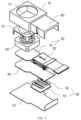
- a camera module 100 includes a housing 10, a lens assembly 20, a circuit board 30, a support plate 40, and a drive assembly 50.
- the housing 10 is provided with an accommodating cavity 11, the lens assembly 20 is movably disposed in the accommodating cavity 11, and the circuit board 30 is connected to the lens assembly 20. At least a portion of the support plate 40 is movably disposed in the accommodating cavity 11, and the lens assembly 20 and the circuit board 30 are disposed on the support plate 40 and move synchronously with the support plate 40.
- the drive assembly 50 is disposed on the housing 10, and at least a portion of the drive assembly 50 is connected to the support plate 40 to drive the support plate 40 to move.
- the camera module 100 mainly includes the housing 10, the lens assembly 20 installed in the housing 10, the circuit board 30 electrically connected to the lens assembly 20, the support plate 40 for limiting the lens assembly 20 and the circuit board 30, and the drive assembly 50 for driving the support plate 40.
- the housing 10 is a basic member of the camera module 100, and the housing 10 can provide an installation foundation for other components of the camera module 100 and protect parts or components such as the drive assembly.
- the housing 10 has the accommodating cavity 11, and the accommodating cavity 11 can accommodate the lens assembly 20.
- the camera module 100 may incline due to shake, which finally affects shooting quality.
- the lens assembly 20 is movable relative to the housing 10, and the lens assembly 20 is driven by the drive assembly 50 to move, to compensate for tilt caused by shake of the camera module 100, effectively preventing shake of the camera module 100.
- the lens assembly 20 and the circuit board 30 can move synchronously with the support plate 40.
- the support plate 40 can be used as a reinforcing plate. Therefore, when the support plate 40 is driven by the drive assembly 50 to move, the lens assembly 20 and the circuit board 30 can move simultaneously. That is, by driving the circuit board 30 to move simultaneously, a problem of relative movement of the lens assembly 20 and the circuit board 30 and of pulling of the circuit board 30 can be prevented.
- types of shift of the lens assembly 20 include movement and rotation, which are not limited herein.
- the drive assembly 50 indirectly drives the lens assembly 20 and the circuit board 30 by the support plate 40.
- the circuit board 30 and the lens assembly 20 can move synchronously, preventing pulling of the lens assembly 20 by a flexible circuit board 5 in related technologies, and preventing the lens assembly 20 according to this embodiment of this application from moving by a longer distance or rotating at a larger angle.
- a defect that a whole structure occupies large space caused by installing the electromagnetic drive system on the camera module in related technologies is prevented.
- a portion of the drive assembly 50 may be installed in the accommodating cavity 11 and connected to the support plate 40, or the drive assembly 50 may be entirely installed outside the accommodating cavity 11 and connected to the support plate 40.
- the portion of the drive assembly 50 may be connected to the support plate 40, or the drive assembly 50 may be entirely connected to the support plate 40.
- a specific installation manner between the drive assembly 50 and the support plate 40 is not limited herein.
- the drive assembly 50 includes, but is not limited to, a motor, and may also be another drive structure that can achieve movement of the support plate 40, such as a drive motor or a transmission mechanism including the drive motor and matching the drive motor.
- the support plate 40 is connected to the lens assembly 20 and the circuit board 30 separately, the support plate 40 is driven by the drive assembly 50 to move, and the lens assembly 20 and the circuit board 30 are driven, by the support plate 40, to move synchronously, so that not only can the lens assembly 20 be prevented from pulling the circuit board 30 during movement, but also space occupied by an overall structure of the camera module 100 can be reduced, facilitating design of stacking of the whole camera module and achieving a miniaturized anti-shake pan-tilt system.
- the housing 10 includes a support 12 and a cover plate 13.
- the support 12 is provided with the accommodating cavity 11 with an opening on a first side.
- the lens assembly 20 may be disposed in the accommodating cavity 11 and move relative to the support 12, and the circuit board 30 may be connected to the lens assembly 20 through the opening.
- the cover plate 13 is disposed on the first side of the support 12, and the drive assembly 50 is disposed on the cover plate 13. In an embodiment, a portion of the drive assembly 50 may be disposed on the cover plate 13, and another portion of the drive assembly 50 may be disposed on the support plate 40 and move relative to the cover plate 13.
- the lens assembly 20 and the circuit board 30 are disposed on the first side of the support plate 40, and the drive assembly 50 is located on a second side of the support plate 40. This not only prevents the drive assembly 50 from occupying space of the lens assembly 20, but also makes full use of space on the second side of the support plate 40 and improves a space utilization rate.
- the camera module 100 is assembled from top to bottom, with a direction close to an observer as a front side and a direction away from the observer as a rear side.
- an accommodating cavity 11 is defined in a support 12, and an opening is provided on a lower side of the support 12.
- a circuit board 30 is disposed on a front side of the support 12, and a cover plate 13 is disposed below the support 12 and the circuit board 30.
- a rear end of the support plate 40 extends between the support 12 and the cover plate 13, and the rear end of the support plate 40, the circuit board 30, and the lens assembly 20 are connected from bottom to top, and the front end of the support plate 40 is disposed between the cover plate 13 and the circuit board 30.
- the drive assembly 50 is disposed on the cover plate 13, and the support plate 40 is driven by the drive assembly 50 to move, so that the circuit board 30 and the lens assembly 20 can be driven to move.
- the circuit board 30 includes a first board body 31 and a second board body 32.
- the first board body 31 is disposed between the lens assembly 20 and the support plate 40.
- the lens assembly 20 is disposed on a first side of the first board body 31.
- a second side of the first board body 31 is connected to the first side of the support plate 40.
- the second board body 32 is disposed on the first side of the support plate 40.
- the second board body 32 is electrically connected to the first board body 31.
- the second board body 32 may be a flexible circuit board, a wire, or the like.
- the first board body 31 is located on a rear side of the second board body 32 and below the lens assembly 20.
- the circuit board 30 is divided into the first board body 31 and the second board body 32, which facilitates connection between the circuit board 30 and the lens assembly 20 and movement of the lens assembly 20 on the premise that the circuit board 30 and the support plate 40 move synchronously.
- the first board body 31 is a circuit board
- the second board body 32 is a flexible circuit board.
- the second board body 32 may be folded along an S-shape, and when the lens assembly 20 moves, the second board body 32 can extend and contract synchronously, expanding a movement range of the lens assembly 20.
- the second board body 32 is disposed opposite to the drive assembly 50, so that space below the second board body 32 can be fully utilized, and an overall structural size of the camera module 100 is prevented from being increased when the drive assembly 50 is placed below the lens assembly 20.
- the housing 10 further includes a wiring box 60, as shown in FIG. 3 , the wiring box 60 may be located on the front side of the support 12, and the second board body 32 and the drive assembly 50 may be located in the wiring box 60 simultaneously, so that accommodating space of the flexible circuit board can be fully utilized.
- a shape of the first board body 31 corresponds to a shape of a first side surface of the lens assembly 20
- the support plate 40 corresponds to a shape of the first board body 31 and a shape of the second board body 32, increasing stability and reliability of an overall structure when the lens assembly 20 and the circuit board 30 move.
- the drive assembly 50 includes a magnetic member 51 and a coil 52.
- One of the magnetic member 51 and the coil 52 is connected to the cover plate 13, and the other of the magnetic member 51 and the coil 52 is connected to the support plate 40.
- the coil 52 is movable relative to the magnetic member 51 after being energized to drive the support plate 40.
- the magnetic member 51 may be disposed on the cover plate 13, and the coil 52 may be disposed on the support plate 40.
- the magnetic member 51 may be disposed on the support plate 40, and the coil 52 may be disposed on the cover plate 13.
- the magnetic member 51 is disposed on an upper end surface of the cover plate 13, and the coil 52 is disposed on a lower end face of the support plate 40.
- the support plate 40 may be a non-magnetic-conductive rigid material.
- the magnetic member 51 and the coil 52 match each other. According to Fleming's left-hand rule, a force perpendicular to a magnetic field direction is generated in the coil 52 that is energized, and the force can control the movement of the support plate 40 when acting on the support plate 40.
- the magnetic member 51 has a plate structure, that is, the magnetic member 51 may be a flat coil, which can effectively save space.
- the magnetic member 51 is attached to the cover plate 13, to facilitate assembly of the magnetic member 51. It should be noted that the magnetic member 51 may also be installed on the cover plate 13 in other installation manners, such as clamping and plugging.
- a quantity of the coils 52 is one, and various types of movement of the support plate 40 can be implemented by one coil 52.
- the coil 52 is a linear conductor, after the linear conductor is energized, the linear conductor moves. When a current direction or magnetic field direction is changed, the linear conductor moves in an opposite direction, so that the support plate 40 can be driven to move.
- the coil 52 is an annular conductor, after the annular conductor is energized, two sides of the annular conductor are subject to forces in different directions, and the annular conductor can rotate around an axis of the annular conductor, to drive the support plate 40 to rotate along a direction.
- the coils 52 are two annular coils, and the two coils 52 are arranged on the support plate 40 at intervals.
- the coil 52 may include a first annular coil and a second annular coil, and the first annular coil and the second annular coil may share a magnet.
- the support plate 40 is a roughly rectangular member.
- a straight line parallel to a length direction of the support plate 40 is a Y axis
- a straight line parallel to a width direction of the support plate 40 is an X axis
- a straight line perpendicular to a plane where the support plate 40 is located is a Z axis.
- Various parts or components of the camera module 100 may be assembled roughly along a Z-axis direction.
- the first annular coil and the second annular coil are located on the upper end surface of the support plate 40 and arranged at intervals along a length direction of the support plate 40. Both the first annular coil and the second annular coil are oval members roughly extending along a width direction of the support plate 40.
- a center line of a connecting line between two coils 52 can share a symmetrical center line with the support plate 40, facilitating force bearing analysis of the support plate 40.
- the coils 52 are not limited, and the coils 52 may also be arranged in another form, which is not limited herein.
- the camera module 100 in this embodiment of this application further includes a position feedback element 70. Positions of the lens assembly 20 and/or the circuit board 30 can be fed back in real time through the position feedback element 70.
- the position feedback element 70 may be connected to the drive assembly 50. A magnitude and direction of a force applied to the support plate 40 can be controlled according to a real-time position of the lens assembly 20 or the circuit board 30, flexibly changing a direction of the lens assembly 20, thereby increasing anti-shake performance of the camera module 100.
- the position feedback element 70 may be a Hall chip or the like, which is not limited herein.
- the position feedback element 70 may be installed at a hollow structure of the annular coil, helping to save space.
- An embodiment of this application further provides an electronic device, including the camera module 100 in any one of the foregoing embodiments.
- the lens assembly 20 may be electrically connected to a motherboard of the electronic device through the circuit board 30, thereby achieving power supply to the lens assembly 20.
- the electronic device may be an action camera, an unmanned aerial vehicle with a pan-tilt, a smart phone, a tablet computer, a wearable device, and the like, which is not limited herein.
Landscapes
- Engineering & Computer Science (AREA)
- Signal Processing (AREA)
- Multimedia (AREA)
- Physics & Mathematics (AREA)
- General Physics & Mathematics (AREA)
- Studio Devices (AREA)
- Adjustment Of Camera Lenses (AREA)
- Camera Bodies And Camera Details Or Accessories (AREA)
Applications Claiming Priority (2)
| Application Number | Priority Date | Filing Date | Title |
|---|---|---|---|
| CN202011542403.0A CN112637470B (zh) | 2020-12-23 | 2020-12-23 | 摄像模组和电子设备 |
| PCT/CN2021/138603 WO2022135247A1 (zh) | 2020-12-23 | 2021-12-16 | 摄像模组和电子设备 |
Publications (2)
| Publication Number | Publication Date |
|---|---|
| EP4270918A1 true EP4270918A1 (de) | 2023-11-01 |
| EP4270918A4 EP4270918A4 (de) | 2024-06-19 |
Family
ID=75321970
Family Applications (1)
| Application Number | Title | Priority Date | Filing Date |
|---|---|---|---|
| EP21909243.4A Pending EP4270918A4 (de) | 2020-12-23 | 2021-12-16 | Kameramodul und elektronische vorrichtung |
Country Status (5)
| Country | Link |
|---|---|
| US (1) | US12439137B2 (de) |
| EP (1) | EP4270918A4 (de) |
| KR (1) | KR102882451B1 (de) |
| CN (1) | CN112637470B (de) |
| WO (1) | WO2022135247A1 (de) |
Families Citing this family (6)
| Publication number | Priority date | Publication date | Assignee | Title |
|---|---|---|---|---|
| CN112637470B (zh) | 2020-12-23 | 2021-12-21 | 维沃移动通信有限公司 | 摄像模组和电子设备 |
| CN112637471B (zh) * | 2020-12-23 | 2022-02-08 | 维沃移动通信有限公司 | 摄像头模组和电子设备 |
| CN115225738A (zh) * | 2021-04-21 | 2022-10-21 | 维沃移动通信有限公司 | 电子设备 |
| WO2023272462A1 (zh) * | 2021-06-29 | 2023-01-05 | 鹏鼎控股(深圳)股份有限公司 | 具有光学防抖功能的摄像模组及其制备方法 |
| US12208739B2 (en) * | 2022-01-13 | 2025-01-28 | Magna Electronics Inc. | Vehicular camera assembly process with enhanced attachment of imager assembly at camera housing |
| US20240337907A1 (en) * | 2023-04-07 | 2024-10-10 | Tdk Taiwan Corp. | Optical element driving mechanism |
Family Cites Families (25)
| Publication number | Priority date | Publication date | Assignee | Title |
|---|---|---|---|---|
| KR100594121B1 (ko) * | 2004-12-17 | 2006-06-28 | 삼성전자주식회사 | 카메라 렌즈 어셈블리의 손떨림 보정 장치 |
| KR100713520B1 (ko) * | 2005-05-31 | 2007-04-30 | 삼성전자주식회사 | 카메라 렌즈 어셈블리의 손떨림 보정 장치 |
| US7558473B2 (en) * | 2005-07-28 | 2009-07-07 | Samsung Electronics Co., Ltd. | Optical image stabilizer for camera lens assembly |
| KR101058679B1 (ko) * | 2009-02-16 | 2011-08-22 | 삼성전자주식회사 | 카메라 렌즈 어셈블리 |
| KR20110127913A (ko) * | 2010-05-20 | 2011-11-28 | 삼성전자주식회사 | 카메라 모듈 |
| US9372352B2 (en) * | 2013-08-23 | 2016-06-21 | Samsung Electro-Mechanics Co., Ltd. | Lens driving device and camera module including the same |
| KR102388119B1 (ko) * | 2015-08-18 | 2022-04-20 | 엘지이노텍 주식회사 | 카메라 장치 및 광학기기 |
| CN204903931U (zh) * | 2015-07-11 | 2015-12-23 | 安徽捷迅光电技术有限公司 | 相机调节机构 |
| CN105158869A (zh) * | 2015-08-12 | 2015-12-16 | 南昌欧菲光电技术有限公司 | 摄像模组及摄像装置 |
| US10663751B2 (en) * | 2016-06-16 | 2020-05-26 | Fotonation Limited | Gimbal adjustment system |
| CN206133092U (zh) * | 2016-10-12 | 2017-04-26 | 广东欧珀移动通信有限公司 | 摄像头模组及具有其的移动终端 |
| CN107135344B (zh) * | 2017-06-15 | 2022-12-16 | 惠州萨至德光电科技有限公司 | 一种微型光学变焦模组 |
| KR102104453B1 (ko) | 2017-11-09 | 2020-05-29 | 삼성전기주식회사 | 카메라 모듈 |
| JP7023691B2 (ja) * | 2017-12-07 | 2022-02-22 | キヤノン株式会社 | 撮像装置およびその制御方法 |
| US11048307B2 (en) | 2018-06-01 | 2021-06-29 | Samsung Electro-Mechanics Co., Ltd. | Dual camera module and portable electronic device |
| KR102704819B1 (ko) * | 2018-06-05 | 2024-09-09 | 삼성전자주식회사 | 렌즈 조립체의 위치에 따라 보정된 신호를 이용하여 조리개를 제어하는 카메라 모듈과, 이를 포함하는 전자 장치 및 이의 운용 방법 |
| CN209151244U (zh) * | 2018-11-21 | 2019-07-23 | 北京小米移动软件有限公司 | 驱动机构、摄像头模组及电子设备 |
| KR102843873B1 (ko) * | 2020-01-10 | 2025-08-08 | 삼성전자주식회사 | 카메라 모듈 및 이를 포함하는 전자 장치 |
| JP2021139988A (ja) * | 2020-03-04 | 2021-09-16 | 日本電産サンキョー株式会社 | 振れ補正機能付き光学ユニット |
| CN111556239B (zh) * | 2020-05-25 | 2022-03-22 | 维沃移动通信有限公司 | 拍摄装置、电子设备及控制方法 |
| CN111654612B (zh) * | 2020-06-17 | 2021-09-03 | 维沃移动通信有限公司 | 摄像模组及电子设备 |
| CN114200618B (zh) * | 2020-09-01 | 2025-07-11 | 新思考电机有限公司 | 光学部件驱动装置、照相机装置以及电子设备 |
| CN212135045U (zh) * | 2020-11-11 | 2020-12-11 | 常州市瑞泰光电有限公司 | 一种镜头驱动装置 |
| CN112637471B (zh) * | 2020-12-23 | 2022-02-08 | 维沃移动通信有限公司 | 摄像头模组和电子设备 |
| CN112637470B (zh) * | 2020-12-23 | 2021-12-21 | 维沃移动通信有限公司 | 摄像模组和电子设备 |
-
2020
- 2020-12-23 CN CN202011542403.0A patent/CN112637470B/zh active Active
-
2021
- 2021-12-16 EP EP21909243.4A patent/EP4270918A4/de active Pending
- 2021-12-16 WO PCT/CN2021/138603 patent/WO2022135247A1/zh not_active Ceased
- 2021-12-16 KR KR1020237025006A patent/KR102882451B1/ko active Active
-
2023
- 2023-06-21 US US18/212,707 patent/US12439137B2/en active Active
Also Published As
| Publication number | Publication date |
|---|---|
| KR102882451B1 (ko) | 2025-11-07 |
| US12439137B2 (en) | 2025-10-07 |
| CN112637470B (zh) | 2021-12-21 |
| US20230336853A1 (en) | 2023-10-19 |
| KR20230124047A (ko) | 2023-08-24 |
| WO2022135247A1 (zh) | 2022-06-30 |
| EP4270918A4 (de) | 2024-06-19 |
| CN112637470A (zh) | 2021-04-09 |
Similar Documents
| Publication | Publication Date | Title |
|---|---|---|
| US12439137B2 (en) | Camera module and electronic device | |
| US12219227B2 (en) | Optical image stabilization module and electronic device | |
| EP3373562B1 (de) | Endgerät mit kameramodul | |
| CN111083340B (zh) | 防抖云台马达、照相装置与电子设备 | |
| CN111405186A (zh) | 摄像模组以及电子设备 | |
| US12470789B2 (en) | Camera module and electronic device | |
| US12401873B2 (en) | Camera module and electronic device | |
| CN112799202B (zh) | 镜头模组 | |
| EP4307653A1 (de) | Kamerastruktur und elektronische vorrichtung | |
| CN112468709B (zh) | 一种云台模组与摄像头模组 | |
| CN115981071A (zh) | 防抖结构、摄像装置及电子设备 | |
| CN214252704U (zh) | 镜头模组 | |
| CN116419047A (zh) | 摄像模组及电子设备 | |
| CN216248617U (zh) | 一种用于镜头模组的驱动装置及镜头模组 | |
| CN113079294B (zh) | 摄像头装置和电子设备 | |
| CN116055833A (zh) | 驱动组件和摄像模组 | |
| CN116055878A (zh) | 驱动组件和摄像模组 | |
| EP4617757A1 (de) | Gleitfokussierungsansteuerungsvorrichtung, linsenmodul und elektronische vorrichtung | |
| CN110300245A (zh) | 一种摄像头模组、手机及移动终端 | |
| CN114244982B (zh) | 摄像模组及电子设备 | |
| WO2026001586A1 (zh) | 一种折叠电路板结构、防抖云台、摄像装置及电子设备 | |
| EP4723654A1 (de) | Verwackelungsschutzanordnung eines bildsensors und kameramodul | |
| CN120786166A (zh) | 摄像头模组和电子设备 | |
| CN112929530A (zh) | 摄像模组、电子设备和电子设备的控制方法 | |
| CN116055880A (zh) | 驱动组件和摄像模组 |
Legal Events
| Date | Code | Title | Description |
|---|---|---|---|
| STAA | Information on the status of an ep patent application or granted ep patent |
Free format text: STATUS: THE INTERNATIONAL PUBLICATION HAS BEEN MADE |
|
| PUAI | Public reference made under article 153(3) epc to a published international application that has entered the european phase |
Free format text: ORIGINAL CODE: 0009012 |
|
| STAA | Information on the status of an ep patent application or granted ep patent |
Free format text: STATUS: REQUEST FOR EXAMINATION WAS MADE |
|
| 17P | Request for examination filed |
Effective date: 20230720 |
|
| AK | Designated contracting states |
Kind code of ref document: A1 Designated state(s): AL AT BE BG CH CY CZ DE DK EE ES FI FR GB GR HR HU IE IS IT LI LT LU LV MC MK MT NL NO PL PT RO RS SE SI SK SM TR |
|
| DAV | Request for validation of the european patent (deleted) | ||
| DAX | Request for extension of the european patent (deleted) | ||
| REG | Reference to a national code |
Ref country code: DE Ref legal event code: R079 Free format text: PREVIOUS MAIN CLASS: H04N0005225000 Ipc: H04N0023680000 |
|
| A4 | Supplementary search report drawn up and despatched |
Effective date: 20240517 |
|
| RIC1 | Information provided on ipc code assigned before grant |
Ipc: H04N 23/57 20230101ALI20240513BHEP Ipc: H04N 23/54 20230101ALI20240513BHEP Ipc: H04M 1/02 20060101ALI20240513BHEP Ipc: H04N 23/68 20230101AFI20240513BHEP |
|
| STAA | Information on the status of an ep patent application or granted ep patent |
Free format text: STATUS: EXAMINATION IS IN PROGRESS |
|
| 17Q | First examination report despatched |
Effective date: 20251001 |