EP4270432A1 - Aktivierungsanordnung mit zwei schaltern und verfahren zum schutz vor unbeabsichtigter aktivierung - Google Patents
Aktivierungsanordnung mit zwei schaltern und verfahren zum schutz vor unbeabsichtigter aktivierung Download PDFInfo
- Publication number
- EP4270432A1 EP4270432A1 EP23155660.6A EP23155660A EP4270432A1 EP 4270432 A1 EP4270432 A1 EP 4270432A1 EP 23155660 A EP23155660 A EP 23155660A EP 4270432 A1 EP4270432 A1 EP 4270432A1
- Authority
- EP
- European Patent Office
- Prior art keywords
- switch
- switches
- actuated
- panel
- switch assembly
- Prior art date
- Legal status (The legal status is an assumption and is not a legal conclusion. Google has not performed a legal analysis and makes no representation as to the accuracy of the status listed.)
- Pending
Links
- 230000004913 activation Effects 0.000 title description 7
- 238000000034 method Methods 0.000 title description 5
- 238000004891 communication Methods 0.000 claims abstract description 32
- 230000008859 change Effects 0.000 claims description 3
- 238000013459 approach Methods 0.000 description 3
- 230000009471 action Effects 0.000 description 2
- 238000010586 diagram Methods 0.000 description 2
- 238000005286 illumination Methods 0.000 description 2
- 206010039203 Road traffic accident Diseases 0.000 description 1
- 230000003213 activating effect Effects 0.000 description 1
- 230000000712 assembly Effects 0.000 description 1
- 238000000429 assembly Methods 0.000 description 1
- 230000004397 blinking Effects 0.000 description 1
- 238000004137 mechanical activation Methods 0.000 description 1
- 238000012986 modification Methods 0.000 description 1
- 230000004048 modification Effects 0.000 description 1
- 230000000007 visual effect Effects 0.000 description 1
Images

Classifications
-
- H—ELECTRICITY
- H01—ELECTRIC ELEMENTS
- H01H—ELECTRIC SWITCHES; RELAYS; SELECTORS; EMERGENCY PROTECTIVE DEVICES
- H01H3/00—Mechanisms for operating contacts
- H01H3/02—Operating parts, i.e. for operating driving mechanism by a mechanical force external to the switch
- H01H3/022—Emergency operating parts, e.g. for stop-switch in dangerous conditions
-
- B—PERFORMING OPERATIONS; TRANSPORTING
- B60—VEHICLES IN GENERAL
- B60K—ARRANGEMENT OR MOUNTING OF PROPULSION UNITS OR OF TRANSMISSIONS IN VEHICLES; ARRANGEMENT OR MOUNTING OF PLURAL DIVERSE PRIME-MOVERS IN VEHICLES; AUXILIARY DRIVES FOR VEHICLES; INSTRUMENTATION OR DASHBOARDS FOR VEHICLES; ARRANGEMENTS IN CONNECTION WITH COOLING, AIR INTAKE, GAS EXHAUST OR FUEL SUPPLY OF PROPULSION UNITS IN VEHICLES
- B60K35/00—Instruments specially adapted for vehicles; Arrangement of instruments in or on vehicles
- B60K35/10—Input arrangements, i.e. from user to vehicle, associated with vehicle functions or specially adapted therefor
-
- H—ELECTRICITY
- H01—ELECTRIC ELEMENTS
- H01H—ELECTRIC SWITCHES; RELAYS; SELECTORS; EMERGENCY PROTECTIVE DEVICES
- H01H23/00—Tumbler or rocker switches, i.e. switches characterised by being operated by rocking an operating member in the form of a rocker button
- H01H23/02—Details
- H01H23/12—Movable parts; Contacts mounted thereon
- H01H23/14—Tumblers
- H01H23/143—Tumblers having a generally flat elongated shape
-
- B—PERFORMING OPERATIONS; TRANSPORTING
- B60—VEHICLES IN GENERAL
- B60K—ARRANGEMENT OR MOUNTING OF PROPULSION UNITS OR OF TRANSMISSIONS IN VEHICLES; ARRANGEMENT OR MOUNTING OF PLURAL DIVERSE PRIME-MOVERS IN VEHICLES; AUXILIARY DRIVES FOR VEHICLES; INSTRUMENTATION OR DASHBOARDS FOR VEHICLES; ARRANGEMENTS IN CONNECTION WITH COOLING, AIR INTAKE, GAS EXHAUST OR FUEL SUPPLY OF PROPULSION UNITS IN VEHICLES
- B60K2360/00—Indexing scheme associated with groups B60K35/00 or B60K37/00 relating to details of instruments or dashboards
- B60K2360/128—Axially displaceable input devices for instruments
-
- B—PERFORMING OPERATIONS; TRANSPORTING
- B60—VEHICLES IN GENERAL
- B60K—ARRANGEMENT OR MOUNTING OF PROPULSION UNITS OR OF TRANSMISSIONS IN VEHICLES; ARRANGEMENT OR MOUNTING OF PLURAL DIVERSE PRIME-MOVERS IN VEHICLES; AUXILIARY DRIVES FOR VEHICLES; INSTRUMENTATION OR DASHBOARDS FOR VEHICLES; ARRANGEMENTS IN CONNECTION WITH COOLING, AIR INTAKE, GAS EXHAUST OR FUEL SUPPLY OF PROPULSION UNITS IN VEHICLES
- B60K2360/00—Indexing scheme associated with groups B60K35/00 or B60K37/00 relating to details of instruments or dashboards
- B60K2360/131—Pivotable input devices for instruments
-
- B—PERFORMING OPERATIONS; TRANSPORTING
- B60—VEHICLES IN GENERAL
- B60K—ARRANGEMENT OR MOUNTING OF PROPULSION UNITS OR OF TRANSMISSIONS IN VEHICLES; ARRANGEMENT OR MOUNTING OF PLURAL DIVERSE PRIME-MOVERS IN VEHICLES; AUXILIARY DRIVES FOR VEHICLES; INSTRUMENTATION OR DASHBOARDS FOR VEHICLES; ARRANGEMENTS IN CONNECTION WITH COOLING, AIR INTAKE, GAS EXHAUST OR FUEL SUPPLY OF PROPULSION UNITS IN VEHICLES
- B60K2360/00—Indexing scheme associated with groups B60K35/00 or B60K37/00 relating to details of instruments or dashboards
- B60K2360/20—Optical features of instruments
- B60K2360/33—Illumination features
- B60K2360/34—Backlit symbols
-
- B—PERFORMING OPERATIONS; TRANSPORTING
- B60—VEHICLES IN GENERAL
- B60K—ARRANGEMENT OR MOUNTING OF PROPULSION UNITS OR OF TRANSMISSIONS IN VEHICLES; ARRANGEMENT OR MOUNTING OF PLURAL DIVERSE PRIME-MOVERS IN VEHICLES; AUXILIARY DRIVES FOR VEHICLES; INSTRUMENTATION OR DASHBOARDS FOR VEHICLES; ARRANGEMENTS IN CONNECTION WITH COOLING, AIR INTAKE, GAS EXHAUST OR FUEL SUPPLY OF PROPULSION UNITS IN VEHICLES
- B60K2360/00—Indexing scheme associated with groups B60K35/00 or B60K37/00 relating to details of instruments or dashboards
- B60K2360/60—Structural details of dashboards or instruments
- B60K2360/68—Features of instruments
- B60K2360/693—Cover plate features
-
- H—ELECTRICITY
- H01—ELECTRIC ELEMENTS
- H01H—ELECTRIC SWITCHES; RELAYS; SELECTORS; EMERGENCY PROTECTIVE DEVICES
- H01H2231/00—Applications
- H01H2231/026—Car
-
- H—ELECTRICITY
- H01—ELECTRIC ELEMENTS
- H01H—ELECTRIC SWITCHES; RELAYS; SELECTORS; EMERGENCY PROTECTIVE DEVICES
- H01H2300/00—Orthogonal indexing scheme relating to electric switches, relays, selectors or emergency protective devices covered by H01H
- H01H2300/024—Avoid unwanted operation
-
- H—ELECTRICITY
- H01—ELECTRIC ELEMENTS
- H01H—ELECTRIC SWITCHES; RELAYS; SELECTORS; EMERGENCY PROTECTIVE DEVICES
- H01H2300/00—Orthogonal indexing scheme relating to electric switches, relays, selectors or emergency protective devices covered by H01H
- H01H2300/054—Application timeslot: duration of actuation or delay between or combination of subsequent actuations determines selected function
Definitions
- Automobiles include an increasing amount of electronics and associated functionality. Many vehicles include components that provide wireless communication functions that facilitate communications with devices remote from the vehicle. For example, some vehicles include an emergency call button to request emergency services, such as in the event of a traffic accident.
- the invention seeks to address identified drawbacks or at least provide automakers and/or the public with an alternative.
- a switch assembly for a vehicle may comprise: a first switch; a second switch that is adjacent the first switch and actuatable independent of actuation of the first switch; a switch actuator that presents a surface in an interior of the vehicle for a user to contact to selectively actuate the first and second switches; and a processor configured to initiate a communication function based on determining when the first and second switches are actuated in a predefined manner.
- the predefined manner may comprise the first and second switches being actuated simultaneously or the first and second switches being individually actuated within a predefined time. Alternatively or in addition, the predefined manner may comprise a predefined sequence of actuation.
- a communication function is less likely to be inadvertently activated because at least two switches must be actuated, either simultaneously or within a relatively short predetermined time, before a call is made. This avoids unnecessary costs incurred or having to rescind an emergency call or other request.
- a switch assembly for a vehicle includes a first switch and a second switch that is adjacent the first switch.
- the first and second switches are actuatable independent of actuation of the other one of the switches.
- a switch actuator presents a surface in an interior of the vehicle for a user to contact to selectively actuate the first and second switches.
- a processor is configured to initiate a communication function based on determining that the first and second switches were actuated in a predefined manner.
- the predefined manner may comprise the first and second switches being actuated simultaneously or the first and second switches being individually actuated within a predefined time.
- the switch actuator may comprise a panel that is configured to be pivoted about a pivot portion of the panel (e.g. at a centre thereof) toward a first side to actuate the first switch and toward a second side to actuate the second switch; and the switch actuator allows for the first and second switches to be actuated individually within the predefined time.
- the panel is actuated in a rocking motion and, in this way, a mechanical activation element is provided to implement the function of the invention at least for individual activation within a predefined time. According to this and other examples herein there is no need to add additional parts like a flap with latch and spring as in prior art solutions.
- the processor is configured to initiate the communication function only based on determining that the first and second switches were actuated individually within the predefined time.
- the first and second switches are situated on opposite sides of a support; and a mid- or central- portion of the panel is connected to the support in a manner that allows the panel to be pivoted.
- one of the support and the mid or central portion of the panel comprises a rod; and the other of the central portion of the panel and the support comprises a clip that engages the rod; and the clip is rotatable about the rod to pivot the panel toward the first side and toward the second side. In this way, a proximate connection between an end of the rod and clip enables pivoting movement.
- the switch assembly includes an indicator configured to provide an indication that one of the switches has been actuated and the other of the switches has to be actuated within the predefined time to initiate the communication function.
- the indicator comprises a visible symbol and the indication comprises a change in an appearance of the visible symbol.
- the visible symbol is located on the switch actuator, i.e. in a position visible to the user.
- the appearance of the visible symbol corresponds to the communication function.
- the switch actuator comprises a first moveable portion for actuating the first switch and a second moveable portion for actuating the second switch; the first moveable portion is moveable independent of movement of the second moveable portion; and the processor initiates the communication function based on determining that the first and second switches were actuated simultaneously or the first and second switches were individually actuated within the predefined time. In this way, it is possible to determine an intentional activation of the switch assembly before a communication function is initiated.
- a predefined manner of implementation comprises the first switch being actuated before the second switch or the second switch being actuated before the first switch.
- Disclosed example embodiments and others like them facilitate a communication function, such as placing a call for emergency services from a vehicle.
- a switch assembly and control method make it simple for an individual to activate the communication function and guards against unintentional activation.
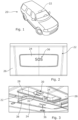
- Figure 1 shows a vehicle 20 including a switch assembly 22 that is configured to activate a communication function.
- the switch assembly 22 is at least partially situated inside the vehicle interior, e.g. in a ceiling portion, where an individual in the vehicle can access the switch assembly 22 when the communication function is desired.
- An emergency services request or call is an example communication function that is discussed in the following description. Switch assemblies designed according to an embodiment of this invention may be useful for other communication functions.
- the switch assembly 22 of this example embodiment includes a switch actuator panel 24 that is situated to present a surface that can be contacted or touched by an individual in the interior of the vehicle 20.
- an interior surface 26, which may be part of a headliner, for example, includes a recess 28.
- the panel 24 is received into the recess 28 and maintained in place by a support 30.
- the support 30 includes at least one rod 32 (e.g. male connector) within the recess 28 and a central portion of the panel 24 includes at least one clip 34 (e.g. female receiving portion) that engages the rod 32.
- the panel 24 may include at least one rod and the support 30 includes a clip that cooperates with the rod to hold the panel 24 in place.
- the panel 24 includes an indicator 36 on an outer side facing toward the vehicle interior.
- the indicator 36 includes a visible symbol that provides a visual indication of the function associated with the switch assembly 22.
- the visible symbol in some embodiments includes an icon, letters, or a combination of them.
- An opposite side of the panel 24 includes at least one switch actuating boss 38.
- the panel 24 is supported for pivotal movement relative to the interior surface 26 to allow a first side of the panel 24 to be pressed so the first switch actuating boss 38 contacts and actuates a first switch 40.
- the clip 34 rotates about the rod 32 and the panel 24 pivots in a see-saw action as schematically represented by the arrow 42.
- a second side of the panel 24 includes a second switch actuating boss 44 that is positioned to actuate a second switch 46 when the second side of the panel 24 is pressed toward the second switch 46. It will be apparent that the arrangement allows a see-saw action where either of the first or second switch could be activated before the other.
- the first switch 40 and the second switch 46 can be any known switch that is actuated by contact or pressure.
- a processor 50 determines if/when the switches 40 and 46 have been actuated and instigates the corresponding communication function, such as controlling a transceiver 52 to place a call for emergency services.
- Figure 5 illustrates a flowchart diagram 60 that summarizes an example method of controlling operation of the communication function.
- the processor 50 determines when one of the first switch 40 or the second switch 46 has been actuated, which would occur when a user presses on the corresponding side of the panel 24 to pivot that side into engagement with the corresponding switch 40 or 46.
- the processor 50 determines whether the other of the first and second switches 40, 46 has been actuated. In this example embodiment, an emergency services call will only be initiated by the processor 50 if the first switch 40 and the second switch 46 have both been pressed within a preselected time.
- An example predetermined time is two seconds, but aby suitable time period may be implemented, such as 0.5 to five seconds.
- the processor determines whether the predefined time has expired at decision box 66. If there is still time remaining, the processor 50 continues to monitor for actuation of the other switch.
- the processor 50 positively initiates the communication function at box 68. However, if only one of the switches 40, 46 has been actuated and the predefined time elapses before the other switch is actuated, the processor 50 resets at box 70 and does not initiate an emergency services call.
- the panel 24 cannot be manipulated in a manner that would simultaneously actuate both of the switches 40 and 46.
- the only way a user can initiate an emergency services call in such an embodiment is by pressing on one side of the panel 24 and then the other within the predefined time (the instructions for which may be contained in a manual or stated in text adjacent or on the panel 24).
- the processor 50 is programmed or otherwise configured to recognize an initial switch actuation of either the first switch 40 or the second switch 46 followed by actuation of the other switch within the predefined time as an indication that an emergency services call is intended.
- the indicator 36 includes a visible symbol having a light or a color that can be controlled by the processor 50.
- Figure 5 includes a functional block for activating the indicator at dotted line box 72 when only one of the switches 40, 46 has been actuated and the predefined time has not yet expired.
- the switch assembly 22 provides a prompt to the individual who actuated one of the switches to actuate the other switch to place an emergency call. While the indicator 36 is activated at box 72 in this example embodiment, other embodiments may include an indicator that is in another location within the vehicle interior.
- the indicator 36 includes an illuminated visible symbol on or near each depressible end of the panel 24.
- Each lighted symbol may be a first color, such as green, when the communication function is in a sleep or inactive state.
- the processor 50 changes the illumination of the visible symbol on the other side of the panel 24.
- changing the illumination includes changing the color to a second color, causing the light to flash, or a combination of these.
- the visible symbol on the side of the panel 24 that has not yet been pressed changes to a second color, such as red, and flashes.
- the processor 50 causes the second color light to continue flashing until that side of the panel 24 is pressed to activate the corresponding switch or the time limit expires. If the individual user presses that side soon enough, the processor 50 causes the visible symbol to remain the second color and stop blinking to indicate that the communication function has been instigated. If that side of the panel 24 is not pressed soon enough and the time limit expires, the processor 50 causes both visible symbols to change back to the first color indicating that the communication function was not performed.
- Some embodiments may include an audible indicator that provides an audible prompt to press the other side of the panel 24 to actuate the other switch.
- An individual who inadvertently actuated one of the switches 40, 46 and does not desire to place an emergency services call can interpret the prompt as a warning not to press the other side of the panel to avoid placing a call.
- instructions may require a specified side of the panel 24/button to be pressed first, so that a positive intent to initiate a communication request is registered.
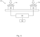
- Figure 6 shows another example embodiment that does not include a pivotable panel to actuate the switches 40 and 46.
- the switch actuator includes a first moveable portion 74 that can be manipulated or pressed to actuate the first switch 40 and an independent second moveable portion 76 that can be manipulated or pressed to actuate the second switch 46.
- the first moveable portion 74 and the second moveable portion 76 may be buttons, for example.
- the processor 50 in the embodiment of Figure 6 can operate according to the flow chart 60 of Figure 5 .
- the processor 50 may recognize an order in which the switches 40, 46 are actuated (or either order if a precise order is not essential) within a predetermined time period as a command to place an emergency call. Or particularly in this embodiment, it is possible for both switches to be actuated practically simultaneously if an individual presses both moveable portions 74 and 76 at once. In that case, the processor recognizes that both switches were actuated within the predefined time (e.g. a very short time period, almost zero) and the condition at decision box 64 is satisfied at the same time that the switch actuation is detected at box 62.
- the predefined time e.g. a very short time period, almost zero
- a possible variation includes the implementation of at least one touch sensitive and/or haptic zone (e.g. to activate or function as the first and/or second switches), that is not necessarily mechanically depressible, e.g. in place of the illustrated buttons 74, 76 of Figure 6 .
- the first and second switches could be regarded as integrated with the switch actuator.
- a further variation may include a third switch or a third or further activation of either the first or second switch, in order to initiate the communication function.
- the switches may be activated in sequence 1-2-1 within a predetermined time period according to instructions configured for the processor.
- a switch assembly for a vehicle includes a first switch and a second switch that is adjacent the first switch.
- the first and second switches are actuatable independently of actuation of the other one of the switches.
- a switch actuator presents a surface in an interior of the vehicle for a user to press/contact to selectively actuate the first and second switches.
- a processor is configured to initiate a communication function, e.g. an emergency call, based on determining when the first and second switches have been actuated in a predefined manner, i.e. that the first and second switches have been actuated simultaneously or individually actuated within a predefined time.
Landscapes
- Engineering & Computer Science (AREA)
- Chemical & Material Sciences (AREA)
- Combustion & Propulsion (AREA)
- Transportation (AREA)
- Mechanical Engineering (AREA)
- Switch Cases, Indication, And Locking (AREA)
- Push-Button Switches (AREA)
Priority Applications (1)
| Application Number | Priority Date | Filing Date | Title |
|---|---|---|---|
| US18/176,118 US20230286433A1 (en) | 2022-03-09 | 2023-02-28 | Two-Switch Function Activation Assembly And Method Of Guarding Against Unintentional Activation |
Applications Claiming Priority (1)
| Application Number | Priority Date | Filing Date | Title |
|---|---|---|---|
| US202263318052P | 2022-03-09 | 2022-03-09 |
Publications (1)
| Publication Number | Publication Date |
|---|---|
| EP4270432A1 true EP4270432A1 (de) | 2023-11-01 |
Family
ID=85222370
Family Applications (1)
| Application Number | Title | Priority Date | Filing Date |
|---|---|---|---|
| EP23155660.6A Pending EP4270432A1 (de) | 2022-03-09 | 2023-02-08 | Aktivierungsanordnung mit zwei schaltern und verfahren zum schutz vor unbeabsichtigter aktivierung |
Country Status (2)
| Country | Link |
|---|---|
| EP (1) | EP4270432A1 (de) |
| CN (1) | CN116741556A (de) |
Citations (5)
| Publication number | Priority date | Publication date | Assignee | Title |
|---|---|---|---|---|
| DE10016891A1 (de) * | 2000-04-05 | 2001-10-18 | Volkswagen Ag | Betätigungseinrichtung für Notrufauslösung bei Kraftfahrzeugen |
| US20040245856A1 (en) * | 2003-06-09 | 2004-12-09 | Shoei-Lai Chen | Electrical switching device for preventing error pushing |
| US20060061543A1 (en) * | 2004-09-21 | 2006-03-23 | Fujitsu Limited | Electronic apparatus and method of controlling image on screen |
| US8872676B2 (en) * | 2011-08-01 | 2014-10-28 | Toyota Motor Engineering & Manufacturing North America, Inc. | Systems and methods for switching |
| US11189437B2 (en) * | 2016-10-27 | 2021-11-30 | Hilti Aktiengesellschaft | Switch device for a power tool |
-
2023
- 2023-02-08 EP EP23155660.6A patent/EP4270432A1/de active Pending
- 2023-03-06 CN CN202310205950.7A patent/CN116741556A/zh active Pending
Patent Citations (5)
| Publication number | Priority date | Publication date | Assignee | Title |
|---|---|---|---|---|
| DE10016891A1 (de) * | 2000-04-05 | 2001-10-18 | Volkswagen Ag | Betätigungseinrichtung für Notrufauslösung bei Kraftfahrzeugen |
| US20040245856A1 (en) * | 2003-06-09 | 2004-12-09 | Shoei-Lai Chen | Electrical switching device for preventing error pushing |
| US20060061543A1 (en) * | 2004-09-21 | 2006-03-23 | Fujitsu Limited | Electronic apparatus and method of controlling image on screen |
| US8872676B2 (en) * | 2011-08-01 | 2014-10-28 | Toyota Motor Engineering & Manufacturing North America, Inc. | Systems and methods for switching |
| US11189437B2 (en) * | 2016-10-27 | 2021-11-30 | Hilti Aktiengesellschaft | Switch device for a power tool |
Also Published As
| Publication number | Publication date |
|---|---|
| CN116741556A (zh) | 2023-09-12 |
Similar Documents
| Publication | Publication Date | Title |
|---|---|---|
| JP2628819B2 (ja) | ドアトリム用ユニットパネル | |
| US9931974B2 (en) | Lighting system for a motor vehicle and motor vehicle having a lighting system | |
| CN105425995B (zh) | 利用触摸屏技术和触觉反馈的开关阵列 | |
| US20010004044A1 (en) | Multiple switch device | |
| US20100052931A1 (en) | Gesture control key fob | |
| US5949207A (en) | Auto window switch and obstacle detect/protect with override | |
| US20150235782A1 (en) | Emergency button for vehicle | |
| US11441335B2 (en) | Vehicular portable device | |
| JPH07272591A (ja) | 自動車用ドアロックスイッチ | |
| US20140172186A1 (en) | Capacitive steering wheel switches with audible feedback | |
| JP2018185915A (ja) | 車両用スイッチ装置 | |
| EP4270432A1 (de) | Aktivierungsanordnung mit zwei schaltern und verfahren zum schutz vor unbeabsichtigter aktivierung | |
| US20230286433A1 (en) | Two-Switch Function Activation Assembly And Method Of Guarding Against Unintentional Activation | |
| CN112673144A (zh) | 电动窗同步开关 | |
| JP6211288B2 (ja) | 車両用オートドア操作装置、および車両に設けられる装飾部品 | |
| US20220048390A1 (en) | Roof Console for a Vehicle | |
| CN105304370A (zh) | 车辆用开关装置 | |
| KR101489254B1 (ko) | 차량용 정전식 터치 스위치 장치 | |
| KR100511408B1 (ko) | 파워윈도우 스위치 | |
| CN214956575U (zh) | 车辆的控制旋钮组件和车辆 | |
| KR20180016923A (ko) | 차량용 스티어링 휠 | |
| CN110651245A (zh) | 家用器具的无障碍操作 | |
| US20210094484A1 (en) | Vehicle information conveying device | |
| JP2006079407A (ja) | 入力装置及びこれを用いた入力ユニット | |
| EP3670234B1 (de) | Anordnung einer bedieneinheit in einem kraftfahrzeug |
Legal Events
| Date | Code | Title | Description |
|---|---|---|---|
| PUAI | Public reference made under article 153(3) epc to a published international application that has entered the european phase |
Free format text: ORIGINAL CODE: 0009012 |
|
| STAA | Information on the status of an ep patent application or granted ep patent |
Free format text: STATUS: THE APPLICATION HAS BEEN PUBLISHED |
|
| AK | Designated contracting states |
Kind code of ref document: A1 Designated state(s): AL AT BE BG CH CY CZ DE DK EE ES FI FR GB GR HR HU IE IS IT LI LT LU LV MC ME MK MT NL NO PL PT RO RS SE SI SK SM TR |
|
| RAP1 | Party data changed (applicant data changed or rights of an application transferred) |
Owner name: APTIV TECHNOLOGIES AG |
|
| STAA | Information on the status of an ep patent application or granted ep patent |
Free format text: STATUS: REQUEST FOR EXAMINATION WAS MADE |