EP4270016A2 - Temperature dependent calibration of movement detection devices - Google Patents
Temperature dependent calibration of movement detection devices Download PDFInfo
- Publication number
- EP4270016A2 EP4270016A2 EP23195266.4A EP23195266A EP4270016A2 EP 4270016 A2 EP4270016 A2 EP 4270016A2 EP 23195266 A EP23195266 A EP 23195266A EP 4270016 A2 EP4270016 A2 EP 4270016A2
- Authority
- EP
- European Patent Office
- Prior art keywords
- thermal
- electronics
- structural material
- temperature
- region
- Prior art date
- Legal status (The legal status is an assumption and is not a legal conclusion. Google has not performed a legal analysis and makes no representation as to the accuracy of the status listed.)
- Granted
Links
Images





Classifications
-
- G—PHYSICS
- G01—MEASURING; TESTING
- G01C—MEASURING DISTANCES, LEVELS OR BEARINGS; SURVEYING; NAVIGATION; GYROSCOPIC INSTRUMENTS; PHOTOGRAMMETRY OR VIDEOGRAMMETRY
- G01C25/00—Manufacturing, calibrating, cleaning, or repairing instruments or devices referred to in the other groups of this subclass
- G01C25/005—Manufacturing, calibrating, cleaning, or repairing instruments or devices referred to in the other groups of this subclass initial alignment, calibration or starting-up of inertial devices
-
- G—PHYSICS
- G01—MEASURING; TESTING
- G01D—MEASURING NOT SPECIALLY ADAPTED FOR A SPECIFIC VARIABLE; ARRANGEMENTS FOR MEASURING TWO OR MORE VARIABLES NOT COVERED IN A SINGLE OTHER SUBCLASS; TARIFF METERING APPARATUS; MEASURING OR TESTING NOT OTHERWISE PROVIDED FOR
- G01D18/00—Testing or calibrating apparatus or arrangements provided for in groups G01D1/00 - G01D15/00
-
- B—PERFORMING OPERATIONS; TRANSPORTING
- B81—MICROSTRUCTURAL TECHNOLOGY
- B81B—MICROSTRUCTURAL DEVICES OR SYSTEMS, e.g. MICROMECHANICAL DEVICES
- B81B7/00—Microstructural systems ; Auxiliary parts of microstructural devices or systems
- B81B7/02—Microstructural systems ; Auxiliary parts of microstructural devices or systems containing distinct electrical or optical devices of particular relevance for their function, e.g. microelectro-mechanical systems [MEMS]
-
- G—PHYSICS
- G01—MEASURING; TESTING
- G01P—MEASURING LINEAR OR ANGULAR SPEED, ACCELERATION, DECELERATION, OR SHOCK; INDICATING PRESENCE, ABSENCE, OR DIRECTION, OF MOVEMENT
- G01P21/00—Testing or calibrating of apparatus or devices covered by the preceding groups
-
- B—PERFORMING OPERATIONS; TRANSPORTING
- B81—MICROSTRUCTURAL TECHNOLOGY
- B81B—MICROSTRUCTURAL DEVICES OR SYSTEMS, e.g. MICROMECHANICAL DEVICES
- B81B2201/00—Specific applications of microelectromechanical systems
- B81B2201/02—Sensors
- B81B2201/0228—Inertial sensors
- B81B2201/0235—Accelerometers
-
- B—PERFORMING OPERATIONS; TRANSPORTING
- B81—MICROSTRUCTURAL TECHNOLOGY
- B81B—MICROSTRUCTURAL DEVICES OR SYSTEMS, e.g. MICROMECHANICAL DEVICES
- B81B2201/00—Specific applications of microelectromechanical systems
- B81B2201/02—Sensors
- B81B2201/0228—Inertial sensors
- B81B2201/0242—Gyroscopes
Definitions
- This invention relates generally to an electronics system, a method of constructing an electronics system and a method of operating an electronics device, and more specifically to calibration of movement detection devices.
- Electronics devices such as semiconductor chips frequently include movement detection devices such as accelerometers and gyroscopes.
- An accelerometer can detect acceleration of the electronics device in a specified direction and a gyroscope can detect a change in angle of the electronics device.
- Such measurement devices are usually manufactured using microelectromechanical systems (MEMS) technology.
- MEMS microelectromechanical systems
- the invention provides an electronics system including a board.
- the board may include a structural material, a thermal conduit on the structural material, the thermal conduit having a thermal conductivity that is higher than a thermal conductivity of the structural material and having a first region, a second region, and a connecting portion connecting the first region to the second region, a thermal interface on the structural material, the thermal interface having a thermal heat transfer capacity that is higher than the thermal heat transfer capacity of the structural material and being attached to the first region of the thermal conduit and an electronics device mounted to the board at the second region of the thermal conduit, the thermal conduit forming a thermal path between the surface of the thermal interface and the electronics device.
- the invention also provides a method of constructing an electronics system including constructing a board that may include forming a thermal conduit on the structural material, the thermal conduit having a thermal heat transfer capacity that is higher than a thermal heat transfer capacity of the structural material and having a first region, a second region, and a connecting portion connecting the first region to the second region, forming a thermal interface on the structural material, the thermal interface having a thermal heat transfer capacity conductivity that is higher than the thermal heat transfer capacity of the structural material and being attached to the first region of the thermal conduit and mounting an electronics device to the board at the second region of the thermal conduit, the thermal conduit forming a thermal path between the surface of the thermal interface and the electronics device.
- the invention further provides a method of operating an electronics device including operating an electronics device mounted to a board, locating a thermal device adjacent a thermal interface of the board formed on a structural material of the board and transferring heat between the thermal device and the electronics device through a thermal conduit on the structural material, the thermal conduit having a thermal heat transfer capacity that is higher than a thermal heat transfer capacity of the structural material and having a first region attached to the thermal interface, a second region at the electronics device, and a connecting portion connecting the first region to the second region.
- Output readings from movement detection devices can be affected by changes in temperature of the devices, thereby introducing temperature-dependent error in the output measurements.
- movement detection devices such as accelerometers and gyroscopes
- an accelerometer at rest should provide an output measurement corresponding to gravitational acceleration; however when the accelerometer is subjected to different temperatures, the output measurement will be different due to error associated with the accelerometer being at a higher temperature. Because the output should not change while the accelerometer is at rest, that is, acceleration is still only gravity regardless of the temperature, it is possible to isolate the output measurement error associated with temperature by finding the difference (or "offset") between the erroneous measurement and the known baseline measurement (gravity in the case of an accelerometer).
- the collection of data associating temperatures with specific offset readings can be compiled for each movement detection device during the calibration process.
- the data can be stored as calibration data in a table for look up or extrapolation, or can be used to define a best fit function.
- the calibration data can be accessed by a virtual reality, augmented reality, or mixed reality system to obtain an adjusted measurement from a movement detection device given the temperature of the movement detection device and its initial "raw" measurement.
- a calibration system and process that improves calibration accuracy is described herein.
- Known methods of calibrating movement detection devices involve contacting the movement detection device with a thermal probe to introduce heat by conduction or require actively blowing air across the movement detection device to adjust its temperature by convection. Both of these methods can cause the device to move so that a measurement taken from the device during calibration will include an error associated with temperature and an error associated with movement introduced by the measurement method. Because it is not possible to know how much movement is introduced by the measurement method, it is not possible to isolate the error associated with temperature. As a result, the error cannot be accurately removed from the raw output measurement of the device.
- Figures 1 , 2 and 3 illustrate an electronics system 10, according to an embodiment of the disclosure.
- Figure 1 is a top view of an example configuration of a board 12 in the electronics system 10.
- Figure 2 is a cross-sectional side view on 2-2 in Figure 1 .
- Figure 3 is a cross-sectional side view on 3-3 in Figure 1 .
- the electronics system 10 includes a board 12 made up of multiple layers of different materials. The layers and various features disposed therein provide particular functions during calibration and use of an electronics device 14 (discussed with respect to Figures 4 and 5 ), such as a sensor or sensor suite, connected to the board 12.
- the board 12 is constructed from structural material 22, such as FR4 dielectric, and a thermally and electrically conductive material, such as metal components 24.
- Metal components 24 may include a copper material.
- the metal of the metal components 24 is more thermally conductive, and therefore has a higher thermal heat transfer capacity, than the structural material 22.
- the metal of the metal components 24 is electrically conductive and the structural material 22 is electrically insulating.
- the metal components 24 are disposed between the layers of structural material 22.
- the metal components 24 can include first, second and third metal layers 34, 36 and 38 separated by the first and second structural layers 28 and 30.
- the board 12 further includes top and bottom insulating layers 32 and 26 that cover the first and third metal layers 34 and 38.
- the top and bottom insulating layers 32 and 26 can include an electrically insulating solder resist material 25.
- the metal components 24 also include first and second sets of vias 40 and 42, respectively.
- the first set of vias 40 connects portions of the first metal layer 34 to portions of the second metal layer 36.
- the second set of vias 42 connects portions of the second metal layer 36 to portions of the third metal layer 38.
- the metal layers 34, 36 and 38 are thereby electrically and thermally connected to one another.
- the metal layers 34, 36 and 38 together with the first and second sets of vias 40 and 42 form a thermal conduit of thermally conductive material that connect a first region 46 of the thermal conduit to a second region 48 of the thermal conduit.
- Portions of the third metal layer 38 are isolated as metal lines 76 to function as traces for electrical signals. These metal lines 76 can be isolated from each other and from other metal components 24 such that each line is surrounded by non-conductive material, such as dielectric structural material 22 and insulating solder resist material 25.
- non-conductive material such as dielectric structural material 22 and insulating solder resist material 25.
- the metal lines 76 may be disposed in one or more of the metal layers in the board 12. Additionally, while the lines 76 are shown as exposed parts of the metal component 24, portions of the metal lines 76 can also be coated with the insulating solder resist material 25.
- the metal components 24 further include a thermal interface 52.
- the thermal interface 52 is an area of the third metal layer 38 at the first region 46 that has been exposed by removing a portion of the top insulating layer 32.
- the thermal interface 52 is an upper surface 54 of third metal layer 38 that is exposed and is configured to contact part of an electronic device calibration station 80.
- the upper surface 54 forms only a portion of an upper surface of the board 12, with the remainder of the upper surface consisting of an upper surface of the structural layer 30 and insulating solder resist layer 32.
- the first, second, and third metal layers 34, 36, 38 have an inner portion 58 and an outer portion 60.
- the structural material 22 forms a plurality of barriers 62 that distinguish the inner portion 58 from the outer portion 60.
- the barriers 62 act as thermal barriers to prevent heat from conducting from the inner portion 58 to the outer portion 60 of the second metal layer 36, or at least substantially slow the transfer of heat so that the outer portion 60 is kept cooler than the inner portion 58.
- Additional electronic components can be connected to the board 12. Such components can be connected to the board 12 at the outer portion 60 to keep the components from experiencing high heat during the calibration process.
- first, second, and third metal layers 34, 36, 38 also have connecting portions 64 that connect the inner portion 58 to the outer portion 60.
- the connecting portions 64 ensure that the metal layers are electrically grounded such that there is an equal reference voltage between the inner portion 58 and the outer portion 60.
- thermal barriers 62 are formed at one or more positions within the first, second and third metal layers 34, 36 and 38 ( Figure 1 ) and that each metal layer has respective portions 64 connecting inner and outer regions thereof.
- the barriers 62 prevent, or at least slow heat transfer from the inner portion 58 to the outer portion 60 to protect other components attached to the board 12 from experiencing high temperatures during the calibration of electronics device 14.
- the electronics system 10 further includes an electronics device 14 and a system storage 18.
- the electronics device 14 is mounted to an upper surface of the board 12 through connections 74.
- the electronics device 14 and the thermal interface 52 are within the barriers 62 that define the inner portion 58.
- the electronics device 14 is mounted above the second region 48 of the thermal conduit described above.
- the electronics system 10 further includes a board interface 16 that is attached to the board 12 and connected to the measurement devices in the electronics device 14.
- the electronics device 14 includes a structural body 66 and a number measurement devices in the structural body 66.
- the measurement devices include a temperature sensor 68 and two movement detection device in the form of an accelerometer 70 and a gyroscope 72. Although two movement detection devices are used for purposes of this embodiment, it may be possible to implement aspects of the invention using only one measurement device. It may for example be possible to calibrate an electronics device having only a gyroscope or only an accelerometer.
- the structural body 66 may, for example, be a silicon or other semiconductor structural body that may be packaged using conventional packaging technologies.
- the temperature sensor 68, accelerometer 70 and gyroscope 72 are connected through connectors 74 on an upper surface of the board 12 and metal lines 76 in the board 12 to the board interface 16. Data traces from the temperature sensor 68, accelerometer 70, and gyroscope 72 are routed to a microprocessor 73 in the structural body 66 which serves as an input/output interface for the measurement devices.
- the system storage 18 serves to store calibration data received from the calibration station 80 that is associated with the accelerometer 70 and gyroscope 72.
- the system storage 18 may, for example, include a solid-state memory.
- the system storage 18 is shown near the electronics device 14, however, the system storage may be a remote storage, located on a cloud-based storage or on another area of the electronics device such that it is not in contact with the board 12.
- the system storage 18 may be located anywhere that is in communication with electronics device 14 to allow for data transfer between electronics device 14 and system storage 18.
- the system storage 18 includes no calibration data immediately after the electronics system 10 has been assembled (that is, prior to undergoing calibration) but is uniquely associated with the electronics device 14 by enabling data to transfer between the electronics device 14 and the system storage 18.
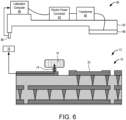
- FIG. 6 further illustrates a calibration station 80 that is used to calibrate the accelerometer 70 and the gyroscope 72.
- the calibration station 80 includes a frame 82, a calibration computer 84, a calibration computer interface 86, a thermoelectric device 88, a transformer 90 and an electric power connector 92.
- the components of the calibration station 80 are mounted in a stationary position to one another via the frame 82.
- a spacing between the calibration computer interface 86 and the thermoelectric device 88 is the same as a spacing between the board interface 16 and the thermal interface 52.
- the calibration computer 84 is connected to the calibration computer interface 86 so that signals can transmit between the calibration computer 84 and the calibration computer interface 86. Information from the microprocessor 73 can be accessed by the calibration station 80.
- the calibration computer 84 is connected to the electric power connector 92 so that power can be provided through the electric power connector 92 to the calibration computer 84.
- the thermoelectric device 88 is connected through the transformer 90 to the electric power connector 92. The power can be provided by the electric power connector 92 through the transformer 90 to the thermoelectric device 88.
- the transformer 90 reduces the voltage provided by the electric power connector 92 before providing power to the thermoelectric device 88.
- the thermoelectric device 88 is preferably a reversible heat pump, such as a thermoelectric cooler, capable of providing heat into the board 12 or drawing heat out of the board 12. The flexibility to achieve a wide range of temperatures on the board 12, and thus at the electronics device 14, can improve calibration accuracy of the electronic device 14.
- the electronics system 10 is brought into contact with portions of the calibration station 80.
- the calibration computer interface 86 connects to the board interface 16 and can begin receiving data from the electronics device 14 at the same time that the thermoelectric device 88 comes into contact with the thermal interface 52.
- the calibration computer interface 86 and the board interface 16 are wired interfaces that come into contact with one another to create a communication link and are releasable from one another to break the communication link. Data is received through a wired communication between the electronics system 10 and the calibration station 80.
- the calibration station 80 and the board may include wireless interfaces that create a wireless link for data transfer and the wireless link sis then broken.
- Electric power is provided through the electric power connector 92 to the calibration computer 84, which powers the calibration computer 84. Electric power is also provided through the electric power connector 92 and the transformer 90 to the thermoelectric device 88.
- the entire electronics system 10 can begin calibration initially at room temperature, e.g. approximately 21°C.
- the temperature sensor 68 ( Figure 5 ) provides an output of the temperature to the calibration computer 84.
- the accelerometer 70 and the gyroscope 72 simultaneously provide outputs to the calibration computer 84 that are associated with the output temperature from the temperature sensor 68.
- Baseline outputs for the accelerometer and the gyroscope are either known because the device is at rest or are established at a reference temperature, such as at room temperature. These baseline outputs are used later in the calibration process to isolate errors in measurements (“offsets") that are associated with temperature changes of the sensors.
- Figure 7 illustrates that the calibration computer 84 is connected to the system storage 18 and records calibration data 96 in the system storage 18 as the calibration offsets are calculated.
- a first entry in a table of the calibration data 96 includes the initial temperature (in this example, 21°C), an acceleration offset (calculated by finding the difference between the acceleration measurement at temperature and the known acceleration), and an angle offset (calculated by finding the difference between the gyroscope measurement at temperature and the known positional information) that are calculated for a given temperature sensor measurement using inputs from accelerometer 70 and gyroscope 72, respectively.
- the thermoelectric device 88 has an upper surface that is at a lower temperature than room temperature and a lower surface that is at a higher temperature than room temperature. Heat transfers from the high temperature, lower surface of the thermoelectric device 88 through the upper surface 54 of the thermal interface 52 into the thermal interface 52. The heat transfer is primarily by way of conduction. The heat then conducts through the third metal layer 38 and first and second sets of vias 40 and 42 to the first and second metal layers 34 and 36. The heat then conducts through the first, second and third metal layers 34, 36 and 38 from the first region 46 nearest the heat source outward toward the second region 48.
- the barriers 62 prevent or at least substantially retard transfer of heat from the inner portion 58 to the outer portion 60.
- Heating of the second region 48 causes its temperature to increase. Conduction of heat through the metal layers 34, 36, 38 and the thermal vias 40, 42 happens rapidly while significantly slower conduction of heat occurs in the structural material layers 28, 30. Conduction through top metal layer 38 evenly distributes heat underneath electronics device 14 in the second region 48. The increased temperature of the second region 48 causes heat transfer through conduction by connection 74 and through passive convection of air surrounding the electronics device 14. This method of heating electronics device 14 closely mimics the field conditions that the electronic device 14 will experience.
- the temperature sensor 68 continues to detect the temperature of the electronics device 14.
- the calibration computer 84 samples the temperature of the temperature sensor 68 on a predetermined interval, e.g. every five seconds, or more frequently for improved accuracy.
- the calibration computer 84 also samples outputs from the accelerometer 70 and the gyroscope 72 at the same time that the calibration computer 84 samples a temperature from the temperature sensor 68.
- the calibration computer 84 then calculates and stores each temperature and each acceleration offset and each angle offset with the calibration data 96.
- each temperature is associated with an acceleration offset and an angle offset component within the measurement readings of the accelerometer and gyroscope, respectively.
- An offset profile can be obtained by measuring outputs of each sensor across a range of temperatures, each time subtracting the known value that the sensor should measure from the actual measurement to calculate error. Each temperature thus has a different acceleration offset and angle offset associated therewith, even though the accelerometer 70 and gyroscope 72 remain stationary from one measurement to the next.
- multiple measurements are obtained at each temperature and an average offset is calculated for improved accuracy.
- the calibration station 80 When sufficient data is collected, the calibration station 80 is removed from contact with the board 12.
- the calibration computer interface 86 writes the collected calibration data to the system storage 18 and disconnects from the board interface 16.
- the thermoelectric device 88 disengages from the thermal interface 52. Heat convects and conducts from the electronics device 14 until the entire electronics device 14 returns to room temperature.
- the calibration system and process described above do not require physical contact between the calibration station and the electronics device 14 and furthermore do not require forced convection across electronics device 14. Rather, the electronics device 14 is heated by way of conduction through a permanent connection (connectors 74 and metal lines 76) to the board 12 and by way of passive convection without the need for additional probe contact with or forced air blowing over the electronics device 14. The electronics device 14 can thus be calibrated against temperature without disturbing the accelerometer 70 or the gyroscope 72. This system and process allows for a more accurate offset calibration while mimicking real field conditions of the sensors on board electronics device 14.
- Figure 8 illustrates the electronics system in conjunction with a field computer 100, a field computer interface 102 and a controlled system 104.
- the controlled system 104 may be, for example, a virtual reality, augmented reality, or mixed reality device.
- the field computer 100 is connected to the field computer interface 102.
- the controlled system 104 is connected to the field computer 100.
- the field computer 100 may, for example, be a computer that processes movement data of an augmented reality viewing system and the controlled system 104 may be a vision processing system of the viewing device.
- the field computer 100 is connected to the system storage 18 and has access to the calibration data 96.
- the electronics system 10 is moved, e.g. in linear directions or rotational directions.
- the accelerometer 70 and the gyroscope 72 detect such movement of the electronics system 10.
- the field computer 100 senses signals received from the temperature sensor 68, accelerometer 70 and gyroscope 72.
- the field computer 100 uses the temperature detected by the temperature sensor 68 to find a corresponding temperature in the calibration data 96.
- the calibration data 96 may include the table with data as hereinbefore described or may include a formula, such as a linear regression, representative of the calibration data.
- the field computer 100 retrieves the acceleration offset and the angle offset in the calibration data 96 corresponding to the temperature measured by the temperature sensor 68.
- the field computer 100 then provides the adjusted acceleration and the adjusted angle to the controlled system 104.
- the controlled system 104 utilizes the adjusted acceleration and the adjusted angle in one or more formulas.
- the controlled system 104 adjusts placement of a rendered image in an augmented reality or mixed reality viewing device according to a placement formula that uses the adjusted acceleration and the adjusted angle received from the field computer 100.
- FIG 9 illustrates an alternate embodiment wherein a thermal conduit is provided by any known heat spreader that can be built into a chip.
- the heat spreader can be a heat pipe 110.
- the heat pipe 110 has an evaporator end 112 and a condenser end 114.
- the evaporator end 112 is located against or in close proximity to the thermal interface 52 and the condenser end 114 is located in close proximity to the electronics device 14.
- the thermal interface 52 heats a liquid in the heat pipe 110 and evaporates the liquid.
- the resultant vapor flows from the evaporator end 112 to the condenser end 114 and condenses.
- the resulting condensed liquid then flows through a wicking system from the condenser end 114 back to the evaporator end 112.
- Figures 1 to 8 illustrate one type of thermal conduit consisting of a thermally conductive metal.
- the design in Figures 1 to 8 is relatively inexpensive to manufacture.
- Figure 9 illustrates a different type of thermal conduit in the form of a heat pipe.
- a heat pipe may transfer more heat, through flow, than thermally conductive metal but may be more expensive to manufacture.
- the thermal conduit provided by the thermally conductive metal in Figures 1 to 8 and the thermal conduit provided by the heat pipe in Figure 9 both have a thermal heat transfer capacity that is higher than a thermal heat transfer capacity of the structural material 22 of the board 12 and both form a thermal path between the surface of the thermal interface 52 and the electronics device 14.
- An electronics system comprising: a board that includes: a structural material; a thermal conduit on the structural material, the thermal conduit having a thermal conductivity that is higher than a thermal conductivity of the structural material and having a first region, a second region, and a connecting portion connecting the first region to the second region; a thermal interface on the structural material, the thermal interface having a thermal heat transfer capacity that is higher than the thermal heat transfer capacity of the structural material and being attached to the first region of the thermal conduit; and an electronics device mounted to the board at the second region of the thermal conduit, the thermal conduit forming a thermal path between the surface of the thermal interface and the electronics device.
- the thermal conduit includes a metal conductor.
- the thermal conduit includes at least two metal layers that are separated by a layer of the structural material. 4.
- the thermal conduit includes at least one metal via connecting the layers to one another. 5.
- the thermal conduit includes a plurality of metal vias connecting the layers to one another. 6.
- the metal conductor is made of a metal that is more thermally conductive than the structural material. 7.
- the board has at least one metal layer having an inner portion and an outer portion and the structural material forms a barrier between the inner portion and the outer portion, the inner portion forming the thermal conduit, and the thermal interface and the electronics device being located over the inner portion. 8.
- the structural material forms a plurality of barriers between the inner portion and the outer portion, wherein the barriers are alternated with portions of the metal layer that connect the inner portion to one another.
- the movement detection device is an accelerometer. 12.
- a method of constructing an electronics system comprising: constructing a board including: forming a thermal conduit on the structural material, the thermal conduit having a thermal heat transfer capacity that is higher than a thermal heat transfer capacity of the structural material and having a first region, a second region, and a connecting portion connecting the first region to the second region; forming a thermal interface on the structural material, the thermal interface having a thermal heat transfer capacity conductivity that is higher than the thermal heat transfer capacity of the structural material and being attached to the first region of the thermal conduit; and mounting an electronics device to the board at the second region of the thermal conduit, the thermal conduit forming a thermal path between the surface of the thermal interface and the electronics device. 16.
- a method of operating an electronics device comprising: operating an electronics device mounted to a board; locating a thermal device adjacent a thermal interface of the board formed on a structural material of the board; and transferring heat between the thermal device and the electronics device through a thermal conduit on the structural material, the thermal conduit having a thermal heat transfer capacity that is higher than a thermal heat transfer capacity of the structural material and having a first region attached to the thermal interface, a second region at the electronics device, and a connecting portion connecting the first region to the second region. 17.
- the method of claim 16 further comprising: calibrating a movement detection device in the electronics device that detects movement while transferring the heat, the calibration of the device including: detecting a first temperature of the movement detection device; detecting a first output from the movement detection device; calculating a first offset based on the first output and a first baseline output; recording the first temperature and the first offset; changing a temperature of the movement detection device from the first temperature to a second temperature; detecting the second temperature of the movement detection device; detecting a second output from the movement detection device; calculating a second offset based on the second output and a second baseline output; and recording the second temperature and the second offset. 18.
Landscapes
- Engineering & Computer Science (AREA)
- Physics & Mathematics (AREA)
- General Physics & Mathematics (AREA)
- Manufacturing & Machinery (AREA)
- Radar, Positioning & Navigation (AREA)
- Remote Sensing (AREA)
- Computer Hardware Design (AREA)
- Microelectronics & Electronic Packaging (AREA)
- Gyroscopes (AREA)
- Measuring Temperature Or Quantity Of Heat (AREA)
- Testing Or Calibration Of Command Recording Devices (AREA)
- Cooling Or The Like Of Electrical Apparatus (AREA)
Abstract
Description
- This application claims priority from
U.S. Provisional Patent Application No. 62/702,870, filed on July 24, 2018 - This invention relates generally to an electronics system, a method of constructing an electronics system and a method of operating an electronics device, and more specifically to calibration of movement detection devices.
- Electronics devices such as semiconductor chips frequently include movement detection devices such as accelerometers and gyroscopes. An accelerometer can detect acceleration of the electronics device in a specified direction and a gyroscope can detect a change in angle of the electronics device. Such measurement devices are usually manufactured using microelectromechanical systems (MEMS) technology.
- The invention provides an electronics system including a board. The board may include a structural material, a thermal conduit on the structural material, the thermal conduit having a thermal conductivity that is higher than a thermal conductivity of the structural material and having a first region, a second region, and a connecting portion connecting the first region to the second region, a thermal interface on the structural material, the thermal interface having a thermal heat transfer capacity that is higher than the thermal heat transfer capacity of the structural material and being attached to the first region of the thermal conduit and an electronics device mounted to the board at the second region of the thermal conduit, the thermal conduit forming a thermal path between the surface of the thermal interface and the electronics device.
- The invention also provides a method of constructing an electronics system including constructing a board that may include forming a thermal conduit on the structural material, the thermal conduit having a thermal heat transfer capacity that is higher than a thermal heat transfer capacity of the structural material and having a first region, a second region, and a connecting portion connecting the first region to the second region, forming a thermal interface on the structural material, the thermal interface having a thermal heat transfer capacity conductivity that is higher than the thermal heat transfer capacity of the structural material and being attached to the first region of the thermal conduit and mounting an electronics device to the board at the second region of the thermal conduit, the thermal conduit forming a thermal path between the surface of the thermal interface and the electronics device.
- The invention further provides a method of operating an electronics device including operating an electronics device mounted to a board, locating a thermal device adjacent a thermal interface of the board formed on a structural material of the board and transferring heat between the thermal device and the electronics device through a thermal conduit on the structural material, the thermal conduit having a thermal heat transfer capacity that is higher than a thermal heat transfer capacity of the structural material and having a first region attached to the thermal interface, a second region at the electronics device, and a connecting portion connecting the first region to the second region.
- The invention is described by way of examples with reference to the accompanying drawings, wherein:
-
Figure 1 is a top view in a first plane of an electronics system according to an embodiment of the invention; -
Figure 2 is a cross-sectional side view of the electronics system in a second plane on 2-2 inFigure 1 ; -
Figure 3 is a cross-sectional side view of the electronics system in a third plane on 3-3 inFigure 1 ; -
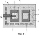
Figure 4 is a side view similar toFigure 1 and further illustrates an electronics device forming part of the electronics system; -
Figure 5 is cross-sectional side view on 5-5 inFigure 4 showing with to a close-up detailed view of the electronics device; -
Figure 6 is a cross-sectional side view of the electronics system further illustrating a calibration station; -
Figure 7 is a cross-sectional side view of the electronics system further illustrating the use of the calibration station to heat and calibrate the electronics device of the electronics system; -
Figure 8 is cross-sectional side view of the electronics system, further showing a field computer and a controlled system that uses calibration data; and -
Figure 9 is a cross-sectional side view of an electronics system according to another embodiment of the invention. - Output readings from movement detection devices, such as accelerometers and gyroscopes, can be affected by changes in temperature of the devices, thereby introducing temperature-dependent error in the output measurements. For example, an accelerometer at rest should provide an output measurement corresponding to gravitational acceleration; however when the accelerometer is subjected to different temperatures, the output measurement will be different due to error associated with the accelerometer being at a higher temperature. Because the output should not change while the accelerometer is at rest, that is, acceleration is still only gravity regardless of the temperature, it is possible to isolate the output measurement error associated with temperature by finding the difference (or "offset") between the erroneous measurement and the known baseline measurement (gravity in the case of an accelerometer). By conducting this measurement comparison at multiple temperatures, many data points are collected and an offset profile over a range of temperatures can be obtained. The collection of data associating temperatures with specific offset readings can be compiled for each movement detection device during the calibration process. The data can be stored as calibration data in a table for look up or extrapolation, or can be used to define a best fit function. The calibration data can be accessed by a virtual reality, augmented reality, or mixed reality system to obtain an adjusted measurement from a movement detection device given the temperature of the movement detection device and its initial "raw" measurement.
- A calibration system and process that improves calibration accuracy is described herein. Known methods of calibrating movement detection devices involve contacting the movement detection device with a thermal probe to introduce heat by conduction or require actively blowing air across the movement detection device to adjust its temperature by convection. Both of these methods can cause the device to move so that a measurement taken from the device during calibration will include an error associated with temperature and an error associated with movement introduced by the measurement method. Because it is not possible to know how much movement is introduced by the measurement method, it is not possible to isolate the error associated with temperature. As a result, the error cannot be accurately removed from the raw output measurement of the device. In virtual, augmented, and mixed reality systems, the accuracy of a measurement taken by a device is critical for determining where to display virtual content to a user with respect to movement between the user and the real or virtual environment. Thus, there exists a need for a highly accurate calibration system and method in a virtual, augmented, or mixed reality device.
-
Figures 1 ,2 and 3 illustrate anelectronics system 10, according to an embodiment of the disclosure.Figure 1 is a top view of an example configuration of aboard 12 in theelectronics system 10.Figure 2 is a cross-sectional side view on 2-2 inFigure 1 .Figure 3 is a cross-sectional side view on 3-3 inFigure 1 . Theelectronics system 10 includes aboard 12 made up of multiple layers of different materials. The layers and various features disposed therein provide particular functions during calibration and use of an electronics device 14 (discussed with respect toFigures 4 and5 ), such as a sensor or sensor suite, connected to theboard 12. - The
board 12 is constructed fromstructural material 22, such as FR4 dielectric, and a thermally and electrically conductive material, such asmetal components 24.Metal components 24 may include a copper material. The metal of themetal components 24 is more thermally conductive, and therefore has a higher thermal heat transfer capacity, than thestructural material 22. The metal of themetal components 24 is electrically conductive and thestructural material 22 is electrically insulating. - Multiple layers of
structural material 22 can be included in theboard 12. As shown in the example ofFigures 2 and 3 , twostructural layers metal components 24 are disposed between the layers ofstructural material 22. For example, themetal components 24 can include first, second andthird metal layers structural layers board 12 further includes top and bottominsulating layers third metal layers insulating layers material 25. - The
metal components 24 also include first and second sets ofvias vias 40 connects portions of thefirst metal layer 34 to portions of thesecond metal layer 36. The second set ofvias 42 connects portions of thesecond metal layer 36 to portions of thethird metal layer 38. Themetal layers metal layers vias first region 46 of the thermal conduit to asecond region 48 of the thermal conduit. - Portions of the
third metal layer 38 are isolated asmetal lines 76 to function as traces for electrical signals. Thesemetal lines 76 can be isolated from each other and fromother metal components 24 such that each line is surrounded by non-conductive material, such as dielectricstructural material 22 and insulating solder resistmaterial 25. One of skill in the art will appreciate that more or fewer than threemetal lines 76 may be provided depending on the design of theelectronic device 14 that is mounted to theboard 12 at thesecond region 48. The metal lines 76 may be disposed in one or more of the metal layers in theboard 12. Additionally, while thelines 76 are shown as exposed parts of themetal component 24, portions of themetal lines 76 can also be coated with the insulating solder resistmaterial 25. - The
metal components 24 further include athermal interface 52. Thethermal interface 52 is an area of thethird metal layer 38 at thefirst region 46 that has been exposed by removing a portion of the top insulatinglayer 32. Thethermal interface 52 is anupper surface 54 ofthird metal layer 38 that is exposed and is configured to contact part of an electronicdevice calibration station 80. Theupper surface 54 forms only a portion of an upper surface of theboard 12, with the remainder of the upper surface consisting of an upper surface of thestructural layer 30 and insulating solder resistlayer 32. - Referring to
Figures 1 and2 in combination, the first, second, and third metal layers 34, 36, 38 have aninner portion 58 and anouter portion 60. Thestructural material 22 forms a plurality ofbarriers 62 that distinguish theinner portion 58 from theouter portion 60. Thebarriers 62 act as thermal barriers to prevent heat from conducting from theinner portion 58 to theouter portion 60 of thesecond metal layer 36, or at least substantially slow the transfer of heat so that theouter portion 60 is kept cooler than theinner portion 58. Additional electronic components can be connected to theboard 12. Such components can be connected to theboard 12 at theouter portion 60 to keep the components from experiencing high heat during the calibration process. - Referring to
Figures 1 and3 in combination, it can be seen that the first, second, and third metal layers 34, 36, 38 also have connectingportions 64 that connect theinner portion 58 to theouter portion 60. The connectingportions 64 ensure that the metal layers are electrically grounded such that there is an equal reference voltage between theinner portion 58 and theouter portion 60. - Referring to
Figures 1 and2 in combination, it can be seen that similarthermal barriers 62 are formed at one or more positions within the first, second and third metal layers 34, 36 and 38 (Figure 1 ) and that each metal layer hasrespective portions 64 connecting inner and outer regions thereof. Thebarriers 62 prevent, or at least slow heat transfer from theinner portion 58 to theouter portion 60 to protect other components attached to theboard 12 from experiencing high temperatures during the calibration ofelectronics device 14. - Referring to
Figures 4 and5 , theelectronics system 10 further includes anelectronics device 14 and asystem storage 18. Theelectronics device 14 is mounted to an upper surface of theboard 12 throughconnections 74. Theelectronics device 14 and thethermal interface 52 are within thebarriers 62 that define theinner portion 58. Theelectronics device 14 is mounted above thesecond region 48 of the thermal conduit described above. - The
electronics system 10 further includes aboard interface 16 that is attached to theboard 12 and connected to the measurement devices in theelectronics device 14. Theelectronics device 14 includes astructural body 66 and a number measurement devices in thestructural body 66. The measurement devices include atemperature sensor 68 and two movement detection device in the form of anaccelerometer 70 and agyroscope 72. Although two movement detection devices are used for purposes of this embodiment, it may be possible to implement aspects of the invention using only one measurement device. It may for example be possible to calibrate an electronics device having only a gyroscope or only an accelerometer. Thestructural body 66 may, for example, be a silicon or other semiconductor structural body that may be packaged using conventional packaging technologies. Thetemperature sensor 68,accelerometer 70 andgyroscope 72 are connected throughconnectors 74 on an upper surface of theboard 12 andmetal lines 76 in theboard 12 to theboard interface 16. Data traces from thetemperature sensor 68,accelerometer 70, andgyroscope 72 are routed to amicroprocessor 73 in thestructural body 66 which serves as an input/output interface for the measurement devices. Thesystem storage 18 serves to store calibration data received from thecalibration station 80 that is associated with theaccelerometer 70 andgyroscope 72. Thesystem storage 18 may, for example, include a solid-state memory. Thesystem storage 18 is shown near theelectronics device 14, however, the system storage may be a remote storage, located on a cloud-based storage or on another area of the electronics device such that it is not in contact with theboard 12. One of skill in the art will appreciate that thesystem storage 18 may be located anywhere that is in communication withelectronics device 14 to allow for data transfer betweenelectronics device 14 andsystem storage 18. Thesystem storage 18 includes no calibration data immediately after theelectronics system 10 has been assembled (that is, prior to undergoing calibration) but is uniquely associated with theelectronics device 14 by enabling data to transfer between theelectronics device 14 and thesystem storage 18. -
Figure 6 further illustrates acalibration station 80 that is used to calibrate theaccelerometer 70 and thegyroscope 72. Thecalibration station 80 includes aframe 82, acalibration computer 84, acalibration computer interface 86, athermoelectric device 88, atransformer 90 and anelectric power connector 92. The components of thecalibration station 80 are mounted in a stationary position to one another via theframe 82. A spacing between thecalibration computer interface 86 and thethermoelectric device 88 is the same as a spacing between theboard interface 16 and thethermal interface 52. Thecalibration computer 84 is connected to thecalibration computer interface 86 so that signals can transmit between thecalibration computer 84 and thecalibration computer interface 86. Information from themicroprocessor 73 can be accessed by thecalibration station 80. Thecalibration computer 84 is connected to theelectric power connector 92 so that power can be provided through theelectric power connector 92 to thecalibration computer 84. Thethermoelectric device 88 is connected through thetransformer 90 to theelectric power connector 92. The power can be provided by theelectric power connector 92 through thetransformer 90 to thethermoelectric device 88. Thetransformer 90 reduces the voltage provided by theelectric power connector 92 before providing power to thethermoelectric device 88. Thethermoelectric device 88 is preferably a reversible heat pump, such as a thermoelectric cooler, capable of providing heat into theboard 12 or drawing heat out of theboard 12. The flexibility to achieve a wide range of temperatures on theboard 12, and thus at theelectronics device 14, can improve calibration accuracy of theelectronic device 14. - In use, the
electronics system 10 is brought into contact with portions of thecalibration station 80. When theelectronics system 10 and thecalibration station 80 move relatively towards one another, thecalibration computer interface 86 connects to theboard interface 16 and can begin receiving data from theelectronics device 14 at the same time that thethermoelectric device 88 comes into contact with thethermal interface 52. In the embodiment described, thecalibration computer interface 86 and theboard interface 16 are wired interfaces that come into contact with one another to create a communication link and are releasable from one another to break the communication link. Data is received through a wired communication between theelectronics system 10 and thecalibration station 80. In another embodiment, thecalibration station 80 and the board may include wireless interfaces that create a wireless link for data transfer and the wireless link sis then broken. - Electric power is provided through the
electric power connector 92 to thecalibration computer 84, which powers thecalibration computer 84. Electric power is also provided through theelectric power connector 92 and thetransformer 90 to thethermoelectric device 88. - The
entire electronics system 10 can begin calibration initially at room temperature, e.g. approximately 21°C. The temperature sensor 68 (Figure 5 ) provides an output of the temperature to thecalibration computer 84. Theaccelerometer 70 and thegyroscope 72 simultaneously provide outputs to thecalibration computer 84 that are associated with the output temperature from thetemperature sensor 68. Baseline outputs for the accelerometer and the gyroscope are either known because the device is at rest or are established at a reference temperature, such as at room temperature. These baseline outputs are used later in the calibration process to isolate errors in measurements ("offsets") that are associated with temperature changes of the sensors. -
Figure 7 illustrates that thecalibration computer 84 is connected to thesystem storage 18 andrecords calibration data 96 in thesystem storage 18 as the calibration offsets are calculated. A first entry in a table of thecalibration data 96 includes the initial temperature (in this example, 21°C), an acceleration offset (calculated by finding the difference between the acceleration measurement at temperature and the known acceleration), and an angle offset (calculated by finding the difference between the gyroscope measurement at temperature and the known positional information) that are calculated for a given temperature sensor measurement using inputs fromaccelerometer 70 andgyroscope 72, respectively. - The
thermoelectric device 88 has an upper surface that is at a lower temperature than room temperature and a lower surface that is at a higher temperature than room temperature. Heat transfers from the high temperature, lower surface of thethermoelectric device 88 through theupper surface 54 of thethermal interface 52 into thethermal interface 52. The heat transfer is primarily by way of conduction. The heat then conducts through thethird metal layer 38 and first and second sets ofvias first region 46 nearest the heat source outward toward thesecond region 48. Thebarriers 62 prevent or at least substantially retard transfer of heat from theinner portion 58 to theouter portion 60. - Heating of the
second region 48 causes its temperature to increase. Conduction of heat through the metal layers 34, 36, 38 and thethermal vias top metal layer 38 evenly distributes heat underneathelectronics device 14 in thesecond region 48. The increased temperature of thesecond region 48 causes heat transfer through conduction byconnection 74 and through passive convection of air surrounding theelectronics device 14. This method ofheating electronics device 14 closely mimics the field conditions that theelectronic device 14 will experience. Thetemperature sensor 68 continues to detect the temperature of theelectronics device 14. Thecalibration computer 84 samples the temperature of thetemperature sensor 68 on a predetermined interval, e.g. every five seconds, or more frequently for improved accuracy. Thecalibration computer 84 also samples outputs from theaccelerometer 70 and thegyroscope 72 at the same time that thecalibration computer 84 samples a temperature from thetemperature sensor 68. Thecalibration computer 84 then calculates and stores each temperature and each acceleration offset and each angle offset with thecalibration data 96. As described herein previously, each temperature is associated with an acceleration offset and an angle offset component within the measurement readings of the accelerometer and gyroscope, respectively. An offset profile can be obtained by measuring outputs of each sensor across a range of temperatures, each time subtracting the known value that the sensor should measure from the actual measurement to calculate error. Each temperature thus has a different acceleration offset and angle offset associated therewith, even though theaccelerometer 70 andgyroscope 72 remain stationary from one measurement to the next. In some embodiments, multiple measurements are obtained at each temperature and an average offset is calculated for improved accuracy. - When sufficient data is collected, the
calibration station 80 is removed from contact with theboard 12. Thecalibration computer interface 86 writes the collected calibration data to thesystem storage 18 and disconnects from theboard interface 16. Thethermoelectric device 88 disengages from thethermal interface 52. Heat convects and conducts from theelectronics device 14 until theentire electronics device 14 returns to room temperature. - The calibration system and process described above do not require physical contact between the calibration station and the
electronics device 14 and furthermore do not require forced convection acrosselectronics device 14. Rather, theelectronics device 14 is heated by way of conduction through a permanent connection (connectors 74 and metal lines 76) to theboard 12 and by way of passive convection without the need for additional probe contact with or forced air blowing over theelectronics device 14. Theelectronics device 14 can thus be calibrated against temperature without disturbing theaccelerometer 70 or thegyroscope 72. This system and process allows for a more accurate offset calibration while mimicking real field conditions of the sensors onboard electronics device 14. -
Figure 8 illustrates the electronics system in conjunction with afield computer 100, afield computer interface 102 and a controlledsystem 104. The controlledsystem 104 may be, for example, a virtual reality, augmented reality, or mixed reality device. Thefield computer 100 is connected to thefield computer interface 102. The controlledsystem 104 is connected to thefield computer 100. Thefield computer 100 may, for example, be a computer that processes movement data of an augmented reality viewing system and the controlledsystem 104 may be a vision processing system of the viewing device. Thefield computer 100 is connected to thesystem storage 18 and has access to thecalibration data 96. - In use, the
electronics system 10 is moved, e.g. in linear directions or rotational directions. Theaccelerometer 70 and thegyroscope 72 detect such movement of theelectronics system 10. Thefield computer 100 senses signals received from thetemperature sensor 68,accelerometer 70 andgyroscope 72. Thefield computer 100 uses the temperature detected by thetemperature sensor 68 to find a corresponding temperature in thecalibration data 96. Thecalibration data 96 may include the table with data as hereinbefore described or may include a formula, such as a linear regression, representative of the calibration data. Thefield computer 100 retrieves the acceleration offset and the angle offset in thecalibration data 96 corresponding to the temperature measured by thetemperature sensor 68. Thefield computer 100 then adjusts the acceleration detected by theaccelerometer 70 by the acceleration offset (acceleration = measured acceleration - acceleration offset). Thefield computer 100 also adjusts an angle measured by thegyroscope 72 by the angle offset corresponding to the temperature (adjusted angle = measured angle - angle offset). Thefield computer 100 then provides the adjusted acceleration and the adjusted angle to the controlledsystem 104. The controlledsystem 104 utilizes the adjusted acceleration and the adjusted angle in one or more formulas. By way of example, the controlledsystem 104 adjusts placement of a rendered image in an augmented reality or mixed reality viewing device according to a placement formula that uses the adjusted acceleration and the adjusted angle received from thefield computer 100. -
Figure 9 illustrates an alternate embodiment wherein a thermal conduit is provided by any known heat spreader that can be built into a chip. In some embodiments, the heat spreader can be aheat pipe 110. Theheat pipe 110 has anevaporator end 112 and acondenser end 114. Theevaporator end 112 is located against or in close proximity to thethermal interface 52 and thecondenser end 114 is located in close proximity to theelectronics device 14. In use, thethermal interface 52 heats a liquid in theheat pipe 110 and evaporates the liquid. The resultant vapor flows from theevaporator end 112 to thecondenser end 114 and condenses. The resulting condensed liquid then flows through a wicking system from thecondenser end 114 back to theevaporator end 112. -
Figures 1 to 8 illustrate one type of thermal conduit consisting of a thermally conductive metal. The design inFigures 1 to 8 is relatively inexpensive to manufacture.Figure 9 illustrates a different type of thermal conduit in the form of a heat pipe. A heat pipe may transfer more heat, through flow, than thermally conductive metal but may be more expensive to manufacture. The thermal conduit provided by the thermally conductive metal inFigures 1 to 8 and the thermal conduit provided by the heat pipe inFigure 9 both have a thermal heat transfer capacity that is higher than a thermal heat transfer capacity of thestructural material 22 of theboard 12 and both form a thermal path between the surface of thethermal interface 52 and theelectronics device 14. - The invention can also be directed to the following items: 1. An electronics system comprising: a board that includes: a structural material; a thermal conduit on the structural material, the thermal conduit having a thermal conductivity that is higher than a thermal conductivity of the structural material and having a first region, a second region, and a connecting portion connecting the first region to the second region; a thermal interface on the structural material, the thermal interface having a thermal heat transfer capacity that is higher than the thermal heat transfer capacity of the structural material and being attached to the first region of the thermal conduit; and an electronics device mounted to the board at the second region of the thermal conduit, the thermal conduit forming a thermal path between the surface of the thermal interface and the electronics device. 2. The electronics system of claim 1, wherein the thermal conduit includes a metal conductor. 3. The electronics system of
claim 2, wherein the thermal conduit includes at least two metal layers that are separated by a layer of the structural material. 4. The electronics system ofclaim 3, wherein the thermal conduit includes at least one metal via connecting the layers to one another. 5. The electronics system of claim 4, wherein the thermal conduit includes a plurality of metal vias connecting the layers to one another. 6. The electronics system ofclaim 2, wherein the metal conductor is made of a metal that is more thermally conductive than the structural material. 7. The electronics system ofclaim 2, wherein the board has at least one metal layer having an inner portion and an outer portion and the structural material forms a barrier between the inner portion and the outer portion, the inner portion forming the thermal conduit, and the thermal interface and the electronics device being located over the inner portion. 8. The electronics system ofclaim 7, wherein the metal layer is more electrically conductive than the structural material. 9. The electronics system ofclaim 7, wherein the structural material forms a plurality of barriers between the inner portion and the outer portion, wherein the barriers are alternated with portions of the metal layer that connect the inner portion to one another. 10. The electronics system of claim, 1, further comprising: a movement detection device in the electronics device; a system storage; and calibration data on the system storage, the calibration data including a first temperature of the movement detection device; a first output from the movement detection device recorded against the first temperature; and a second temperature of the movement detection device that is different than the first temperature; and a second output from the movement detection device recorded against the second temperature. 11. The electronics system ofclaim 10, wherein the movement detection device is an accelerometer. 12. The electronics system ofclaim 10, wherein the movement detection device is a gyroscope. 13. The electronics system ofclaim 10, further comprising: a temperature detector in the electronics device. 14. The electronics system ofclaim 13, further comprising: a field computer; an interface connecting the field computer to the movement detection device and the temperature detector; and a controlled system connected to the field computer. 15. A method of constructing an electronics system comprising: constructing a board including: forming a thermal conduit on the structural material, the thermal conduit having a thermal heat transfer capacity that is higher than a thermal heat transfer capacity of the structural material and having a first region, a second region, and a connecting portion connecting the first region to the second region; forming a thermal interface on the structural material, the thermal interface having a thermal heat transfer capacity conductivity that is higher than the thermal heat transfer capacity of the structural material and being attached to the first region of the thermal conduit; and mounting an electronics device to the board at the second region of the thermal conduit, the thermal conduit forming a thermal path between the surface of the thermal interface and the electronics device. 16. A method of operating an electronics device comprising: operating an electronics device mounted to a board; locating a thermal device adjacent a thermal interface of the board formed on a structural material of the board; and transferring heat between the thermal device and the electronics device through a thermal conduit on the structural material, the thermal conduit having a thermal heat transfer capacity that is higher than a thermal heat transfer capacity of the structural material and having a first region attached to the thermal interface, a second region at the electronics device, and a connecting portion connecting the first region to the second region. 17. The method ofclaim 16, further comprising: calibrating a movement detection device in the electronics device that detects movement while transferring the heat, the calibration of the device including: detecting a first temperature of the movement detection device; detecting a first output from the movement detection device; calculating a first offset based on the first output and a first baseline output; recording the first temperature and the first offset; changing a temperature of the movement detection device from the first temperature to a second temperature; detecting the second temperature of the movement detection device; detecting a second output from the movement detection device; calculating a second offset based on the second output and a second baseline output; and recording the second temperature and the second offset. 18. The method ofclaim 16, further comprising: removing the thermal device from the thermal interface after the calibration of the movement detection device. - While certain exemplary embodiments have been described and shown in the accompanying drawings, it is to be understood that such embodiments are merely illustrative and not restrictive of the current invention, and that this invention is not restricted to the specific constructions and arrangements shown and described since modifications may occur to those ordinarily skilled in the art.
Claims (13)
- An electronics system comprising:a board (12) that includes:a structural material (22);a thermal conduit on the structural material (22), the thermal conduit having a thermal conductivity that is higher than a thermal conductivity of the structural material and having a first region (46), a second region (48), and a connecting portion (40, 42) connecting the first region to the second region;a thermal interface (52) on the structural material (22), the thermal interface having a thermal heat transfer capacity that is higher than the thermal heat transfer capacity of the structural material (22) and being attached to the first region (38) of the thermal conduit;an electronics device (14) mounted to the board (12) at the second region (48) of the thermal conduit, the thermal conduit forming a thermal path between the surface of the thermal interface (52) and the electronics device (14); anda movement detection device (70, 72) in the electronics device (14);a system storage (18); andcalibration data on the system storage (18), the calibration data includinga first temperature of the movement detection device (70, 72);a first output from the movement detection device (70, 72) recorded against the first temperature; anda second temperature of the movement detection device (70, 72) that is different than the first temperature; anda second output from the movement detection device (70, 72) recorded against the second temperature.
- The electronics system of claim 1, wherein the thermal conduit includes a metal conductor.
- The electronics system of claim 2, wherein the thermal conduit includes at least two metal layers that are separated by a layer of the structural material (22).
- The electronics system of claim 3, wherein the thermal conduit includes at least one metal via connecting the layers to one another.
- The electronics system of claim 4, wherein the thermal conduit includes a plurality of metal vias (40, 42) connecting the layers to one another.
- The electronics system of any one of claims 2-5, wherein the metal conductor is made of a metal that is more thermally conductive than the structural material (22).
- The electronics system of any one of claims 2-6, wherein the board (12) has at least one metal layer having an inner portion and an outer portion and the structural material forms a barrier between the inner portion and the outer portion, the inner portion forming the thermal conduit, and the thermal interface and the electronics device being located over the inner portion.
- The electronics system of claim 7, wherein the metal layer is more electrically conductive than the structural material.
- The electronics system of claim 7 or 8, wherein the structural material forms a plurality of barriers between the inner portion and the outer portion, wherein the barriers are alternated with portions of the metal layer that connect the inner portion to one another.
- The electronics system of any one of claims 1-9, wherein the movement detection device is an accelerometer.
- The electronics system of any one of claims 1-10, wherein the movement detection device is a gyroscope.
- The electronics system of any one of claims 1-11, further comprising:
a temperature detector in the electronics device. - The electronics system of claim 12, further comprising:a field computer;an interface connecting the field computer to the movement detection device and the temperature detector; anda controlled system connected to the field computer.
Applications Claiming Priority (3)
| Application Number | Priority Date | Filing Date | Title |
|---|---|---|---|
| US201862702870P | 2018-07-24 | 2018-07-24 | |
| PCT/US2019/043099 WO2020023545A1 (en) | 2018-07-24 | 2019-07-23 | Temperature dependent calibration of movement detection devices |
| EP19839970.1A EP3827224B1 (en) | 2018-07-24 | 2019-07-23 | Temperature dependent calibration of movement detection devices |
Related Parent Applications (1)
| Application Number | Title | Priority Date | Filing Date |
|---|---|---|---|
| EP19839970.1A Division EP3827224B1 (en) | 2018-07-24 | 2019-07-23 | Temperature dependent calibration of movement detection devices |
Publications (3)
| Publication Number | Publication Date |
|---|---|
| EP4270016A2 true EP4270016A2 (en) | 2023-11-01 |
| EP4270016A3 EP4270016A3 (en) | 2024-02-07 |
| EP4270016B1 EP4270016B1 (en) | 2025-09-03 |
Family
ID=69180548
Family Applications (2)
| Application Number | Title | Priority Date | Filing Date |
|---|---|---|---|
| EP23195266.4A Active EP4270016B1 (en) | 2018-07-24 | 2019-07-23 | Temperature dependent calibration of movement detection devices |
| EP19839970.1A Active EP3827224B1 (en) | 2018-07-24 | 2019-07-23 | Temperature dependent calibration of movement detection devices |
Family Applications After (1)
| Application Number | Title | Priority Date | Filing Date |
|---|---|---|---|
| EP19839970.1A Active EP3827224B1 (en) | 2018-07-24 | 2019-07-23 | Temperature dependent calibration of movement detection devices |
Country Status (5)
| Country | Link |
|---|---|
| US (3) | US11598651B2 (en) |
| EP (2) | EP4270016B1 (en) |
| JP (3) | JP7426982B2 (en) |
| CN (2) | CN112689741B (en) |
| WO (1) | WO2020023545A1 (en) |
Families Citing this family (3)
| Publication number | Priority date | Publication date | Assignee | Title |
|---|---|---|---|---|
| CN111735488A (en) * | 2020-05-28 | 2020-10-02 | 黑龙江建筑职业技术学院 | Tool for measuring and calibrating environmental temperature and humidity equipment |
| CN115944123A (en) * | 2022-12-29 | 2023-04-11 | 深圳市基克纳科技有限公司 | Temperature calibration detection method, device, heat-not-burn smoking appliance and storage medium |
| CN117607495B (en) * | 2023-11-20 | 2024-09-13 | 中国航空工业集团公司北京长城计量测试技术研究所 | High-temperature rotating speed calibrating device |
Family Cites Families (603)
| Publication number | Priority date | Publication date | Assignee | Title |
|---|---|---|---|---|
| US6541736B1 (en) | 2001-12-10 | 2003-04-01 | Usun Technology Co., Ltd. | Circuit board/printed circuit board having pre-reserved conductive heating circuits |
| US4344092A (en) | 1980-10-21 | 1982-08-10 | Circon Corporation | Miniature video camera means for video system |
| US4652930A (en) | 1984-11-19 | 1987-03-24 | Rca Corporation | Television camera structure |
| US4810080A (en) | 1987-09-03 | 1989-03-07 | American Optical Corporation | Protective eyewear with removable nosepiece and corrective spectacle |
| US5142684A (en) | 1989-06-23 | 1992-08-25 | Hand Held Products, Inc. | Power conservation in microprocessor controlled devices |
| US4997268A (en) | 1989-07-24 | 1991-03-05 | Dauvergne Hector A | Corrective lens configuration |
| US5074295A (en) | 1989-08-03 | 1991-12-24 | Jamie, Inc. | Mouth-held holder |
| JPH0712944Y2 (en) * | 1989-08-24 | 1995-03-29 | 株式会社アドバンテスト | Electronic component mounting board temperature protection structure |
| US5007727A (en) | 1990-02-26 | 1991-04-16 | Alan Kahaney | Combination prescription lens and sunglasses assembly |
| US5396635A (en) | 1990-06-01 | 1995-03-07 | Vadem Corporation | Power conservation apparatus having multiple power reduction levels dependent upon the activity of the computer system |
| US5240220A (en) | 1990-09-12 | 1993-08-31 | Elbex Video Ltd. | TV camera supporting device |
| EP0504930B1 (en) | 1991-03-22 | 1998-06-10 | Nikon Corporation | Optical apparatus for correcting image deviation |
| WO1993001743A1 (en) | 1991-07-22 | 1993-02-04 | Adair Edwin Lloyd | Sterile video microscope holder for operating room |
| US5251635A (en) | 1991-09-03 | 1993-10-12 | General Electric Company | Stereoscopic X-ray fluoroscopy system using radiofrequency fields |
| US5224198A (en) | 1991-09-30 | 1993-06-29 | Motorola, Inc. | Waveguide virtual image display |
| CA2061117C (en) | 1991-12-02 | 1998-09-29 | Neta J. Amit | Apparatus and method for distributed program stack |
| US5497463A (en) | 1992-09-25 | 1996-03-05 | Bull Hn Information Systems Inc. | Ally mechanism for interconnecting non-distributed computing environment (DCE) and DCE systems to operate in a network system |
| US5937202A (en) | 1993-02-11 | 1999-08-10 | 3-D Computing, Inc. | High-speed, parallel, processor architecture for front-end electronics, based on a single type of ASIC, and method use thereof |
| US5410763A (en) | 1993-02-11 | 1995-05-02 | Etablissments Bolle | Eyeshield with detachable components |
| US5682255A (en) | 1993-02-26 | 1997-10-28 | Yeda Research & Development Co. Ltd. | Holographic optical devices for the transmission of optical signals of a plurality of channels |
| US6023288A (en) | 1993-03-31 | 2000-02-08 | Cairns & Brother Inc. | Combination head-protective helmet and thermal imaging apparatus |
| EP0632360A1 (en) | 1993-06-29 | 1995-01-04 | Xerox Corporation | Reducing computer power consumption by dynamic voltage and frequency variation |
| US5455625A (en) | 1993-09-23 | 1995-10-03 | Rosco Inc. | Video camera unit, protective enclosure and power circuit for same, particularly for use in vehicles |
| US5689669A (en) | 1994-04-29 | 1997-11-18 | General Magic | Graphical user interface for navigating between levels displaying hallway and room metaphors |
| US6016147A (en) | 1995-05-08 | 2000-01-18 | Autodesk, Inc. | Method and system for interactively determining and displaying geometric relationships between three dimensional objects based on predetermined geometric constraints and position of an input device |
| US5835061A (en) | 1995-06-06 | 1998-11-10 | Wayport, Inc. | Method and apparatus for geographic-based communications service |
| CA2180899A1 (en) | 1995-07-12 | 1997-01-13 | Yasuaki Honda | Synchronous updating of sub objects in a three dimensional virtual reality space sharing system and method therefore |
| US5826092A (en) | 1995-09-15 | 1998-10-20 | Gateway 2000, Inc. | Method and apparatus for performance optimization in power-managed computer systems |
| US5737533A (en) | 1995-10-26 | 1998-04-07 | Wegener Internet Projects Bv | System for generating a virtual reality scene in response to a database search |
| US6219045B1 (en) | 1995-11-13 | 2001-04-17 | Worlds, Inc. | Scalable virtual world chat client-server system |
| US5864365A (en) | 1996-01-26 | 1999-01-26 | Kaman Sciences Corporation | Environmentally controlled camera housing assembly |
| US6064749A (en) | 1996-08-02 | 2000-05-16 | Hirota; Gentaro | Hybrid tracking for augmented reality using both camera motion detection and landmark tracking |
| US5854872A (en) | 1996-10-08 | 1998-12-29 | Clio Technologies, Inc. | Divergent angle rotator system and method for collimating light beams |
| US8005254B2 (en) | 1996-11-12 | 2011-08-23 | Digimarc Corporation | Background watermark processing |
| US6012811A (en) | 1996-12-13 | 2000-01-11 | Contour Optik, Inc. | Eyeglass frames with magnets at bridges for attachment |
| JP3651204B2 (en) | 1996-12-18 | 2005-05-25 | トヨタ自動車株式会社 | Stereoscopic image display device, stereoscopic image display method, and recording medium |
| JP3465528B2 (en) | 1997-04-22 | 2003-11-10 | 三菱瓦斯化学株式会社 | New resin for optical materials |
| JPH10309381A (en) | 1997-05-13 | 1998-11-24 | Yoshimasa Tanaka | Amusement system for mobile object |
| US6271843B1 (en) | 1997-05-30 | 2001-08-07 | International Business Machines Corporation | Methods systems and computer program products for transporting users in three dimensional virtual reality worlds using transportation vehicles |
| EP1008959B1 (en) | 1997-08-29 | 2006-11-08 | Kabushiki Kaisha Sega doing business as Sega Corporation | Image processing system and image processing method |
| JPH11142783A (en) | 1997-11-12 | 1999-05-28 | Olympus Optical Co Ltd | Image display device |
| US6243091B1 (en) | 1997-11-21 | 2001-06-05 | International Business Machines Corporation | Global history view |
| US6385735B1 (en) | 1997-12-15 | 2002-05-07 | Intel Corporation | Method and apparatus for limiting processor clock frequency |
| US6079982A (en) | 1997-12-31 | 2000-06-27 | Meader; Gregory M | Interactive simulator ride |
| US6191809B1 (en) | 1998-01-15 | 2001-02-20 | Vista Medical Technologies, Inc. | Method and apparatus for aligning stereo images |
| US6362817B1 (en) | 1998-05-18 | 2002-03-26 | In3D Corporation | System for creating and viewing 3D environments using symbolic descriptors |
| US6076927A (en) | 1998-07-10 | 2000-06-20 | Owens; Raymond L. | Adjustable focal length eye glasses |
| US6119147A (en) | 1998-07-28 | 2000-09-12 | Fuji Xerox Co., Ltd. | Method and system for computer-mediated, multi-modal, asynchronous meetings in a virtual space |
| JP2000099332A (en) | 1998-09-25 | 2000-04-07 | Hitachi Ltd | Remote procedure call optimization method and program execution method using the same |
| US6414679B1 (en) | 1998-10-08 | 2002-07-02 | Cyberworld International Corporation | Architecture and methods for generating and displaying three dimensional representations |
| US6415388B1 (en) | 1998-10-30 | 2002-07-02 | Intel Corporation | Method and apparatus for power throttling in a microprocessor using a closed loop feedback system |
| US6918667B1 (en) | 1998-11-02 | 2005-07-19 | Gary Martin Zelman | Auxiliary eyewear attachment apparatus |
| US6487319B1 (en) | 1998-11-18 | 2002-11-26 | Sarnoff Corporation | Apparatus and method for identifying the location of a coding unit |
| US7111290B1 (en) | 1999-01-28 | 2006-09-19 | Ati International Srl | Profiling program execution to identify frequently-executed portions and to assist binary translation |
| US6556245B1 (en) | 1999-03-08 | 2003-04-29 | Larry Allan Holmberg | Game hunting video camera |
| US6396522B1 (en) | 1999-03-08 | 2002-05-28 | Dassault Systemes | Selection navigator |
| WO2000060444A1 (en) | 1999-04-06 | 2000-10-12 | Microsoft Corporation | Method and apparatus for supporting two-dimensional windows in a three-dimensional environment |
| US7119819B1 (en) | 1999-04-06 | 2006-10-10 | Microsoft Corporation | Method and apparatus for supporting two-dimensional windows in a three-dimensional environment |
| US6375369B1 (en) | 1999-04-22 | 2002-04-23 | Videolarm, Inc. | Housing for a surveillance camera |
| GB9930850D0 (en) | 1999-12-24 | 2000-02-16 | Koninkl Philips Electronics Nv | 3D environment labelling |
| US6621508B1 (en) | 2000-01-18 | 2003-09-16 | Seiko Epson Corporation | Information processing system |
| AU2001233019A1 (en) | 2000-01-28 | 2001-08-07 | Intersense, Inc. | Self-referenced tracking |
| JP4921634B2 (en) | 2000-01-31 | 2012-04-25 | グーグル インコーポレイテッド | Display device |
| US9129034B2 (en) | 2000-02-04 | 2015-09-08 | Browse3D Corporation | System and method for web browsing |
| KR20000030430A (en) | 2000-02-29 | 2000-06-05 | 김양신 | Internet advertisement system using virtual space based on 3 dimension graphic |
| JP2002015222A (en) | 2000-04-27 | 2002-01-18 | Nakajima Tsushinki Kogyo Kk | Web information providing system |
| JP4479051B2 (en) | 2000-04-28 | 2010-06-09 | ソニー株式会社 | Information processing apparatus and method, and recording medium |
| US6784901B1 (en) | 2000-05-09 | 2004-08-31 | There | Method, system and computer program product for the delivery of a chat message in a 3D multi-user environment |
| KR100487543B1 (en) | 2000-09-01 | 2005-05-03 | 엘지전자 주식회사 | Cpu scheduling method |
| US7788323B2 (en) | 2000-09-21 | 2010-08-31 | International Business Machines Corporation | Method and apparatus for sharing information in a virtual environment |
| JP4646374B2 (en) | 2000-09-29 | 2011-03-09 | オリンパス株式会社 | Image observation optical system |
| US7168051B2 (en) | 2000-10-10 | 2007-01-23 | Addnclick, Inc. | System and method to configure and provide a network-enabled three-dimensional computing environment |
| TW522256B (en) | 2000-12-15 | 2003-03-01 | Samsung Electronics Co Ltd | Wearable display system |
| US6715089B2 (en) | 2001-01-22 | 2004-03-30 | Ati International Srl | Reducing power consumption by estimating engine load and reducing engine clock speed |
| US20020108064A1 (en) | 2001-02-07 | 2002-08-08 | Patrick Nunally | System and method for optimizing power/performance in network-centric microprocessor-controlled devices |
| US6807352B2 (en) | 2001-02-11 | 2004-10-19 | Georgia Tech Research Corporation | Optical waveguides with embedded air-gap cladding layer and methods of fabrication thereof |
| US6931596B2 (en) | 2001-03-05 | 2005-08-16 | Koninklijke Philips Electronics N.V. | Automatic positioning of display depending upon the viewer's location |
| US7176942B2 (en) | 2001-03-23 | 2007-02-13 | Dassault Systemes | Collaborative design |
| US20020140848A1 (en) | 2001-03-30 | 2002-10-03 | Pelco | Controllable sealed chamber for surveillance camera |
| EP1249717A3 (en) | 2001-04-10 | 2005-05-11 | Matsushita Electric Industrial Co., Ltd. | Antireflection coating and optical element using the same |
| JPWO2002088913A1 (en) | 2001-04-27 | 2004-08-19 | インターナショナル・ビジネス・マシーンズ・コーポレーションInternational Business Maschines Corporation | Method and apparatus for controlling the operating speed of a processor |
| US6961055B2 (en) | 2001-05-09 | 2005-11-01 | Free Radical Design Limited | Methods and apparatus for constructing virtual environments |
| JP4682470B2 (en) | 2001-07-16 | 2011-05-11 | 株式会社デンソー | Scan type display device |
| US6622253B2 (en) | 2001-08-02 | 2003-09-16 | Scientific-Atlanta, Inc. | Controlling processor clock rate based on thread priority |
| US6762845B2 (en) | 2001-08-23 | 2004-07-13 | Zygo Corporation | Multiple-pass interferometry |
| WO2003027754A1 (en) | 2001-09-25 | 2003-04-03 | Cambridge Flat Projection Displays | Flat-panel projection display |
| US6833955B2 (en) | 2001-10-09 | 2004-12-21 | Planop Planar Optics Ltd. | Compact two-plane optical device |
| AU2002361572A1 (en) | 2001-10-19 | 2003-04-28 | University Of North Carolina At Chape Hill | Methods and systems for dynamic virtual convergence and head mountable display |
| JP3805231B2 (en) | 2001-10-26 | 2006-08-02 | キヤノン株式会社 | Image display apparatus and method, and storage medium |
| JP3834615B2 (en) | 2001-11-02 | 2006-10-18 | 独立行政法人産業技術総合研究所 | Image display method and system |
| US7076674B2 (en) | 2001-12-19 | 2006-07-11 | Hewlett-Packard Development Company L.P. | Portable computer having dual clock mode |
| JP2003329873A (en) | 2001-12-27 | 2003-11-19 | Fujikura Ltd | Optical fiber gripper with positioning mechanism, optical fiber adapter, and optical fiber processing device |
| US6592220B1 (en) | 2002-01-30 | 2003-07-15 | Lak Cheong | Eyeglass frame with removably mounted lenses |
| US7305020B2 (en) | 2002-02-04 | 2007-12-04 | Vizionware, Inc. | Method and system of reducing electromagnetic interference emissions |
| US7038694B1 (en) | 2002-03-11 | 2006-05-02 | Microsoft Corporation | Automatic scenery object generation |
| US6999087B2 (en) | 2002-03-12 | 2006-02-14 | Sun Microsystems, Inc. | Dynamically adjusting sample density in a graphics system |
| EP1351117A1 (en) | 2002-04-03 | 2003-10-08 | Hewlett-Packard Company | Data processing system and method |
| AU2003223746A1 (en) | 2002-04-25 | 2003-11-10 | Arc International | Apparatus and method for managing integrated circuit designs |
| US6849558B2 (en) | 2002-05-22 | 2005-02-01 | The Board Of Trustees Of The Leland Stanford Junior University | Replication and transfer of microstructures and nanostructures |
| KR100382232B1 (en) | 2002-05-31 | 2003-05-09 | Palm Palm Tech | Mobile terminal having enhanced power managing function and power managing method thereof |
| US7046515B1 (en) | 2002-06-06 | 2006-05-16 | Raytheon Company | Method and apparatus for cooling a circuit component |
| US7155617B2 (en) | 2002-08-01 | 2006-12-26 | Texas Instruments Incorporated | Methods and systems for performing dynamic power management via frequency and voltage scaling |
| US6714157B2 (en) | 2002-08-02 | 2004-03-30 | The Boeing Company | Multiple time-interleaved radar operation using a single radar at different angles |
| US20040113887A1 (en) | 2002-08-27 | 2004-06-17 | University Of Southern California | partially real and partially simulated modular interactive environment |
| KR100480786B1 (en) | 2002-09-02 | 2005-04-07 | 삼성전자주식회사 | Integrated type optical head with coupler |
| AU2003265891A1 (en) | 2002-09-04 | 2004-03-29 | Mentor Graphics (Holdings) Ltd. | Polymorphic computational system and method in signals intelligence analysis |
| US8458028B2 (en) | 2002-10-16 | 2013-06-04 | Barbaro Technologies | System and method for integrating business-related content into an electronic game |
| AU2003283680A1 (en) | 2002-12-04 | 2004-06-23 | Koninklijke Philips Electronics N.V. | Software-based control of microprocessor power dissipation |
| US7306337B2 (en) | 2003-03-06 | 2007-12-11 | Rensselaer Polytechnic Institute | Calibration-free gaze tracking under natural head movement |
| US20050128212A1 (en) | 2003-03-06 | 2005-06-16 | Edecker Ada M. | System and method for minimizing the amount of data necessary to create a virtual three-dimensional environment |
| DE10311972A1 (en) | 2003-03-18 | 2004-09-30 | Carl Zeiss | Head-mounted display (HMD) apparatus for use with eyeglasses, has optical projector that is fastened to rack, and under which eyeglasses are positioned when rack and eyeglasses are attached together |
| AU2003901272A0 (en) | 2003-03-19 | 2003-04-03 | Martin Hogan Pty Ltd | Improvements in or relating to eyewear attachments |
| US7294360B2 (en) | 2003-03-31 | 2007-11-13 | Planar Systems, Inc. | Conformal coatings for micro-optical elements, and method for making the same |
| US20040205757A1 (en) | 2003-04-09 | 2004-10-14 | Pering Trevor A. | Performance scheduling using multiple constraints |
| CN100416340C (en) | 2003-04-25 | 2008-09-03 | 微型光学公司 | binocular viewing system |
| EP1639394A2 (en) | 2003-06-10 | 2006-03-29 | Elop Electro-Optics Industries Ltd. | Method and system for displaying an informative image against a background image |
| US20040268159A1 (en) | 2003-06-30 | 2004-12-30 | Microsoft Corporation | Power profiling |
| US7467356B2 (en) | 2003-07-25 | 2008-12-16 | Three-B International Limited | Graphical user interface for 3d virtual display browser using virtual display windows |
| US7134031B2 (en) | 2003-08-04 | 2006-11-07 | Arm Limited | Performance control within a multi-processor system |
| JP3931336B2 (en) | 2003-09-26 | 2007-06-13 | マツダ株式会社 | Vehicle information providing device |
| JP2005151224A (en) | 2003-11-17 | 2005-06-09 | Ntt Docomo Inc | Content transmitting apparatus and communication system |
| US7434083B1 (en) | 2004-01-06 | 2008-10-07 | Apple Inc. | Method and apparatus for the generation and control of clock signals |
| JP4699699B2 (en) | 2004-01-15 | 2011-06-15 | 株式会社東芝 | Beam light scanning apparatus and image forming apparatus |
| US7269590B2 (en) | 2004-01-29 | 2007-09-11 | Yahoo! Inc. | Method and system for customizing views of information associated with a social network user |
| US7418170B2 (en) | 2004-03-29 | 2008-08-26 | Sony Corporation | Optical device and virtual image display device |
| JP4364047B2 (en) | 2004-04-14 | 2009-11-11 | オリンパス株式会社 | Display device, imaging device |
| CN100350792C (en) | 2004-04-14 | 2007-11-21 | 奥林巴斯株式会社 | Image capturing apparatus |
| US7219245B1 (en) | 2004-06-03 | 2007-05-15 | Advanced Micro Devices, Inc. | Adaptive CPU clock management |
| US20060019723A1 (en) | 2004-06-29 | 2006-01-26 | Pieter Vorenkamp | Automatic control of power save operation in a portable communication device utilizing historical usage information |
| US7382288B1 (en) | 2004-06-30 | 2008-06-03 | Rockwell Collins, Inc. | Display of airport signs on head-up display |
| US7211986B1 (en) | 2004-07-01 | 2007-05-01 | Plantronics, Inc. | Inductive charging system |
| GB0416038D0 (en) | 2004-07-16 | 2004-08-18 | Portland Press Ltd | Document display system |
| EP1769275A1 (en) | 2004-07-22 | 2007-04-04 | Pirelli & C. S.p.A. | Integrated wavelength selective grating-based filter |
| US7542040B2 (en) | 2004-08-11 | 2009-06-02 | The United States Of America As Represented By The Secretary Of The Navy | Simulated locomotion method and apparatus |
| WO2006016366A2 (en) | 2004-08-12 | 2006-02-16 | Elop Electro-Optical Industries Ltd. | Integrated retinal imager and method |
| US9030532B2 (en) | 2004-08-19 | 2015-05-12 | Microsoft Technology Licensing, Llc | Stereoscopic image display |
| US7029114B2 (en) | 2004-09-03 | 2006-04-18 | E'lite Optik U.S. L.P. | Eyewear assembly with auxiliary frame and lens assembly |
| EP2990839B1 (en) | 2004-09-16 | 2020-11-18 | Nikon Corporation | Optical system with mgf2 optical thin film |
| US20060090092A1 (en) | 2004-10-25 | 2006-04-27 | Verhulst Anton H | Clock timing adjustment |
| US7536567B2 (en) | 2004-12-10 | 2009-05-19 | Hewlett-Packard Development Company, L.P. | BIOS-based systems and methods of processor power management |
| US20060126181A1 (en) | 2004-12-13 | 2006-06-15 | Nokia Corporation | Method and system for beam expansion in a display device |
| US8619365B2 (en) | 2004-12-29 | 2013-12-31 | Corning Incorporated | Anti-reflective coating for optical windows and elements |
| GB0502453D0 (en) | 2005-02-05 | 2005-03-16 | Cambridge Flat Projection | Flat panel lens |
| US7573640B2 (en) | 2005-04-04 | 2009-08-11 | Mirage Innovations Ltd. | Multi-plane optical apparatus |
| US20060250322A1 (en) | 2005-05-09 | 2006-11-09 | Optics 1, Inc. | Dynamic vergence and focus control for head-mounted displays |
| US7948683B2 (en) | 2006-05-14 | 2011-05-24 | Holochip Corporation | Fluidic lens with manually-adjustable focus |
| US7644148B2 (en) | 2005-05-16 | 2010-01-05 | Hewlett-Packard Development Company, L.P. | Historical data based workload allocation |
| CN101228483B (en) | 2005-06-03 | 2010-05-26 | 诺基亚公司 | A Universal Diffractive Optics Method for Expanding the Exit Pupil |
| US7364306B2 (en) | 2005-06-20 | 2008-04-29 | Digital Display Innovations, Llc | Field sequential light source modulation for a digital display system |
| US10198521B2 (en) | 2005-06-27 | 2019-02-05 | Google Llc | Processing ambiguous search requests in a geographic information system |
| JP4776285B2 (en) | 2005-07-01 | 2011-09-21 | ソニー株式会社 | Illumination optical device and virtual image display device using the same |
| JP4763439B2 (en) | 2005-08-08 | 2011-08-31 | オリンパス株式会社 | Medical device magnetic guidance and position detection system |
| JP4660787B2 (en) | 2005-08-25 | 2011-03-30 | 隆広 西岡 | glasses |
| US7739524B2 (en) | 2005-08-29 | 2010-06-15 | The Invention Science Fund I, Inc | Power consumption management |
| US20070058248A1 (en) | 2005-09-14 | 2007-03-15 | Nguyen Minh T | Sport view binocular-zoom lens focus system |
| US20080043334A1 (en) | 2006-08-18 | 2008-02-21 | Mirage Innovations Ltd. | Diffractive optical relay and method for manufacturing the same |
| US7869128B2 (en) | 2005-09-27 | 2011-01-11 | Konica Minolta Holdings, Inc. | Head mounted display |
| EP1938141A1 (en) | 2005-09-28 | 2008-07-02 | Mirage Innovations Ltd. | Stereoscopic binocular system, device and method |
| US7817150B2 (en) | 2005-09-30 | 2010-10-19 | Rockwell Automation Technologies, Inc. | Three-dimensional immersive system for representing an automation control environment |
| US7835785B2 (en) | 2005-10-04 | 2010-11-16 | Ascension Technology Corporation | DC magnetic-based position and orientation monitoring system for tracking medical instruments |
| US11428937B2 (en) | 2005-10-07 | 2022-08-30 | Percept Technologies | Enhanced optical and perceptual digital eyewear |
| US20070081123A1 (en) | 2005-10-07 | 2007-04-12 | Lewis Scott W | Digital eyewear |
| US9658473B2 (en) | 2005-10-07 | 2017-05-23 | Percept Technologies Inc | Enhanced optical and perceptual digital eyewear |
| US8696113B2 (en) | 2005-10-07 | 2014-04-15 | Percept Technologies Inc. | Enhanced optical and perceptual digital eyewear |
| KR101193331B1 (en) | 2005-10-14 | 2012-10-19 | 엘지전자 주식회사 | Power Consumption Management System and Method in the Graphic Apparatus |
| US20090128902A1 (en) | 2005-11-03 | 2009-05-21 | Yehuda Niv | Binocular Optical Relay Device |
| EP1949147B1 (en) | 2005-11-18 | 2012-03-21 | Nanocomp Oy Ltd. | Method of producing a diffraction grating element |
| US20070171328A1 (en) | 2005-11-21 | 2007-07-26 | Freeman Mark O | Substrate-guided display |
| US7917573B2 (en) | 2005-11-30 | 2011-03-29 | International Business Machines Corporation | Measuring and reporting processor capacity and processor usage in a computer system with processors of different speed and/or architecture |
| JP2007199841A (en) | 2006-01-24 | 2007-08-09 | Seiko Epson Corp | Electronic device controller, bus control device |
| WO2007085682A1 (en) | 2006-01-26 | 2007-08-02 | Nokia Corporation | Eye tracker device |
| KR20060059992A (en) | 2006-01-31 | 2006-06-02 | 닛토덴코 가부시키가이샤 | Interference optical filter |
| JP2007219106A (en) | 2006-02-16 | 2007-08-30 | Konica Minolta Holdings Inc | Optical device for expanding diameter of luminous flux, video display device and head mount display |
| US7461535B2 (en) * | 2006-03-01 | 2008-12-09 | Memsic, Inc. | Multi-temperature programming for accelerometer |
| IL174170A (en) | 2006-03-08 | 2015-02-26 | Abraham Aharoni | Device and method for binocular alignment |
| US7353134B2 (en) | 2006-03-09 | 2008-04-01 | Dean A. Cirielli | Three-dimensional position and motion telemetry input |
| CN101449270B (en) | 2006-03-15 | 2011-11-16 | 谷歌公司 | Automatic display of resized images |
| JP2007273733A (en) | 2006-03-31 | 2007-10-18 | Tdk Corp | Manufacturing method of solid state electrolytic capacitor |
| WO2007141587A1 (en) | 2006-06-02 | 2007-12-13 | Nokia Corporation | Color distribution in exit pupil expanders |
| EP1868149B1 (en) | 2006-06-14 | 2019-08-07 | Dassault Systèmes | Improved computerized collaborative work |
| US7692855B2 (en) | 2006-06-28 | 2010-04-06 | Essilor International Compagnie Generale D'optique | Optical article having a temperature-resistant anti-reflection coating with optimized thickness ratio of low index and high index layers |
| US9015501B2 (en) | 2006-07-13 | 2015-04-21 | International Business Machines Corporation | Structure for asymmetrical performance multi-processors |
| US7724980B1 (en) | 2006-07-24 | 2010-05-25 | Adobe Systems Incorporated | System and method for selective sharpening of images |
| US8214660B2 (en) | 2006-07-26 | 2012-07-03 | International Business Machines Corporation | Structure for an apparatus for monitoring and controlling heat generation in a multi-core processor |
| KR100809479B1 (en) | 2006-07-27 | 2008-03-03 | 한국전자통신연구원 | Face Wearable Display Devices for Mixed Reality Environments |
| US20080030429A1 (en) | 2006-08-07 | 2008-02-07 | International Business Machines Corporation | System and method of enhanced virtual reality |
| US7640449B2 (en) | 2006-08-17 | 2009-12-29 | Via Technologies, Inc. | Systems and methods for dynamic clock frequencies for low power design |
| US9582060B2 (en) | 2006-08-31 | 2017-02-28 | Advanced Silicon Technologies Llc | Battery-powered device with reduced power consumption based on an application profile data |
| JP4861105B2 (en) | 2006-09-15 | 2012-01-25 | 株式会社エヌ・ティ・ティ・ドコモ | Spatial bulletin board system |
| US20080125218A1 (en) | 2006-09-20 | 2008-05-29 | Kelly James Collins | Method of use for a commercially available portable virtual reality system |
| US20080068557A1 (en) | 2006-09-20 | 2008-03-20 | Gilbert Menduni | Lens holding frame |
| CN101512413B (en) | 2006-09-28 | 2012-02-15 | 诺基亚公司 | Beam spread using three-dimensional diffraction element |
| US20090300528A1 (en) | 2006-09-29 | 2009-12-03 | Stambaugh Thomas M | Browser event tracking for distributed web-based processing, spatial organization and display of information |
| CN105445835B (en) | 2006-10-31 | 2021-07-27 | 莫迪里斯控股有限责任公司 | Lighting device and lighting system |
| US20080146942A1 (en) | 2006-12-13 | 2008-06-19 | Ep Medsystems, Inc. | Catheter Position Tracking Methods Using Fluoroscopy and Rotational Sensors |
| WO2008071830A1 (en) | 2006-12-14 | 2008-06-19 | Nokia Corporation | Display device having two operating modes |
| JP4847351B2 (en) | 2007-01-11 | 2011-12-28 | キヤノン株式会社 | Diffractive optical element and diffraction grating using the same |
| US7418368B2 (en) | 2007-01-18 | 2008-08-26 | International Business Machines Corporation | Method and system for testing processor cores |
| JP4348441B2 (en) | 2007-01-22 | 2009-10-21 | 国立大学法人 大阪教育大学 | Position detection apparatus, position detection method, data determination apparatus, data determination method, computer program, and storage medium |
| US8726681B2 (en) | 2007-01-23 | 2014-05-20 | Hewlett-Packard Development Company, L.P. | Method and system of cooling components of a computer system |
| US8374673B2 (en) | 2007-01-25 | 2013-02-12 | Warsaw Orthopedic, Inc. | Integrated surgical navigational and neuromonitoring system having automated surgical assistance and control |
| US20090017910A1 (en) | 2007-06-22 | 2009-01-15 | Broadcom Corporation | Position and motion tracking of an object |
| JP2010146030A (en) | 2007-03-29 | 2010-07-01 | Access Co Ltd | Search system, portable information device, and search program |
| JP5194530B2 (en) | 2007-04-09 | 2013-05-08 | 凸版印刷株式会社 | Image display device and image display method |
| US7733439B2 (en) | 2007-04-30 | 2010-06-08 | Qualcomm Mems Technologies, Inc. | Dual film light guide for illuminating displays |
| EP3667399A1 (en) | 2007-06-04 | 2020-06-17 | Magic Leap, Inc. | A diffractive beam expander |
| US8060759B1 (en) | 2007-06-29 | 2011-11-15 | Emc Corporation | System and method of managing and optimizing power consumption in a storage system |
| US9387402B2 (en) | 2007-09-18 | 2016-07-12 | Disney Enterprises, Inc. | Method and system for converting a computer virtual environment into a real-life simulation environment |
| JP2009090689A (en) | 2007-10-03 | 2009-04-30 | Calsonic Kansei Corp | Head-up display |
| US8368721B2 (en) | 2007-10-06 | 2013-02-05 | Mccoy Anthony | Apparatus and method for on-field virtual reality simulation of US football and other sports |
| US7844724B2 (en) | 2007-10-24 | 2010-11-30 | Social Communications Company | Automated real-time data stream switching in a shared virtual area communication environment |
| US9147213B2 (en) | 2007-10-26 | 2015-09-29 | Zazzle Inc. | Visualizing a custom product in situ |
| US20110041083A1 (en) | 2007-12-12 | 2011-02-17 | Oz Gabai | System and methodology for providing shared internet experience |
| US8508848B2 (en) | 2007-12-18 | 2013-08-13 | Nokia Corporation | Exit pupil expanders with wide field-of-view |
| DE102008005817A1 (en) | 2008-01-24 | 2009-07-30 | Carl Zeiss Ag | Optical display device |
| CN101945612B (en) | 2008-02-14 | 2013-09-25 | 诺基亚公司 | Device and method for determining gaze direction |
| JP2009244869A (en) | 2008-03-11 | 2009-10-22 | Panasonic Corp | Display apparatus, display method, goggle-type head-mounted display, and vehicle |
| US7650253B2 (en) * | 2008-05-08 | 2010-01-19 | L-3 Communications Corporation | Accelerometer and method for error compensation |
| US8296196B2 (en) | 2008-05-15 | 2012-10-23 | International Business Machines Corporation | Tag along shopping |
| US9400212B2 (en) | 2008-06-13 | 2016-07-26 | Barco Inc. | Smart pixel addressing |
| JP5181860B2 (en) | 2008-06-17 | 2013-04-10 | セイコーエプソン株式会社 | Pulse width modulation signal generation apparatus, image display apparatus including the same, and pulse width modulation signal generation method |
| JP5027746B2 (en) | 2008-07-01 | 2012-09-19 | 株式会社トプコン | POSITION MEASUREMENT METHOD, POSITION MEASUREMENT DEVICE, AND PROGRAM |
| US8250389B2 (en) | 2008-07-03 | 2012-08-21 | International Business Machines Corporation | Profiling an application for power consumption during execution on a plurality of compute nodes |
| US10885471B2 (en) | 2008-07-18 | 2021-01-05 | Disney Enterprises, Inc. | System and method for providing location-based data on a wireless portable device |
| GB2462589B (en) | 2008-08-04 | 2013-02-20 | Sony Comp Entertainment Europe | Apparatus and method of viewing electronic documents |
| US7850306B2 (en) | 2008-08-28 | 2010-12-14 | Nokia Corporation | Visual cognition aware display and visual data transmission architecture |
| US8149493B2 (en) | 2008-09-06 | 2012-04-03 | Sifotonics Technologies (Usa) Inc. | Electro-optic silicon modulator |
| US8229800B2 (en) | 2008-09-13 | 2012-07-24 | At&T Intellectual Property I, L.P. | System and method for an enhanced shopping experience |
| US7885506B2 (en) | 2008-09-26 | 2011-02-08 | Nokia Corporation | Device and a method for polarized illumination of a micro-display |
| EP2350774A4 (en) | 2008-10-14 | 2014-11-05 | Oblong Ind Inc | MULTI-PROCESS INTERACTIVE SYSTEMS AND METHODS |
| EP2348982B1 (en) | 2008-12-03 | 2020-03-25 | St. Jude Medical, Atrial Fibrillation Division, Inc. | System for determining the positioin of the tip of a medical catheter within the body of a patient |
| JP2010139575A (en) | 2008-12-09 | 2010-06-24 | Brother Ind Ltd | See-through type head-mounted display device |
| US20100153934A1 (en) | 2008-12-12 | 2010-06-17 | Peter Lachner | Prefetch for systems with heterogeneous architectures |
| US8325088B2 (en) | 2009-02-04 | 2012-12-04 | Google Inc. | Mobile device battery management |
| US8539359B2 (en) | 2009-02-11 | 2013-09-17 | Jeffrey A. Rapaport | Social network driven indexing system for instantly clustering people with concurrent focus on same topic into on-topic chat rooms and/or for generating on-topic search results tailored to user preferences regarding topic |
| US8411086B2 (en) | 2009-02-24 | 2013-04-02 | Fuji Xerox Co., Ltd. | Model creation using visual markup languages |
| US8699141B2 (en) | 2009-03-13 | 2014-04-15 | Knowles Electronics, Llc | Lens assembly apparatus and method |
| JP5121764B2 (en) | 2009-03-24 | 2013-01-16 | 株式会社東芝 | Solid-state imaging device |
| US9095436B2 (en) | 2009-04-14 | 2015-08-04 | The Invention Science Fund I, Llc | Adjustable orthopedic implant and method for treating an orthopedic condition in a subject |
| US20100274567A1 (en) | 2009-04-22 | 2010-10-28 | Mark Carlson | Announcing information about payment transactions of any member of a consumer group |
| US20100274627A1 (en) | 2009-04-22 | 2010-10-28 | Mark Carlson | Receiving an announcement triggered by location data |
| US8839121B2 (en) | 2009-05-06 | 2014-09-16 | Joseph Bertolami | Systems and methods for unifying coordinate systems in augmented reality applications |
| US9383823B2 (en) | 2009-05-29 | 2016-07-05 | Microsoft Technology Licensing, Llc | Combining gestures beyond skeletal |
| US20110010636A1 (en) | 2009-07-13 | 2011-01-13 | International Business Machines Corporation | Specification of a characteristic of a virtual universe establishment |
| KR20110006408A (en) | 2009-07-14 | 2011-01-20 | 권소망 | Joining method of eyeglasses and clips, and the joining structure |
| US20110022870A1 (en) | 2009-07-21 | 2011-01-27 | Microsoft Corporation | Component power monitoring and workload optimization |
| US8758125B2 (en) | 2009-07-24 | 2014-06-24 | Wms Gaming, Inc. | Controlling event-driven behavior of wagering game objects |
| JP2011033993A (en) | 2009-08-05 | 2011-02-17 | Sharp Corp | Information presenting apparatus and method for presenting information |
| JP5316391B2 (en) | 2009-08-31 | 2013-10-16 | ソニー株式会社 | Image display device and head-mounted display |
| US8738949B2 (en) | 2009-08-31 | 2014-05-27 | Empire Technology Development Llc | Power management for processor |
| US20110050640A1 (en) | 2009-09-03 | 2011-03-03 | Niklas Lundback | Calibration for a Large Scale Multi-User, Multi-Touch System |
| US8170283B2 (en) | 2009-09-17 | 2012-05-01 | Behavioral Recognition Systems Inc. | Video surveillance system configured to analyze complex behaviors using alternating layers of clustering and sequencing |
| US11320571B2 (en) | 2012-11-16 | 2022-05-03 | Rockwell Collins, Inc. | Transparent waveguide display providing upper and lower fields of view with uniform light extraction |
| CN102741828B (en) | 2009-10-30 | 2015-12-09 | 英特尔公司 | Bi-directional communication support for heterogeneous processors of computer platforms |
| US8305502B2 (en) | 2009-11-11 | 2012-11-06 | Eastman Kodak Company | Phase-compensated thin-film beam combiner |
| US8605209B2 (en) | 2009-11-24 | 2013-12-10 | Gregory Towle Becker | Hurricane damage recording camera system |
| JP2011118837A (en) | 2009-12-07 | 2011-06-16 | Sony Corp | Information processing device, information processing method and program |
| US8909962B2 (en) | 2009-12-16 | 2014-12-09 | Qualcomm Incorporated | System and method for controlling central processing unit power with guaranteed transient deadlines |
| US9244533B2 (en) | 2009-12-17 | 2016-01-26 | Microsoft Technology Licensing, Llc | Camera navigation for presentations |
| US8751854B2 (en) | 2009-12-21 | 2014-06-10 | Empire Technology Development Llc | Processor core clock rate selection |
| US8565554B2 (en) | 2010-01-09 | 2013-10-22 | Microsoft Corporation | Resizing of digital images |
| KR101099137B1 (en) | 2010-01-29 | 2011-12-27 | 주식회사 팬택 | Method and Apparatus for Providing Augmented Reality Information in Mobile Communication System |
| US8549339B2 (en) | 2010-02-26 | 2013-10-01 | Empire Technology Development Llc | Processor core communication in multi-core processor |
| US8467133B2 (en) | 2010-02-28 | 2013-06-18 | Osterhout Group, Inc. | See-through display with an optical assembly including a wedge-shaped illumination system |
| US11275482B2 (en) | 2010-02-28 | 2022-03-15 | Microsoft Technology Licensing, Llc | Ar glasses with predictive control of external device based on event input |
| US9547910B2 (en) | 2010-03-04 | 2017-01-17 | Honeywell International Inc. | Method and apparatus for vision aided navigation using image registration |
| WO2011107831A1 (en) | 2010-03-04 | 2011-09-09 | Nokia Corporation | Optical apparatus and method for expanding an exit pupil |
| JP5499854B2 (en) | 2010-04-08 | 2014-05-21 | ソニー株式会社 | Optical position adjustment method for head mounted display |
| US8118499B2 (en) | 2010-05-19 | 2012-02-21 | LIR Systems, Inc. | Infrared camera assembly systems and methods |
| US20110291964A1 (en) | 2010-06-01 | 2011-12-01 | Kno, Inc. | Apparatus and Method for Gesture Control of a Dual Panel Electronic Device |
| JP5923696B2 (en) * | 2010-06-08 | 2016-05-25 | アキム株式会社 | Table device for angular velocity sensor inspection |
| JP2012015774A (en) | 2010-06-30 | 2012-01-19 | Toshiba Corp | Stereoscopic image processing device and stereoscopic image imaging method |
| US8560876B2 (en) | 2010-07-06 | 2013-10-15 | Sap Ag | Clock acceleration of CPU core based on scanned result of task for parallel execution controlling key word |
| US8601288B2 (en) | 2010-08-31 | 2013-12-03 | Sonics, Inc. | Intelligent power controller |
| US8854594B2 (en) | 2010-08-31 | 2014-10-07 | Cast Group Of Companies Inc. | System and method for tracking |
| KR101479262B1 (en) | 2010-09-02 | 2015-01-12 | 주식회사 팬택 | Method and apparatus for authorizing use of augmented reality information |
| US8949808B2 (en) | 2010-09-23 | 2015-02-03 | Apple Inc. | Systems and methods for compiler-based full-function vectorization |
| JP5632693B2 (en) | 2010-09-28 | 2014-11-26 | 任天堂株式会社 | Information processing program, information processing apparatus, information processing method, and information processing system |
| US20120081392A1 (en) | 2010-09-30 | 2012-04-05 | Apple Inc. | Electronic device operation adjustment based on face detection |
| US8688926B2 (en) | 2010-10-10 | 2014-04-01 | Liqid Inc. | Systems and methods for optimizing data storage among a plurality of solid state memory subsystems |
| KR101260576B1 (en) | 2010-10-13 | 2013-05-06 | 주식회사 팬택 | User Equipment and Method for providing AR service |
| JP5939733B2 (en) | 2010-10-15 | 2016-06-22 | 任天堂株式会社 | Image processing program, image processing apparatus, image processing system, and image processing method |
| JP2014500522A (en) | 2010-10-26 | 2014-01-09 | オプトチューン アクチエンゲゼルシャフト | Variable focus lens with two liquid chambers |
| US9406166B2 (en) | 2010-11-08 | 2016-08-02 | Seereal Technologies S.A. | Display device, in particular a head-mounted display, based on temporal and spatial multiplexing of hologram tiles |
| US20120113235A1 (en) | 2010-11-08 | 2012-05-10 | Sony Corporation | 3d glasses, systems, and methods for optimized viewing of 3d video content |
| JP5854593B2 (en) | 2010-11-17 | 2016-02-09 | キヤノン株式会社 | Multilayer diffractive optical element |
| US9304319B2 (en) | 2010-11-18 | 2016-04-05 | Microsoft Technology Licensing, Llc | Automatic focus improvement for augmented reality displays |
| US9213405B2 (en) | 2010-12-16 | 2015-12-15 | Microsoft Technology Licensing, Llc | Comprehension and intent-based content for augmented reality displays |
| KR101263481B1 (en) * | 2011-01-14 | 2013-05-13 | 주식회사 유비트로닉스 | Temperature compensation method of sensor, and sensor including temperature compensating function |
| US10391277B2 (en) | 2011-02-18 | 2019-08-27 | Voxel Rad, Ltd. | Systems and methods for 3D stereoscopic angiovision, angionavigation and angiotherapeutics |
| US20160187654A1 (en) | 2011-02-28 | 2016-06-30 | Microsoft Technology Licensing, Llc | See-through near-eye display glasses with a light transmissive wedge shaped illumination system |
| CN102163584A (en) * | 2011-03-14 | 2011-08-24 | 苏州佳世达电通有限公司 | Electronic device |
| WO2012125172A1 (en) * | 2011-03-15 | 2012-09-20 | Kona Medical, Inc. | Energetic modulation of nerves |
| US8949637B2 (en) | 2011-03-24 | 2015-02-03 | Intel Corporation | Obtaining power profile information with low overhead |
| US9142062B2 (en) | 2011-03-29 | 2015-09-22 | Qualcomm Incorporated | Selective hand occlusion over virtual projections onto physical surfaces using skeletal tracking |
| KR101210163B1 (en) | 2011-04-05 | 2012-12-07 | 엘지이노텍 주식회사 | Optical sheet and method of fabricating the same |
| US8856571B2 (en) | 2011-04-05 | 2014-10-07 | Apple Inc. | Adjusting device performance over multiple time domains |
| JP2012235036A (en) * | 2011-05-09 | 2012-11-29 | Shimadzu Corp | Thick copper foil printed wiring board for mounting heating component and manufacturing method of the same |
| US8856355B2 (en) | 2011-05-09 | 2014-10-07 | Samsung Electronics Co., Ltd. | Systems and methods for facilitating communication between mobile devices and display devices |
| US20150077312A1 (en) | 2011-05-13 | 2015-03-19 | Google Inc. | Near-to-eye display having adaptive optics |
| WO2012166135A1 (en) | 2011-06-01 | 2012-12-06 | Empire Technology Development,Llc | Structured light projection for motion detection in augmented reality |
| US9087267B2 (en) | 2011-06-10 | 2015-07-21 | Image Vision Labs, Inc. | Image scene recognition |
| US10606066B2 (en) | 2011-06-21 | 2020-03-31 | Gholam A. Peyman | Fluidic light field camera |
| US20120326948A1 (en) | 2011-06-22 | 2012-12-27 | Microsoft Corporation | Environmental-light filter for see-through head-mounted display device |
| EP2723240B1 (en) | 2011-06-27 | 2018-08-08 | Koninklijke Philips N.V. | Live 3d angiogram using registration of a surgical tool curve to an x-ray image |
| US9100587B2 (en) | 2011-07-22 | 2015-08-04 | Naturalpoint, Inc. | Hosted camera remote control |
| US8548290B2 (en) | 2011-08-23 | 2013-10-01 | Vuzix Corporation | Dynamic apertured waveguide for near-eye display |
| US10670876B2 (en) | 2011-08-24 | 2020-06-02 | Digilens Inc. | Waveguide laser illuminator incorporating a despeckler |
| US9342610B2 (en) | 2011-08-25 | 2016-05-17 | Microsoft Technology Licensing, Llc | Portals: registered objects as virtualized, personalized displays |
| WO2013033274A1 (en) | 2011-08-29 | 2013-03-07 | Vuzix Corporation | Controllable waveguide for near-eye display applications |
| US9213163B2 (en) | 2011-08-30 | 2015-12-15 | Microsoft Technology Licensing, Llc | Aligning inter-pupillary distance in a near-eye display system |
| US9025252B2 (en) | 2011-08-30 | 2015-05-05 | Microsoft Technology Licensing, Llc | Adjustment of a mixed reality display for inter-pupillary distance alignment |
| KR101407670B1 (en) | 2011-09-15 | 2014-06-16 | 주식회사 팬택 | Mobile terminal, server and method for forming communication channel using augmented reality |
| US8998414B2 (en) | 2011-09-26 | 2015-04-07 | Microsoft Technology Licensing, Llc | Integrated eye tracking and display system |
| US9835765B2 (en) | 2011-09-27 | 2017-12-05 | Canon Kabushiki Kaisha | Optical element and method for manufacturing the same |
| US8847988B2 (en) | 2011-09-30 | 2014-09-30 | Microsoft Corporation | Exercising applications for personal audio/visual system |
| US9125301B2 (en) * | 2011-10-18 | 2015-09-01 | Integrated Microwave Corporation | Integral heater assembly and method for carrier or host board of electronic package assembly |
| US8782454B2 (en) | 2011-10-28 | 2014-07-15 | Apple Inc. | System and method for managing clock speed based on task urgency |
| US9678102B2 (en) | 2011-11-04 | 2017-06-13 | Google Inc. | Calibrating intertial sensors using an image sensor |
| US8891918B2 (en) | 2011-11-17 | 2014-11-18 | At&T Intellectual Property I, L.P. | Methods, systems, and products for image displays |
| CN104067316B (en) | 2011-11-23 | 2017-10-27 | 奇跃公司 | 3D virtual and augmented reality display system |
| WO2013101842A1 (en) | 2011-12-27 | 2013-07-04 | Zoom Focus Eyewear | Spectacles with removable optics |
| US8608309B2 (en) | 2011-12-30 | 2013-12-17 | A New Vision Llc | Eyeglass system |
| WO2013101273A1 (en) | 2011-12-30 | 2013-07-04 | St. Jude Medical, Atrial Fibrillation Division, Inc. | System and method for detection and avoidance of collisions of robotically-controlled medical devices |
| CN104205087B (en) | 2012-02-04 | 2018-01-16 | 英派尔科技开发有限公司 | Core stage dynamic electric voltage and frequency regulation in chip multi-processor |
| JP5942456B2 (en) | 2012-02-10 | 2016-06-29 | ソニー株式会社 | Image processing apparatus, image processing method, and program |
| GB2499635B (en) | 2012-02-23 | 2014-05-14 | Canon Kk | Image processing for projection on a projection screen |
| US9704220B1 (en) | 2012-02-29 | 2017-07-11 | Google Inc. | Systems, methods, and media for adjusting one or more images displayed to a viewer |
| EP2688060A4 (en) | 2012-03-22 | 2015-08-05 | Sony Corp | DISPLAY DEVICE, IMAGE PROCESSING DEVICE, AND IMAGE PROCESSING METHOD, AND COMPUTER PROGRAM |
| JP5966510B2 (en) | 2012-03-29 | 2016-08-10 | ソニー株式会社 | Information processing system |
| US10013511B2 (en) | 2012-04-09 | 2018-07-03 | Purdue Research Foundation | System and method for energy usage accounting in software applications |
| US20130278633A1 (en) | 2012-04-20 | 2013-10-24 | Samsung Electronics Co., Ltd. | Method and system for generating augmented reality scene |
| US10627623B2 (en) | 2012-05-03 | 2020-04-21 | Nokia Technologies Oy | Image providing apparatus, method and computer program |
| WO2013177310A2 (en) | 2012-05-22 | 2013-11-28 | Xockets IP, LLC | Offloading of computation for rack level servers and corresponding methods and systems |
| US8989535B2 (en) | 2012-06-04 | 2015-03-24 | Microsoft Technology Licensing, Llc | Multiple waveguide imaging structure |
| US9671566B2 (en) | 2012-06-11 | 2017-06-06 | Magic Leap, Inc. | Planar waveguide apparatus with diffraction element(s) and system employing same |
| US9113291B2 (en) | 2012-06-18 | 2015-08-18 | Qualcomm Incorporated | Location detection within identifiable pre-defined geographic areas |
| US8848741B2 (en) | 2012-06-21 | 2014-09-30 | Breakingpoint Systems, Inc. | High-speed CLD-based TCP segmentation offload |
| US9696547B2 (en) | 2012-06-25 | 2017-07-04 | Microsoft Technology Licensing, Llc | Mixed reality system learned input and functions |
| US9767720B2 (en) | 2012-06-25 | 2017-09-19 | Microsoft Technology Licensing, Llc | Object-centric mixed reality space |
| US9645394B2 (en) | 2012-06-25 | 2017-05-09 | Microsoft Technology Licensing, Llc | Configured virtual environments |
| JP5538483B2 (en) | 2012-06-29 | 2014-07-02 | 株式会社ソニー・コンピュータエンタテインメント | Video processing apparatus, video processing method, and video processing system |
| TW201403299A (en) | 2012-07-04 | 2014-01-16 | Acer Inc | Central processor control method |
| US8605764B1 (en) | 2012-07-09 | 2013-12-10 | Microvision, Inc. | Laser diode junction temperature compensation |
| US9031283B2 (en) | 2012-07-12 | 2015-05-12 | Qualcomm Incorporated | Sensor-aided wide-area localization on mobile devices |
| US9841563B2 (en) | 2012-08-04 | 2017-12-12 | Paul Lapstun | Shuttered waveguide light field display |
| US9860522B2 (en) | 2012-08-04 | 2018-01-02 | Paul Lapstun | Head-mounted light field display |
| US9923840B2 (en) | 2012-08-20 | 2018-03-20 | Donald Kevin Cameron | Improving performance and security of multi-processor systems by moving thread execution between processors based on data location |
| CN102829880B (en) * | 2012-08-23 | 2014-04-16 | 江苏物联网研究发展中心 | High-performance MEMS (Micro Electro Mechanical System) thermopile infrared detector based on black silicon and preparation method thereof |
| CN104603673B (en) | 2012-09-03 | 2017-03-15 | Smi创新传感技术有限公司 | Head-mounted system and the method for being calculated using head-mounted system and rendering digital image stream |
| BR112015004958A8 (en) | 2012-09-12 | 2019-08-13 | Sony Corp | image display device and method, and computer readable recording media. |
| KR101923723B1 (en) | 2012-09-17 | 2018-11-29 | 한국전자통신연구원 | Metaverse client terminal and method for providing metaverse space for user interaction |
| US9177404B2 (en) | 2012-10-31 | 2015-11-03 | Qualcomm Incorporated | Systems and methods of merging multiple maps for computer vision based tracking |
| JP2014090386A (en) | 2012-10-31 | 2014-05-15 | Sony Corp | Information processing system, information processing device, and program |
| US9714955B2 (en) * | 2012-11-02 | 2017-07-25 | Qualcomm Incorporated | Method for aligning a mobile device surface with the coordinate system of a sensor |
| US9576183B2 (en) | 2012-11-02 | 2017-02-21 | Qualcomm Incorporated | Fast initialization for monocular visual SLAM |
| US9584382B2 (en) | 2012-11-28 | 2017-02-28 | At&T Intellectual Property I, L.P. | Collecting and using quality of experience information |
| US20140168260A1 (en) | 2012-12-13 | 2014-06-19 | Paul M. O'Brien | Waveguide spacers within an ned device |
| US20140340498A1 (en) | 2012-12-20 | 2014-11-20 | Google Inc. | Using distance between objects in touchless gestural interfaces |
| US8988574B2 (en) | 2012-12-27 | 2015-03-24 | Panasonic Intellectual Property Corporation Of America | Information communication method for obtaining information using bright line image |
| EP2939065A4 (en) | 2012-12-31 | 2016-08-10 | Esight Corp | APPARATUS AND METHOD FOR ATTACHING VISION FIELD INCREASE VISIOCASQUE SYSTEMS |
| JP6197295B2 (en) | 2013-01-22 | 2017-09-20 | セイコーエプソン株式会社 | Optical device and image display apparatus |
| US10716469B2 (en) | 2013-01-25 | 2020-07-21 | Wesley W. O. Krueger | Ocular-performance-based head impact measurement applied to rotationally-centered impact mitigation systems and methods |
| US9336629B2 (en) | 2013-01-30 | 2016-05-10 | F3 & Associates, Inc. | Coordinate geometry augmented reality process |
| GB201301764D0 (en) | 2013-01-31 | 2013-03-20 | Adlens Ltd | Actuation of fluid-filled lenses |
| WO2014124706A1 (en) | 2013-02-15 | 2014-08-21 | Adlens Limited | Adjustable lens and article of eyewear |
| US8884663B2 (en) | 2013-02-25 | 2014-11-11 | Advanced Micro Devices, Inc. | State machine for low-noise clocking of high frequency clock |
| US10437591B2 (en) | 2013-02-26 | 2019-10-08 | Qualcomm Incorporated | Executing an operating system on processors having different instruction set architectures |
| JP2014174366A (en) | 2013-03-11 | 2014-09-22 | Seiko Epson Corp | Virtual image display device |
| US9600068B2 (en) | 2013-03-13 | 2017-03-21 | Sony Interactive Entertainment Inc. | Digital inter-pupillary distance adjustment |
| US9854014B2 (en) | 2013-03-14 | 2017-12-26 | Google Inc. | Motion data sharing |
| US9779517B2 (en) | 2013-03-15 | 2017-10-03 | Upskill, Inc. | Method and system for representing and interacting with augmented reality content |
| KR20160005680A (en) | 2013-03-15 | 2016-01-15 | 임미 인크. | Head mounted display with non-pupil forming optical path |
| JP6337418B2 (en) | 2013-03-26 | 2018-06-06 | セイコーエプソン株式会社 | Head-mounted display device and method for controlling head-mounted display device |
| WO2014156033A1 (en) | 2013-03-26 | 2014-10-02 | Seiko Epson Corporation | Head-mounted display device, control method of head-mounted display device, and display system |
| JP2014191718A (en) | 2013-03-28 | 2014-10-06 | Sony Corp | Display control device, display control method, and recording medium |
| US9079399B2 (en) | 2013-05-16 | 2015-07-14 | Océ-Technologies B.V. | Method for operating a printing system |
| US9235395B2 (en) | 2013-05-30 | 2016-01-12 | National Instruments Corporation | Graphical development and deployment of parallel floating-point math functionality on a system with heterogeneous hardware components |
| JP6232763B2 (en) | 2013-06-12 | 2017-11-22 | セイコーエプソン株式会社 | Head-mounted display device and method for controlling head-mounted display device |
| JP5967597B2 (en) | 2013-06-19 | 2016-08-10 | パナソニックIpマネジメント株式会社 | Image display device and image display method |
| US9256987B2 (en) | 2013-06-24 | 2016-02-09 | Microsoft Technology Licensing, Llc | Tracking head movement when wearing mobile device |
| US9998863B2 (en) | 2013-08-19 | 2018-06-12 | Estimote Polska Sp. Z O. O. | System and method for providing content using beacon systems |
| US9753303B2 (en) | 2013-08-27 | 2017-09-05 | Frameri Inc. | Removable eyeglass lens and frame platform |
| US9965014B2 (en) | 2013-09-27 | 2018-05-08 | Intel Corporation | Techniques for tracing wakelock usage |
| US9256072B2 (en) | 2013-10-02 | 2016-02-09 | Philip Scott Lyren | Wearable electronic glasses that detect movement of a real object copies movement of a virtual object |
| US20150123966A1 (en) | 2013-10-03 | 2015-05-07 | Compedia - Software And Hardware Development Limited | Interactive augmented virtual reality and perceptual computing platform |
| US20150097719A1 (en) | 2013-10-03 | 2015-04-09 | Sulon Technologies Inc. | System and method for active reference positioning in an augmented reality environment |
| US9996797B1 (en) | 2013-10-31 | 2018-06-12 | Leap Motion, Inc. | Interactions with virtual objects for machine control |
| KR102189115B1 (en) | 2013-11-11 | 2020-12-09 | 삼성전자주식회사 | System on-chip having a symmetric multi-processor, and method of determining a maximum operating clock frequency for the same |
| US9286725B2 (en) | 2013-11-14 | 2016-03-15 | Nintendo Co., Ltd. | Visually convincing depiction of object interactions in augmented reality images |
| CN105706028B (en) | 2013-11-19 | 2018-05-29 | 麦克赛尔株式会社 | Projection type image display device |
| US10234699B2 (en) | 2013-11-26 | 2019-03-19 | Sony Corporation | Head-mounted display |
| KR102651578B1 (en) | 2013-11-27 | 2024-03-25 | 매직 립, 인코포레이티드 | Virtual and augmented reality systems and methods |
| US9285872B1 (en) | 2013-12-12 | 2016-03-15 | Google Inc. | Using head gesture and eye position to wake a head mounted device |
| WO2015100714A1 (en) | 2014-01-02 | 2015-07-09 | Empire Technology Development Llc | Augmented reality (ar) system |
| US9524580B2 (en) | 2014-01-06 | 2016-12-20 | Oculus Vr, Llc | Calibration of virtual reality systems |
| US11103122B2 (en) | 2014-07-15 | 2021-08-31 | Mentor Acquisition One, Llc | Content presentation in head worn computing |
| US10228562B2 (en) | 2014-02-21 | 2019-03-12 | Sony Interactive Entertainment Inc. | Realtime lens aberration correction from eye tracking |
| US9383630B2 (en) | 2014-03-05 | 2016-07-05 | Mygo, Llc | Camera mouth mount |
| US9871741B2 (en) | 2014-03-10 | 2018-01-16 | Microsoft Technology Licensing, Llc | Resource management based on device-specific or user-specific resource usage profiles |
| US9251598B2 (en) | 2014-04-10 | 2016-02-02 | GM Global Technology Operations LLC | Vision-based multi-camera factory monitoring with dynamic integrity scoring |
| US11137601B2 (en) | 2014-03-26 | 2021-10-05 | Mark D. Wieczorek | System and method for distanced interactive experiences |
| US20170123775A1 (en) | 2014-03-26 | 2017-05-04 | Empire Technology Development Llc | Compilation of application into multiple instruction sets for a heterogeneous processor |
| JP6442149B2 (en) | 2014-03-27 | 2018-12-19 | オリンパス株式会社 | Image display device |
| US20150301955A1 (en) | 2014-04-21 | 2015-10-22 | Qualcomm Incorporated | Extending protection domains to co-processors |
| US10424103B2 (en) | 2014-04-29 | 2019-09-24 | Microsoft Technology Licensing, Llc | Display device viewer gaze attraction |
| US9626802B2 (en) | 2014-05-01 | 2017-04-18 | Microsoft Technology Licensing, Llc | Determining coordinate frames in a dynamic environment |
| EP3140779A4 (en) | 2014-05-09 | 2017-11-29 | Google LLC | Systems and methods for using eye signals with secure mobile communications |
| US9727136B2 (en) | 2014-05-19 | 2017-08-08 | Microsoft Technology Licensing, Llc | Gaze detection calibration |
| NZ764905A (en) | 2014-05-30 | 2022-05-27 | Magic Leap Inc | Methods and systems for generating virtual content display with a virtual or augmented reality apparatus |
| EP2952850A1 (en) | 2014-06-03 | 2015-12-09 | Optotune AG | Optical device, particularly for tuning the focal length of a lens of the device by means of optical feedback |
| JP2017153498A (en) | 2014-06-17 | 2017-09-07 | 日本電産コパル電子株式会社 | Pressure-sensitive sensor and pressure-sensitive catheter |
| US9918058B2 (en) | 2014-07-01 | 2018-03-13 | Sony Corporation | Information processing to allow projector units to project images in cooperation |
| RU2603238C2 (en) | 2014-07-15 | 2016-11-27 | Самсунг Электроникс Ко., Лтд. | Light-guide structure, holographic optical device and imaging system |
| US9865089B2 (en) | 2014-07-25 | 2018-01-09 | Microsoft Technology Licensing, Llc | Virtual reality environment with real world objects |
| CN106575299A (en) | 2014-08-01 | 2017-04-19 | 索尼公司 | Information processing device, information processing method, and program |
| US9615806B2 (en) | 2014-08-20 | 2017-04-11 | David Byron Douglas | Method and apparatus for creation and display of artifact-corrected three dimentional (3D) volumetric data from biplane fluoroscopic image acquisition |
| WO2016031417A1 (en) | 2014-08-28 | 2016-03-03 | ソニー株式会社 | Image processing device and image processing system |
| US20160077338A1 (en) | 2014-09-16 | 2016-03-17 | Steven John Robbins | Compact Projection Light Engine For A Diffractive Waveguide Display |
| US9494799B2 (en) | 2014-09-24 | 2016-11-15 | Microsoft Technology Licensing, Llc | Waveguide eye tracking employing switchable diffraction gratings |
| US10176625B2 (en) | 2014-09-25 | 2019-01-08 | Faro Technologies, Inc. | Augmented reality camera for use with 3D metrology equipment in forming 3D images from 2D camera images |
| US20160093269A1 (en) | 2014-09-26 | 2016-03-31 | Pixtronix, Inc. | Laser-Pumped Phosphor Backlight and Methods |
| AU2015323940B2 (en) | 2014-09-29 | 2021-05-20 | Magic Leap, Inc. | Architectures and methods for outputting different wavelength light out of waveguides |
| US9977573B2 (en) | 2014-10-31 | 2018-05-22 | Microsoft Technology Licensing, Llc | Facilitating interaction between users and their environments using a headset having input mechanisms |
| US10371936B2 (en) | 2014-11-10 | 2019-08-06 | Leo D. Didomenico | Wide angle, broad-band, polarization independent beam steering and concentration of wave energy utilizing electronically controlled soft matter |
| US20170243403A1 (en) | 2014-11-11 | 2017-08-24 | Bent Image Lab, Llc | Real-time shared augmented reality experience |
| IL235642B (en) | 2014-11-11 | 2021-08-31 | Lumus Ltd | Compact head-mounted display system protected by a hyperfine structure |
| KR20160059406A (en) | 2014-11-18 | 2016-05-26 | 삼성전자주식회사 | Wearable device and method for outputting virtual image |
| US20160163063A1 (en) | 2014-12-04 | 2016-06-09 | Matthew Ashman | Mixed-reality visualization and method |
| US10794728B2 (en) * | 2014-12-19 | 2020-10-06 | Invensense, Inc. | Device and method for sensor calibration |
| WO2016106220A1 (en) | 2014-12-22 | 2016-06-30 | Dimensions And Shapes, Llc | Headset vision system for portable devices |
| JP2016126134A (en) | 2014-12-26 | 2016-07-11 | シャープ株式会社 | Display device and wearable device |
| US10154239B2 (en) | 2014-12-30 | 2018-12-11 | Onpoint Medical, Inc. | Image-guided surgery with surface reconstruction and augmented reality visualization |
| US10018844B2 (en) | 2015-02-09 | 2018-07-10 | Microsoft Technology Licensing, Llc | Wearable image display system |
| US9696795B2 (en) | 2015-02-13 | 2017-07-04 | Leap Motion, Inc. | Systems and methods of creating a realistic grab experience in virtual reality/augmented reality environments |
| US10180734B2 (en) | 2015-03-05 | 2019-01-15 | Magic Leap, Inc. | Systems and methods for augmented reality |
| KR102358110B1 (en) | 2015-03-05 | 2022-02-07 | 삼성디스플레이 주식회사 | Display apparatus |
| WO2016146963A1 (en) | 2015-03-16 | 2016-09-22 | Popovich, Milan, Momcilo | Waveguide device incorporating a light pipe |
| US9955862B2 (en) | 2015-03-17 | 2018-05-01 | Raytrx, Llc | System, method, and non-transitory computer-readable storage media related to correction of vision defects using a visual display |
| US20160287337A1 (en) | 2015-03-31 | 2016-10-06 | Luke J. Aram | Orthopaedic surgical system and method for patient-specific surgical procedure |
| EP3078994B1 (en) | 2015-04-07 | 2020-07-29 | Magic Leap, Inc. | Method of manufacture of a diffraction grating |
| US9779554B2 (en) | 2015-04-10 | 2017-10-03 | Sony Interactive Entertainment Inc. | Filtering and parental control methods for restricting visual activity on a head mounted display |
| CN111506132B (en) * | 2015-04-20 | 2022-04-05 | 深圳市大疆创新科技有限公司 | System and method for thermal conditioning of sensor operation |
| CN107533255A (en) | 2015-04-23 | 2018-01-02 | 镭亚股份有限公司 | Backlight based on double light guide gratings and the electronic console using the backlight |
| EP3289430B1 (en) | 2015-04-27 | 2019-10-23 | Snap-Aid Patents Ltd. | Estimating and using relative head pose and camera field-of-view |
| US10909464B2 (en) | 2015-04-29 | 2021-02-02 | Microsoft Technology Licensing, Llc | Semantic locations prediction |
| US9664569B2 (en) | 2015-05-15 | 2017-05-30 | Google Inc. | Circuit board configurations facilitating operation of heat sensitive sensor components |
| KR20160139727A (en) | 2015-05-28 | 2016-12-07 | 엘지전자 주식회사 | Glass type terminal and method of controlling the same |
| GB2539009B (en) | 2015-06-03 | 2021-07-21 | Tobii Ab | Gaze detection method and apparatus |
| US10832479B2 (en) | 2015-06-15 | 2020-11-10 | Sony Corporation | Information processing apparatus, information processing method, and program |
| US10178560B2 (en) | 2015-06-15 | 2019-01-08 | The Invention Science Fund I Llc | Methods and systems for communication with beamforming antennas |
| FR3037672B1 (en) | 2015-06-16 | 2017-06-16 | Parrot | DRONE COMPRISING IMPROVED COMPENSATION MEANS THROUGH THE INERTIAL CENTER BASED ON TEMPERATURE |
| US9519084B1 (en) | 2015-06-18 | 2016-12-13 | Oculus Vr, Llc | Securing a fresnel lens to a refractive optical element |
| US10189026B2 (en) | 2015-06-26 | 2019-01-29 | Spt Group Llc | System and method for thermal ablation of pigging devices |
| WO2017004695A1 (en) | 2015-07-06 | 2017-01-12 | Frank Jones | Methods and devices for demountable head mounted displays |
| US11190681B1 (en) | 2015-07-10 | 2021-11-30 | Snap Inc. | Systems and methods for DSP fast boot |
| US20170100664A1 (en) | 2015-10-12 | 2017-04-13 | Osterhout Group, Inc. | External user interface for head worn computing |
| US20170038607A1 (en) | 2015-08-04 | 2017-02-09 | Rafael Camara | Enhanced-reality electronic device for low-vision pathologies, and implant procedure |
| KR20170017243A (en) | 2015-08-06 | 2017-02-15 | 강경득 | Detachable sub-glasses frame |
| US9781246B2 (en) | 2015-08-28 | 2017-10-03 | Qualcomm Incorporated | Augmenting reality using a small cell |
| US9489027B1 (en) | 2015-08-31 | 2016-11-08 | Wave Resource Strategies, Inc. | System and method for the accurate recordation of power consumption in a computing device utilizing power profiles |
| WO2017039308A1 (en) | 2015-08-31 | 2017-03-09 | Samsung Electronics Co., Ltd. | Virtual reality display apparatus and display method thereof |
| US9880611B2 (en) | 2015-08-31 | 2018-01-30 | Google Llc | Energy saving mode for electronic devices |
| JP6615541B2 (en) | 2015-09-02 | 2019-12-04 | 株式会社バンダイナムコアミューズメント | Projection system |
| US20150378407A1 (en) | 2015-09-04 | 2015-12-31 | Mediatek Inc. | Loading-Based Dynamic Voltage And Frequency Scaling |
| KR102161161B1 (en) | 2015-09-11 | 2020-09-29 | 아마존 테크놀로지스, 인크. | System, method and computer-readable storage medium for customizable event-triggered computation at edge locations |
| CN108778113B (en) | 2015-09-18 | 2022-04-15 | 奥瑞斯健康公司 | Navigation of tubular networks |
| WO2017051595A1 (en) | 2015-09-25 | 2017-03-30 | ソニー株式会社 | Information processing device, information processing method and program |
| US10082865B1 (en) | 2015-09-29 | 2018-09-25 | Rockwell Collins, Inc. | Dynamic distortion mapping in a worn display |
| GB2542853B (en) | 2015-10-02 | 2021-12-15 | Cambridge Consultants | Processing apparatus and methods |
| US10241332B2 (en) | 2015-10-08 | 2019-03-26 | Microsoft Technology Licensing, Llc | Reducing stray light transmission in near eye display using resonant grating filter |
| US10067346B2 (en) | 2015-10-23 | 2018-09-04 | Microsoft Technology Licensing, Llc | Holographic display |
| US9983709B2 (en) | 2015-11-02 | 2018-05-29 | Oculus Vr, Llc | Eye tracking using structured light |
| WO2017079329A1 (en) | 2015-11-04 | 2017-05-11 | Magic Leap, Inc. | Dynamic display calibration based on eye-tracking |
| US9671615B1 (en) | 2015-12-01 | 2017-06-06 | Microsoft Technology Licensing, Llc | Extended field of view in near-eye display using wide-spectrum imager |
| US10025060B2 (en) | 2015-12-08 | 2018-07-17 | Oculus Vr, Llc | Focus adjusting virtual reality headset |
| US10445860B2 (en) | 2015-12-08 | 2019-10-15 | Facebook Technologies, Llc | Autofocus virtual reality headset |
| DE102015122055B4 (en) | 2015-12-17 | 2018-08-30 | Carl Zeiss Ag | Optical system and method for transmitting a source image |
| US10426338B2 (en) | 2015-12-22 | 2019-10-01 | Facebook Technologies, Llc | Scleral coil eye tracking system |
| US20170185261A1 (en) | 2015-12-28 | 2017-06-29 | Htc Corporation | Virtual reality device, method for virtual reality |
| WO2017120475A1 (en) | 2016-01-06 | 2017-07-13 | University Of Utah Research Foundation | Low-power large aperture adaptive lenses for smart eyeglasses |
| EP3190447B1 (en) | 2016-01-06 | 2020-02-05 | Ricoh Company, Ltd. | Light guide and virtual image display device |
| US9978180B2 (en) | 2016-01-25 | 2018-05-22 | Microsoft Technology Licensing, Llc | Frame projection for augmented reality environments |
| WO2017127897A1 (en) | 2016-01-27 | 2017-08-03 | Paul Lapstun | Shuttered waveguide light field display |
| US10429639B2 (en) | 2016-01-31 | 2019-10-01 | Paul Lapstun | Head-mounted light field display |
| US9891436B2 (en) | 2016-02-11 | 2018-02-13 | Microsoft Technology Licensing, Llc | Waveguide-based displays with anti-reflective and highly-reflective coating |
| JP6686504B2 (en) | 2016-02-15 | 2020-04-22 | セイコーエプソン株式会社 | Head-mounted image display device |
| JP6686505B2 (en) | 2016-02-15 | 2020-04-22 | セイコーエプソン株式会社 | Head-mounted image display device |
| CN109348738B (en) * | 2016-02-18 | 2021-11-16 | 富士电机株式会社 | Signal transmission device |
| US10667981B2 (en) | 2016-02-29 | 2020-06-02 | Mentor Acquisition One, Llc | Reading assistance system for visually impaired |
| US9880441B1 (en) | 2016-09-08 | 2018-01-30 | Osterhout Group, Inc. | Electrochromic systems for head-worn computer systems |
| US20170256096A1 (en) | 2016-03-07 | 2017-09-07 | Google Inc. | Intelligent object sizing and placement in a augmented / virtual reality environment |
| CN111329552B (en) | 2016-03-12 | 2021-06-22 | P·K·朗 | Augmented reality visualization for guided bone resection including robotics |
| US10223605B2 (en) | 2016-03-18 | 2019-03-05 | Colorvision International, Inc. | Interactive virtual aquarium simulation system and associated methods |
| US10365670B2 (en) * | 2016-03-25 | 2019-07-30 | Massachusetts Institute Of Technology | Variable thermal resistance |
| CN108882892A (en) | 2016-03-31 | 2018-11-23 | Zoll医疗公司 | Systems and methods for tracking patient movement |
| WO2017176861A1 (en) | 2016-04-07 | 2017-10-12 | Magic Leap, Inc. | Systems and methods for augmented reality |
| EP3236211A1 (en) | 2016-04-21 | 2017-10-25 | Thomson Licensing | Method and apparatus for estimating a pose of a rendering device |
| US10197804B2 (en) | 2016-04-25 | 2019-02-05 | Microsoft Technology Licensing, Llc | Refractive coating for diffractive optical elements |
| NZ747815A (en) | 2016-04-26 | 2023-05-26 | Magic Leap Inc | Electromagnetic tracking with augmented reality systems |
| US20170312032A1 (en) | 2016-04-27 | 2017-11-02 | Arthrology Consulting, Llc | Method for augmenting a surgical field with virtual guidance content |
| JP6961619B2 (en) | 2016-05-06 | 2021-11-05 | マジック リープ, インコーポレイテッドMagic Leap, Inc. | Meta-surface with asymmetric lattice for redirecting light and manufacturing method |
| US10241346B2 (en) | 2016-05-07 | 2019-03-26 | Microsoft Technology Licensing, Llc | Degrees of freedom for diffraction elements in wave expander |
| US11228770B2 (en) | 2016-05-16 | 2022-01-18 | Qualcomm Incorporated | Loop sample processing for high dynamic range and wide color gamut video coding |
| US10215986B2 (en) | 2016-05-16 | 2019-02-26 | Microsoft Technology Licensing, Llc | Wedges for light transformation |
| GB201609027D0 (en) | 2016-05-23 | 2016-07-06 | Bae Systems Plc | Waveguide manufacturing method |
| US10078377B2 (en) | 2016-06-09 | 2018-09-18 | Microsoft Technology Licensing, Llc | Six DOF mixed reality input by fusing inertial handheld controller with hand tracking |
| US9939647B2 (en) | 2016-06-20 | 2018-04-10 | Microsoft Technology Licensing, Llc | Extended field of view in near-eye display using optically stitched imaging |
| US10114440B2 (en) | 2016-06-22 | 2018-10-30 | Razer (Asia-Pacific) Pte. Ltd. | Applying power management based on a target time |
| US10372184B2 (en) | 2016-06-28 | 2019-08-06 | Renesas Electronics America Inc. | Method and apparatus for implementing power modes in microcontrollers using power profiles |
| JP6717377B2 (en) | 2016-07-04 | 2020-07-01 | ソニー株式会社 | Information processing device, information processing method, and program |
| CN109417608B (en) | 2016-07-07 | 2021-02-02 | 日立乐金光科技株式会社 | Image display device |
| TW201803289A (en) | 2016-07-11 | 2018-01-16 | 原相科技股份有限公司 | Wireless transceiver apparatus and method capable of controlling gain(s) of amplifier(s) by detecting power of interference signal in the air with considerations of power saving and smaller circuit area |
| AU2017301435B2 (en) | 2016-07-25 | 2022-07-14 | Magic Leap, Inc. | Imaging modification, display and visualization using augmented and virtual reality eyewear |
| EP3943888A1 (en) | 2016-08-04 | 2022-01-26 | Reification Inc. | Methods for simultaneous localization and mapping (slam) and related apparatus and systems |
| EP3494695B1 (en) | 2016-08-04 | 2023-09-27 | Dolby Laboratories Licensing Corporation | Single depth tracked accommodation-vergence solutions |
| US10552450B2 (en) | 2016-08-05 | 2020-02-04 | International Business Machines Corporation | Distributed graph databases that facilitate streaming data insertion and low latency graph queries |
| US10334577B2 (en) | 2016-08-12 | 2019-06-25 | Qualcomm Incorporated | Downlink control channel structure for low latency applications |
| US10676345B2 (en) * | 2016-08-15 | 2020-06-09 | Y-Sensors Ltd. | Temperature stabilized MEMS device |
| WO2018039273A1 (en) | 2016-08-22 | 2018-03-01 | Magic Leap, Inc. | Dithering methods and apparatus for wearable display device |
| US10690936B2 (en) | 2016-08-29 | 2020-06-23 | Mentor Acquisition One, Llc | Adjustable nose bridge assembly for headworn computer |
| US20180067779A1 (en) | 2016-09-06 | 2018-03-08 | Smartiply, Inc. | AP-Based Intelligent Fog Agent |
| EP4613232A3 (en) | 2016-09-16 | 2025-12-03 | Zimmer, Inc. | Augmented reality surgical technique guidance |
| US11839433B2 (en) | 2016-09-22 | 2023-12-12 | Medtronic Navigation, Inc. | System for guided procedures |
| US10534043B2 (en) | 2016-09-26 | 2020-01-14 | Magic Leap, Inc. | Calibration of magnetic and optical sensors in a virtual reality or augmented reality display system |
| US10838482B2 (en) | 2016-10-10 | 2020-11-17 | International Business Machines Corporation | SLA-based power management in disaggregated computing systems |
| US10134192B2 (en) | 2016-10-17 | 2018-11-20 | Microsoft Technology Licensing, Llc | Generating and displaying a computer generated image on a future pose of a real world object |
| US10373297B2 (en) | 2016-10-26 | 2019-08-06 | Valve Corporation | Using pupil location to correct optical lens distortion |
| US11065059B2 (en) | 2016-11-02 | 2021-07-20 | Intuitive Surgical Operations, Inc. | Systems and methods of continuous registration for image-guided surgery |
| US10735691B2 (en) | 2016-11-08 | 2020-08-04 | Rockwell Automation Technologies, Inc. | Virtual reality and augmented reality for industrial automation |
| EP3320829B1 (en) | 2016-11-10 | 2026-04-08 | E-Health Technical Solutions, S.L. | System for integrally measuring clinical parameters of visual function |
| KR102573744B1 (en) | 2016-11-23 | 2023-09-01 | 삼성디스플레이 주식회사 | Display device and method of driving the same |
| CN110192390A (en) | 2016-11-24 | 2019-08-30 | 华盛顿大学 | The light-field capture of head-mounted display and rendering |
| JP6917701B2 (en) | 2016-11-30 | 2021-08-11 | キヤノン株式会社 | Information processing device, control method and program of information processing device |
| WO2018101394A1 (en) | 2016-12-01 | 2018-06-07 | ソニー株式会社 | Information processing device, information processing method, and program |
| US10185151B2 (en) | 2016-12-20 | 2019-01-22 | Facebook Technologies, Llc | Waveguide display with a small form factor, a large field of view, and a large eyebox |
| WO2018113740A1 (en) | 2016-12-21 | 2018-06-28 | Zyetric Technologies Limited | Combining virtual reality and augmented reality |
| US10203252B2 (en) * | 2016-12-29 | 2019-02-12 | Industrial Technology Research Institute | Microelectromechanical apparatus having a measuring range selector |
| EP3563215A4 (en) | 2016-12-29 | 2020-08-05 | Magic Leap, Inc. | Automatic control of wearable display device based on external conditions |
| EP3563343A4 (en) | 2017-01-02 | 2020-08-19 | Gauss Surgical, Inc. | Tracking surgical items with prediction of duplicate imaging of items |
| US10489975B2 (en) | 2017-01-04 | 2019-11-26 | Daqri, Llc | Environmental mapping system |
| US10782316B2 (en) * | 2017-01-09 | 2020-09-22 | Delta Design, Inc. | Socket side thermal system |
| US10436594B2 (en) | 2017-01-17 | 2019-10-08 | Blind InSites, LLC | Devices, systems, and methods for navigation and usage guidance in a navigable space using wireless communication |
| US9978118B1 (en) | 2017-01-25 | 2018-05-22 | Microsoft Technology Licensing, Llc | No miss cache structure for real-time image transformations with data compression |
| WO2018140502A1 (en) | 2017-01-27 | 2018-08-02 | Magic Leap, Inc. | Antireflection coatings for metasurfaces |
| US20180218545A1 (en) | 2017-01-31 | 2018-08-02 | Daqri, Llc | Virtual content scaling with a hardware controller |
| US12153723B2 (en) | 2017-03-06 | 2024-11-26 | Universal City Studios Llc | Systems and methods for layered virtual features in an amusement park environment |
| US20180260218A1 (en) | 2017-03-07 | 2018-09-13 | Vinodh Gopal | Instruction set architectures for fine-grained heterogeneous processing |
| EP3376279B1 (en) | 2017-03-13 | 2022-08-31 | Essilor International | Optical device for a head-mounted display, and head-mounted device incorporating it for augmented reality |
| US10452123B2 (en) | 2017-03-30 | 2019-10-22 | Google Llc | Predictive power saving and screen dimming for computing devices |
| JP7116410B2 (en) | 2017-03-31 | 2022-08-10 | 株式会社バンダイナムコエンターテインメント | Program and image generation system |
| US10642045B2 (en) | 2017-04-07 | 2020-05-05 | Microsoft Technology Licensing, Llc | Scanner-illuminated LCOS projector for head mounted display |
| US10241545B1 (en) | 2017-06-01 | 2019-03-26 | Facebook Technologies, Llc | Dynamic distortion correction for optical compensation |
| US11132533B2 (en) | 2017-06-07 | 2021-09-28 | David Scott Dreessen | Systems and methods for creating target motion, capturing motion, analyzing motion, and improving motion |
| US11236993B1 (en) | 2017-06-08 | 2022-02-01 | Facebook Technologies, Llc | Depth sensing using a time of flight system including a scanning beam in combination with a single photon avalanche diode array |
| GB201709199D0 (en) | 2017-06-09 | 2017-07-26 | Delamont Dean Lindsay | IR mixed reality and augmented reality gaming system |
| ES2770177T3 (en) | 2017-06-18 | 2020-06-30 | Moovit App Global Ltd | System and method to determine transit stop location |
| US20190196690A1 (en) | 2017-06-23 | 2019-06-27 | Zyetric Virtual Reality Limited | First-person role playing interactive augmented reality |
| US10022192B1 (en) | 2017-06-23 | 2018-07-17 | Auris Health, Inc. | Automatically-initialized robotic systems for navigation of luminal networks |
| US10402448B2 (en) | 2017-06-28 | 2019-09-03 | Google Llc | Image retrieval with deep local feature descriptors and attention-based keypoint descriptors |
| US10578870B2 (en) | 2017-07-26 | 2020-03-03 | Magic Leap, Inc. | Exit pupil expander |
| US20190056591A1 (en) | 2017-08-18 | 2019-02-21 | Microsoft Technology Licensing, Llc | Optical waveguide with multiple antireflective coatings |
| WO2019040493A1 (en) | 2017-08-21 | 2019-02-28 | The Trustees Of Columbia University In The City Of New York | Systems and methods for augmented reality guidance |
| US9948612B1 (en) | 2017-09-27 | 2018-04-17 | Citrix Systems, Inc. | Secure single sign on and conditional access for client applications |
| US10437065B2 (en) | 2017-10-03 | 2019-10-08 | Microsoft Technology Licensing, Llc | IPD correction and reprojection for accurate mixed reality object placement |
| US20190137788A1 (en) | 2017-11-08 | 2019-05-09 | Interstol Trading Co. Inc. | Lens assembly including magnet assembly components for mounting onto an eye glass frame |
| US10317680B1 (en) | 2017-11-09 | 2019-06-11 | Facebook Technologies, Llc | Optical aberration correction based on user eye position in head mounted displays |
| PL3482802T3 (en) | 2017-11-13 | 2021-08-16 | Vr Coaster Gmbh & Co. Kg | Device for experiencing a virtual reality simulation in an underwater world |
| US10599259B2 (en) | 2017-11-20 | 2020-03-24 | Google Llc | Virtual reality / augmented reality handheld controller sensing |
| KR102411287B1 (en) | 2017-11-22 | 2022-06-22 | 삼성전자 주식회사 | Apparatus and method for controlling media output level |
| WO2019108651A1 (en) | 2017-12-01 | 2019-06-06 | Rhodan Marine Systems Of Florida, Llc | Dynamic augmented reality headset system |
| US10916059B2 (en) | 2017-12-06 | 2021-02-09 | Universal City Studios Llc | Interactive video game system having an augmented virtual representation |
| US10636198B2 (en) | 2017-12-28 | 2020-04-28 | Beijing Jingdong Shangke Information Technology Co., Ltd. | System and method for monocular simultaneous localization and mapping |
| US10620430B2 (en) | 2018-01-12 | 2020-04-14 | Microsoft Technology Licensing, Llc | Geometrically multiplexed RGB lasers in a scanning MEMS display system for HMDS |
| US10773169B2 (en) | 2018-01-22 | 2020-09-15 | Google Llc | Providing multiplayer augmented reality experiences |
| US11348257B2 (en) | 2018-01-29 | 2022-05-31 | Philipp K. Lang | Augmented reality guidance for orthopedic and other surgical procedures |
| WO2019152617A1 (en) | 2018-02-03 | 2019-08-08 | The Johns Hopkins University | Calibration system and method to align a 3d virtual scene and 3d real world for a stereoscopic head-mounted display |
| US10422989B2 (en) | 2018-02-06 | 2019-09-24 | Microsoft Technology Licensing, Llc | Optical systems including a single actuator and multiple fluid-filled optical lenses for near-eye-display devices |
| GB201805301D0 (en) | 2018-03-29 | 2018-05-16 | Adlens Ltd | Improvements In Or Relating To Variable Focusing Power Optical Devices |
| US10997746B2 (en) | 2018-04-12 | 2021-05-04 | Honda Motor Co., Ltd. | Feature descriptor matching |
| US10504288B2 (en) | 2018-04-17 | 2019-12-10 | Patrick Piemonte & Ryan Staake | Systems and methods for shared creation of augmented reality |
| JP6779939B2 (en) | 2018-04-19 | 2020-11-04 | グリー株式会社 | Game device, control method and control program |
| US10969486B2 (en) | 2018-04-26 | 2021-04-06 | SCRRD, Inc. | Augmented reality platform and method for use of same |
| WO2019213459A1 (en) | 2018-05-04 | 2019-11-07 | Northeastern University | System and method for generating image landmarks |
| US10740966B2 (en) | 2018-05-14 | 2020-08-11 | Microsoft Technology Licensing, Llc | Fake thickness on a two-dimensional object |
| US10825424B2 (en) | 2018-06-05 | 2020-11-03 | Magic Leap, Inc. | Homography transformation matrices based temperature calibration of a viewing system |
| WO2019245862A1 (en) | 2018-06-19 | 2019-12-26 | Tornier, Inc. | Visualization of intraoperatively modified surgical plans |
| US11510027B2 (en) | 2018-07-03 | 2022-11-22 | Magic Leap, Inc. | Systems and methods for virtual and augmented reality |
| CN109223121A (en) | 2018-07-31 | 2019-01-18 | 广州狄卡视觉科技有限公司 | Based on medical image Model Reconstruction, the cerebral hemorrhage puncturing operation navigation system of positioning |
| US10854004B2 (en) | 2018-08-24 | 2020-12-01 | Facebook, Inc. | Multi-device mapping and collaboration in augmented-reality environments |
| US10902678B2 (en) | 2018-09-06 | 2021-01-26 | Curious Company, LLC | Display of hidden information |
| CN110942518B (en) | 2018-09-24 | 2024-03-29 | 苹果公司 | Contextual Computer Generated Reality (CGR) digital assistant |
| US11017217B2 (en) | 2018-10-09 | 2021-05-25 | Midea Group Co., Ltd. | System and method for controlling appliances using motion gestures |
| US10516853B1 (en) | 2018-10-10 | 2019-12-24 | Plutovr | Aligning virtual representations to inputs and outputs |
| US10678323B2 (en) | 2018-10-10 | 2020-06-09 | Plutovr | Reference frames for virtual environments |
| US10838488B2 (en) | 2018-10-10 | 2020-11-17 | Plutovr | Evaluating alignment of inputs and outputs for virtual environments |
| US10776933B2 (en) | 2018-12-06 | 2020-09-15 | Microsoft Technology Licensing, Llc | Enhanced techniques for tracking the movement of real-world objects for improved positioning of virtual objects |
| US10970547B2 (en) | 2018-12-07 | 2021-04-06 | Microsoft Technology Licensing, Llc | Intelligent agents for managing data associated with three-dimensional objects |
| US11216150B2 (en) | 2019-06-28 | 2022-01-04 | Wen-Chieh Geoffrey Lee | Pervasive 3D graphical user interface with vector field functionality |
| WO2021007581A1 (en) | 2019-07-11 | 2021-01-14 | Elo Labs, Inc. | Interactive personal training system |
| US11174153B2 (en) * | 2019-08-21 | 2021-11-16 | Invensense, Inc. | Package level thermal gradient sensing |
| US11182612B2 (en) | 2019-10-28 | 2021-11-23 | The Chinese University Of Hong Kong | Systems and methods for place recognition based on 3D point cloud |
| US11209656B1 (en) | 2020-10-05 | 2021-12-28 | Facebook Technologies, Llc | Methods of driving light sources in a near-eye display |
-
2019
- 2019-07-23 US US17/262,991 patent/US11598651B2/en active Active
- 2019-07-23 EP EP23195266.4A patent/EP4270016B1/en active Active
- 2019-07-23 EP EP19839970.1A patent/EP3827224B1/en active Active
- 2019-07-23 CN CN201980060018.1A patent/CN112689741B/en active Active
- 2019-07-23 JP JP2021503762A patent/JP7426982B2/en active Active
- 2019-07-23 CN CN202411313143.8A patent/CN119197613A/en active Pending
- 2019-07-23 WO PCT/US2019/043099 patent/WO2020023545A1/en not_active Ceased
-
2023
- 2023-01-30 US US18/161,616 patent/US12247846B2/en active Active
-
2024
- 2024-01-23 JP JP2024007942A patent/JP7562888B2/en active Active
- 2024-09-25 JP JP2024166184A patent/JP7760019B2/en active Active
-
2025
- 2025-01-14 US US19/020,633 patent/US20250172409A1/en active Pending
Also Published As
| Publication number | Publication date |
|---|---|
| JP2021530713A (en) | 2021-11-11 |
| US20230175866A1 (en) | 2023-06-08 |
| US12247846B2 (en) | 2025-03-11 |
| US20250172409A1 (en) | 2025-05-29 |
| JP7426982B2 (en) | 2024-02-02 |
| US11598651B2 (en) | 2023-03-07 |
| JP7760019B2 (en) | 2025-10-24 |
| JP7562888B2 (en) | 2024-10-07 |
| EP4270016A3 (en) | 2024-02-07 |
| JP2024032832A (en) | 2024-03-12 |
| EP3827224A1 (en) | 2021-06-02 |
| EP3827224A4 (en) | 2021-09-01 |
| JP2025000759A (en) | 2025-01-07 |
| EP4270016B1 (en) | 2025-09-03 |
| CN119197613A (en) | 2024-12-27 |
| EP3827224B1 (en) | 2023-09-06 |
| CN112689741B (en) | 2024-10-11 |
| US20210164804A1 (en) | 2021-06-03 |
| CN112689741A (en) | 2021-04-20 |
| WO2020023545A1 (en) | 2020-01-30 |
Similar Documents
| Publication | Publication Date | Title |
|---|---|---|
| US12247846B2 (en) | Temperature dependent calibration of movement detection devices | |
| TWI723244B (en) | Socket side thermal system | |
| CN105358949B (en) | For measuring the method and system of heat flux | |
| US9995593B2 (en) | Method for operating a sensor array | |
| US5909004A (en) | Thermocouple array and method of fabrication | |
| KR102925276B1 (en) | Temperature detector probe with thermal isolation | |
| US9709446B2 (en) | Module for integration into a mobile terminal to measure the ambient temperature | |
| CN106482752A (en) | Sensor device and the method for calibration sensor device | |
| CN107209065B (en) | Internal temperature measurement device and temp different measuring module | |
| CN117606647A (en) | Sensor temperature compensation method, device and storage medium | |
| US8978474B2 (en) | Inertial measurement systems, and methods of use and manufacture thereof | |
| US9857417B2 (en) | Climate chamber |
Legal Events
| Date | Code | Title | Description |
|---|---|---|---|
| PUAI | Public reference made under article 153(3) epc to a published international application that has entered the european phase |
Free format text: ORIGINAL CODE: 0009012 |
|
| STAA | Information on the status of an ep patent application or granted ep patent |
Free format text: STATUS: THE APPLICATION HAS BEEN PUBLISHED |
|
| AC | Divisional application: reference to earlier application |
Ref document number: 3827224 Country of ref document: EP Kind code of ref document: P |
|
| AK | Designated contracting states |
Kind code of ref document: A2 Designated state(s): AL AT BE BG CH CY CZ DE DK EE ES FI FR GB GR HR HU IE IS IT LI LT LU LV MC MK MT NL NO PL PT RO RS SE SI SK SM TR |
|
| REG | Reference to a national code |
Ref country code: DE Ref legal event code: R079 Free format text: PREVIOUS MAIN CLASS: G01P0021000000 Ipc: G01C0025000000 Ref country code: DE Ref legal event code: R079 Ref document number: 602019075413 Country of ref document: DE Free format text: PREVIOUS MAIN CLASS: G01P0021000000 Ipc: G01C0025000000 |
|
| PUAL | Search report despatched |
Free format text: ORIGINAL CODE: 0009013 |
|
| AK | Designated contracting states |
Kind code of ref document: A3 Designated state(s): AL AT BE BG CH CY CZ DE DK EE ES FI FR GB GR HR HU IE IS IT LI LT LU LV MC MK MT NL NO PL PT RO RS SE SI SK SM TR |
|
| RIC1 | Information provided on ipc code assigned before grant |
Ipc: G01P 21/00 20060101ALI20240102BHEP Ipc: G01D 18/00 20060101ALI20240102BHEP Ipc: G01C 25/00 20060101AFI20240102BHEP |
|
| STAA | Information on the status of an ep patent application or granted ep patent |
Free format text: STATUS: REQUEST FOR EXAMINATION WAS MADE |
|
| 17P | Request for examination filed |
Effective date: 20240807 |
|
| RBV | Designated contracting states (corrected) |
Designated state(s): AL AT BE BG CH CY CZ DE DK EE ES FI FR GB GR HR HU IE IS IT LI LT LU LV MC MK MT NL NO PL PT RO RS SE SI SK SM TR |
|
| GRAP | Despatch of communication of intention to grant a patent |
Free format text: ORIGINAL CODE: EPIDOSNIGR1 |
|
| STAA | Information on the status of an ep patent application or granted ep patent |
Free format text: STATUS: GRANT OF PATENT IS INTENDED |
|
| INTG | Intention to grant announced |
Effective date: 20250415 |
|
| GRAS | Grant fee paid |
Free format text: ORIGINAL CODE: EPIDOSNIGR3 |
|
| GRAA | (expected) grant |
Free format text: ORIGINAL CODE: 0009210 |
|
| STAA | Information on the status of an ep patent application or granted ep patent |
Free format text: STATUS: THE PATENT HAS BEEN GRANTED |
|
| AC | Divisional application: reference to earlier application |
Ref document number: 3827224 Country of ref document: EP Kind code of ref document: P |
|
| AK | Designated contracting states |
Kind code of ref document: B1 Designated state(s): AL AT BE BG CH CY CZ DE DK EE ES FI FR GB GR HR HU IE IS IT LI LT LU LV MC MK MT NL NO PL PT RO RS SE SI SK SM TR |
|
| REG | Reference to a national code |
Ref country code: CH Ref legal event code: EP |
|
| REG | Reference to a national code |
Ref country code: DE Ref legal event code: R096 Ref document number: 602019075413 Country of ref document: DE |
|
| REG | Reference to a national code |
Ref country code: IE Ref legal event code: FG4D |
|
| REG | Reference to a national code |
Ref country code: NL Ref legal event code: FP |
|
| P01 | Opt-out of the competence of the unified patent court (upc) registered |
Free format text: CASE NUMBER: UPC_APP_8559_4270016/2025 Effective date: 20250930 |
|
| PG25 | Lapsed in a contracting state [announced via postgrant information from national office to epo] |
Ref country code: NO Free format text: LAPSE BECAUSE OF FAILURE TO SUBMIT A TRANSLATION OF THE DESCRIPTION OR TO PAY THE FEE WITHIN THE PRESCRIBED TIME-LIMIT Effective date: 20251203 |
|
| REG | Reference to a national code |
Ref country code: LT Ref legal event code: MG9D |
|
| PG25 | Lapsed in a contracting state [announced via postgrant information from national office to epo] |
Ref country code: FI Free format text: LAPSE BECAUSE OF FAILURE TO SUBMIT A TRANSLATION OF THE DESCRIPTION OR TO PAY THE FEE WITHIN THE PRESCRIBED TIME-LIMIT Effective date: 20250903 |
|
| PG25 | Lapsed in a contracting state [announced via postgrant information from national office to epo] |
Ref country code: HR Free format text: LAPSE BECAUSE OF FAILURE TO SUBMIT A TRANSLATION OF THE DESCRIPTION OR TO PAY THE FEE WITHIN THE PRESCRIBED TIME-LIMIT Effective date: 20250903 |
|
| PG25 | Lapsed in a contracting state [announced via postgrant information from national office to epo] |
Ref country code: GR Free format text: LAPSE BECAUSE OF FAILURE TO SUBMIT A TRANSLATION OF THE DESCRIPTION OR TO PAY THE FEE WITHIN THE PRESCRIBED TIME-LIMIT Effective date: 20251204 |
|
| PG25 | Lapsed in a contracting state [announced via postgrant information from national office to epo] |
Ref country code: SE Free format text: LAPSE BECAUSE OF FAILURE TO SUBMIT A TRANSLATION OF THE DESCRIPTION OR TO PAY THE FEE WITHIN THE PRESCRIBED TIME-LIMIT Effective date: 20250903 |
|
| PG25 | Lapsed in a contracting state [announced via postgrant information from national office to epo] |
Ref country code: LV Free format text: LAPSE BECAUSE OF FAILURE TO SUBMIT A TRANSLATION OF THE DESCRIPTION OR TO PAY THE FEE WITHIN THE PRESCRIBED TIME-LIMIT Effective date: 20250903 |
|
| PG25 | Lapsed in a contracting state [announced via postgrant information from national office to epo] |
Ref country code: BG Free format text: LAPSE BECAUSE OF FAILURE TO SUBMIT A TRANSLATION OF THE DESCRIPTION OR TO PAY THE FEE WITHIN THE PRESCRIBED TIME-LIMIT Effective date: 20250903 Ref country code: PL Free format text: LAPSE BECAUSE OF FAILURE TO SUBMIT A TRANSLATION OF THE DESCRIPTION OR TO PAY THE FEE WITHIN THE PRESCRIBED TIME-LIMIT Effective date: 20250903 |
|
| PG25 | Lapsed in a contracting state [announced via postgrant information from national office to epo] |
Ref country code: RS Free format text: LAPSE BECAUSE OF FAILURE TO SUBMIT A TRANSLATION OF THE DESCRIPTION OR TO PAY THE FEE WITHIN THE PRESCRIBED TIME-LIMIT Effective date: 20251203 |
|
| PG25 | Lapsed in a contracting state [announced via postgrant information from national office to epo] |
Ref country code: ES Free format text: LAPSE BECAUSE OF FAILURE TO SUBMIT A TRANSLATION OF THE DESCRIPTION OR TO PAY THE FEE WITHIN THE PRESCRIBED TIME-LIMIT Effective date: 20250903 |
|
| REG | Reference to a national code |
Ref country code: AT Ref legal event code: MK05 Ref document number: 1833537 Country of ref document: AT Kind code of ref document: T Effective date: 20250903 |
|
| PG25 | Lapsed in a contracting state [announced via postgrant information from national office to epo] |
Ref country code: SM Free format text: LAPSE BECAUSE OF FAILURE TO SUBMIT A TRANSLATION OF THE DESCRIPTION OR TO PAY THE FEE WITHIN THE PRESCRIBED TIME-LIMIT Effective date: 20250903 |
|
| PG25 | Lapsed in a contracting state [announced via postgrant information from national office to epo] |
Ref country code: AT Free format text: LAPSE BECAUSE OF FAILURE TO SUBMIT A TRANSLATION OF THE DESCRIPTION OR TO PAY THE FEE WITHIN THE PRESCRIBED TIME-LIMIT Effective date: 20250903 |
|
| PG25 | Lapsed in a contracting state [announced via postgrant information from national office to epo] |
Ref country code: IT Free format text: LAPSE BECAUSE OF FAILURE TO SUBMIT A TRANSLATION OF THE DESCRIPTION OR TO PAY THE FEE WITHIN THE PRESCRIBED TIME-LIMIT Effective date: 20250903 |
|
| PG25 | Lapsed in a contracting state [announced via postgrant information from national office to epo] |
Ref country code: IS Free format text: LAPSE BECAUSE OF FAILURE TO SUBMIT A TRANSLATION OF THE DESCRIPTION OR TO PAY THE FEE WITHIN THE PRESCRIBED TIME-LIMIT Effective date: 20260103 |
|
| PG25 | Lapsed in a contracting state [announced via postgrant information from national office to epo] |
Ref country code: PT Free format text: LAPSE BECAUSE OF FAILURE TO SUBMIT A TRANSLATION OF THE DESCRIPTION OR TO PAY THE FEE WITHIN THE PRESCRIBED TIME-LIMIT Effective date: 20260105 Ref country code: CZ Free format text: LAPSE BECAUSE OF FAILURE TO SUBMIT A TRANSLATION OF THE DESCRIPTION OR TO PAY THE FEE WITHIN THE PRESCRIBED TIME-LIMIT Effective date: 20250903 |
|
| PG25 | Lapsed in a contracting state [announced via postgrant information from national office to epo] |
Ref country code: EE Free format text: LAPSE BECAUSE OF FAILURE TO SUBMIT A TRANSLATION OF THE DESCRIPTION OR TO PAY THE FEE WITHIN THE PRESCRIBED TIME-LIMIT Effective date: 20250903 Ref country code: SK Free format text: LAPSE BECAUSE OF FAILURE TO SUBMIT A TRANSLATION OF THE DESCRIPTION OR TO PAY THE FEE WITHIN THE PRESCRIBED TIME-LIMIT Effective date: 20250903 |