EP4269983A1 - Mikrotomsystem und entsprechendes verfahren - Google Patents
Mikrotomsystem und entsprechendes verfahren Download PDFInfo
- Publication number
- EP4269983A1 EP4269983A1 EP22169921.8A EP22169921A EP4269983A1 EP 4269983 A1 EP4269983 A1 EP 4269983A1 EP 22169921 A EP22169921 A EP 22169921A EP 4269983 A1 EP4269983 A1 EP 4269983A1
- Authority
- EP
- European Patent Office
- Prior art keywords
- specimen
- knife
- holder
- front face
- actor
- Prior art date
- Legal status (The legal status is an assumption and is not a legal conclusion. Google has not performed a legal analysis and makes no representation as to the accuracy of the status listed.)
- Pending
Links
- 238000000034 method Methods 0.000 title claims description 36
- 238000005520 cutting process Methods 0.000 claims abstract description 76
- 238000005286 illumination Methods 0.000 claims abstract description 20
- 238000004590 computer program Methods 0.000 claims description 17
- 230000007423 decrease Effects 0.000 claims description 9
- 230000008901 benefit Effects 0.000 description 5
- 238000010586 diagram Methods 0.000 description 4
- 238000012545 processing Methods 0.000 description 4
- 238000009792 diffusion process Methods 0.000 description 3
- 239000013598 vector Substances 0.000 description 3
- 238000004891 communication Methods 0.000 description 2
- 230000007246 mechanism Effects 0.000 description 2
- 238000012935 Averaging Methods 0.000 description 1
- 241000078511 Microtome Species 0.000 description 1
- 230000008859 change Effects 0.000 description 1
- 230000003247 decreasing effect Effects 0.000 description 1
- 230000001419 dependent effect Effects 0.000 description 1
- 238000011161 development Methods 0.000 description 1
- 230000018109 developmental process Effects 0.000 description 1
- 229910003460 diamond Inorganic materials 0.000 description 1
- 239000010432 diamond Substances 0.000 description 1
- 238000010191 image analysis Methods 0.000 description 1
- 230000006872 improvement Effects 0.000 description 1
- 238000010801 machine learning Methods 0.000 description 1
- 239000011159 matrix material Substances 0.000 description 1
- 230000003287 optical effect Effects 0.000 description 1
- 238000012546 transfer Methods 0.000 description 1
Images


Classifications
-
- G—PHYSICS
- G01—MEASURING; TESTING
- G01N—INVESTIGATING OR ANALYSING MATERIALS BY DETERMINING THEIR CHEMICAL OR PHYSICAL PROPERTIES
- G01N1/00—Sampling; Preparing specimens for investigation
- G01N1/02—Devices for withdrawing samples
- G01N1/04—Devices for withdrawing samples in the solid state, e.g. by cutting
- G01N1/06—Devices for withdrawing samples in the solid state, e.g. by cutting providing a thin slice, e.g. microtome
-
- G—PHYSICS
- G01—MEASURING; TESTING
- G01N—INVESTIGATING OR ANALYSING MATERIALS BY DETERMINING THEIR CHEMICAL OR PHYSICAL PROPERTIES
- G01N1/00—Sampling; Preparing specimens for investigation
- G01N1/28—Preparing specimens for investigation including physical details of (bio-)chemical methods covered elsewhere, e.g. G01N33/50, C12Q
- G01N1/286—Preparing specimens for investigation including physical details of (bio-)chemical methods covered elsewhere, e.g. G01N33/50, C12Q involving mechanical work, e.g. chopping, disintegrating, compacting, homogenising
-
- B—PERFORMING OPERATIONS; TRANSPORTING
- B01—PHYSICAL OR CHEMICAL PROCESSES OR APPARATUS IN GENERAL
- B01L—CHEMICAL OR PHYSICAL LABORATORY APPARATUS FOR GENERAL USE
- B01L2200/00—Solutions for specific problems relating to chemical or physical laboratory apparatus
- B01L2200/02—Adapting objects or devices to another
- B01L2200/025—Align devices or objects to ensure defined positions relative to each other
-
- G—PHYSICS
- G01—MEASURING; TESTING
- G01N—INVESTIGATING OR ANALYSING MATERIALS BY DETERMINING THEIR CHEMICAL OR PHYSICAL PROPERTIES
- G01N1/00—Sampling; Preparing specimens for investigation
- G01N1/02—Devices for withdrawing samples
- G01N1/04—Devices for withdrawing samples in the solid state, e.g. by cutting
- G01N1/06—Devices for withdrawing samples in the solid state, e.g. by cutting providing a thin slice, e.g. microtome
- G01N2001/061—Blade details
-
- G—PHYSICS
- G01—MEASURING; TESTING
- G01N—INVESTIGATING OR ANALYSING MATERIALS BY DETERMINING THEIR CHEMICAL OR PHYSICAL PROPERTIES
- G01N1/00—Sampling; Preparing specimens for investigation
- G01N1/02—Devices for withdrawing samples
- G01N1/04—Devices for withdrawing samples in the solid state, e.g. by cutting
- G01N1/06—Devices for withdrawing samples in the solid state, e.g. by cutting providing a thin slice, e.g. microtome
- G01N2001/065—Drive details
-
- G—PHYSICS
- G01—MEASURING; TESTING
- G01N—INVESTIGATING OR ANALYSING MATERIALS BY DETERMINING THEIR CHEMICAL OR PHYSICAL PROPERTIES
- G01N1/00—Sampling; Preparing specimens for investigation
- G01N1/02—Devices for withdrawing samples
- G01N1/04—Devices for withdrawing samples in the solid state, e.g. by cutting
- G01N1/06—Devices for withdrawing samples in the solid state, e.g. by cutting providing a thin slice, e.g. microtome
- G01N2001/068—Illumination means
-
- G—PHYSICS
- G01—MEASURING; TESTING
- G01N—INVESTIGATING OR ANALYSING MATERIALS BY DETERMINING THEIR CHEMICAL OR PHYSICAL PROPERTIES
- G01N1/00—Sampling; Preparing specimens for investigation
- G01N1/28—Preparing specimens for investigation including physical details of (bio-)chemical methods covered elsewhere, e.g. G01N33/50, C12Q
- G01N1/286—Preparing specimens for investigation including physical details of (bio-)chemical methods covered elsewhere, e.g. G01N33/50, C12Q involving mechanical work, e.g. chopping, disintegrating, compacting, homogenising
- G01N2001/2873—Cutting or cleaving
Definitions
- the present invention essentially relates to a microtome system for cutting sections from a specimen, to a corresponding method and to a computer program.
- Microtomes or microtome systems can be used for cutting sections from a specimen like a biological or histological sample.
- Such microtome systems typically comprise a knife and a sample, which are guided relative to and along each other in order to cut thin slices from the sample.
- the knife In order to generate even cuts or slices, the knife typically has to be aligned with the specimen or a specimen holder.
- microtome systems In view of the situation described above, there is a need for improvement in microtome systems. According to embodiments of the invention, a microtome system, a method and a computer program with the features of the independent claims are proposed. Advantageous further developments form the subject matter of the dependent claims and of the subsequent description.
- An embodiment of the invention relates to a microtome system for cutting sections from a specimen.
- such microtome system can comprise an ultra-microtome (microtome for cutting very thin or ultra-thin slices from a specimen).
- the microtome system comprises: a knife having a knife edge configured to cut a section from the specimen, a knife holder holding said knife, a specimen holder configured to hold the specimen, an illumination (or light source), a first actor, a detector, and a controller.
- the knife holder and the specimen holder are configured to be moveable relative to one another in a cutting direction.
- the knife holder and the specimen holder are, preferably, configured to be moveable relative to one another in one or more further directions like a feed direction, as will be explained later.
- the knife holder or the specimen holder is mounted rotatably about a first axis. Particularly, the cutting direction is parallel to the first axis.
- each of the knife holder and the specimen holder can be mounted to be rotatably about one or more axes, as will be described later.
- the first actor is configured to cause a rotation of the knife holder or specimen holder (whichever is rotatable about the first axis) about the first axis.
- the illumination is configured to illuminate a gap between a front face of the specimen when held by the specimen holder and the knife edge. In this way, a light gap is generated; the measures of the light gap might be different from those of the gap, depending on the way of how the light is reflected between knife and front face (this will be explained in more detail later).
- the detector is configured to detect at least one geometric feature of the light gap. Such geometric feature can comprise, for example, a length, a width or a parallelism of the light gap or borders of it, or a variability as will be described in more detail later.
- the controller is configured to a) automatically align the knife edge with the front face of the specimen by controlling the first actor depending on the detected at least one geometric feature of the light gap and/or b) provide indications (e.g., guiding lines) to a user depending on the detected at least one geometric feature of the light gap on how to manually control the first actor in order to align the knife edge with the front face of the specimen.
- indications e.g., guiding lines
- the knife or the knife edge of a microtome system and the specimen (or specimen holder) have to be aligned in order to generate even and good cuts or slices from the specimen.
- aligning can be performed manually; for example, the light gap mentioned can be monitored visually by the user during adjustment operations like turning different knobs or hand wheels for rotating the knife or the specimen holder.
- Such manual adjustment requires sufficient experience of the user. With wrong settings, the knife, which often comprise diamond, might be damaged, for example. Also, the sample might be damaged.
- the inventors have recognized that using at least one geometric feature of the light gap detected by a detector can be used to automate the aligning procedure.
- Such automation can include fully automatic aligning for example, as described for alternative a), and it can also include partial automatic aligning by automatically providing helpful indications or instructions to the user, as described for alternative b).
- the first actor can be motorized and/or manually operated.
- the detected least one geometric feature can be analysed, for example, by means of image or video processing.
- Such automation also allows unexperienced users to easily and efficiently align the knife or knife edge of the microtome system with the sample. Wrong settings, which might lead to damages, can be avoided or, at least, be reduced.
- the controller is configured to control the first actor for arranging the knife edge parallel to the front face of the specimen such that the at least one geometric feature of the detected light gap comprises a constant width along a light gap length. This allows setting the knife edge being parallel to the front face of the specimen.
- the microtome system further comprises a second actor, and the knife holder or the specimen holder is mounted rotatably about a second axis.
- This can, preferably, correspond to a tilt of the sample holder relative to the knife holder.
- the second actor is configured to cause a rotation of the knife holder or specimen holder about the second axis
- the controller is configured to control the second actor such that the front face of the specimen is arranged parallel to the cutting direction.
- this can be done such that the at least one geometric feature of the detected light gap comprises a dimension that remains constant during relative movement in the cutting direction between the knife edge and the specimen when held by the specimen holder. This allows setting the knife and specimen holder for generating slices having equal thickness along the cutting direction.
- the microtome system further comprises a third actor.
- the knife holder or the specimen holder is mounted rotatably about a third axis, wherein a feed direction of the specimen holder with respect to the knife holder is parallel to the third axis.
- the third actor is configured to cause a rotation of the knife holder or specimen holder about the third axis, and the controller is configured to control the third actor such that the upper edge and/or the lower edge of the front face of the specimen is arranged parallel to the knife edge.
- the at least one geometric feature of the detected light gap comprises a dimension that remains constant along the length of the light gap over a predetermined upper region up to the upper edge of the front face of the specimen and then decreases evenly along the length of the light gap and/or over a predetermined lower region down to the lower edge of the front face of the specimen and then decreases evenly along the length of the light gap.
- the detector comprises a digital camera configured to image the light gap, i.e., to acquire an image of the light gap.
- image of the light gap comprises the adjacent knife edge and/or at least a part of the front face of the specimen opposed to the knife edge.
- a value of the at least one geometric feature of the light gap is detected by the camera based on a plurality of images acquired at the same relative positions between the knife holder and the sample holder. For example, the intensities of the plurality of images (or of each of the pixels of the images) can be averaged. In this way, the precision of the detected geometric feature can be improved. In particular, a precision that is higher than the actual resolution of the camera provides, can be achieved in this way. Noise in such images can even be of advantage in this case. Note that this way of how to determine a value of the at least one geometric feature can be applied to each of the geometric features mentioned (and for each of the rotations mentioned).
- the detector is configured to detect a plurality of values for the at least one geometric feature of the light gap for a plurality of different relative positions between the sample holder and knife holder.
- the controller is configured to, based on the plurality of values of the detected features, a) automatically align the knife edge with the front face of the specimen, and/or b) provide the indications to the user.
- the values for each of the relative positions can be interpolated. In this way, also a value between two detected values (from the interpolation) can be acquired. In this way, a precision that is higher than the actual resolution of the camera provides, can be achieved in this way. Note that this way of how to determine a value of the at least one geometric feature can be applied to each of the geometric features mentioned (and for each of the rotations mentioned).
- Another embodiment of the invention relates to a method for aligning a knife edge of a knife with a front face of a specimen for cutting sections from the specimen.
- the knife is held by a knife holder, and the specimen is held by a specimen holder.
- the knife holder or the specimen holder is mounted rotatably about a first axis, and a first actor is configured to cause a rotation of the knife holder or specimen holder about the first axis.
- Said method comprises: illuminating, by an illumination, a gap between a front face of the specimen and the knife edge, in order to generate a light gap; detecting, by a detector, at least one geometric feature of the light gap, and a) automatically aligning the knife edge with the front face of the specimen by controlling, with a controller, the first actor depending on the detected at least one geometric feature of the light gap, and/or b) providing indications to a user depending on the detected at least one geometric feature of the light gap on how to manually control the first actor in order to align the knife edge with the front face of the specimen.
- Another embodiment of the invention relates a computer program with a program code for performing the following steps, when the computer program is run on a processor: receiving, from a detector, at least one geometric feature of a light gap, wherein the light gap has been generated, by an illumination, illuminating a gap between a front face of a specimen and a knife edge; and a) generating instructions for controlling a first actor for automatically aligning the knife edge with the front face of the specimen depending on the detected at least one geometric feature of the light gap, and/or b) generating and providing indications to a user depending on the detected at least one geometric feature of the light gap on how to manually control the first actor in order to align the knife edge with the front face of the specimen.
- Fig. 1 schematically illustrates a microtome system 100 according to an embodiment of the invention, in a perspective view.
- the microtome system 100 is, preferably, an ultra-microtome system or comprises an ultra-microtome.
- the microtome system 100 comprises a knife holder 110 and a specimen holder 120.
- a typical microtome comprises further components like a housing and the like, which are not shown in Fig. 1 for illustration purposes.
- the knife holder 110 holds a knife 112; the knife 112 has a knife edge 114 at the top right of the knife 112.
- a reception box 116 can be arranged at or on the knife 112, for example.
- the specimen holder 120 is configured to hold a specimen 122.
- such specimen 122 can have the form of a block, which can be mounted into the specimen holder 120 such that a front face 124 of the specimen 122 is oriented towards the knife 112.
- the operating mechanism of such microtome system 100 is, in general, that the specimen 122 is moved along a cutting direction c relative to the knife edged 114 when the specimen is properly aligned with the knife edge.
- the knife edge 114 is configured to cut a section (or slice) from the specimen 122.
- a section that has been cut off the specimen 122 can be collected in the collection box 116, for example.
- the knife holder 110 and the specimen holder 120 are configured to be moveable relative to one another in the cutting direction c.
- either or both of the knife holder 110 and the specimen holder 120 can be configured to be movable along cutting direction c.
- (only) specimen holder 120 is configured to be movable in cutting direction c (in both ways, up and down).
- the knife holder 110 and the specimen holder 120 can be configured to be movable relative to one another in feed direction b, in order to bring the knife edge 114 in contact with the specimen 122 and, in particular, to feed the specimen 122 after a section or slice has been cut from the specimen 122.
- the knife holder 110 and, thus, the knife 112 is configured to be movable in the feed direction b, i.e., towards (and also away from) the specimen 112 or the specimen holder 120.
- the specimen holder 120 might be configured to be movable in (or against) the feed direction b towards the knife 112.
- the knife 112 or knife edge 114 and the specimen 122 or specimen holder 120 have to be aligned prior to cutting.
- a first axis z' a first axis z'
- a second axis x a third axis y
- a further axis z Rotating the knife holder 110 and/or the specimen holder 120 around one or more of these axis allows aligning the knife edge 114 with the front face 124 of the specimen 122 as will be described in more detail later.
- the specimen holder 120 might be configured to be rotatable around each of three different axes x, y, and z, for example.
- the knife holder 110 might be configured to be rotatable around each of three different axes, for example, from which only axis z' is shown (similar, axes x' and y' might be used).
- the axes shown are oriented according to a Cartesian coordinate system, as is typical for such microtome systems; however, this is for illustration purposes only and other ways of defining such axes are possible.
- Rotating the knife holder 110 and the specimen holder 120 around three different axes each, allows many degrees of freedom for aligning the knife edge 114 and the specimen front face 124. Nevertheless, three different axes in total for both, the knife holder 110 and the specimen holder 120 can be sufficient for providing alignment in sufficiently many ways.
- the knife holder 110 is mounted rotatably around the first axis z', wherein the first axis z' is parallel to the cutting direction c.
- the specimen holder 120 is mounted rotatably around the second axis x and the third axis y.
- the third axis y is parallel to the feed direction b.
- an equivalent to the knife holder 110 being mounted rotatably around the first axis z' would be the specimen holder 120 being mounted rotatably around the axis z.
- the knife edge 114 can be rotated relative to the specimen 122 or its front face 124 in the same or an equivalent way.
- the knife holder 110 might be rotatable around further axis x' and/or y'(not shown in Fig. 1 ), which would be equivalent to the specimen holder being rotatable around axis x and/or y.
- Which component of knife holder and specimen holder is to be rotatable around which axes might be chosen depending on a preferred way of implementation in the specific microtome system.
- Fig. 2A schematically illustrates a microtome system 200 according to a further embodiment of the invention.
- Microtome system 200 basically corresponds to microtome system 100 of Fig. 1 .
- the microtome system is shown in a sectional view and rotated (positions of knife holder and specimen holder are exchanged).
- the axes and directions shown in Fig. 1 correspond to the ones shown in Fig. 2A .
- Note that some components of microtome 100 of Fig. 1 are not shown in Fig. 2A , some are shown (with identical reference numerals) and some further components are shown.
- the microtome system 200 comprises, besides the knife holder 110 with knife 112 and the specimen holder 120 with specimen 122, an illumination 230, a detector 240, and a controller 250.
- the illumination 230 comprises, in an embodiment, a LED or other light source 232 and a diffusion element or filter 234 in order to provide even illumination by means of the light source 232.
- the detector 240 can comprise a camera.
- the illumination 230 is arranged such that a light beam 238, which is emitted from the illumination 230 (or the light source 232), is directed to the region where the front face 124 of the specimen 122 and the knife edge 114 are arranged. Light passing the gap 235 between the front face 124 of the specimen 122 and the knife edge 114 reaches the detector 240. In this way, a light gap 236 is produced, which is or can be detected by the detector 240. Depending on the current alignment or arrangement of the knife 112 and the specimen 122, the light of the light beam 238 might be reflected on a side surface 218 of the knife 112 and/or on the front face 124 of the specimen 122.
- Fig. 2B illustrates a way of how the light gap 236 can be produced, in an embodiment, in more detail. Some components from Fig. 2A are illustrated enlarged in Fig. 2B .
- Light emitted from the light source 232 and passing the diffusion element 234 is reflected at the side surface 218 of the knife 112 and then at the front face 124 of the specimen 122.
- Light of the light beam 238 then reaches the detector 240.
- the detector detects, as a border of the light gap 236, a mirrored knife edge 114' of a mirrored knife 112', which is generated by the knife edge 114 and the knife 112 mirroring in the front face 124.
- a width W of the light gap 236 is, thus, formed by the distance of the knife edge 114 and the mirrored knife edge 114'.
- the width W is approximately twice of the width d of the actual gap 236 between the front face 124 and the knife edge 114, depending on an angle of the slight inclination of light beam 238 between the front face 124 and the detector 240.
- the controller 250 can be electrically and/or communicatively coupled to the detector 240 in order to receive data or information detected or acquired by the detector 240. In an embodiment, the controller 250 can also be electrically and/or communicatively coupled to the illumination 230.
- the microtome system 200 further comprises a first actor 260.1, a second actor 260.2, and a third actor 260.3. Note that, if only one or two axes are used about which the knife holder 110 and/or the specimen holder 120 are rotatably mounted, one or two actors would be sufficient
- the first actor 260.1 is configured to cause a rotation of the knife holder 110 about the first axis z'. Note that in Fig. 2A , the knife holder 110 is not shown, however, it is clear from Fig. 1 and Fig. 2A that a rotation of the knife holder results in a corresponding rotation of the knife 112 around axis z'.
- the second actor 260.1 is configured to cause a rotation of the specimen holder 120 about the second axis x; such rotation corresponds to a tilt of the specimen holder 120 and, thus, of the specimen 122.
- the third actor 260.3 is configured to cause a rotation of the specimen holder 120 about the third axis y.
- Each of the first, second and third actor 260.1, 260.2, 260.3 can be motorized.
- the controller 250 can be electrically and/or communicatively coupled to each of the first, second and third actor 260.1, 260.2, 260.3 in order to operate them and, thus, to cause the mentioned rotation about the respective axis.
- one, two or all three of the first, second and third actor 260.1, 260.2, 260.3 can also be un-motorized but be configured to be actuated or operated manually, for example, like a hand wheel, in order to cause the mentioned rotation.
- one or more of the first, second and third actor 260.1, 260.2, 260.3 can be motorized but configured for manual operation, for example, such that a user has to actuate an operating element like a switch in order to actuate the actuator.
- the microtome system 200 comprises a hand wheel or actuation wheel 262.
- the hand wheel 262 is configured (particularly, by means of a mechanism not shown here) to cause a cutting movement such that the specimen holder 120 moves in the cutting direction c, up and down, in order to cut sections from the specimen.
- the hand wheel 262 can also be configured to cause a feed movement (of the knife holder 110, for example) in the feed direction b. Both movements, cutting movement and feed movement, can be coupled such that efficient cutting of several slices is possible.
- the hand wheel 262 can be motorized and/or configured for manual operation. In case the hand wheel is motorized, an automated cutting movement is possible, such that the hand wheel might be used only for additional and/or correctional movements.
- a side movement in a direction of second axis x might be possible in order to move the specimen, after a section or slice has been cut, in order to cut another section or slice next to the first one.
- the hand wheel 262 can also be configured to provide such side movement.
- such side movement could be implemented in another way, for example by an additional (motorized) hand wheel.
- Fig. 3 schematically illustrates a microtome system 300 according to a further embodiment of the invention.
- Microtome system 300 basically corresponds to microtome system 100 of Fig. 1 and microtome system 200 of Figs. 2A , 2B .
- a housing 302 of the microtome system 300 is shown, in which housing 302 the required components are arranged. It is noted that some components of microtome 100 of Fig. 1 and of microtome system 200 of Figs. 2A , 2B . are not shown in Fig. 3 , some are shown (with identical reference numerals) and some further components are shown.
- Microtome system 300 further comprises, in an embodiment, a microscope 372, which is arranged at the housing 302 and is configured such that a user can look at (and inspect) the region of the specimen 122 and the knife 112 (with knife edge 114, not shown in Fig. 3 ). For example, a user might inspect the cutting movement and/or the quality of the knife edge 114, in this way.
- the light gap, generated by the illumination 230 by illuminating the (physical) gap between the specimen 122 (or its front face 124) and the knife 112 (or its knife edge 114) is detected by the detector 240. This might require appropriate arrangement and/or orientation of the detector 240.
- the microscope 372 might be arranged and/or oriented such that this light gap is visible by means of the microscope 372. Further, the microscope 372 does not need to be an optical microscope but can use the detector 240 in order to provide an image of the region on an integrated display. In an embodiment, the detector 240 can also be integrated into the microscope 372.
- Microtome system 300 further comprises, in an embodiment, a display 370, on which information about the cutting process and/or indications 374 for the alignment of the knife edge 114 with the front face 124 of the specimen 122 can be displayed to the user.
- the microtome system 300 is also configured to render a user interface or graphical user interface, in particular, by using the display 370.
- input devices like switches, buttons, a keyboard and a computer mouse might be used.
- display 370 can comprise a touch screen.
- Figs. 4A, 4B , 4C and 4D illustrate the light gap 236 and the respective relative positions of front face 124 and knife edge 114 for explanation of embodiments of the invention.
- first axis z', second axis x and third axis y as well as cutting direction c are shown in these Figs. The orientations of these axes and direction are in accordance with the previous Figs.
- the light gap 236 is illustrated in a top view like it is seen by the microscope 372 of Fig. 3 for example, or from detector 240, for example. This view is approximately along the cutting direction c, in particular along light beam 238 as illustrated in Figs. 2A , 2B . As mentioned, the light beam 238 can be slightly inclined versus the cutting direction c.
- the light gap 236, in an embodiment, has a length or light gap length L.
- the length L is, for example, defined along the knife edge 114.
- the length L typically, corresponds to the length of the front face 124 in this direction.
- the light gap has a width W.
- the width W corresponds to the distance of the knife edge 114 from the mirrored knife edge 114' (i.e., the reflection of knife edge 114 at the front face 124) as illustrated in Fig. 2A .
- the width W is approximately twice the distance d between the knife edge 114 and the front face 124. It is noted that the mirrored knife edge 114' appears at the front face 124.
- the knife edge 114 In order to cut sections or slices from the specimen 122, which are of constant or even thickness, the knife edge 114 shall be aligned with the front face 124 such that the knife edge 114 is parallel to the front face 124. As can be seen from Fig. 4A , the knife edge 114 being parallel to the front face 124 corresponds to or results in the width W having the same or a constant value along the entire length L. If a value of the width W was smaller, for example, on the left end of length L (in Fig. 4A ) than on the right end of length L, knife edge 114 would not be parallel to the front face 124.
- this constant width W along the length L is an example for a geometric feature of the detected light gap 236, which can be used to align the knife edge 114 with the front face 124.
- Another possible geometric feature might be an angle between the long edges 436.1, 436.2 of the light gap 236, i.e., the edge 436.2 at or corresponding to the knife edge 114 and the edge 436.1 corresponding to the mirrored knife edge 114'.
- the mirrored knife edge 114' and, thus, the edge 436.1 appear on the front face 124. If such an angle is zero, these two edges are parallel. Consequently, the knife edge 114 and the front face 124 are parallel to each other.
- Another possible geometric feature might be a variability of the width W; such variability should then be zero, i.e., the width should not vary after final alignment.
- indications might be generated from the geometric feature and provided to the user, for example, on the display shown in Fig. 3 . If a value of the width W was smaller, for example, on the left end of length L (in Fig. 4A ) than on the right end of length L, such indication might include the instruction for the user to operate the first actor such that the knife holder 110 (and, thus, the knife 112 and the knife edge 114) is rotated about the first axis z' in a certain direction (clockwise, for example). In addition, such instruction could include a measure of how much or how far the knife holder has to be rotated about the first axis z'.
- the cutting process can include cutting sections or slices from the specimen 122 with different positions of the specimen 122 relative to the knife in a side direction by moving the knife 112 in a direction parallel to the third axis x by a certain amount after each or after a certain number of cuts. For every new or new certain number of sections to be cut, the knife 112 can then be moved in such side movement along the direction of axis x by a certain distance (e.g., 1 mm or the like)
- the knife 112 is aligned such that the width W is constant over the entire length M of the knife edge 114 but not only along the length of the front face 124, which corresponds to the length L of the light gap. It is noted that, in practice, the entire length M of the knife edge 114 is a multiple of the length of the front face 124 or the length L (other than in the example of Fig. 4A ). This might require moving the knife along the direction of axis x in order to acquire values for the width W at the required positions.
- the light gap 236 is illustrated in a side view like along axis x.
- the specimen 122 and the knife 112 with knife edge 114 are shown.
- An upper edge 424.1 and a lower edge 424.2 of the front face 124 of the specimen 122 are indicated.
- the relative position between the specimen 122 and the knife 112 (and, thus, between the specimen holder 120 and the knife holder 110) is such that almost the entire front face 124 is located above the knife edge 114, viewed in the cutting direction c.
- the width W of the light gap 236 is indicated, in addition to the distance d of the (physical) gap (see Fig. 2A for how the width W can be determined).
- the relative position between the specimen 122 and the knife 112 (and, thus, between the specimen holder 120 and the knife holder 110) is such that almost the entire front face 124 is located below the knife edge 114, viewed in the cutting direction c.
- the width W of the light gap and the distance d of the (physical) gap are indicated again.
- the knife edge 114 shall be aligned with the front face 124 such that the front face 124 of the specimen 122 is arranged parallel to the cutting direction c.
- the front face 124 being parallel to the cutting direction c corresponds to or results in the width W having the same or a constant value during relative movement in the cutting direction c between the knife edge 114 and the specimen 122 when held by the specimen holder 120.
- Such relative movement in the cutting direction c between the knife edge 114 and the specimen 122 when held by the specimen holder 120 and, thus, different relative positions at which a value for the width W can be detected or acquired, can be achieved by means of operating the hand wheel 262 mentioned above, for example. This might be manually or automatically, for example.
- the front face 124 would not be parallel to the cutting direction c.
- a geometric feature like the width W during relative movement in the cutting direction c between the knife edge 114 and the specimen 122 when held by the specimen holder 120 is detected with the detector and analyzed, this allows for aligning the front face 124 to be parallel with the cutting direction c. This corresponds to the width W having the same or a constant value for different relative positions between the knife edge 114 and the specimen 122 along the cutting direction c.
- the second actor can be controlled so as to rotate the specimen holder 120 and, thus, the specimen 122 with its front face 124, around the second axis x until the width W detected is constant for different relative positions along the cutting direction c. From Fig. 4B it is clear that rotation of the specimen holder 120 (and, thus, of the front face 124) about the second axis x results in changing the width W at every relative position between the front face 124 and the knife edge 114 along the cutting direction.
- this constant width W during relative movement in the cutting direction c is an example for a geometric feature of the detected light gap 236, which can be used to align the front face 124 to be parallel with the cutting direction c.
- Another possible geometric feature might be a variability of the width W; such variability should then be zero, i.e., the width should not vary after final alignment.
- indications might be generated from the geometric feature and provided to the user, for example, on the display shown in Fig. 3 . If a value of the width W was smaller, for example, in the situation shown on the left side of Fig. 4B than in the situation shown on the right side, such indication might include the instruction for the user to operate the second actor such that the specimen holder 120 (and, thus, the specimen 122 and its front face 124) is rotated about the second axis x in a certain direction (clockwise, for example). In addition, such instruction could include a measure of how much or how far the specimen holder has to be rotated about the second axis x.
- the light gap 236 is illustrated in a side view like along axis x. There are two different relative positions between the upper edge 424.1 of the front face 124 and the knife edge 114 shown, one on the left side and one on the right side.
- the relative position between the specimen 122 and the knife edge 114 is such that the upper edge 424.1 is located above the knife edge 114, viewed in the cutting direction c.
- the relative position between the specimen 122 and the knife edge 114 is such that the upper edge 424.1 is located approximately at or slightly below the knife edge 114, viewed in the cutting direction c.
- the light gap as detected by the detector is visible as such (with the form of a slit or rectangle with sharp edges) only if the entire upper edge 424.1 of the front face 124 is located sufficiently above the knife edge 114, viewed in cutting direction c.
- This situation is illustrated in Fig. 2B .
- This is similar with the lower edge 424.2 of the front face 124 being or moving up sufficiently close to or above the knife edge 114, viewed in cutting direction c.
- the relative position on the left side can correspond to a view along A-A as indicated in Fig. 4A
- the relative position on the right side can correspond to a view along B-B as indicated in Fig. 4A .
- the upper edge 424.1 (and, thus, the specimen 122) is rotated about the third axis y.
- the light gap will become narrower (with respect to width W) only where the upper edge 424.1 reaches or moves below the knife edge 114.
- the narrowing of the light gap starts at the right side according to Fig. 4B , moving on to the left side. This results in the actual, light gap becoming smaller and smaller until it disappears.
- the light gap might be look like wedge shaped during such movement. This is illustrated in Fig. 4D with the knife edge 114 and the front face 124 on the lower side, viewed along axis y, and the wedge shaped light gap 236 on the upper side (the light gap as viewed along the cutting direction c).
- the width W of the light gap changes (decreases) along the length L with moving the specimen 122 down in the cutting direction.
- This change occurs over a certain distance in the cutting direction, where this distance depends on how far the upper edge 424.1 is rotated out of the position where it is parallel to the knife edge. Afterwards, the light gap becomes wedge shaped, becoming smaller and finally disappears.
- Fig. 4E illustrates how the width W of the light becomes narrower with the upper edge 424.1 moving down to and then below the knife edge 114.
- the situation illustrated in Fig. 4E is similar to that of Fig. 2B , however, with the upper edge 424.1 located approximately at or slightly below the knife edge 114, viewed in the cutting direction c (see also right side of Fig. 4C ).
- the light ray 238.1 shown in Fig. 4E that is reflected at the top end of side surface 218, is not reflected at the front face 214 anymore, because the upper edge 424 is too low. Thus, this light ray cannot contribute to the light gap anymore, resulting in a narrower light gap.
- the knife edge 114 shall be aligned with the front face 124 such that the upper edge 424.1 and/or the lower edge 424.2 of the front face 124 is arranged parallel to the knife edge 114. It is noted that the upper edge 424.1 and the lower edge 424.2 of the front face 124 are, typically, parallel to each other. In other words, the situation illustrated in Fig. 4D shall not occur after alignment.
- the width W remains constant along the length L of the light gap 236 over a predetermined upper region up to the upper edge 424.1 of the front face 124 and then - for example, when a certain distance ⁇ H between the knife edge 114 and the upper edge 424.1 is reached - decreases evenly along the length L of the light gap 236 the upper edge 424.1 and/or the lower edge 424.2 of the front face 124 is at least almost parallel to the knife edge 114.
- Such distance ⁇ H is illustrated in Fig. 2B : when the upper edge 424.1, with the specimen 122 moving down, is only ⁇ H away from the knife edge 114, the leftmost light ray will not anymore be reflected at the front face 124 - thus, the width W becomes narrower. For the upper region up to the upper edge, until the distance ⁇ H away from the upper edge 424.1 is reached, the width W is constant.
- the three alignment procedures - i) knife edge 114 to be parallel with the front face 124 of the specimen 122, ii) front face 124 of the specimen 122 parallel to the cutting direction c, iii) upper edge 424.) and/or lower edge 424.2 of the front face 124 of the specimen 122 parallel to the knife edge 114 - using the respective first, second and third actor can also be performed individually, in an arbitrary sequence and also only one or two of them can be used. For example, if one or two of such alignment procedures are not able to done or are not necessary for any reason.
- Fig. 5 illustrates images of an upper edge of a light gap, acquired by the detector 240 or the camera thereof.
- a detector typically, has multiple pixels arranged in a matrix array. This results in each pixel of the detector being exposed to high or low light intensity when acquiring an image of the light gap.
- a typical size of such pixels rated with the magnification of the camera (or detector) optics is in the range of 1 ⁇ m. This means that dimensions of the light gap can be determined, from a single image acquired with such detector, only with a precision of down to 1 ⁇ m.
- a typical thickness of sections or slices to be cut off the specimen by means of the microtome system often shall be less than 1 ⁇ m.
- the precision with which the knife edge 114 and the front face 124 have to be aligned should be better than 1 ⁇ m.
- an angle between knife edge 114 and the front face 124 should be less than 0.1° (what can be considered sufficiently parallel). This can be achieved with a typical detector as mentioned above by acquiring multiple images at the same relative positions between the knife holder 110 and the sample holder 120.
- Fig. 5 three images 580.1, 580.2, 580.3 are shown in Fig. 5 , each illustrating the edge of the light gap.
- this might be the edge 436.1 illustrated in Fig. 4A .
- Individual pixels 580 are indicated, which were exposed with either high or low light intensity (dark shaded). Due to the low precision, individual pixel might exhibit different intensities for different images having been acquired. This is also due to noise. Note that, typically, also other grades of intensity, not only high and low, will appear.
- a straight line or edge (edge vector) can be determined from each image. Then, an average edge (or edge vector) can be determined from these multiple edges (or edge vectors). By averaging the edges over the number of images (three images in this example), a more precise value can be achieved. This results in that a very precise alignment of the knife edge 114 and the front face 124 can be achieved, even in a sub-pixel resolution.
- this way of improving accuracy can be used in every one of the steps for aligning mentioned above, i.e., for an alignment based on a rotation about the first, the second and the third axis. For example, every time or at least sometimes when a geometric feature or dimension of the light gap has to be detected or determined for a certain relative position, multiple images can be acquired instead of only one image.
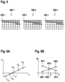
- Figs. 6A and 6B illustrate, in diagrams, values for the at least one geometric feature of the light gap for a plurality of different relative positions between the sample holder and knife holder.
- Fig. 6A values ⁇ 1, ⁇ 2, ⁇ 3, ⁇ 4, ⁇ 5 for an angle ⁇ between the two edges 436.1 and 436.2 of the light gap (see Fig. 4A ), which is related to the width W along the length L are shown versus an angle ⁇ .
- the angle ⁇ corresponds to an angle of rotation of the knife holder about the first axis z'.
- a reference value for the angle ⁇ can set appropriately.
- the five values ⁇ 1, ⁇ 2, ⁇ 3, ⁇ 4, ⁇ 5 for an angle ⁇ are either below or above zero.
- the angle ⁇ should be zero; this corresponds to the edges 436.1 and 436.2 of the light gap being parallel.
- a value ⁇ ' for the angle ⁇ can be determined, which corresponds to the angle ⁇ being zero.
- Such value ⁇ ' can then be set by the first actor such that the knife edge 114 is aligned with and, in particular, is parallel to the front face 124 of the specimen 122. Accuracy can be improved in this way.
- Fig. 6B values for the width W of the light gap (see Fig. 4B ) are shown versus an angle ⁇ .
- the angle ⁇ corresponds to an angle of rotation of the specimen holder about the second axis x (tilt angle).
- a relative movement in the cutting direction c between the knife edge 114 and the specimen 122 can be performed in order to arrange the front face 124 of the specimen 122 parallel to the cutting direction c.
- several values for the width W can be acquired at different relative positions between the sample holder 120 and knife holder 110.
- a first value can be acquired at a relative position where the knife edge 114 is near the upper edge 424.1 of the front face 124 (see Fig. 4B , right side), and second value can be acquired at a relative position where the knife edge 114 is near the lower edge 424.2 of the front face 124 (see Fig. 4B , left side).
- Such values can be acquired for different settings of the angle ⁇ .
- Fig. 6B by means of example, three of such first values W11, W12, W13, and three of such second values W21, W22, W23 obtained for three settings of ⁇ are shown.
- an interpolation line for the first and second values, respectively, is added. This shows that, for example, with increasing the value of angle ⁇ , the width W near the upper edge decreases while the width W near the lower edge increases. As mentioned above, the width W shall be equal for both relative positons.
- the appropriate value of angle ⁇ , where this is achieved, is where both lines are crossing, i.e., value ⁇ '.
- Such value ⁇ ' can then be set by the second actor such that the knife edge 114 is aligned with the front face 124 of the specimen 122 such that the front face 124 is parallel to the cutting direction c. Accuracy can be improved in this way.
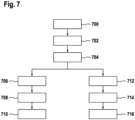
- Fig. 7 illustrates a method according to a further embodiment of the invention by means of a flow diagram. Such method can be performed, for example, using a microtome system 100, 200 or 300 as illustrated in Figs. 1 to 3 and described above.
- the knife 112 can be arranged at or in the knife holder 110 and the specimen 122 can be arranged at or in the specimen holder 120.
- a light gap is generated between the front face 124 of the specimen 122 and the knife edge 114. This can be performed using and/or controlling the illumination 230.
- at least one geometric feature of the light gap 236 is detected by means of the detector 240 (or its camera). Such geometric features can be, for example, the width W or the angle ⁇ mentioned above.
- the knife edge 114 is aligned automatically with the front face 124 of the specimen 122 by controlling, with the controller 250, the first actor 260.1 depending on the detected at least one geometric feature of the light gap.
- This can comprise controlling the first actor 260.1 such that the knife edge 114 is arranged parallel to the front face 124 as explained above, in particular, with respect to Fig. 4A .
- the front face 124 of the specimen 122 is arranged parallel to the cutting direction c by controlling, with the controller 250, the second actor 260.2.
- This can comprise controlling the second actor 260.2 such that the width W remains constant during relative movement in the cutting direction c between the knife edge 114 and the specimen 122 as explained above, in particular, with respect to Fig. 4B .
- the upper edge and/or the lower edge of the front face 124 of the specimen is arranged parallel to the knife edge 114 by controlling, with the controller 250, the third actor 260.3.
- This can comprise controlling the third actor 260.3 such that during relative movement in the cutting direction c between the knife edge 114 and the specimen 122 when held by the specimen holder 120, the at least one geometric feature of the detected light gap 236 comprises a dimension, e.g., width W, that remains constant along the length L of the light gap 236 over a predetermined upper region up to the upper edge of the front face 124 of the specimen 122 and then decreases evenly along the length L of the light gap 236.
- the dimension e.g., the width W, remains constant along the length L of the light gap 236 over a predetermined lower region down to the lower edge of the front face 124 of the specimen 122 and then decreases evenly along the length L of the light gap 236.
- a step 712 can be performed in addition to or alternatively to step 706.
- indications are provided to a user depending on the detected at least one geometric feature of the light gap 236 on how to manually control the first actor in order to align the knife edge 114 with the front face 124 of the specimen 122.
- Such indications might be instructions in text form and/or graphics like assistances lines on a display. Based on such indications, the user can then operate the first actor (it might be motorized but does not need to be in this embodiment) in order to achieve that the knife edge 114 is aligned with the front face 124 of the specimen 122.
- indications might be provided to the user, depending on the detected at least one geometric feature of the light gap, on how to manually control the second actor in order to arrange the front face 124 of the specimen 122 parallel to the cutting direction c.
- indications might be provided to the user, depending on the detected at least one geometric feature of the light gap, on how to manually control the third actor in order to arrange the upper edge and/or the lower edge of the front face 124 of the specimen parallel to the knife edge 114.
- aspects have been described in the context of an apparatus, it is clear that these aspects also represent a description of the corresponding method, where a block or device corresponds to a method step or a feature of a method step. Analogously, aspects described in the context of a method step also represent a description of a corresponding block or item or feature of a corresponding apparatus.
- a microtome system comprising a controller as described in connection with one or more of the Figs. 1 to 3 .
- a microscope may be part of or connected to a system as described in connection with one or more of the Figs. 1 to 3 .
- Fig. 3 shows a schematic illustration of a microtome system 300 configured to perform a method described herein.
- the microtome system 300 comprises a detector 240 and a computer system or controller 250.
- the detector 240 is configured to take images and is connected to the computer system 250.
- the computer system 250 is configured to execute at least a part of a method described herein.
- the computer system 250 may be configured to execute a machine learning algorithm.
- the computer system 250 and detector 240 may be separate entities but can also be integrated together in one common housing.
- the computer system 250 may be part of a central processing system of the detector 240 and/or the computer system 250 may be part of a subcomponent of the detector 240, such as a sensor, an actor, a camera or an illumination unit, etc. of the detector 240.
- the computer system 250 may be a local computer device (e.g. personal computer, laptop, tablet computer or mobile phone) with one or more processors and one or more storage devices or may be a distributed computer system (e.g. a cloud computing system with one or more processors and one or more storage devices distributed at various locations, for example, at a local client and/or one or more remote server farms and/or data centers).
- the computer system 250 may comprise any circuit or combination of circuits.
- the computer system 250 may include one or more processors which can be of any type.
- processor may mean any type of computational circuit, such as but not limited to a microprocessor, a microcontroller, a complex instruction set computing (CISC) microprocessor, a reduced instruction set computing (RISC) microprocessor, a very long instruction word (VLIW) microprocessor, a graphics processor, a digital signal processor (DSP), multiple core processor, a field programmable gate array (FPGA), for example, of a microscope or a microscope component (e.g. camera) or any other type of processor or processing circuit.
- CISC complex instruction set computing
- RISC reduced instruction set computing
- VLIW very long instruction word
- DSP digital signal processor
- FPGA field programmable gate array
- circuits may be included in the computer system 250 may be a custom circuit, an application-specific integrated circuit (ASIC), or the like, such as, for example, one or more circuits (such as a communication circuit) for use in wireless devices like mobile telephones, tablet computers, laptop computers, two-way radios, and similar electronic systems.
- the computer system 250 may include one or more storage devices, which may include one or more memory elements suitable to the particular application, such as a main memory in the form of random access memory (RAM), one or more hard drives, and/or one or more drives that handle removable media such as compact disks (CD), flash memory cards, digital video disk (DVD), and the like.
- RAM random access memory
- CD compact disks
- DVD digital video disk
- the computer system 25 may also include a display device, one or more speakers, and a keyboard and/or controller, which can include a mouse, trackball, touch screen, voice-recognition device, or any other device that permits a system user to input information into and receive information from the computer system 250.
- a display device one or more speakers
- a keyboard and/or controller which can include a mouse, trackball, touch screen, voice-recognition device, or any other device that permits a system user to input information into and receive information from the computer system 250.
- Some or all of the method steps may be executed by (or using) a hardware apparatus, like for example, a processor, a microprocessor, a programmable computer or an electronic circuit. In some embodiments, some one or more of the most important method steps may be executed by such an apparatus.
- embodiments of the invention can be implemented in hardware or in software.
- the implementation can be performed using a non-transitory storage medium such as a digital storage medium, for example a floppy disc, a DVD, a Blu-Ray, a CD, a ROM, a PROM, and EPROM, an EEPROM or a FLASH memory, having electronically readable control signals stored thereon, which cooperate (or are capable of cooperating) with a programmable computer system such that the respective method is performed. Therefore, the digital storage medium may be computer readable.
- Some embodiments according to the invention comprise a data carrier having electronically readable control signals, which are capable of cooperating with a programmable computer system, such that one of the methods described herein is performed.
- embodiments of the present invention can be implemented as a computer program product with a program code, the program code being operative for performing one of the methods when the computer program product runs on a computer.
- the program code may, for example, be stored on a machine readable carrier.
- inventions comprise the computer program for performing one of the methods described herein, stored on a machine readable carrier.
- an embodiment of the present invention is, therefore, a computer program having a program code for performing one of the methods described herein, when the computer program runs on a computer.
- a further embodiment of the present invention is, therefore, a storage medium (or a data carrier, or a computer-readable medium) comprising, stored thereon, the computer program for performing one of the methods described herein when it is performed by a processor.
- the data carrier, the digital storage medium or the recorded medium are typically tangible and/or non-transitionary.
- a further embodiment of the present invention is an apparatus as described herein comprising a processor and the storage medium.
- a further embodiment of the invention is, therefore, a data stream or a sequence of signals representing the computer program for performing one of the methods described herein.
- the data stream or the sequence of signals may, for example, be configured to be transferred via a data communication connection, for example, via the internet.
- a further embodiment comprises a processing means, for example, a computer or a programmable logic device, configured to, or adapted to, perform one of the methods described herein.
- a processing means for example, a computer or a programmable logic device, configured to, or adapted to, perform one of the methods described herein.
- a further embodiment comprises a computer having installed thereon the computer program for performing one of the methods described herein.
- a further embodiment according to the invention comprises an apparatus or a system configured to transfer (for example, electronically or optically) a computer program for performing one of the methods described herein to a receiver.
- the receiver may, for example, be a computer, a mobile device, a memory device or the like.
- the apparatus or system may, for example, comprise a file server for transferring the computer program to the receiver.
- a programmable logic device for example, a field programmable gate array
- a field programmable gate array may cooperate with a microprocessor in order to perform one of the methods described herein.
- the methods are preferably performed by any hardware apparatus.
Landscapes
- Physics & Mathematics (AREA)
- Health & Medical Sciences (AREA)
- Life Sciences & Earth Sciences (AREA)
- Chemical & Material Sciences (AREA)
- Analytical Chemistry (AREA)
- Biochemistry (AREA)
- General Health & Medical Sciences (AREA)
- General Physics & Mathematics (AREA)
- Immunology (AREA)
- Pathology (AREA)
- Sampling And Sample Adjustment (AREA)
- Microscoopes, Condenser (AREA)
Priority Applications (4)
| Application Number | Priority Date | Filing Date | Title |
|---|---|---|---|
| EP22169921.8A EP4269983A1 (de) | 2022-04-26 | 2022-04-26 | Mikrotomsystem und entsprechendes verfahren |
| US18/299,759 US20230341298A1 (en) | 2022-04-26 | 2023-04-13 | Microtome system and corresponding method |
| JP2023071583A JP2023162152A (ja) | 2022-04-26 | 2023-04-25 | ミクロトームシステムおよび対応する方法 |
| CN202310469643.XA CN116952641A (zh) | 2022-04-26 | 2023-04-26 | 切片机系统及相应的方法 |
Applications Claiming Priority (1)
| Application Number | Priority Date | Filing Date | Title |
|---|---|---|---|
| EP22169921.8A EP4269983A1 (de) | 2022-04-26 | 2022-04-26 | Mikrotomsystem und entsprechendes verfahren |
Publications (1)
| Publication Number | Publication Date |
|---|---|
| EP4269983A1 true EP4269983A1 (de) | 2023-11-01 |
Family
ID=81387231
Family Applications (1)
| Application Number | Title | Priority Date | Filing Date |
|---|---|---|---|
| EP22169921.8A Pending EP4269983A1 (de) | 2022-04-26 | 2022-04-26 | Mikrotomsystem und entsprechendes verfahren |
Country Status (4)
| Country | Link |
|---|---|
| US (1) | US20230341298A1 (de) |
| EP (1) | EP4269983A1 (de) |
| JP (1) | JP2023162152A (de) |
| CN (1) | CN116952641A (de) |
Citations (5)
| Publication number | Priority date | Publication date | Assignee | Title |
|---|---|---|---|---|
| JPS50129981U (de) * | 1974-04-09 | 1975-10-24 | ||
| EP0098818A1 (de) * | 1982-06-28 | 1984-01-18 | Reichert-Jung Optische Werke AG | Verfahren zur Herstellung eines sehr kleinen Abstandes zwischen Messerschneide und Probe bei einem Mikrotom |
| US20040035275A1 (en) * | 2002-06-28 | 2004-02-26 | Reinhard Lihl | Illumination device for microtomes and ultramicrotomes |
| US20170336300A1 (en) * | 2016-05-19 | 2017-11-23 | Herbert Luttenberger | Microtome |
| US10054518B2 (en) * | 2013-11-05 | 2018-08-21 | Howard Hughes Medical Institute | Sectioning volume samples |
-
2022
- 2022-04-26 EP EP22169921.8A patent/EP4269983A1/de active Pending
-
2023
- 2023-04-13 US US18/299,759 patent/US20230341298A1/en active Pending
- 2023-04-25 JP JP2023071583A patent/JP2023162152A/ja active Pending
- 2023-04-26 CN CN202310469643.XA patent/CN116952641A/zh active Pending
Patent Citations (5)
| Publication number | Priority date | Publication date | Assignee | Title |
|---|---|---|---|---|
| JPS50129981U (de) * | 1974-04-09 | 1975-10-24 | ||
| EP0098818A1 (de) * | 1982-06-28 | 1984-01-18 | Reichert-Jung Optische Werke AG | Verfahren zur Herstellung eines sehr kleinen Abstandes zwischen Messerschneide und Probe bei einem Mikrotom |
| US20040035275A1 (en) * | 2002-06-28 | 2004-02-26 | Reinhard Lihl | Illumination device for microtomes and ultramicrotomes |
| US10054518B2 (en) * | 2013-11-05 | 2018-08-21 | Howard Hughes Medical Institute | Sectioning volume samples |
| US20170336300A1 (en) * | 2016-05-19 | 2017-11-23 | Herbert Luttenberger | Microtome |
Also Published As
| Publication number | Publication date |
|---|---|
| US20230341298A1 (en) | 2023-10-26 |
| JP2023162152A (ja) | 2023-11-08 |
| CN116952641A (zh) | 2023-10-27 |
Similar Documents
| Publication | Publication Date | Title |
|---|---|---|
| US11847751B2 (en) | Method and system for implementing augmented reality (AR)-based assistance within work environment | |
| US11774735B2 (en) | System and method for performing automated analysis of air samples | |
| US8417006B2 (en) | System and method for improved viewing and navigation of digital images | |
| US8325414B2 (en) | Apparatus for single-handed control of microscope functions | |
| JP2022507695A (ja) | イメージ比較のための試料撮像及びイメージアーカイビング | |
| US20110198496A1 (en) | Mass Spectrometer | |
| US7522763B2 (en) | Method of measuring occluded features for high precision machine vision metrology | |
| WO2006023675A2 (en) | Microscopy system having automatic and interactive modes for forming a magnified mosaic image and associated method | |
| CN101910907B (zh) | 用于可控地扫描细胞样本的方法和系统 | |
| US11106178B2 (en) | Cell observation device | |
| US20170053394A1 (en) | Inspection apparatus, inspection method, and article manufacturing method | |
| CN107110749B (zh) | 用于激光显微切割的方法和激光显微切割系统 | |
| EP4269983A1 (de) | Mikrotomsystem und entsprechendes verfahren | |
| EP1408326A2 (de) | Verfahren und Vorrichtung zur Untersuchung von Oberflächen | |
| CN115014724B (zh) | 一种衍射光波导的测试系统、方法和装置 | |
| US9830702B2 (en) | Dynamic real-time layout overlay | |
| JP2023092515A (ja) | 顕微鏡制御装置 | |
| US20230266819A1 (en) | Annotation data collection using gaze-based tracking | |
| US10692232B2 (en) | Shape reconstruction of specular and/or diffuse objects using multiple layers of movable sheets | |
| US10453650B2 (en) | Charged particle beam apparatus, observation method using charged particle beam apparatus, and program | |
| US20230221214A1 (en) | Method for generating a series of ultra-thin sections using an ultramicrotome, method for three-dimensional reconstruction of a microscopic sample, ultramicrotome system and computer program | |
| CN108804489B (zh) | 计算机中目标文档远程监控系统 | |
| CN115407907A (zh) | 一种基于3d显示的刀路图交互方法及装置 |
Legal Events
| Date | Code | Title | Description |
|---|---|---|---|
| PUAI | Public reference made under article 153(3) epc to a published international application that has entered the european phase |
Free format text: ORIGINAL CODE: 0009012 |
|
| STAA | Information on the status of an ep patent application or granted ep patent |
Free format text: STATUS: THE APPLICATION HAS BEEN PUBLISHED |
|
| AK | Designated contracting states |
Kind code of ref document: A1 Designated state(s): AL AT BE BG CH CY CZ DE DK EE ES FI FR GB GR HR HU IE IS IT LI LT LU LV MC MK MT NL NO PL PT RO RS SE SI SK SM TR |
|
| STAA | Information on the status of an ep patent application or granted ep patent |
Free format text: STATUS: REQUEST FOR EXAMINATION WAS MADE |