US10692232B2 - Shape reconstruction of specular and/or diffuse objects using multiple layers of movable sheets - Google Patents
Shape reconstruction of specular and/or diffuse objects using multiple layers of movable sheets Download PDFInfo
- Publication number
- US10692232B2 US10692232B2 US15/836,757 US201715836757A US10692232B2 US 10692232 B2 US10692232 B2 US 10692232B2 US 201715836757 A US201715836757 A US 201715836757A US 10692232 B2 US10692232 B2 US 10692232B2
- Authority
- US
- United States
- Prior art keywords
- sheet
- shape
- pattern
- specular
- pattern region
- Prior art date
- Legal status (The legal status is an assumption and is not a legal conclusion. Google has not performed a legal analysis and makes no representation as to the accuracy of the status listed.)
- Active, expires
Links
Images


Classifications
-
- G—PHYSICS
- G06—COMPUTING OR CALCULATING; COUNTING
- G06T—IMAGE DATA PROCESSING OR GENERATION, IN GENERAL
- G06T7/00—Image analysis
- G06T7/50—Depth or shape recovery
- G06T7/521—Depth or shape recovery from laser ranging, e.g. using interferometry; from the projection of structured light
-
- G—PHYSICS
- G01—MEASURING; TESTING
- G01B—MEASURING LENGTH, THICKNESS OR SIMILAR LINEAR DIMENSIONS; MEASURING ANGLES; MEASURING AREAS; MEASURING IRREGULARITIES OF SURFACES OR CONTOURS
- G01B11/00—Measuring arrangements characterised by the use of optical techniques
- G01B11/24—Measuring arrangements characterised by the use of optical techniques for measuring contours or curvatures
- G01B11/25—Measuring arrangements characterised by the use of optical techniques for measuring contours or curvatures by projecting a pattern, e.g. one or more lines, moiré fringes on the object
- G01B11/2518—Projection by scanning of the object
- G01B11/2522—Projection by scanning of the object the position of the object changing and being recorded
-
- G—PHYSICS
- G01—MEASURING; TESTING
- G01B—MEASURING LENGTH, THICKNESS OR SIMILAR LINEAR DIMENSIONS; MEASURING ANGLES; MEASURING AREAS; MEASURING IRREGULARITIES OF SURFACES OR CONTOURS
- G01B11/00—Measuring arrangements characterised by the use of optical techniques
- G01B11/24—Measuring arrangements characterised by the use of optical techniques for measuring contours or curvatures
- G01B11/25—Measuring arrangements characterised by the use of optical techniques for measuring contours or curvatures by projecting a pattern, e.g. one or more lines, moiré fringes on the object
- G01B11/2536—Measuring arrangements characterised by the use of optical techniques for measuring contours or curvatures by projecting a pattern, e.g. one or more lines, moiré fringes on the object using several gratings with variable grating pitch, projected on the object with the same angle of incidence
-
- G—PHYSICS
- G06—COMPUTING OR CALCULATING; COUNTING
- G06T—IMAGE DATA PROCESSING OR GENERATION, IN GENERAL
- G06T15/00—Three-dimensional [3D] image rendering
- G06T15/04—Texture mapping
-
- G—PHYSICS
- G06—COMPUTING OR CALCULATING; COUNTING
- G06T—IMAGE DATA PROCESSING OR GENERATION, IN GENERAL
- G06T15/00—Three-dimensional [3D] image rendering
- G06T15/06—Ray-tracing
-
- G—PHYSICS
- G06—COMPUTING OR CALCULATING; COUNTING
- G06T—IMAGE DATA PROCESSING OR GENERATION, IN GENERAL
- G06T17/00—Three-dimensional [3D] modelling for computer graphics
-
- G—PHYSICS
- G02—OPTICS
- G02B—OPTICAL ELEMENTS, SYSTEMS OR APPARATUS
- G02B5/00—Optical elements other than lenses
- G02B5/02—Diffusing elements; Afocal elements
- G02B5/0273—Diffusing elements; Afocal elements characterized by the use
- G02B5/0278—Diffusing elements; Afocal elements characterized by the use used in transmission
-
- G—PHYSICS
- G06—COMPUTING OR CALCULATING; COUNTING
- G06T—IMAGE DATA PROCESSING OR GENERATION, IN GENERAL
- G06T2207/00—Indexing scheme for image analysis or image enhancement
- G06T2207/10—Image acquisition modality
- G06T2207/10004—Still image; Photographic image
-
- G—PHYSICS
- G06—COMPUTING OR CALCULATING; COUNTING
- G06T—IMAGE DATA PROCESSING OR GENERATION, IN GENERAL
- G06T2207/00—Indexing scheme for image analysis or image enhancement
- G06T2207/30—Subject of image; Context of image processing
- G06T2207/30108—Industrial image inspection
-
- G—PHYSICS
- G06—COMPUTING OR CALCULATING; COUNTING
- G06T—IMAGE DATA PROCESSING OR GENERATION, IN GENERAL
- G06T2215/00—Indexing scheme for image rendering
- G06T2215/16—Using real world measurements to influence rendering
Definitions
- the present disclosure relates shape reconstruction of physical objects using structured light and multiple layers of movable sheets which each include a transparent or windowed area, and is particularly well-suited for shape reconstruction of objects having a mirror-like or specular surface.
- 3D reconstruction of a specular object remains a challenging task. While there are several techniques capable of accurate reconstruction of objects with a diffuse (also called Lambertian) surface, the 3D reconstruction of an object with a specular (or non-Lambertian) surface is still an open problem.
- reflection by the object may be quite complicated, and in general may involve multiple reflections by the object itself, in the path of reflection from a light source to image capture. These multiple reflections violate underlying assumptions of conventional reconstruction techniques on the nature of reflections by the surface of the object, which typically assume only a single reflection at the surface of the object. Thus, the multiple reflections destabilize and otherwise invalidate calculations based on ray tracing or triangulation, at least to the extent that such calculations rely on the assumption of only a single reflection at the surface of the object.
- the foregoing applications include the use of plural transparency-controllable layers, such as multiple layers of E-glass, which are switchable between a transparent mode in which the glass is completely transparent, and a diffuse mode in which the glass assumes a frosted appearance. Images can be projected on or reflected onto the frosted appearance of the diffuse mode, and images captured thereby can be analyzed so as to reconstruct the 3D shape of an object under inspection. For example, sequences of coded patterns such as binary Gray scale patterns can be projected onto the E-glass layers while in the diffuse mode, and distorted images of these patterns, as reflected by the specular surface of a glossy object, can be analyzed to reconstruct the surface shape of the object.
- E-glass layers and other transparency-controllable layers such as LCD panels, have the convenience of electronic control without mechanical parts, they are sometimes not well-suited to particular environments or usage scenarios.
- E-glass layers are generally heavy and require sturdy mounts. They can be relatively costly, particularly in consumer-based usage scenarios, and sometimes difficult to obtain commercially.
- design decisions are made with respect to parameters such as pixel size, it is difficult to inject flexible into the resulting system.
- reconstruction of the 3D shape of an object involves first and second movable sheets positioned in spaced-apart relation relative to each other.
- Each of the first and second sheets is movable to expose at least one transparent region and at least one pattern region to the inspection station.
- the pattern region is configured to bear a coded pattern thereon, such as by projection of a coded pattern thereon or by a sequence of patterns pre-printed or formed directly onto an elongate pattern region.
- the pattern regions of the first and second sheets are translucent, such that the projected pattern is visible from the reverse side of the sheet.
- Shape reconstruction of diffuse regions on the surface of the object may proceed by moving both of the first and second sheets to expose the transparent region, and by projecting patterned light onto the object. Based on captured images of the pattern projected onto the object, the shape of the surface of an object having at least some diffuse characteristics may be reconstructed. Diffuse components may be separated from specular components in the captured images, such as by use of varying angles of polarization in polarized light, and the shape of the surface of the object may be reconstructed using the diffuse components.
- Shape reconstruction of specular regions on the surface of the object may proceed by first and second phases.
- first phase the first sheet is moved to the pattern region and the second sheet is moved to the transparent region, and a first sequence of patterned light is projected onto the pattern region of the first sheet.
- second phase the first sheet is moved to the transparent region and the second sheet is moved to the pattern region, and a second sequence of patterned light is projected onto the pattern region of the second sheet.
- Diffuse components may be separated from specular components in the captured images, such as by use of varying angles of polarization in polarized light, and the shape of the surface of the object may be reconstructed using the specular components.
- Direct reflections from the object may be differentiated from intra-object reflections by extracting a visual hull of the object, separating between light paths having direct single reflections and light paths having indirect multi-reflections in the images of the reflected patterns, by calculations using the visual hull, and reconstructing the shape of the surface of the object using the light paths having direct single reflections.
- the coded sequences of patterned light may comprise a sequence of binary patterns of horizontal and vertical stripe patterns, wherein each pattern in the sequence has a spatial frequency that differs from others of the patterns in the sequence, such as patterns formed using binary Gray codes.
- coded patterns are pre-printed or formed directly onto an elongate pattern region.
- the coded sequences of patterns may comprise a sequence of binary patterns of horizontal and vertical stripe patterns, wherein each pattern in the sequence has a spatial frequency that differs from others of the patterns in the sequence, such as patterns formed using binary Gray codes.
- Shape reconstruction of specular regions on the surface of the object may proceed by first and second phases. In the first phase the first sheet is moved to each sequential pattern of the pattern region and the second sheet is moved to the transparent region. In the second phase the first sheet is moved to the transparent region and the second sheet is moved to each sequential pattern of the pattern region. Based on wherein based on the captured images, the shape of the surface of an object having at least some specular characteristics is reconstructed.
- the sheets may be transparent and they may be opaque or translucent, in which case the transparent regions may be formed by windows removed from the sheets.
- FIGS. 1A and 1B are views showing a movable sheet movable by rollers to expose a transparent region as shown in FIG. 1A and a pattern region as shown in FIG. 1B .
- FIG. 1C is a view showing the unrolled sheet depicted in FIGS. 1A and 1B .
- FIG. 1D is a view showing a linear encoder for precise positioning of the movable sheet.
- FIG. 2 is a view depicting first and second movable sheets positioned in spaced-apart relation relative to each other.
- FIG. 3 is a view showing one example embodiment of a system for recovery of surface shape of an object which may have diffuse and/or specular regions, using the movable sheets of FIGS. 1A through 1C .
- FIG. 4 is a view for explaining one embodiment of the architecture of the controller shown in FIG. 3 .
- FIG. 5 shows an example of 2D visual hull for an object that includes concave areas.
- FIG. 6 is an illustration of a multi-bounce path, demonstrating that for a multi-bounce situation, the light rays meet outside the visual-hull of the object.
- FIG. 7 is a flow diagram for explaining shape reconstruction according to the disclosure herein.
- FIG. 8 is a view showing an unrolled elongate movable sheet in which coded patterns are pre-printed or formed directly onto an elongate pattern region.
- FIG. 9 is a view showing one example embodiment of a system for recovery of surface shape of an object which may have diffuse and/or specular regions, using the movable sheets depicted in FIG. 8 .
- FIG. 10 is a flow diagram for explaining shape reconstruction according to the disclosure herein.
- FIGS. 11A and 11B are views depicting movable sheets that are transparent.
- FIGS. 1A and 1B are views showing a movable sheet 20 movable by rollers 21 to expose a transparent region 22 as shown in FIG. 1A and a pattern region 23 as shown in FIG. 1B .
- sheet 20 is translucent such that images projected onto the obverse side of pattern region 23 are visible from the reverse side thereof.
- Transparent region 22 is formed by a window cut out from sheet 20 .
- FIG. 1C is a view showing sheet 20 in unrolled form.
- the movable sheets described herein have at least one transparent region and at least one pattern region.
- this embodiment uses one transparent region 22 in the form of a cut out window, and one pattern region 23 onto which coded patterns may be projected.
- FIG. 1D is a view showing a linear encoder.
- precise positioning of the movable sheet is helpful, such as for repeated re-positionings of the sheet to the same position, or for precision in relative positioning as between a first movable sheet and second movable sheet.
- Such embodiments may use a linear encoder such as that shown in FIG. 1D in which a codestrip 24 is affixed to the edge of sheet 20 , and an encoder 25 optically encodes the position of the codestrip.
- FIG. 2 is a view depicting first and second movable sheets positioned in spaced-apart relation relative to each other.
- the sheets are movable independently such as on rollers.
- a first sheet is moved so that the transparent region is exposed, while the second sheet is moved so that the pattern region is exposed.
- a coded pattern 26 is shown as projected onto the pattern region of the second sheet.
- FIG. 3 is a view showing one example embodiment of a system for recovery of surface shape of objects such as objects whose reflection characteristics include both a specular component and a diffuse component, in the form of a replication system 10 in which surface shape of objects is recovered for replication, for example, for 3D replication of the object physically (such as with a 3D printer) or representationally (as with a graphics display).
- FIG. 3 depicts a replication environment
- this is simply an example environment in which the disclosure herein may be practiced, and that other environments or embodiments are of course possible.
- recovery of surface shape can also be used in the context of automated inspection, robotics, gripping and positioning, machine vision, quality control, defect detection, image retrieval, shape modelling and scene reconstruction, security and so forth, among many others.
- an object 11 is positioned at an inspection station 12 , which in this embodiment is the surface of a movable stage 14 by which the object can be moved into varying perspectives.
- the movable stage is movable by rotation about a vertical axis, and in other embodiments the movable stage may be a 3-axis positioning table.
- Object 11 is typically a specular object or a mirror-like object, or other similar object with a glossy or highly glossy surface, exhibiting reflection characteristics that include both specular and diffuse components.
- Movable stage 14 is moved under control of actuator 15 , via motion commands issued by controller 100 for reconstruction of surface shape.
- Controller 100 is configured to reconstruct surface shape of objects at inspection station 12 , based on commands issued to projector 101 , commands issued to movable sheets 103 at rolling diffuser stations # 1 and # 2 , and commands issued to actuator 15 for movable stage 14 ; and based on image data received from an image capture system which in this embodiment includes digital cameras 102 a and 102 b . Based on the reconstruction obtained by controller 100 , controller 100 controls replication controller 104 so as to obtain a 3D replication of the object. In this embodiment, 3D replication of the object is obtained physically via 3D printer 105 , to produce replicated object 106 . In other embodiments, 3D replication of the object may be obtained representationally via a graphics display. More details of controller 100 are provided below, such as in connection with FIG. 3 .
- FIG. 3 further depicts plural movable sheets 103 , positioned in spaced-apart relation relative to each other.
- each movable sheet Under control from controller 100 , each movable sheet is independently movable so as to expose its transparent region 22 and its pattern region 23 .
- the movable sheets 103 are positioned in spaced-apart relation to each other, such that by using the relative positionings of the movable sheets to projector 101 and cameras 102 a and 102 b , ray-tracing and/or triangulation techniques allow reconstruction of the 3D surface shape of the object 11 under inspection.
- the relative positionings are predetermined through calibration. More details on the relative positionings of movable sheets 103 , relative to other elements such as projector 101 and the image capture system, and calibration, are described in the afore-mentioned U.S. application Ser. No. 15/072,101, which is incorporated by reference.
- the FIG. 3 embodiment also includes a pair of polarizers, one configured to polarize light and the other configured to analyze polarized light.
- the first polarizer is positioned between the E-glass layers and the object, so as to polarize light illuminated toward the object.
- the second polarizer is positioned in front of camera 102 b so as to permit analysis of the polarization state of light reflected from the object.
- one is used as a polarizer to polarize the incident light before it reaches the object; and the other is used as an analyzer to analyze the light reflected off the object.
- Either the analyzer or the polarizer can rotate, or both can rotate.
- the pair of polarizers are usable to separate a diffuse component of reflection from a specular component of reflection.
- Each surface point on highly glossy or heterogeneous objects will typically reflect in both modes, and separation of each component facilitates accurate surface reconstruction for such objects.
- the polarizers may be omitted, and processing to separate diffuse and specular components of reflection may likewise be omitted.
- all movable sheets are positioned to the transparent region, and projector 101 projects the patterns directly onto the surface of the diffuse object.
- the state of polarization is varied, and camera 102 b captures images of the patterns as projected onto the object.
- the nature and intensity of the captured images varies in accordance with the variation in the state of polarization, which allows for separation of diffuse and specular components of reflection.
- the diffuse component allows the depth for each pixel of the object at the inspection station to be calculated based on traditional triangulation methodology.
- each different one of the movable sheets is in turn moved to expose its pattern region set with all others moved to expose the transparent region, and projector 101 projects patterns so as to illuminate the object by the patterns projected onto the pattern region.
- the state of polarization is varied, and images are captured of the structured light pattern as reflected by the glossy surface of the object.
- the nature and intensity of the captured images varies in accordance with the variation in the state of polarization, which allows for separation of diffuse and specular components of reflection.
- the 3D shape of the entirety of the visible surface of the object can be reconstructed by analysis of the specular component of the captured images of the distorted reflections of the patterns caused by the surface of the object.
- the polarizer and the analyzer may be omitted.
- the position of camera and the movable sheets 103 are determined during a calibration process and stored for later computations.
- the correspondences between camera pixels and points of the patterns projected onto the movable sheets are established by projecting coded patterns, different from each other, such that each location on the sheet is uniquely identifiable.
- the patterns may, for example, be patterns of horizontal and vertical stripe patterns, such as binary patterns, each pattern in the sequence having a spatial frequency that differs from others of the patterns in the sequence, such as Gray code patterns.
- Projector 101 in this embodiment has an autofocus function, by which patterns projected by the projector are automatically focused onto the surface where the patterns are projected.
- This provides an advantageous benefit: because the movable sheets are moved to expose transparent regions and pattern regions.
- the surface onto which patterns are projected is likewise changed. For example, in a circumstance when an innermost movable sheet at rolling diffuser # 1 is moved to expose the pattern region, patterns are projected onto the innermost layer.
- the focus distance in this circumstance differs from a circumstance when the innermost movable sheet at diffuser # 1 is moved to expose the transparent region and the outermost sheet at diffuser # 2 is moved to expose the pattern region. In this case, patterns are projected onto the outermost sheet.
- Both of these focus distances are different from the circumstance when all movable sheets are moved to expose their transparent regions, the object is diffuse, and patterns are projected directly onto the surface of the diffuse object.
- the autofocus function of projector 101 responds automatically to these changes in focus distance, ensuring that the projected patterns remain in focus regardless of the surface onto which they are projected.
- controller 100 provides commands to the pair of polarizers (i.e., to the polarizer and to the analyzer), position commands (for example, to expose the pattern region vs. the transparent region) to the movable sheets 103 , pattern commands (such as Gray code patterns) to the projector, motion commands to the movable stage, and replication commands to the replication controller.
- position commands for example, to expose the pattern region vs. the transparent region
- pattern commands such as Gray code patterns
- Controller 100 receives image data from the image capture system, and uses the image data for functionality which includes functionality to extract a silhouette of the object, functionality to construct a visual hull for the object, functionality to separate diffuse and specular components of reflection in the captured images, functionality to determine the number of reflections encountered by a light ray reflected by the surface of the object (sometimes referred to herein as the number of “bounces”), and functionality to reconstruct the 3D surface shape of the object based on the captured image data.
- functionality which includes functionality to extract a silhouette of the object, functionality to construct a visual hull for the object, functionality to separate diffuse and specular components of reflection in the captured images, functionality to determine the number of reflections encountered by a light ray reflected by the surface of the object (sometimes referred to herein as the number of “bounces”), and functionality to reconstruct the 3D surface shape of the object based on the captured image data.
- FIG. 4 is a view for explaining one embodiment of the architecture of controller 100 for shape reconstruction of objects at inspection station 12 .
- controller 100 includes central processing unit (CPU) 110 which interfaces with computer bus 109 . Also interfacing with computer bus 109 are network interface 111 , keyboard interface 112 , camera interface 113 which interfaces to the image capture system including cameras 102 a and 102 b , projector interface 114 which interfaces to projector 101 , layer interface 115 which interfaces to the plural movable sheets 103 and to the polarizer and the analyzer, movable stage interface 118 which interfaces to actuator 15 of movable stage 14 , random access memory (RAM) 116 for use as a main run-time transient memory, read only memory (ROM) 116 a , replication interface 117 for interface to replication controller 104 , and non-volatile memory 180 (e.g., a hard disk or other nonvolatile and non-transitory storage medium).
- CPU central processing unit
- network interface 111 keyboard interface 112
- camera interface 113 which interfaces to the image capture system including cameras 102 a and 102 b
- RAM 116 interfaces with computer bus 109 so as to provide information stored in RAM 116 to CPU 110 during execution of the instructions in software programs, such as an operating system, application programs, image processing modules, and device drivers. More specifically, CPU 110 first loads computer-executable process steps from non-volatile memory 180 or another storage device into a region of RAM 116 . CPU 110 can then execute the stored process steps from RAM 116 in order to execute the loaded computer-executable process steps. Data also can be stored in RAM 116 so that the data can be accessed by CPU 110 during the execution of the computer-executable software programs, to the extent that such software programs have a need to access and/or modify the data.
- software programs such as an operating system, application programs, image processing modules, and device drivers. More specifically, CPU 110 first loads computer-executable process steps from non-volatile memory 180 or another storage device into a region of RAM 116 . CPU 110 can then execute the stored process steps from RAM 116 in order to execute the loaded computer-executable process steps. Data also can be stored
- non-volatile memory 180 contains computer-executable process steps for operating system 181 and for application programs 182 , such as graphic image management programs.
- Non-volatile memory 180 also contains computer-executable process steps for device drivers for software interface to devices, such as input device drivers 183 , output device drivers 184 , and other device drivers 185 .
- Non-volatile memory 180 also stores a shape recovery module 140 , a positioning control module 150 , and replication control module 180 .
- These modules i.e., the shape recovery module 140 , the positioning control module 150 , and the replication control module 180 , are comprised of computer-executable process steps for 3D shape reconstruction of the surface shape of an object, for repositioning of the object on movable stage 14 , and for control of replication controller 104 for 3D replication of the object.
- shape recovery module 140 generally comprises silhouette extraction module 141 for extracting a silhouette of a foreground object positioned against a background, a visual hull construction module 142 for constructing a visual hull using the extracted silhouette, a reflection bounce determination module 143 for determining the number of bounces encountered at the surface of the object by a light ray, and shape recovery module 144 for recovery of surface shape of the object under inspection.
- Shape recovery module 140 also generally comprises a rolling diffuser position control module 145 for control over the position of each of the plural sheets 103 , a projector pattern control module 146 which stores one or more background patterns together with plural sequences of patterned light patterns and which controls projection of the plural sequences of background patterns and patterned light patterns by projector 101 , as well as image capture control module 147 for control of image capture by image capturing system 102 .
- Unshown in FIG. 4 is a further module, also stored in non-volatile memory 180 , for control over the pair of polarizers, so as to rotate the polarizer and/or the analyzer and alter the state of polarization, for those embodiments that separate diffuse and specular components of reflection.
- Positioning control module 150 controls repositioning of the object on movable stage 14
- replication control module 180 controls replication controller 104 for 3D replication of the object.
- controller 100 issues positioning commands to reposition movable stage 14 and the object thereon.
- multiple silhouettes of the foreground object may be extracted.
- the extracted silhouettes may be used to construct a visual hull of the object, and the visual hull may be used to determine the number of bounces for a reflected light ray.
- Repositioning of the object exposes other areas of its surface to image capture and illumination by the layers, and thereby permits 3D shape reconstruction with as much of the entirety of the object as desired.
- the computer-executable process steps for these modules may be configured as part of operating system 181 , as part of an output device driver in output device drivers 121 , or as a stand-alone application program(s). These modules may also be configured as a plug-in or dynamic link library (DLL) to the operating system, device driver or application program. It can be appreciated that the present disclosure is not limited to these embodiments and that the disclosed modules may be used in other environments.
- DLL dynamic link library
- some embodiments may differentiate between light paths having direct single reflections and light paths having indirect multi-reflections, and some embodiments may not make such a differentiation.
- shape reconstruction is able to use light paths corresponding to direct single reflection and to ignore light paths having indirect multi-reflections such as intra-object reflections.
- Such differentiation is described in detail in the afore-mentioned Application No. 62/361,415 and Application No. 62/367,600, incorporated by reference herein.
- 0-bounce camera rays (corresponding to camera pixels) that do not hit the target object.
- the system described herein utilizes shape reconstruction techniques which distinguish between these three categories. Principally, the technique is divided in two tasks: (1) Reconstruct the visual hull of the object; and (2) Starting from the visual hull, measure the shape by triangulating only the direct paths (i.e., the 1-bounce paths).
- the first task is achieved by extracting the silhouette of the object at each view and then combining them together using the angle of rotation of each pose/camera. Extraction of the silhouette, and construction of the visual hull, is described in the afore-mentioned U.S. Application No. 62/323,531.
- FIG. 5 shows an example of a 2D visual hull 31 for an object 32 that includes concave areas such as area 33 .
- the visual hull is estimated by combining silhouettes from different viewpoints. As shown in FIG. 5 , concave regions cannot be properly reconstructed using only the visual hull.
- the second task is performed, so as to distinguish the 1-bounce paths and to triangulate using only the 1-bounce paths.
- One challenge of the second task is to distinguish direct reflections (1-bounce paths) from multi-reflections (N-bounce paths). As explained in Application No. 62/367,600, distinguishing direct, single bounce reflections capitalizes on three properties of light ray reflection in the system.
- Property #1 In a direct reflection (1-bounce paths), the camera ray (given by the camera pixel) and the light ray (given by the code read from the screens) are coplanar; in other words they lie on the epipolar plane.
- Property #2 A generic multi-bounce path (N-bounce paths) usually does not keep the rays coplanar. This has been demonstrated by M. O'Toole et al., cited above, and acts as a computationally-simple first step in determining whether to exclude a reflection from the reconstruction of surface shape.
- FIG. 6 is an illustration of a multi-bounce path, demonstrating that for a multi-bounce situation, the light rays meet outside the visual-hull of the object. This is consistent with property #3.
- direct paths are distinguished from multi-reflection paths based at least on whether the rays do or do not meet inside the visual hull.
- FIG. 7 is a flow diagram for explaining shape reconstruction according to the disclosure herein.
- the process steps shown in FIG. 7 are stored on non-transitory memory such as fixed disk 180 and are executed by CPU 100 of controller 100 .
- steps S 701 and S 702 In connection with the steps shown in FIG. 7 , in steps S 701 and S 702 , all rolling diffusers are positioned to expose their transparent regions, a silhouette of the object is extracted, and a visual hull for the object is extracted. As mentioned above, for embodiments that do not differentiate between light paths having direct single reflections and light paths having indirect multi-reflections, steps S 701 and S 702 may be omitted.
- step S 703 rolling diffuser # 2 is positioned to expose its pattern region and all other rolling diffusers are positioned to expose their transparent regions.
- step S 704 projector 101 makes repeated projections of coded patterns onto the pattern region of the movable sheet in rolling diffuser # 2 , and corresponding images of the distorted reflections of these patterns, as reflected by the surface of the object, are captured.
- step S 705 the polarizer and/or analyzer are repositioned so as to vary the angle of polarization, the projections and captures of step S 704 are repeated.
- step S 705 with its repositioning of the polarizer and the analyzer, and its repetition of projections and image captures, may be omitted.
- rolling diffuser # 1 is positioned to expose its pattern region and all other rolling diffusers are positioned to expose their transparent regions.
- step S 707 projector 101 makes repeated projections of coded patterns onto the pattern region of the movable sheet in rolling diffuser # 1 , and corresponding images of the distorted reflections of these patterns, as reflected by the surface of the object, are captured.
- step S 708 the polarizer and/or analyzer are repositioned so as to vary the angle of polarization, the projections and captures of step S 707 are repeated.
- step S 708 with its repositioning of the polarizer and the analyzer, and its repetition of projections and image captures, may be omitted.
- step S 709 for embodiments which do separate the diffuse component of reflection from the specular component of reflection, the diffuse and specular components are separated.
- step S 710 diffuse regions of the object are reconstructed using diffuse components of reflection. This step may be omitted for embodiments that reconstruct specular objects not containing significant diffuse regions.
- step S 711 for embodiments that do differentiate between light paths having direct single reflections and light paths having indirect multi-reflections, light paths having a direct single reflection are determined based on intersection with the visual hull extracted in step S 702 . For embodiments that do not differentiate between light paths having direct single reflections and light paths having indirect multi-reflections, step S 711 may be omitted.
- step S 712 the surface shape of specular regions of the object is reconstructed using the captured images.
- light paths having indirect multi-reflections are exclude, and only light paths having a direct single reflection, as determined in step S 711 , are used.
- FIG. 8 is a view showing an unrolled elongate movable sheet according to a second embodiment, in which coded patterns are pre-printed or formed directly onto an elongate web which includes multiple pattern regions.
- an elongate sheet 220 includes a transparent region 221 and multiple pattern regions such as regions 222 a , 222 b , 223 a and 223 b .
- Each of the patterned regions has formed thereon a coded pattern such as a Gray code pattern.
- pattern regions 222 a and 22 b are Gray code patterns in the horizontal direction
- pattern regions 223 a and 223 b are Gray code patterns in the vertical direction.
- first and second ones of movable sheets 220 are positioned in spaced-apart relation relative to each other.
- the sheets are movable independently such as on rollers.
- a linear encoder such as that shown in FIG. 1D may be affixed to the edge of each sheet, for purposes of accurate positionings and re-positionings.
- FIG. 9 is a view showing one example embodiment of a system for recovery of surface shape of an object which may have diffuse and/or specular regions, using the movable sheets depicted in FIG. 8 .
- Reference numbers used in FIG. 9 are similar to reference numbers used in FIG. 3 , and a detailed description thereof is therefore omitted in the interests of brevity.
- a projector may be omitted.
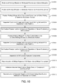
- FIG. 10 is a flow diagram for explaining shape reconstruction according to the disclosure herein.
- steps S 1001 and S 1002 all rolling diffusers are positioned to expose their transparent regions, a silhouette of the object is extracted, and a visual hull for the object is extracted. As mentioned above, for embodiments that do not differentiate between light paths having direct single reflections and light paths having indirect multi-reflections, steps S 1001 and S 1002 may be omitted.
- rolling diffuser # 2 is positioned to expose its first coded pattern region and all other rolling diffusers are positioned to expose their transparent regions.
- step S 1004 there are repeated captures of images and repeated positionings of rolling diffuser # 2 to sequential coded patterns.
- the captured images are images of the distorted reflections of these patterns, as reflected by the surface of the object.
- step S 1005 the polarizer and/or analyzer are repositioned so as to vary the angle of polarization, the positionings and captures of step S 1004 are repeated.
- step S 1005 with its repositioning of the polarizer and the analyzer, and its repetition of pattern positionings and image captures, may be omitted.
- rolling diffuser # 1 is positioned to expose its first coded pattern region and all other rolling diffusers are positioned to expose their transparent regions.
- step S 1007 there are repeated captures of images and repeated positionings of rolling diffuser # 1 to sequential coded patterns.
- the captured images are images of the distorted reflections of these patterns, as reflected by the surface of the object.
- step S 1008 the polarizer and/or analyzer are repositioned so as to vary the angle of polarization, the positionings and captures of step S 1007 are repeated.
- step S 1008 with its repositioning of the polarizer and the analyzer, and its repetition of pattern positionings and image captures, may be omitted.
- step S 1009 for embodiments which do separate the diffuse component of reflection from the specular component of reflection, the diffuse and specular components are separated.
- step S 1010 diffuse regions of the object are reconstructed using diffuse components of reflection. This step may be omitted for embodiments that reconstruct specular objects not containing significant diffuse regions.
- step S 1011 for embodiments that do differentiate between light paths having direct single reflections and light paths having indirect multi-reflections, light paths having a direct single reflection are determined based on intersection with the visual hull extracted in step S 1002 . For embodiments that do not differentiate between light paths having direct single reflections and light paths having indirect multi-reflections, step S 1011 may be omitted.
- step S 1012 the surface shape of specular regions of the object is reconstructed using the captured images.
- light paths having indirect multi-reflections are exclude, and only light paths having a direct single reflection, as determined in step S 1011 , are used.
- the movable sheets may be transparent and they may be opaque or translucent, in which case the transparent regions may be formed by windows removed from the sheets.
- FIGS. 11A and 11B are views depicting movable sheets that are transparent.
- the example embodiments described herein may be implemented using hardware, software or a combination thereof and may be implemented in one or more computer systems or other processing systems. However, the manipulations performed by these example embodiments were often referred to in terms, such as entering, which are commonly associated with mental operations performed by a human operator. No such capability of a human operator is necessary, in any of the operations described herein. Rather, the operations may be completely implemented with machine operations. Useful machines for performing the operation of the example embodiments presented herein include general purpose digital computers or similar devices.
- a CPU typically includes one or more components, such as one or more microprocessors, for performing the arithmetic and/or logical operations required for program execution, and storage media, such as one or more disk drives or memory cards (e.g., flash memory) for program and data storage, and a random access memory, for temporary data and program instruction storage.
- storage media such as one or more disk drives or memory cards (e.g., flash memory) for program and data storage, and a random access memory, for temporary data and program instruction storage.
- a CPU typically includes software resident on a storage media (e.g., a disk drive or memory card), which, when executed, directs the CPU in performing transmission and reception functions.
- the CPU software may run on an operating system stored on the storage media, such as, for example, UNIX or Windows (e.g., NT, XP, Vista), Linux, and the like, and can adhere to various protocols such as the Ethernet, ATM, TCP/IP protocols and/or other connection or connectionless protocols.
- CPUs can run different operating systems, and can contain different types of software, each type devoted to a different function, such as handling and managing data/information from a particular source, or transforming data/information from one format into another format. It should thus be clear that the embodiments described herein are not to be construed as being limited for use with any particular type of server computer, and that any other suitable type of device for facilitating the exchange and storage of information may be employed instead.
- a CPU may be a single CPU, or may include plural separate CPUs, wherein each is dedicated to a separate application, such as, for example, a data application, a voice application, and a video application.
- Software embodiments of the example embodiments presented herein may be provided as a computer program product, or software, that may include an article of manufacture on a machine accessible or non-transitory computer-readable medium (i.e., also referred to as “machine readable medium”) having instructions.
- the instructions on the machine accessible or machine readable medium may be used to program a computer system or other electronic device.
- the machine-readable medium may include, but is not limited to, floppy diskettes, optical disks, CD-ROMs, and magneto-optical disks or other type of media/machine-readable medium suitable for storing or transmitting electronic instructions.
- the techniques described herein are not limited to any particular software configuration. They may find applicability in any computing or processing environment.
- the terms “machine accessible medium”, “machine readable medium” and “computer-readable medium” used herein shall include any non-transitory medium that is capable of storing, encoding, or transmitting a sequence of instructions for execution by the machine (e.g., a CPU or other type of processing device) and that cause the machine to perform any one of the methods described herein.
Landscapes
- Engineering & Computer Science (AREA)
- Physics & Mathematics (AREA)
- General Physics & Mathematics (AREA)
- Theoretical Computer Science (AREA)
- Computer Vision & Pattern Recognition (AREA)
- Computer Graphics (AREA)
- Optics & Photonics (AREA)
- Geometry (AREA)
- Software Systems (AREA)
- Length Measuring Devices By Optical Means (AREA)
Abstract
Description
Claims (7)
Priority Applications (1)
| Application Number | Priority Date | Filing Date | Title |
|---|---|---|---|
| US15/836,757 US10692232B2 (en) | 2016-12-30 | 2017-12-08 | Shape reconstruction of specular and/or diffuse objects using multiple layers of movable sheets |
Applications Claiming Priority (2)
| Application Number | Priority Date | Filing Date | Title |
|---|---|---|---|
| US201662440979P | 2016-12-30 | 2016-12-30 | |
| US15/836,757 US10692232B2 (en) | 2016-12-30 | 2017-12-08 | Shape reconstruction of specular and/or diffuse objects using multiple layers of movable sheets |
Publications (2)
| Publication Number | Publication Date |
|---|---|
| US20180189968A1 US20180189968A1 (en) | 2018-07-05 |
| US10692232B2 true US10692232B2 (en) | 2020-06-23 |
Family
ID=62711950
Family Applications (1)
| Application Number | Title | Priority Date | Filing Date |
|---|---|---|---|
| US15/836,757 Active 2038-05-09 US10692232B2 (en) | 2016-12-30 | 2017-12-08 | Shape reconstruction of specular and/or diffuse objects using multiple layers of movable sheets |
Country Status (1)
| Country | Link |
|---|---|
| US (1) | US10692232B2 (en) |
Families Citing this family (2)
| Publication number | Priority date | Publication date | Assignee | Title |
|---|---|---|---|---|
| US10627223B1 (en) * | 2019-06-25 | 2020-04-21 | Allagi Incorporated | Heterodyning optical phase measuring device for specular surfaces |
| CN117523112B (en) * | 2024-01-05 | 2024-05-17 | 深圳市宗匠科技有限公司 | Three-dimensional model building method and system, control equipment and storage medium thereof |
Citations (25)
| Publication number | Priority date | Publication date | Assignee | Title |
|---|---|---|---|---|
| US20030067462A1 (en) * | 2001-10-05 | 2003-04-10 | Minolta Co., Ltd. | Evaluating method, generating method and apparatus for three-dimensional shape model |
| US20080157412A1 (en) * | 2006-12-28 | 2008-07-03 | Sony Corporation | Optical modeling apparatus |
| US20090154794A1 (en) * | 2007-12-15 | 2009-06-18 | Electronics And Telecommunications Research Institute | Method and apparatus for reconstructing 3D shape model of object by using multi-view image information |
| US20100098323A1 (en) * | 2008-07-18 | 2010-04-22 | Agrawal Amit K | Method and Apparatus for Determining 3D Shapes of Objects |
| US20100118218A1 (en) * | 2008-11-07 | 2010-05-13 | Dimension Technologies, Inc. | Backlighting system for a 2d/3d autostereoscopic multiview display |
| US20110134533A1 (en) * | 2008-08-11 | 2011-06-09 | Greenlux Finland Oy | Optical light diffuser component and a method for manufacturing the same |
| US20110211729A1 (en) * | 2009-06-30 | 2011-09-01 | Srikumar Ramalingam | Method for Generating Visual Hulls for 3D Objects as Sets of Convex Polyhedra from Polygonal Silhouettes |
| US20120122549A1 (en) * | 2009-07-29 | 2012-05-17 | Wms Gaming Inc. | System, Apparatus, and Methods for Universal Transmissive Display |
| US20120237112A1 (en) * | 2011-03-15 | 2012-09-20 | Ashok Veeraraghavan | Structured Light for 3D Shape Reconstruction Subject to Global Illumination |
| US20130127847A1 (en) * | 2010-08-25 | 2013-05-23 | Hailin Jin | System and Method for Interactive Image-based Modeling of Curved Surfaces Using Single-view and Multi-view Feature Curves |
| US20130156329A1 (en) * | 2011-12-16 | 2013-06-20 | Microsoft Corporation | Object identification using 3-d curve matching |
| US8502816B2 (en) * | 2010-12-02 | 2013-08-06 | Microsoft Corporation | Tabletop display providing multiple views to users |
| US20140037146A1 (en) * | 2012-07-31 | 2014-02-06 | Yuichi Taguchi | Method and System for Generating Structured Light with Spatio-Temporal Patterns for 3D Scene Reconstruction |
| US20140268160A1 (en) * | 2013-03-14 | 2014-09-18 | University Of Southern California | Specular object scanner for measuring reflectance properties of objects |
| US20140294247A1 (en) * | 2011-12-05 | 2014-10-02 | Xavier Raymond R. SIRAULT | Method and system for characterising plant phenotype |
| US20150160002A1 (en) * | 2011-08-15 | 2015-06-11 | Shree K. Nayar | Systems and methods for performing machine vision using diffuse structured light |
| US20150178988A1 (en) * | 2012-05-22 | 2015-06-25 | Telefonica, S.A. | Method and a system for generating a realistic 3d reconstruction model for an object or being |
| US20150304531A1 (en) * | 2012-11-26 | 2015-10-22 | Brainstorm Multimedia, S.L. | A method for obtaining and inserting in real time a virtual object within a virtual scene from a physical object |
| US20150371105A1 (en) * | 2014-06-23 | 2015-12-24 | Herbert Yang | System and method for frequency-based 3d reconstruction of objects |
| US20160076878A1 (en) | 2014-09-17 | 2016-03-17 | Canon Kabushiki Kaisha | Depth value measurement using illumination by pixels |
| US20170018214A1 (en) * | 2015-07-17 | 2017-01-19 | Abl Ip Holding Llc | Software configurable lighting device |
| US20170085867A1 (en) * | 2015-09-17 | 2017-03-23 | Lumii, Inc. | Multi-view displays and associated systems and methods |
| US20170268990A1 (en) | 2016-03-17 | 2017-09-21 | Canon Kabushiki Kaisha | Separating diffuse and specular components of a glossy object for shape reconstruction using electronic light diffusing layers (e-glass) and polarized light |
| US20170270669A1 (en) | 2016-03-16 | 2017-09-21 | Canon Kabushiki Kaisha | 3d shape reconstruction using projection onto electronic light diffusing layers |
| US20170302902A1 (en) | 2016-04-15 | 2017-10-19 | Canon Kabushiki Kaisha | Shape reconstruction using electronic light diffusing layers (e-glass) |
-
2017
- 2017-12-08 US US15/836,757 patent/US10692232B2/en active Active
Patent Citations (25)
| Publication number | Priority date | Publication date | Assignee | Title |
|---|---|---|---|---|
| US20030067462A1 (en) * | 2001-10-05 | 2003-04-10 | Minolta Co., Ltd. | Evaluating method, generating method and apparatus for three-dimensional shape model |
| US20080157412A1 (en) * | 2006-12-28 | 2008-07-03 | Sony Corporation | Optical modeling apparatus |
| US20090154794A1 (en) * | 2007-12-15 | 2009-06-18 | Electronics And Telecommunications Research Institute | Method and apparatus for reconstructing 3D shape model of object by using multi-view image information |
| US20100098323A1 (en) * | 2008-07-18 | 2010-04-22 | Agrawal Amit K | Method and Apparatus for Determining 3D Shapes of Objects |
| US20110134533A1 (en) * | 2008-08-11 | 2011-06-09 | Greenlux Finland Oy | Optical light diffuser component and a method for manufacturing the same |
| US20100118218A1 (en) * | 2008-11-07 | 2010-05-13 | Dimension Technologies, Inc. | Backlighting system for a 2d/3d autostereoscopic multiview display |
| US20110211729A1 (en) * | 2009-06-30 | 2011-09-01 | Srikumar Ramalingam | Method for Generating Visual Hulls for 3D Objects as Sets of Convex Polyhedra from Polygonal Silhouettes |
| US20120122549A1 (en) * | 2009-07-29 | 2012-05-17 | Wms Gaming Inc. | System, Apparatus, and Methods for Universal Transmissive Display |
| US20130127847A1 (en) * | 2010-08-25 | 2013-05-23 | Hailin Jin | System and Method for Interactive Image-based Modeling of Curved Surfaces Using Single-view and Multi-view Feature Curves |
| US8502816B2 (en) * | 2010-12-02 | 2013-08-06 | Microsoft Corporation | Tabletop display providing multiple views to users |
| US20120237112A1 (en) * | 2011-03-15 | 2012-09-20 | Ashok Veeraraghavan | Structured Light for 3D Shape Reconstruction Subject to Global Illumination |
| US20150160002A1 (en) * | 2011-08-15 | 2015-06-11 | Shree K. Nayar | Systems and methods for performing machine vision using diffuse structured light |
| US20140294247A1 (en) * | 2011-12-05 | 2014-10-02 | Xavier Raymond R. SIRAULT | Method and system for characterising plant phenotype |
| US20130156329A1 (en) * | 2011-12-16 | 2013-06-20 | Microsoft Corporation | Object identification using 3-d curve matching |
| US20150178988A1 (en) * | 2012-05-22 | 2015-06-25 | Telefonica, S.A. | Method and a system for generating a realistic 3d reconstruction model for an object or being |
| US20140037146A1 (en) * | 2012-07-31 | 2014-02-06 | Yuichi Taguchi | Method and System for Generating Structured Light with Spatio-Temporal Patterns for 3D Scene Reconstruction |
| US20150304531A1 (en) * | 2012-11-26 | 2015-10-22 | Brainstorm Multimedia, S.L. | A method for obtaining and inserting in real time a virtual object within a virtual scene from a physical object |
| US20140268160A1 (en) * | 2013-03-14 | 2014-09-18 | University Of Southern California | Specular object scanner for measuring reflectance properties of objects |
| US20150371105A1 (en) * | 2014-06-23 | 2015-12-24 | Herbert Yang | System and method for frequency-based 3d reconstruction of objects |
| US20160076878A1 (en) | 2014-09-17 | 2016-03-17 | Canon Kabushiki Kaisha | Depth value measurement using illumination by pixels |
| US20170018214A1 (en) * | 2015-07-17 | 2017-01-19 | Abl Ip Holding Llc | Software configurable lighting device |
| US20170085867A1 (en) * | 2015-09-17 | 2017-03-23 | Lumii, Inc. | Multi-view displays and associated systems and methods |
| US20170270669A1 (en) | 2016-03-16 | 2017-09-21 | Canon Kabushiki Kaisha | 3d shape reconstruction using projection onto electronic light diffusing layers |
| US20170268990A1 (en) | 2016-03-17 | 2017-09-21 | Canon Kabushiki Kaisha | Separating diffuse and specular components of a glossy object for shape reconstruction using electronic light diffusing layers (e-glass) and polarized light |
| US20170302902A1 (en) | 2016-04-15 | 2017-10-19 | Canon Kabushiki Kaisha | Shape reconstruction using electronic light diffusing layers (e-glass) |
Non-Patent Citations (4)
| Title |
|---|
| J. Geng., "Structrued-light 3D surface imaging: a tutorial", Advances in Optics and Photonics 2, pp. 128-160 (2011). |
| Laurentini, A., "The visual hull concept for silhouette-based image understanding", Pattern Analysis and Machine Intelligence (IEEE Transactions on), vol. 16, No. 2, pp. 150-162 (1994). |
| Matusik, W., et al., "Image-based 3D photography using opacity hulls", ACM Transactions on Graphics (TOG), vol. 21, No. 3, pp. 427-437 (2002). |
| O'Toole, M., et al., "3D Shape and Indirect Appearance by Structured Light Transport" including Supplemental Document, Computer Vision and Pattern Recognition (CVPR) (IEEE Conference on), pp. 3246-3253 (2014). |
Also Published As
| Publication number | Publication date |
|---|---|
| US20180189968A1 (en) | 2018-07-05 |
Similar Documents
| Publication | Publication Date | Title |
|---|---|---|
| CN114600165B (en) | Systems and methods for surface modeling using polarization cues | |
| US10531064B2 (en) | Shape reconstruction using electronic light diffusing layers (E-Glass) | |
| JP6554638B2 (en) | Identification of objects in the volume based on the characteristics of the light reflected by the objects | |
| US11398085B2 (en) | Systems, methods, and media for directly recovering planar surfaces in a scene using structured light | |
| Rocchini et al. | A low cost 3D scanner based on structured light | |
| US8107721B2 (en) | Method and system for determining poses of semi-specular objects | |
| Klank et al. | Transparent object detection and reconstruction on a mobile platform | |
| Morris et al. | Reconstructing the surface of inhomogeneous transparent scenes by scatter-trace photography | |
| Huang et al. | Polarization structured light 3D depth image sensor for scenes with reflective surfaces | |
| US20150054918A1 (en) | Three-dimensional scanner | |
| US20170268990A1 (en) | Separating diffuse and specular components of a glossy object for shape reconstruction using electronic light diffusing layers (e-glass) and polarized light | |
| WO2012005140A1 (en) | Point cloud data processing device, point cloud data processing system, point cloud data processing method, and point cloud data processing program | |
| US20220092345A1 (en) | Detecting displacements and/or defects in a point cloud using cluster-based cloud-to-cloud comparison | |
| US10692232B2 (en) | Shape reconstruction of specular and/or diffuse objects using multiple layers of movable sheets | |
| US20080319704A1 (en) | Device and Method for Determining Spatial Co-Ordinates of an Object | |
| US10379393B2 (en) | 3D shape reconstruction using projection onto electronic light diffusing layers | |
| Harvent et al. | Multi-view dense 3D modelling of untextured objects from a moving projector-cameras system | |
| US12322169B2 (en) | Defect detection in a point cloud | |
| US9818234B2 (en) | 3D shape reconstruction using reflection onto electronic light diffusing layers | |
| JPH04130587A (en) | Three-dimensional picture evaluation device | |
| Yamazaki et al. | Dense 3D reconstruction of specular and transparent objects using stereo cameras and phase-shift method | |
| US20170188010A1 (en) | Reconstruction of local curvature and surface shape for specular objects | |
| CN108475147A (en) | Pattern recognition device, image-recognizing method and image identification unit | |
| Gribben et al. | Structured light 3D measurement of reflective objects using multiple DMD projectors | |
| Aggarwal et al. | Detection and segmentation of mirror-like surfaces using structured illumination |
Legal Events
| Date | Code | Title | Description |
|---|---|---|---|
| FEPP | Fee payment procedure |
Free format text: ENTITY STATUS SET TO UNDISCOUNTED (ORIGINAL EVENT CODE: BIG.); ENTITY STATUS OF PATENT OWNER: LARGE ENTITY |
|
| AS | Assignment |
Owner name: CANON KABUSHIKI KAISHA, JAPAN Free format text: ASSIGNMENT OF ASSIGNORS INTEREST;ASSIGNORS:IMAI, FRANCISCO;NEZAMABADI, MAHDI;REEL/FRAME:044345/0146 Effective date: 20161230 |
|
| STPP | Information on status: patent application and granting procedure in general |
Free format text: DOCKETED NEW CASE - READY FOR EXAMINATION |
|
| STPP | Information on status: patent application and granting procedure in general |
Free format text: NON FINAL ACTION MAILED |
|
| STPP | Information on status: patent application and granting procedure in general |
Free format text: RESPONSE TO NON-FINAL OFFICE ACTION ENTERED AND FORWARDED TO EXAMINER |
|
| STPP | Information on status: patent application and granting procedure in general |
Free format text: NOTICE OF ALLOWANCE MAILED -- APPLICATION RECEIVED IN OFFICE OF PUBLICATIONS |
|
| STPP | Information on status: patent application and granting procedure in general |
Free format text: PUBLICATIONS -- ISSUE FEE PAYMENT RECEIVED |
|
| STCF | Information on status: patent grant |
Free format text: PATENTED CASE |
|
| MAFP | Maintenance fee payment |
Free format text: PAYMENT OF MAINTENANCE FEE, 4TH YEAR, LARGE ENTITY (ORIGINAL EVENT CODE: M1551); ENTITY STATUS OF PATENT OWNER: LARGE ENTITY Year of fee payment: 4 |