EP4269817A1 - Befestigungssystem, verfahren zum befestigen eines befestigungsmittels sowie befestigungsmittel - Google Patents
Befestigungssystem, verfahren zum befestigen eines befestigungsmittels sowie befestigungsmittel Download PDFInfo
- Publication number
- EP4269817A1 EP4269817A1 EP23150227.9A EP23150227A EP4269817A1 EP 4269817 A1 EP4269817 A1 EP 4269817A1 EP 23150227 A EP23150227 A EP 23150227A EP 4269817 A1 EP4269817 A1 EP 4269817A1
- Authority
- EP
- European Patent Office
- Prior art keywords
- fastening
- information element
- planned
- marking means
- fastening system
- Prior art date
- Legal status (The legal status is an assumption and is not a legal conclusion. Google has not performed a legal analysis and makes no representation as to the accuracy of the status listed.)
- Granted
Links
Images



Classifications
-
- F—MECHANICAL ENGINEERING; LIGHTING; HEATING; WEAPONS; BLASTING
- F16—ENGINEERING ELEMENTS AND UNITS; GENERAL MEASURES FOR PRODUCING AND MAINTAINING EFFECTIVE FUNCTIONING OF MACHINES OR INSTALLATIONS; THERMAL INSULATION IN GENERAL
- F16B—DEVICES FOR FASTENING OR SECURING CONSTRUCTIONAL ELEMENTS OR MACHINE PARTS TOGETHER, e.g. NAILS, BOLTS, CIRCLIPS, CLAMPS, CLIPS OR WEDGES; JOINTS OR JOINTING
- F16B13/00—Dowels or other devices fastened in walls or the like by inserting them in holes made therein for that purpose
- F16B13/04—Dowels or other devices fastened in walls or the like by inserting them in holes made therein for that purpose with parts gripping in the hole or behind the reverse side of the wall after inserting from the front
- F16B13/06—Dowels or other devices fastened in walls or the like by inserting them in holes made therein for that purpose with parts gripping in the hole or behind the reverse side of the wall after inserting from the front combined with expanding sleeve
- F16B13/063—Dowels or other devices fastened in walls or the like by inserting them in holes made therein for that purpose with parts gripping in the hole or behind the reverse side of the wall after inserting from the front combined with expanding sleeve by the use of an expander
- F16B13/065—Dowels or other devices fastened in walls or the like by inserting them in holes made therein for that purpose with parts gripping in the hole or behind the reverse side of the wall after inserting from the front combined with expanding sleeve by the use of an expander fastened by extracting the screw, nail or the like
-
- F—MECHANICAL ENGINEERING; LIGHTING; HEATING; WEAPONS; BLASTING
- F16—ENGINEERING ELEMENTS AND UNITS; GENERAL MEASURES FOR PRODUCING AND MAINTAINING EFFECTIVE FUNCTIONING OF MACHINES OR INSTALLATIONS; THERMAL INSULATION IN GENERAL
- F16B—DEVICES FOR FASTENING OR SECURING CONSTRUCTIONAL ELEMENTS OR MACHINE PARTS TOGETHER, e.g. NAILS, BOLTS, CIRCLIPS, CLAMPS, CLIPS OR WEDGES; JOINTS OR JOINTING
- F16B31/00—Screwed connections specially modified in view of tensile load; Break-bolts
- F16B31/02—Screwed connections specially modified in view of tensile load; Break-bolts for indicating the attainment of a particular tensile load or limiting tensile load
- F16B31/021—Screwed connections specially modified in view of tensile load; Break-bolts for indicating the attainment of a particular tensile load or limiting tensile load by means of a frangible part
-
- F—MECHANICAL ENGINEERING; LIGHTING; HEATING; WEAPONS; BLASTING
- F16—ENGINEERING ELEMENTS AND UNITS; GENERAL MEASURES FOR PRODUCING AND MAINTAINING EFFECTIVE FUNCTIONING OF MACHINES OR INSTALLATIONS; THERMAL INSULATION IN GENERAL
- F16B—DEVICES FOR FASTENING OR SECURING CONSTRUCTIONAL ELEMENTS OR MACHINE PARTS TOGETHER, e.g. NAILS, BOLTS, CIRCLIPS, CLAMPS, CLIPS OR WEDGES; JOINTS OR JOINTING
- F16B13/00—Dowels or other devices fastened in walls or the like by inserting them in holes made therein for that purpose
- F16B13/04—Dowels or other devices fastened in walls or the like by inserting them in holes made therein for that purpose with parts gripping in the hole or behind the reverse side of the wall after inserting from the front
- F16B13/08—Dowels or other devices fastened in walls or the like by inserting them in holes made therein for that purpose with parts gripping in the hole or behind the reverse side of the wall after inserting from the front with separate or non-separate gripping parts moved into their final position in relation to the body of the device without further manual operation
- F16B13/0858—Dowels or other devices fastened in walls or the like by inserting them in holes made therein for that purpose with parts gripping in the hole or behind the reverse side of the wall after inserting from the front with separate or non-separate gripping parts moved into their final position in relation to the body of the device without further manual operation with an expansible sleeve or dowel body driven against a tapered or spherical expander plug
-
- G—PHYSICS
- G01—MEASURING; TESTING
- G01N—INVESTIGATING OR ANALYSING MATERIALS BY DETERMINING THEIR CHEMICAL OR PHYSICAL PROPERTIES
- G01N21/00—Investigating or analysing materials by the use of optical means, i.e. using sub-millimetre waves, infrared, visible or ultraviolet light
- G01N21/17—Systems in which incident light is modified in accordance with the properties of the material investigated
- G01N21/25—Colour; Spectral properties, i.e. comparison of effect of material on the light at two or more different wavelengths or wavelength bands
- G01N21/27—Colour; Spectral properties, i.e. comparison of effect of material on the light at two or more different wavelengths or wavelength bands using photo-electric detection ; circuits for computing concentration
-
- G—PHYSICS
- G01—MEASURING; TESTING
- G01N—INVESTIGATING OR ANALYSING MATERIALS BY DETERMINING THEIR CHEMICAL OR PHYSICAL PROPERTIES
- G01N21/00—Investigating or analysing materials by the use of optical means, i.e. using sub-millimetre waves, infrared, visible or ultraviolet light
- G01N21/75—Systems in which material is subjected to a chemical reaction, the progress or the result of the reaction being investigated
- G01N21/77—Systems in which material is subjected to a chemical reaction, the progress or the result of the reaction being investigated by observing the effect on a chemical indicator
- G01N21/78—Systems in which material is subjected to a chemical reaction, the progress or the result of the reaction being investigated by observing the effect on a chemical indicator producing a change of colour
-
- F—MECHANICAL ENGINEERING; LIGHTING; HEATING; WEAPONS; BLASTING
- F16—ENGINEERING ELEMENTS AND UNITS; GENERAL MEASURES FOR PRODUCING AND MAINTAINING EFFECTIVE FUNCTIONING OF MACHINES OR INSTALLATIONS; THERMAL INSULATION IN GENERAL
- F16B—DEVICES FOR FASTENING OR SECURING CONSTRUCTIONAL ELEMENTS OR MACHINE PARTS TOGETHER, e.g. NAILS, BOLTS, CIRCLIPS, CLAMPS, CLIPS OR WEDGES; JOINTS OR JOINTING
- F16B2200/00—Constructional details of connections not covered for in other groups of this subclass
- F16B2200/95—Constructional details of connections not covered for in other groups of this subclass with markings, colours, indicators or the like
Definitions
- the invention relates to a fastening system for the planned fastening of a fastener with the features of the preamble of claim 1, a method for the planned fastening of a fastener according to claim 14 and a fastener according to claim 15.
- a generic fastening system is from the international patent application WO 2013/113586 A1 known.
- An undercut anchor is described, which consists of a conical bolt and an expansion sleeve. To fasten the undercut anchor in a drill hole, the expansion sleeve is pushed onto the conical bolt, whereby a front part of the expansion sleeve is expanded.
- a circumferential groove is arranged on the cone bolt as a setting depth marking, which is visible in a planned fastening state when the expansion sleeve has been pushed far enough onto the cone bolt and can be recorded by a camera.
- the object of the invention is to further improve the known fastening system and the method for fastening a fastener.
- the fastening system according to the invention is used to systematically fasten a fastener that is part of the fastening system.
- a fastening means in the sense of the invention is, for example, a screw, a dowel, for example an expansion dowel made of plastic, but in particular an anchor, for example an undercut anchor, as is known from the prior art described at the outset, or a bolt or sleeve anchor, as is also the case is commercially available.
- the fastening system according to the invention serves for the planned fastening of the anchor in a borehole, in particular in a borehole in a mineral building material, in particular in concrete.
- the fastening means can be converted from an initial state in which the fastening means is delivered to the user, for example, into a planned fastening state in which the fastening means is planned, i.e. in the way intended to safely absorb acting forces, in or on the fastening base is attached.
- the mounting base can, for example, be a wall made of concrete in which a borehole has been drilled to accommodate a fastening means designed, for example, as an undercut anchor.
- the fastening system includes a sensor separate from the fastening means, in particular an optoelectronic sensor, in particular a camera, in particular a camera of a smartphone or a corresponding mobile device, such as a tablet PC.
- a sensor separate from the fastening means in particular an optoelectronic sensor, in particular a camera, in particular a camera of a smartphone or a corresponding mobile device, such as a tablet PC.
- the fastening system also includes at least one marking means and at least one machine-readable information element, both of which are preferably arranged on the fastening means.
- the marking means on the fastening means and the information element are preferably arranged on the fastening means.
- the marking means is preferably a control means for checking the quality of the planned attachment of the fastening means.
- the marking agent only becomes a marking agent when it is properly attached.
- the information element preferably comprises a one-dimensional, two-dimensional or three-dimensional code, in particular a data matrix code (DM code) or a quick response code (QR code), or the information element is designed as a one-dimensional, two-dimensional or three-dimensional code.
- the information element can also be an alphanumeric code or an electronic element, for example an RFID element, which can be read out using the sensor.
- the code can, for example, be printed, embossed or applied using laser engraving, although the type of application is not essential to the invention.
- the marking means and the information element are arranged in such a way that they can be detected in the fastening state, but not before and/or during assembly, together with the sensor to prove the planned fastening.
- the marking means and the information element are arranged in such a way that they can only be detected in the planned fastening state together with the sensor for detecting the planned fastening. This means that only if, for example, a screw is tightened as intended or an anchor or dowel is set as intended and can safely absorb the expected loads, can the marking means and the information element be detected together, that is, together and at the same time, with the sensor .
- the fastening system according to the invention has the advantage that only in the planned fastening state is it possible to jointly detect the marking means and the information element and thus document the planned fastening in just one image, for example recorded by the sensor. If the fastening system is not in the planned fastening condition, joint recording and documentation in just one image is not possible.
- the information element and the marking means are designed identically as just one element.
- the information element designed as a DM code on an undercut anchor can take over the function of the setting depth marking, whereby the DM code can only be recorded and read out when the expansion sleeve has been pushed onto the expansion cone of the cone bolt to the intended extent.
- the expansion sleeve covers the code completely or at least so much that it is not possible to read it.
- the information element or the marking means can already be detected with the sensor in the assembled state, which includes that the information element and the marking means are both, but not together, i.e. not together at the same time, with the sensor, in particular in an image recorded with a camera, in the assembled state are detectable.
- the information element can already be read out in the initial state. For example, by reading the information element, a user has access to a homepage in which further information is stored for the corresponding fastener, such as assembly instructions and/or similar information that the user needs for scheduled assembly.
- the fastening means has a cover element which is designed in such a way that before and/or during assembly, in particular in the initial state, it covers at least the information element or the marking means in such a way that the information element and the marking means are not together are detectable.
- the cover element releases the marking means and/or the information element for joint detection by means of the Sensor free, in particular by moving, deforming or tearing off the cover element during assembly.
- the cover element can, for example, be the expansion sleeve in the case of an undercut anchor or, in the case of a screw, a tear-off head, which tears off the screw head at a predetermined separation point when a defined torque is reached when the screw is tightened and thereby releases the information element and / or the marking means for jointly picking up the information element of the marking means .
- the fastening system comprises a tear-off element which consists of two parts which are connected by means of a predetermined separation point, as is known, for example, from a tear-off nut or a tear-off screw.
- a tear-off element which consists of two parts which are connected by means of a predetermined separation point, as is known, for example, from a tear-off nut or a tear-off screw.
- a conventional nut or screw as a base body is connected in one piece to a tear-off head as a tear-off element via a predetermined separation point.
- the tear-off element has a rotary engagement means for a screwing tool, for example an external hexagon. With the screwing tool, the shear-off screw or the shear-off nut is screwed as planned until the tear-off element tears off the base body of the nut or the screw when the planned tightening torque is reached, so that the assembly process is completed.
- the information element and the marking means are arranged together on one of the two parts, in particular on the base body.
- the information element and the marking means are arranged at locations opposite each other with respect to an axis of a thread.
- the axis is the axis of the nut thread and for a screw, that of the screw thread.
- the predetermined separation point can serve as a marking means after the two parts of the tear-off nut have been separated, which can be detected with the sensor after the separation together with the information element arranged on one of the parts.
- the fastening system comprises an expansion anchor with an anchor bolt and a sleeve.
- the sleeve surrounds the anchor bolt in the circumferential direction, in particular completely.
- the sleeve can be expanded, in particular at one end.
- At least the information element or the marking means, in particular both, are arranged on the anchor bolt.
- the information element is arranged on an end face of the anchor bolt, in particular on the end face which is in planned fastening state protrudes from the drill hole in which the expansion anchor is fastened.
- the marking means is preferably arranged on an assembly tool with which the fastening means can be mounted in a planned manner.
- the marking means on the assembly tool can indicate when a sleeve of an expansion anchor has been moved a predetermined distance along the anchor bolt.
- the marking means comprises at least one alphanumeric character.
- the marking means is preferably a multi-digit alphanumeric code, in particular a check digit.
- the marking agent can therefore also be read by the sensor.
- the marking means is in particular arranged in such a way that it can only be detected and read in the planned fastening state, so that clear evidence is provided that the fastening means is in the planned fastening state.
- the marking agent can also serve as an information element.
- the information element is unique for the fastening means. That is, in a set of fastening systems that includes at least one sensor and a plurality of fasteners, each fastener has an information element that is different from the information elements of the other fasteners in the set. Thus, each of the fasteners of the sentence receives its own, unique name through the unique information element. This has the advantage that on a construction site where several identical fasteners of the same type are used, clear documentation that the planned fastening condition has been achieved is possible for each fastener with the sensor.
- the marking means is designed in such a way that it becomes visible through a color change when the planned fastening state is reached.
- the color can change through a chemical reaction, so it serves as a marking agent after the color change.
- the adhesive can change color as it hardens, so that it takes on a specific color when fastened as planned and acts as a marking agent.
- the fastening system according to the invention can be used in a method according to the invention for the planned fastening of a fastener according to claim 14.
- What is characteristic of the method according to the invention is that after the fastening means has been installed as planned, the marking means and the information element are detected simultaneously and together with the sensor. After capture, a photo in which the marking means and the information element can be seen together is preferably created and saved for documentation purposes. This has the advantage that the photo can also be read out at a later point in time, and the clear assignment of marking means and information element is still given.
- An attachment 4 is attached to the anchoring base 3 using the fastening means 1.
- the fastening means 1 in this case is an expansion anchor with an anchor bolt 5 with an external thread 11, onto which a break-off nut of the expansion anchor is screwed as a tear-off element 6, whereby a washer 7 is pressed against the attachment 4 and thus the attachment 4 is braced against the anchoring base 3 ( Figure 1b ).
- the tear-off element 6 is made in one piece from steel, with two parts 8, 9, which are connected to one another via a predetermined separation point 10.
- the two parts 8, 9 have a common through hole 26, in which a thread 12 is arranged in the second part 9, in this case an internal thread which, like the through hole 26, extends along an axis L of the thread 12.
- the thread 12 corresponds to an external thread 11 of the anchor bolt 5, onto which the tear-off element 6 can be screwed for mounting on the anchor bolt 5.
- the first part 8 of the tear-off element 6 facing away from the attachment 4 is designed like a nut and has wrench surfaces on its circumference as a tool seat 13, on which a turning tool (not shown), for example a wrench or a nut of an impact wrench, is used Assembly can be arranged.
- the second part 9 of the tear-off element 6 facing the attachment 4 has a bell-shaped peripheral surface with a circular cross section, which tapers in diameter towards the predetermined separation point 10.
- the predetermined separation point 10 is designed as a V-shaped groove running circumferentially around the axis L, which runs so deep in the radial direction that in a plan view of the tear-off element 6, on the side facing away from the attachment 4 and in the direction of the axis L, the first part 8 of the tear-off element 6 covers the second part 9 in an annular cover area 14.
- the first part 8 is thus a cover element 20 for the cover area 14.
- a marking means 15 and an information element 16 are arranged in the cover area 14.
- the information element 16 includes a code 17, here in the form of an optoelectronically readable DM code.
- the information element 16 and the marking means 15 are located at opposite locations of the covering area 14 with respect to the axis L of the thread 12.
- the code 17 contains information for identifying the fastener 1: For example, the code 17 contains a link to a homepage on which information about the fastener 1 is made available.
- the code 17 can also, or alternatively, be unique for the fastener 1. “Unique” means that code 17 is only used once in the same form for exactly fastener 1. For example, code 17 contains a unique serial number for identifying one fastener 1.
- the tear-off element 6 After attaching the tear-off element 6, designed as a tear-off nut, to the external thread 11 of the anchor bolt 5 ( Figure 1a ), the tear-off element 6 is screwed onto the external thread 11. In this case, a torque is applied to the tear-off element 6 via the tool seat 13 using a rotary tool (not shown) and this is transferred from the first part 8 of the tear-off element 6 via the predetermined separation point 10 to the second part 9 of the tear-off element 6, which has the thread 12. If the attachment 4 is braced as planned against the anchoring base 3 by unscrewing the thread 12 of the tear-off element 6 onto the external thread 11 of the anchor bolt 5, an installation torque characteristic of this planned fastening state is achieved.
- the marking means 15 and the information element 16 cannot be captured together, that is to say at the same time and in one image.
- the sensor 18 can be in the initial state ( Figure 1a ) or capture the information element 16 or the marking means 15 during assembly, but not both together.
- the marking means 15 for example a colored marking, does not contain any code or additional information in the exemplary embodiment.
- the marking means 15 is a control means for checking the quality of the planned fastening. Only when the marking means 15 can be detected with the sensor 18 together with the information element 16, which in the present case is unique, is proof provided that the required quality feature, in this case the achievement of the required installation torque, has been achieved.
- This quality feature can be documented with the sensor 18 by recording the marking means 15 and the information element 16 together with the camera of the mobile phone and documenting it in a photo and storing it permanently.
- the unique code 17 permanently assigns the image to the respective fastener 1. Code 17 can also be seen in the photo and can therefore be read.
- FIGS. 2 to 5 show further fastening systems according to the invention, which differ from the first fastening system according to the invention Figure 1 differ in particular by the fastening means 1 used. In order to avoid repetition, only the differences will be discussed below. For the sake of clarity, corresponding parts are given the same reference numbers.
- the Figure 2 shows a self-tapping undercut anchor as an alternative fastener 1.
- This includes an anchor bolt 5 and a sleeve 19.
- the sleeve 19 covers a code 17, here also a data matrix code, which is arranged on the anchor bolt 5 axially between two circumferential rings as an information medium 16.
- the two rings form the marking means 15.
- Information element 16 and marking means 15 are in the initial state completely covered by this cover element 20, so that they cannot be detected by the sensor 18.
- the sleeve 19 is moved so far into the borehole 2 that it no longer covers both the rings as marking means 15 and the code 17 as information element 16 and thus both marking means 15 and information element 16 with the Sensor 18 can be recorded and documented.
- the code 17 it is also possible for the code 17 to represent both information element 16 and marking means 15, so that the two rings can be omitted. In this case, the marking means 15 would be identical to the information element 16. Regardless of whether the rings or the code 17 form the marking means 15, the marking means 15, as a control means for quality testing, indicates that the sleeve 19 has been moved sufficiently far into the borehole 2 and has therefore been spread open.
- the third embodiment of the Figure 3 corresponds to the second exemplary embodiment Figure 2 with the difference that a check digit 21 is arranged between the two rings of the marking means 15 instead of the code 17.
- the check digit forms the marking means 15 together with the rings.
- the two rings can be omitted so that only the check digit 21 forms the marking means 15.
- the check digit 21 is a three-digit number, i.e. a multi-digit alphanumeric character or an alphanumeric code.
- the information element 16, also a DM code is arranged on the rear end face of the anchor bolt 5.
- the information element 16 can already be detected in the initial state with the sensor 18, so that a user can use the information element 16, for example can be used to retrieve information about the assembly of the fastener 1 from a website accessible by scanning the code 17.
- both the marking means 15 and the information element 16 can be detected Figure 3b ) shows.
- the check digit 21 also has the function of a code 17 here: Only when the check digit 21 can be completely recorded and read out as a number by the sensor 18 is it guaranteed that the planned fastening state has been achieved. If the check digit 21 cannot be read, this means that the sleeve 19 has not been moved far enough and the planned fastening state has not yet been reached.
- the code 17 can be unique for the fastener 1.
- the code 17 then contains information about the check digit 21, which is assigned to the fastener 1 as a defined number.
- the user and/or processing software receives the check digit 21, which is then compared with the detected check digit 21.
- the sensor 18 can be used to record an image on which the code 17 and the check digit 21 are shown together, so that the achievement of the planned fastening state is permanently and verifiably documented.
- FIG 4 is a modification of the from the Figure 2 known second fastening system according to the invention shown.
- This fourth fastening system according to the invention is characterized by an assembly tool 22.
- the assembly tool 22 is a hollow cylinder with an opening 23, the edges of which form the marking means 15 or whose edges are colored or marked in another way as marking means 15.
- the assembly tool 22 is placed on the anchor bolt 5 so that it rests on the sleeve 19. Impacts are exerted on the sleeve 19 via the assembly tool 22 and the sleeve 19 is thereby driven into the borehole 2 ( Figure 4a ).
- the information element 16 arranged on the anchor bolt 5, here a DM code 17 is visible through the opening 23.
- the marking means 15 and the information element 16 can be detected together with the sensor 18 and the achievement of the planned fastening state can be documented.
- FIG. 5 shows a fifth embodiment of the fastening system according to the invention.
- the fastening means 1 here is a threaded rod 24, which is inserted into the drill hole 2 in the anchoring base 3 with a hardening adhesive compound 25 is glued in.
- a code 17, here also a DM code, is arranged as an information element 16 on the outer end face of the threaded rod 24.
- the adhesive mass 25 changes its color when it hardens, so that in the planned fastening state in which it has hardened, it has a specific, predefined color and thus acts as a marking agent 15.
- the adhesive mass 25 becomes the marking agent 15 through the color change, that is, the marking agent 15 only becomes visible through the color change.
- the sensor 18 and/or the associated evaluation program is set in such a way that it only accepts and detects the adhesive mass 25 as a marking means 15 when it has assumed the predefined color ( Figure 5b ). Before that, the joint detection of information element 16 and marking means 15 is not possible due to the system.
Landscapes
- Engineering & Computer Science (AREA)
- General Engineering & Computer Science (AREA)
- Physics & Mathematics (AREA)
- Chemical & Material Sciences (AREA)
- Mechanical Engineering (AREA)
- Pathology (AREA)
- General Physics & Mathematics (AREA)
- Health & Medical Sciences (AREA)
- Life Sciences & Earth Sciences (AREA)
- Immunology (AREA)
- Analytical Chemistry (AREA)
- Biochemistry (AREA)
- General Health & Medical Sciences (AREA)
- Theoretical Computer Science (AREA)
- Spectroscopy & Molecular Physics (AREA)
- Mathematical Physics (AREA)
- Chemical Kinetics & Catalysis (AREA)
- Plasma & Fusion (AREA)
- Details Of Spanners, Wrenches, And Screw Drivers And Accessories (AREA)
- Joining Of Building Structures In Genera (AREA)
Abstract
Description
- Die Erfindung betrifft ein Befestigungssystem zum planmäßigen Befestigen eines Befestigungsmittels mit den Merkmalen des Oberbegriffs des Anspruchs 1, ein Verfahren zum planmäßigen Befestigen eines Befestigungsmittels gemäß Anspruch 14 und ein Befestigungsmittel gemäß Anspruch 15.
- Ein gattungsgemäßes Befestigungssystem ist aus der internationalen Patentanmeldung
WO 2013/113586 A1 bekannt. Beschrieben ist ein Hinterschnittanker, der aus einem Konusbolzen und einer Spreizhülse besteht. Zum Befestigen des Hinterschnittankers in einem Bohrloch wird die Spreizhülse auf den Konusbolzen aufgeschoben, wodurch ein vorderer Teil der Spreizhülse aufgespreizt wird. Am Konusbolzen ist eine umlaufende Nut als Setztiefenmarkierung angeordnet, die in einem planmäßigen Befestigungszustand, wenn die Spreizhülse weit genug auf den Konusbolzen aufgeschoben worden ist, sichtbar ist und von einer Kamera erfasst werden kann. Auf der hinteren Stirnseite des Konusbolzens ist zudem ein Code zur Identifizierung des Hinterschnittankers angeordnet, der ebenfalls mit der Kamera ausgelesen werden kann. Durch das Auslesen des Codes kann die genaue Bezeichnung des Hinterschnittankers erfasst und die ebenfalls mit der Kamera erfasste Endlage des Hinterschnittankers dokumentiert werden, wodurch nachweisbar ist, dass dieser Hinterschnittanker planmäßig befestigt wurde. - Aufgabe der Erfindung ist, das bekannte Befestigungssystem und das Verfahren zum Befestigen eines Befestigungsmittels weiter zu verbessern.
- Diese Aufgabe wird erfindungsgemäß durch ein Befestigungssystem mit den Merkmalen des Anspruchs 1, durch ein zugeordnetes Verfahren gemäß Anspruch 14 und durch ein Befestigungsmittel gemäß Anspruch 15 gelöst.
- Das erfindungsgemäße Befestigungssystem dient zum planmäßigen Befestigen eines Befestigungsmittels, das Teil des Befestigungssystems ist. Ein Befestigungsmittel im Sinne der Erfindung ist beispielsweise eine Schraube, ein Dübel, beispielsweise ein Spreizdübel aus Kunststoff, insbesondere aber ein Anker, beispielsweise ein Hinterschnittanker, wie er aus dem eingangs beschriebenen Stand der Technik bekannt ist oder ein Bolzen- oder Hülsenanker, wie er ebenfalls handelsüblich ist. Insbesondere dient das erfindungsgemäße Befestigungssystem zum planmäßigen Befestigen des Ankers in einem Bohrloch, insbesondere in einem Bohrloch in einem mineralischen Baustoff, insbesondere in Beton. Zum Befestigen ist das Befestigungsmittel von einem Ausgangszustand, in dem das Befestigungsmittel beispielsweise an den Verwender ausgeliefert wird, in einen planmäßigen Befestigungszustand überführbar, in dem das Befestigungsmittel planmäßig, also so, wie dies zur sicheren Aufnahme von einwirkenden Kräften vorgesehen ist, im oder am Befestigungsgrund befestigt ist. Der Befestigungsgrund kann beispielsweise eine Wand aus Beton sein, in der ein Bohrloch zur Aufnahme eines beispielsweise als Hinterschnittanker ausgebildeten Befestigungsmittels gebohrt wurde.
- Außer dem Befestigungsmittel umfasst das Befestigungssystem einen vom Befestigungsmittel separaten Sensor, insbesondere einen optoelektronischen Sensor, insbesondere eine Kamera, insbesondere eine Kamera eines Smartphones oder eines entsprechenden mobilen Geräts, wie beispielsweise eines Tablet-PCs.
- Das Befestigungssystem umfasst zudem mindestens ein Markiermittel und mindestens ein maschinenlesbares Informationselement, die vorzugsweise beide am Befestigungsmittel angeordnet sind. Möglich ist aber auch eine Anordnung beispielsweise des Markiermittels am Befestigungsmittel und des Informationselements an einem zum Befestigungssystem zugehörigen Anbauteil, das mit dem Befestigungsmittel am Befestigungsgrund befestigbar ist. Das Markiermittel ist vorzugsweise ein Kontrollmittel zur Qualitätsprüfung der planmäßigen Befestigung des Befestigungsmittels. Das Markiermittel wird im Sinne dieser Erfindung erst im Zustand der planmäßigen Befestigung zum Markiermittel. Beispielsweise handelt es sich bei dem Markiermittel um eine Setztiefenmarkierung eines Hinterschnittankers, wie er aus dem eingangs beschriebenen Stand der Technik bekannt ist, bei dem die Setztiefenmarkierung als Qualitätsmerkmal anzeigt, dass die Spreizhülse planmäßig am Konusbolzen verschoben wurde. Erst in diesem Zustand ist das Markiermittel sichtbar. Denkbar ist aber auch eine Markierung, die bereits im Ausgangszustand sichtbar ist, jedoch erst durch eine Veränderung, beispielsweise ein Farbumschlag oder das Erreichen einer bestimmten Position, zum Markiermittel im Sinne dieser Erfindung wird. "Maschinenlesbar" meint hier vorzugsweise, dass das Informationselement mittels eines optoelektronischen Sensors, insbesondere einer Kamera eines Smartphones oder eines entsprechenden mobilen Geräts, ausgelesen werden kann. Das Informationselement umfasst hierfür vorzugsweise einen eindimensionalen, zweidimensionalen oder dreidimensionalen Code, insbesondere einen DataMatrix-Code (DM-Code) oder einen Quick-Response-Code (QR-Code), oder das Informationselement ist als eindimensionaler, zweidimensionaler oder dreidimensionaler Code ausgestaltet. Allgemein gesprochen kann das Informationselement auch ein alphanumerischer Code oder ein elektronisches Element, beispielsweise ein RFID-Element, sein, das mittels des Sensors auslesbar ist. Der Code kann beispielsweise aufgedruckt, geprägt oder mittels Lasergravur aufgebracht werden, wobei die Art der Aufbringung nicht wesentlich für die Erfindung ist.
- Erfindungsgemäß sind das Markiermittel und das Informationselement derart angeordnet, dass sie im Befestigungszustand, aber nicht vor und/oder während der Montage, gemeinsam mit dem Sensor zum Nachweis der planmäßigen Befestigung erfassbar sind. Insbesondere sind das Markiermittel und das Informationselement derart angeordnet, dass sie nur im planmäßigen Befestigungszustand gemeinsam mit dem Sensor zum Nachweis der planmäßigen Befestigung erfassbar sind. Das heißt, nur dann, wenn beispielsweise eine Schraube wie vorgesehen angezogen oder ein Anker oder Dübel wie vorgesehen gesetzt ist und die zu erwartenden Belastungen sicher aufnehmen kann, können das Markiermittel und das Informationselement gemeinsam, das heißt zusammen und zeitgleich, mit dem Sensor erfasst werden. Im Montagezustand sind das Markiermittel und das Informationselement derart angeordnet, dass beim vollständigen Erfassen des Markiermittels das Informationselement verdeckt oder zumindest nicht vollständig erfassbar ist oder, dass beim vollständigen Erfassen des Informationselements das Markiermittel verdeckt oder zumindest nicht vollständig erfassbar ist. Ist das Befestigungsmittel beispielsweise ein Hinterschnittanker, wie er aus dem eingangs beschriebenen Stand der Technik bekannt ist, so verdeckt beispielsweise die Hülse das Informationselement im Ausgangszustand und gibt es erst im planmäßigen Befestigungszustand soweit frei, dass es ausgelesen und gemeinsam mit dem Markiermittel erfasst werden kann.
- Das erfindungsgemäße Befestigungssystem hat den Vorteil, dass nur im planmäßigen Befestigungszustand ein gemeinsames Erfassen des Markiermittels und des Informationselements und somit eine Dokumentation des planmäßigen Befestigens in nur einem, beispielsweise vom Sensor aufgenommenen, Bild möglich ist. Befindet sich das Befestigungssystem nicht im planmäßigen Befestigungszustand, so ist das gemeinsame Erfassen und eine Dokumentation in nur einem Bild nicht möglich.
- Bei einer bevorzugten Ausgestaltungsform des erfindungsgemäßen Befestigungssystems sind das Informationselement und das Markiermittel identisch als nur ein Element ausgebildet. In diesem Fall kann beispielsweise das als DM-Code ausgebildete Informationselement an einem Hinterschnittanker die Funktion der Setztiefenmarkierung übernehmen, wobei der DM-Code erst dann erfasst und ausgelesen werden kann, wenn die Spreizhülse im vorgesehenen Maß planmäßig auf den Spreizkonus des Konusbolzens aufgeschoben worden ist. Im Ausgangszustand verdeckt die Spreizhülse den Code vollständig oder zumindest so sehr, dass ein Auslesen nicht möglich ist.
- Vorzugsweise ist das Informationselement oder das Markiermittel bereits im Montagezustand mit dem Sensor erfassbar, was einschließt, dass das Informationselement und das Markiermittel beide, aber nicht gemeinsam, also nicht zeitgleich zusammen, mit dem Sensor, insbesondere in einem mit einer Kamera aufgenommenen Bild, im Montagezustand erfassbar sind. Dies hat den Vorteil, dass beispielsweise das Informationselement schon im Ausgangszustand ausgelesen werden kann. Ein Verwender hat beispielsweise durch das Auslesen des Informationselements Zugang auf eine Homepage, in der für das entsprechende Befestigungsmittel weiterführende Informationen, wie beispielsweise eine Montageanleitung und/oder ähnliche Informationen hinterlegt sind, die der Verwender zur planmäßigen Montage benötigt.
- Bei einer bevorzugten Ausgestaltungsform des erfindungsgemäßen Befestigungssystems weist das Befestigungsmittel ein Abdeckelement auf, das derart gestaltet ist, dass es vor und/oder während der Montage, insbesondere im Ausgangszustand, zumindest das Informationselement oder das Markiermittel derart abdeckt, dass das Informationselement und das Markiermittel nicht gemeinsam erfassbar sind. Beim Erreichen des Endzustands gibt das Abdeckelement die Markiermittel und/oder das Informationselement zum gemeinsamen Erfassen mittels des Sensors frei, insbesondere durch Verschieben, Verformen oder Abreißen des Abdeckelements während der Montage. Das Abdeckelement kann beispielsweise bei einem Hinterschnittanker die Spreizhülse oder bei einer Schraube ein Abreißkopf sein, der beim Erreichen eines definierten Drehmoments beim Anziehen der Schraube an einer Solltrennstelle vom Schraubenkopf abreißt und dadurch das Informationselement und/oder das Markiermittel zum gemeinsamen Auffassen des Informationselements des Markiermittels freigibt.
- Vorzugsweise umfasst das Befestigungssystem ein Abreißelement, das aus zwei Teilen besteht, die mittels einer Solltrennstelle verbunden sind, wie dies beispielsweise von einer Abreißmutter oder einer Abreißschraube bekannt ist. Bei diesen Elementen ist beispielsweise eine herkömmliche Mutter oder Schraube als Grundkörper mit einem Abreißkopf als Abreißelement einstückig über eine Solltrennstelle verbunden. Das Abreißelement weist ein Drehangriffsmittel für ein Schraubwerkzeug auf, beispielsweise ein Außensechskant. Mit dem Schraubwerkzeug wird die Abreißschraube beziehungsweise die Abreißmutter planmäßig verschraubt, bis beim Erreichen des planmäßigen Anzugdrehmoments das Abreißelement vom Grundkörper der Mutter beziehungsweise der Schraube abreißt, so dass der Montagevorgang beendet ist. Das Informationselement und das Markiermittel sind bei dieser Ausgestaltungsform gemeinsam an einem der beiden Teile angeordnet, insbesondere am Grundkörper. Insbesondere sind das Informationselement und das Markiermittel an sich bezüglich einer Achse eines Gewindes gegenüberliegenden Stellen angeordnet. Bei einer Mutter ist die Achse die Achse des Muttergewindes und bei einer Schraube die des Schraubgewindes. Bei dieser Ausgestaltungsform des erfindungsgemäßen Befestigungssystems kann die Solltrennstelle nach der Trennung der beiden Teile der Abreißmutter als Markiermittel dienen, die nach der Trennung gemeinsam mit dem an einem der Teile angeordneten Informationselement mit dem Sensor erfasst werden kann.
- Bei einer weiteren bevorzugten Ausgestaltungsform des erfindungsgemäßen Befestigungssystems umfasst das Befestigungssystem einen Spreizanker mit einem Ankerbolzens und einer Hülse. Die Hülse umgreift den Ankerbolzen in Umfangsrichtung, insbesondere vollständig. Die Hülse ist insbesondere an einem Ende aufspreizbar. Zumindest das Informationselement oder das Markiermittel, insbesondere beide, sind am Ankerbolzens angeordnet. Insbesondere ist das Informationselement auf einer Stirnfläche des Ankerbolzens angeordnet, insbesondere auf der Stirnfläche, die im planmäßigen Befestigungszustand aus dem Bohrloch hervorsteht, in dem der Spreizanker befestigt ist.
- Bei dieser Ausgestaltungsform des Befestigungssystems ist das Markiermittel vorzugsweise an einem Montagewerkzeug angeordnet, mit dem das Befestigungsmittel planmäßig montierbar ist. Beispielsweise kann das Markiermittel am Montagewerkzeug anzeigen, wenn eine Hülse eines Spreizankers um einen vorbestimmten Weg entlang des Ankerbolzen verschoben worden ist.
- Bei einem erfindungsgemäßen Befestigungsmittel, insbesondere einem Hinterschnittanker, wie er aus dem eingangs beschriebenen Stand der Technik bekannt ist, sowie bei einer weiteren bevorzugten Ausgestaltungsform des erfindungsgemäßen Befestigungssystems umfasst das Markiermittel mindestens ein alphanumerisches Zeichen. Vorzugsweise ist das Markiermittel ein mehrstelliger, alphanumerischer Code, insbesondere eine Prüfziffer. Das Markiermittel kann somit ebenfalls vom Sensor ausgelesen werden. Das Markiermittel ist in diesem Fall insbesondere derart angeordnet, dass es erst im planmäßigen Befestigungszustand erfasst und ausgelesen werden kann, sodass eindeutig der Nachweis erbracht ist, dass sich das Befestigungsmittel im planmäßigen Befestigungszustand befindet. In diesem Fall kann das Markiermittel auch als Informationselement dienen.
- Weiterhin ist bevorzugt, dass das Informationselement eineindeutig für das Befestigungsmittel ist. Das heißt, dass bei einem Satz von Befestigungssystemen, der zumindest einen Sensor und mehrere Befestigungsmittel umfasst, jedes Befestigungsmittel ein Informationselement aufweist, das sich von den Informationselementen der anderen Befestigungsmittel des Satzes unterscheidet. Somit erhält jedes der Befestigungsmittel des Satzes durch das jeweils eineindeutige Informationselement seinen eigenen, eineindeutigen Namen. Dies hat den Vorteil, dass auf einer Baustelle, auf der mehrere gleiche Befestigungsmittel desselben Typs verwendet werden, für jedes Befestigungsmittel mit dem Sensor eine eineindeutige Dokumentation, dass der planmäßige Befestigungszustand erreicht wurde, möglich ist.
- Bei einer weiteren bevorzugten Ausgestaltungsform des erfindungsgemäßen Befestigungssystems ist das Markiermittel derart gestaltet, dass es beim Erreichen des planmäßigen Befestigungszustands durch eine Farbänderung sichtbar wird. Insbesondere kann sich die Farbe durch eine chemische Reaktion ändern, so dass es nach der Farbänderung als Markiermittel dient. Beispielsweise kann sich bei einem Verbundanker, der mit einer Klebemasse in ein Bohrloch eingeklebt wird, die Klebemasse beim Aushärten farblich ändern, sodass sie im planmäßigen Befestigungszustand eine bestimmte Farbe annimmt und als Markiermittel wirkt.
- Das erfindungsgemäße Befestigungssystem kann in einem erfindungsgemäßen Verfahren zur planmäßigen Befestigung eines Befestigungsmittels gemäß Anspruch 14 verwendet werden. Kennzeichnend für das erfindungsgemäße Verfahren ist, dass nach der planmäßigen Montage des Befestigungsmittels das Markiermittel und das Informationselement zeitgleich und gemeinsam mit dem Sensor erfasst werden. Vorzugsweise wird nach dem Erfassen ein Foto, auf dem das Markiermittel und das Informationselement gemeinsam zu sehen sind, zur Dokumentation erstellt und gespeichert. Dies hat den Vorteil, dass das Foto auch zu einem späteren Zeitpunkt auch nachträglich noch ausgelesen werden kann, und die eindeutige Zuordnung von Markiermittel und Informationselement auch dann noch gegeben ist.
- Die vorstehend in der Beschreibung genannten Merkmale und Merkmalskombinationen, Ausführungen und Ausgestaltungen der Erfindung, sowie die nachfolgend in der Figurenbeschreibung genannten und/oder in einer Figur gezeichneten Merkmale und Merkmalskombinationen sind nicht nur in der jeweils angegebenen oder gezeichneten Kombination, sondern auch in grundsätzlich beliebigen anderen Kombinationen oder aber einzeln verwendbar. Es sind Ausführungen der Erfindung möglich, die nicht alle Merkmale eines abhängigen Anspruchs aufweisen. Auch können einzelne Merkmale eines Anspruchs durch andere offenbarte Merkmale oder Merkmalskombinationen ersetzt werden. Ausführungen der Erfindung, die nicht alle Merkmale des oder der Ausführungsbeispiele, sondern einen grundsätzlich beliebigen Teil der gekennzeichneten Merkmale eines Ausführungsbeispiels gegebenenfalls in Kombination mit einem, mehreren oder allen Merkmalen eines oder mehrerer weiteren Ausführungsbeispiele aufweisen, sind möglich.
- Die Erfindung wird nachfolgend anhand von fünf in der Zeichnung dargestellten Ausführungsbeispielen näher erläutert.
- Es zeigen:
- Figur 1
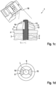
- ein erstes erfindungsgemäßes Befestigungssystem vor, während und nach der Montage des Befestigungsmittels in den Schnittdarstellungen 1a) bis 1c) und in einer Draufsicht 1d);
- Figur 2
- ein zweites erfindungsgemäßes Befestigungssystem vor und nach der Montage des Befestigungsmittels in den Schnittdarstellungen 2a) und 2b);
- Figur 3
- ein drittes erfindungsgemäßes Befestigungssystem vor und nach der Montage des Befestigungsmittels in den Schnittdarstellungen 3a) und 3b);
- Figur 4
- ein viertes erfindungsgemäßes Befestigungssystem vor und nach der Montage des Befestigungsmittels in den Schnittdarstellungen 4a) und 4b); und
- Figur 5
- ein fünftes erfindungsgemäßes Befestigungssystem vor und nach der Montage des Befestigungsmittels in den perspektivischen Darstellungen 5a) und 5b).
- Das in den Abbildungen a) bis d) der
Figur 1 dargestellte erste Befestigungssystem umfasst einen Anker als Befestigungsmittel 1, der in ein Bohrloch 2 in einem Verankerungsgrund 3 aus Beton eingebracht ist. Mit dem Befestigungsmittel 1 wird ein Anbauteil 4 am Verankerungsgrund 3 befestigt. Das Befestigungsmittel 1 ist in diesem Fall ein Spreizanker mit einem Ankerbolzen 5 mit einem Außengewinde 11, auf den eine Abreißmutter des Spreizankers als Abreißelement 6 aufgeschraubt wird, wodurch eine Unterlegscheibe 7 gegen das Anbauteil 4 gedrückt und somit das Anbauteil 4 gegen den Verankerungsgrund 3 verspannt wird (Figur 1b ). Das Abreißelement 6 ist einstückig aus Stahl hergestellt, mit zwei Teilen 8, 9, die miteinander über eine Solltrennstelle 10 verbunden sind. Die beiden Teile 8, 9 weisen eine gemeinsame Durchgangsbohrung 26 auf, in der im zweiten Teil 9 ein Gewinde 12 angeordnet ist, in diesem Fall ein Innengewinde, das sich, wie die Durchgangsbohrung 26, entlang einer Achse L des Gewindes 12 erstreckt. Das Gewinde 12 korrespondiert zu einem Außengewinde 11 des Ankerbolzens 5, auf das das Abreißelement 6 zur Montage auf den Ankerbolzen 5 aufgeschraubt werden kann. Der dem Anbauteil 4 abgewandte erste Teil 8 des Abreißelements 6 ist mutternartig ausgebildet und weist an seinem Umfang Schlüsselflächen als Werkzeugsitz 13 auf, an dem ein nicht dargestelltes Drehwerkzeug, beispielsweise ein Schraubenschlüssel oder eine Nuss eines Schlagschraubers, zur Montage angesetzt werden kann. Der dem Anbauteil 4 zugewandte zweite Teil 9 des Abreißelements 6 weist eine glockenförmige Umfangsfläche mit kreisförmigem Querschnitt auf, die sich zur Solltrennstelle 10 hin im Durchmesser verjüngt. Die Solltrennstelle 10 ist als V-förmige, in Umfangsrichtung um die Achse L umlaufende Nut ausgebildet, die in radialer Richtung so tief verläuft, dass in einer Draufsicht auf das Abreißelement 6, auf die dem Anbauteil 4 abgewandte Seite und in Richtung der Achse L, der erste Teil 8 des Abreißelements 6 das zweite Teil 9 in einem kreisringförmigen Abdeckbereich 14 abdeckt. Das erste Teil 8 ist somit ein Abdeckelement 20 für den Abdeckbereich 14. Im Abdeckbereich 14 ist ein Markiermittel 15 sowie ein Informationselement 16 angeordnet. Das Informationselement 16 umfasst einen Code 17, hier in Form eines optoelektronisch lesbaren DM-Codes. Das Informationselement 16 und das Markiermittel 15 befinden sich bezüglich der Achse L des Gewindes 12 an sich gegenüberliegenden Stellen des Abdeckbereichs 14. - Der Code 17 enthält Informationen zur Identifikation des Befestigungsmittels 1: Beispielsweise enthält der Code 17 einen Link zu einer Homepage, auf der Informationen zum Befestigungsmittel 1 zur Verfügung gestellt werden. Der Code 17 kann zudem, oder alternativ, eineindeutig für das Befestigungsmittel 1 sein. "Eineindeutig" meint, dass der Code 17 nur ein einziges Mal in derselben Form für genau das Befestigungsmittel 1 verwendet wird. So ist beispielsweise im Code 17 eine eineindeutige Seriennummer zur Identifikation des einen Befestigungsmittels 1 enthalten.
- Nach dem Ansetzen des als Abreißmutter ausgebildeten Abreißelements 6 am Außengewinde 11 des Ankerbolzens 5 (
Figur 1a ) wird das Abreißelement 6 auf das Außengewinde 11 aufgeschraubt. Dabei wird mit einem (nicht dargestellten) Drehwerkzeug ein Drehmoment über den Werkzeugsitz 13 auf das Abreißelement 6 aufgebracht und dieses vom ersten Teil 8 des Abreißelements 6 über die Solltrennstelle 10 auf das zweite Teil 9 des Abreißelements 6 übertragen, das das Gewinde 12 aufweist. Ist das Anbauteil 4 durch das Aufdrehen des Gewindes 12 des Abreißelements 6 auf das Außengewinde 11 des Ankerbolzens 5 planmäßig gegen den Verankerungsgrund 3 verspannt, so wird ein für diesen planmäßigen Befestigungszustand charakteristisches Installationsdrehmoment erreicht. Die Solltrennstelle 10 ist derart ausgelegt, dass sie beim Erreichen des Installationsdrehmoments nachgibt, sodass der erste Teil 8 des Abreißelements 6 vom aufgeschraubten zweiten Teil 9 abreißt und abgetrennt wird. Das Markiermittel 15 und das Informationselement 16 werden in diesem planmäßigen Befestigungszustand nun nicht mehr vom ersten Teil 8 abgedeckt. Entgegen dem ursprünglichen Ausgangszustand können das Markiermittel 15 und das Informationselement 16 nun gemeinsam, das heißt in einem Bild und zeitgleich von einem Sensor 18 erfasst werden (Figur 1c ). Im Ausführungsbeispiel ist der Sensor 18 ein optoelektronischer Sensor, nämlich die Kamera eines Mobiltelefons. InFigur 1d ) ist das Bild zu sehen, das der Sensor in diesem planmäßigen Befestigungszustand bei Draufsicht in Richtung der Achse L aufnehmen kann. - In einem Ausgangszustand, in dem der erste Teil 8 des Abreißelements 6 den Abdeckbereich 14 überdeckt, können das Markiermittel 15 und das Informationselement 16 dagegen nicht gemeinsam, das heißt zeitgleich und in einem Bild, erfasst werden. Der Sensor 18 kann im Ausgangszustand (
Figur 1a ) oder während der Montage das Informationselement 16 oder das Markiermittel 15 erfassen, aber nicht beide gemeinsam. - Das Markiermittel 15, beispielsweise eine farbige Markierung, enthält im Ausführungsbeispiel keinen Code oder eine zusätzliche Information. Das Markiermittel 15 ist ein Kontrollmittel zur Qualitätsprüfung der planmäßigen Befestigung. Erst wenn das Markiermittel 15 gemeinsam mit dem, im vorliegenden Fall eineindeutigen Informationselement 16 mit dem Sensor 18 erfasst werden kann, ist der Nachweis erbracht, dass das geforderte Qualitätsmerkmal, hier das Erreichen des erforderlichen Installationsdrehmoments, erreicht ist. Mit dem Sensor 18 kann dieses Qualitätsmerkmal dokumentiert werden, in dem das Markiermittel 15 und das Informationselement 16 mit der Kamera des Mobiltelefons gemeinsam erfasst und in einem Foto dokumentiert und dauerhaft gespeichert werden. Durch den eineindeutigen Code 17 ist die Zuordnung des Bilds zu dem jeweiligen Befestigungsmittel 1 dauerhaft gegeben. Der Code 17 ist auch auf dem Foto erkenn- und somit auslesbar.
- Die
Figuren 2 bis 5 zeigen weitere erfindungsgemäße Befestigungssysteme, die sich von dem ersten erfindungsgemäßen Befestigungssystem derFigur 1 insbesondere durch das verwendete Befestigungsmittel 1 unterscheiden. Um Wiederholungen zu vermeiden, wird nachfolgend nur auf die Unterschiede eingegangen. Der Übersichtlichkeit halber erhalten einander entsprechende Teile dieselben Bezugszeichen. - Die
Figur 2 zeigt als alternatives Befestigungsmittel 1 einen selbstschneidenden Hinterschnittanker. Dieser umfasst einen Ankerbolzen 5 und eine Hülse 19. In einem unverspreizten Ausgangszustand (Figur 2a ) verdeckt die Hülse 19 einen Code 17, hier ebenfalls ein Data-Matrix-Code, der am Ankerbolzen 5 axial zwischen zwei umlaufenden Ringen als Informationsmittel 16 angeordnet ist. Die beiden Ringe bilden das Markiermittel 15. Das hintere Ende der Hülse 19, die im unverspreizten Ausgangszustand über den Verankerungsgrund 3 übersteht, verdeckt den Code 17 und das Markiermittel 15 und hat somit die Funktion eines Abdeckelements 20. Informationselement 16 und Markiermittel 15 werden im Ausgangszustand von diesem Abdeckelement 20 vollständig abgedeckt, so dass sie mit dem Sensor 18 nicht erfassbar sind. Zum Überführen des Hinterschnittankers von diesem Ausgangszustand in einen planmäßigen Befestigungszustand, in dem der Hinterschnittanker als Befestigungsmittel 1 planmäßig in dem in diesem Fall dann hinterschnittenen Bohrloch 2 verankert ist (Figur 2b ), wird die Hülse 19 in der für selbstschneidende Hinterschnittanker bekannten Weise mit einem nicht dargestellten Werkzeug in das Bohrloch 2 hineingeschlagen, wodurch ein Spreizbereich der Hülse 19 aufspreizt, den Hinterschnitt des Bohrlochs 2 erstellt und den Hinterschnittanker im Bohrloch 2 planmäßig verankert, wasFigur 2b ) zeigt. In diesem planmäßigen Befestigungszustand ist die Hülse 19 so weit in das Bohrloch 2 hinein verschoben, dass sie sowohl die beiden Ringe als Markiermittel 15, wie auch den Code 17 als Informationselement 16 nicht mehr überdeckt und somit beide, Markiermittel 15 und Informationselement 16, mit dem Sensor 18 erfasst und dokumentiert werden können. Alternativ ist es auch möglich, dass der Code 17 sowohl Informationselement 16 als auch Markiermittel 15 darstellt, die beiden Ringe somit weggelassen werden können. In diesem Fall wäre das Markiermittel 15 mit dem Informationselement 16 identisch. Unabhängig davon, ob die Ringe oder der Code 17 das Markiermittel 15 bilden, zeigt das Markiermittel 15 als Kontrollmittel zur Qualitätsprüfung an, dass die Hülse 19 ausreichend weit in das Bohrloch 2 hinein verschoben und somit aufgespreizt worden ist. - Das dritte Ausführungsbeispiel der
Figur 3 entspricht dem zweiten Ausführungsbeispiel derFigur 2 mit dem Unterschied, dass zwischen den beiden Ringen des Markiermittels 15 eine Prüfziffer 21 statt des Codes 17 angeordnet ist. Die Prüfziffer bildet gemeinsam mit den Ringen das Markiermittel 15. Alternativ können auch in diesem Fall die beiden Ringe weggelassen werden, sodass nur die Prüfziffer 21 das Markiermittel 15 bildet. Die Prüfziffer 21 ist eine dreistellige Zahl, also ein mehrstelliges alphanumerisches Zeichen beziehungsweise ein alphanumerischer Code. Das Informationselement 16, auch ein DM-Code, ist an der hinteren Stirnfläche des Ankerbolzens 5 angeordnet. Somit kann das Informationselement 16 bereits im Ausgangszustand mit dem Sensor 18 erfasst werden, sodass ein Anwender beispielsweise das Informationselement 16 dazu verwenden kann, Informationen zur Montage des Befestigungsmittels 1 von einer durch Scannen des Codes 17 zugänglichen Website abzurufen. Dagegen ist nach der planmäßigen Montage des Hinterschnittankers sowohl das Markiermittel 15 als auch das Informationselement 16 erfassbar, wasFigur 3b ) zeigt. Die Prüfziffer 21 hat hier ebenfalls die Funktion eines Codes 17: Erst wenn die Prüfziffer 21 mit dem Sensor 18 vollständig als Zahl erfasst und ausgelesen werden kann, ist gewährleistet, dass der planmäßige Befestigungszustand erreicht ist. Ist die Prüfziffer 21 nicht auslesbar bedeutet dies, dass die Hülse 19 nicht weit genug verschoben wurde und der planmäßige Befestigungszustand noch nicht erreicht ist. Dabei kann der Code 17 eineindeutig für das Befestigungsmittel 1 sein. Der Code 17 beinhaltet dann Informationen zur Prüfziffer 21, die dem Befestigungsmittel 1 als eine definierte Zahl zugeordnet ist. Durch Scannen des DM-Codes mit dem Sensor 18 erhält der Anwender und/oder eine Verarbeitungssoftware die Prüfziffer 21 genannt, die dann mit der erfassten Prüfziffer 21 abgeglichen wird. Nach dem Erfassen der korrekten Prüfziffer 21 kann mit dem Sensor 18 ein Bild aufgenommen werden, auf dem der Code 17 und die Prüfziffer 21 gemeinsam abgebildet sind, so dass das Erreichen des planmäßigen Befestigungszustands dauerhaft und überprüfbar dokumentiert ist. - In
Figur 4 ist eine Abwandlung des aus derFigur 2 bekannten zweiten erfindungsgemäßen Befestigungssystems dargestellt. Dieses vierte erfindungsgemäße Befestigungssystem zeichnet sich durch ein Montagewerkzeug 22 aus. Das Montagewerkzeug 22 ist ein Hohlzylinder mit einer Öffnung 23, deren Ränder das Markiermittel 15 bilden beziehungsweise deren Ränder als Markiermittel 15 farbig oder auf andere Weise markiert sind. Zur Montage wird das Montagewerkzeug 22 auf den Ankerbolzen 5 aufgesetzt, sodass es an der Hülse 19 anliegt. Über das Montagewerkzeug 22 werden Schläge auf die Hülse 19 ausgeübt und die Hülse 19 dadurch in das Bohrloch 2 eingetrieben (Figur 4a ). Nach dem Erreichen des planmäßigen Befestigungszustands (Figur 4b ) ist das am Ankerbolzen 5 angeordnete Informationselement 16, hier ein DM-Code 17, durch die Öffnung 23 sichtbar. In diesem planmäßigen Befestigungszustand können somit das Markiermittel 15 und das Informationselement 16 gemeinsam mit dem Sensor 18 erfasst und das Erreichen des planmäßigen Befestigungszustands dokumentiert werden. -
Figur 5 zeigt ein fünftes Ausführungsbeispiel des erfindungsgemäßen Befestigungssystems. Das Befestigungsmittel 1 ist hier eine Gewindestange 24, die mit einer aushärtenden Klebermasse 25 in das Bohrloch 2 in dem Verankerungsgrund 3 eingeklebt ist. An der äußeren Stirnseite der Gewindestange 24 ist ein Code 17, auch hier ein DM-Code, als Informationselement 16 angeordnet. Die Klebermasse 25 ändert erfindungsgemäß beim Aushärten ihre Farbe, so dass sie im planmäßigen Befestigungszustand, in dem sie ausgehärtet ist, eine bestimmte, vordefinierte Farbe aufweist und somit als Markiermittel 15 wirkt. Die Klebermasse 25 wird durch die Farbänderung zum Markiermittel 15, das heißt, das Markiermittel 15 wird erst durch Farbänderung sichtbar. Der Sensor 18 und/oder das zugehörige Auswertprogramm ist derart eingestellt, dass er/es die Klebermasse 25 erst dann als Markiermittel 15 akzeptiert und erfasst, wenn es die vordefinierte Farbe angenommen hat (Figur 5b ). Davor ist die gemeinsame Erfassung von Informationselement 16 und Markiermittel 15 systembedingt nicht möglich. - Mit den beschriebenen erfindungsgemäßen Befestigungssystemen kann das Erreichen eines planmäßigen Befestigungszustands eindeutig erfasst und dokumentiert werden. Eine fehlerhafte Dokumentation durch die Erfassung von Markiermittel 15 und Informationselement 16 im Ausgangszustand oder während der Montage ist erfindungsgemäß ausgeschlossen.
-
- 1
- Befestigungsmittel
- 2
- Bohrloch
- 3
- Verankerungsgrund
- 4
- Anbauteil
- 5
- Ankerbolzen
- 6
- Abreißelement
- 7
- Unterlegscheibe
- 8
- erster Teil des Abreißelements 6
- 9
- zweiter Teil des Abreißelements 6
- 10
- Solltrennstelle
- 11
- Außengewinde
- 12
- Gewinde
- 13
- Werkzeugsitz
- 14
- Abdeckbereich
- 15
- Markiermittel
- 16
- Informationselement
- 17
- Code
- 18
- Sensor
- 19
- Hülse
- 20
- Abdeckelement
- 21
- Prüfziffer
- 22
- Montagewerkzeug
- 23
- Öffnung
- 24
- Gewindestange
- 25
- Klebermasse
- 26
- Durchgangsbohrung
- L
- Achse des Gewindes 12
Claims (15)
- Befestigungssystem zum planmäßigen Befestigen eines Befestigungsmittels (1), insbesondere zum planmäßigen Befestigen eines Ankers als Befestigungsmittel (1) in einem Bohrloch (2),wobei das Befestigungssystem das Befestigungsmittel (1) und einen vom Befestigungsmittel (1) separaten Sensor (18) umfasst,wobei das Befestigungsmittel (1) bei einer Montage von einem Ausgangszustand in einen planmäßigen Befestigungszustand überführbar ist, wobei das Befestigungssystem mindestens ein Markiermittel (15) und mindestens ein maschinenlesbares Informationselement (16) umfasst,dadurch gekennzeichnet,dass das Markiermittel (15) und das Informationselement (16) derart angeordnet sind, dass sie im planmäßigen Befestigungszustand, aber nicht vor und/oder während der Montage, gemeinsam mit dem Sensor (18) zum Nachweis der planmäßigen Befestigung erfassbar sind.
- Befestigungssystem nach Anspruch 1, dadurch gekennzeichnet, dass zumindest das Informationselement (16) einen optoelektronisch auslesbaren Code (17) zur Identifikation des Befestigungsmittels (1) umfasst oder ein derartiger Code (17) ist.
- Befestigungssystem nach einem der vorstehenden Ansprüche, dadurch gekennzeichnet, dass das Informationselement (16) und das Markiermittel (15) identisch und als ein Element ausgebildet sind.
- Befestigungssystem nach einem der vorstehenden Ansprüche, dadurch gekennzeichnet, dass das Informationselement (16) oder das Markiermittel (15) bereits im Ausgangszustand mit dem Sensor (18) erfassbar ist.
- Befestigungssystem nach einem der vorstehenden Ansprüche, dadurch gekennzeichnet, dass das Markiermittel (15) ein Kontrollmittel zur Qualitätsprüfung der planmäßigen Befestigung des Befestigungsmittels (1) ist.
- Befestigungssystem nach einem der vorstehenden Ansprüche, dadurch gekennzeichnet, dass das Befestigungsmittel (1) ein Abdeckelement (20) aufweist, das derart gestaltet ist, dass es vor und/oder während der Montage zumindest das Informationselement (16) oder das Markiermittel (15) derart abdeckt, dass sie nicht gemeinsam erfassbar sind, und dass das Abdeckelement (20) das Informationselement (16) und/oder das Markiermittel (15) beim Erreichen des Endzustands zum gemeinsamen Erfassen von Informationselement (16) und Markiermittel (15) mittels des Sensors (18) freigibt, insbesondere durch Verschieben, Verformen oder Abreißen des Abdeckelements (20) während der Montage.
- Befestigungssystem nach einem der vorstehenden Ansprüche, dadurch gekennzeichnet, dass das Befestigungssystem ein Abreißelement (6) umfasst, das aus zwei Teilen (8, 9) besteht, die mittels einer Solltrennstelle (10) verbunden sind, und dass das Informationselement (16) und das Markiermittel (15) gemeinsam an einem der beiden Teile (8, 9) angeordnet sind, insbesondere an sich bezüglich einer Achse (L) eines Gewindes (12) des Abreißelements (6) gegenüberliegenden Stellen.
- Befestigungssystem nach einem der vorstehenden Ansprüche, dadurch gekennzeichnet, dass das Befestigungssystem einen Spreizanker mit einem Ankerbolzen (5) und einer Hülse (19) umfasst, wobei zumindest das Informationselement (16) oder das Markiermittel (15) am Ankerbolzen (5) angeordnet ist.
- Befestigungssystem nach Anspruch 8, dadurch gekennzeichnet, dass das Markiermittel (15) an einem Montagewerkzeug (22) zur planmäßigen Montage des Befestigungsmittels (1) angeordnet ist.
- Befestigungssystem nach einem der vorstehenden Ansprüche, dadurch gekennzeichnet, dass das Markiermittel (15) mindestens ein alphanummerisches Zeichen umfasst.
- Befestigungssystem nach Anspruch 10, dadurch gekennzeichnet, dass das Markiermittel (15) ein mehrstelliger alphanummerischer Code, insbesondere eine Prüfziffer (21) ist.
- Befestigungssystem nach einem der vorstehenden Ansprüche, dadurch gekennzeichnet, dass das Informationselement (16) eineindeutig für das Befestigungsmittel (1) ist.
- Befestigungssystem nach einem der vorstehenden Ansprüche, dadurch gekennzeichnet, dass ein Markiermittel (15) derart gestaltet ist, dass es beim Erreichen des planmäßigen Befestigungszustands durch Farbänderung sichtbar wird.
- Verfahren zum planmäßigen Befestigen eines Befestigungsmittels (1) unter Verwendung eines Befestigungssystems nach einem der Ansprüche 1 bis 13, dadurch gekennzeichnet, dass nach der planmäßigen Montage des Befestigungsmittels (1) im planmäßigen Befestigungszustand das Markiermittel (15) und das Informationselement (16) zeitgleich und gemeinsam mit dem Sensor (18) erfasst werden.
- Befestigungsmittel (1), insbesondere ein Hinterschnittanker, zur Verwendung in einem Befestigungssystem gemäß Anspruch 10 oder 11 und/oder in einem Verfahren gemäß Anspruch 14, das mindestens ein maschinenlesbares Informationselement (16) und mindestens ein Markiermittel (15) aufweist, dadurch gekennzeichnet, dass das Markiermittel (15) mindestens ein alphanumerisches Zeichen umfasst oder ist.
Applications Claiming Priority (1)
| Application Number | Priority Date | Filing Date | Title |
|---|---|---|---|
| DE102022102385.0A DE102022102385A1 (de) | 2022-02-02 | 2022-02-02 | Befestigungssystem, Verfahren zum Befestigen eines Befestigungsmittels sowie Befestigungsmittel |
Publications (3)
| Publication Number | Publication Date |
|---|---|
| EP4269817A1 true EP4269817A1 (de) | 2023-11-01 |
| EP4269817C0 EP4269817C0 (de) | 2025-03-26 |
| EP4269817B1 EP4269817B1 (de) | 2025-03-26 |
Family
ID=84820198
Family Applications (1)
| Application Number | Title | Priority Date | Filing Date |
|---|---|---|---|
| EP23150227.9A Active EP4269817B1 (de) | 2022-02-02 | 2023-01-04 | Befestigungssystem, verfahren zum befestigen eines befestigungsmittels sowie befestigungsmittel |
Country Status (3)
| Country | Link |
|---|---|
| EP (1) | EP4269817B1 (de) |
| CN (1) | CN116538179A (de) |
| DE (1) | DE102022102385A1 (de) |
Citations (5)
| Publication number | Priority date | Publication date | Assignee | Title |
|---|---|---|---|---|
| DE2418598A1 (de) * | 1974-04-18 | 1975-10-30 | Upat Max Langensiepen Kg | Spreizanker |
| EP0943817A1 (de) * | 1998-03-16 | 1999-09-22 | SPS Technologies, Inc. | Verfahren zum Identifizieren einer Befestigungsvorrichtung |
| EP1176322A2 (de) * | 2000-07-26 | 2002-01-30 | Illinois Tool Works Inc. | Verfahren zum Anwenden von chemischen Befestigungskleber |
| WO2013113586A1 (de) | 2012-01-31 | 2013-08-08 | Hilti Aktiengesellschaft | Ankersystem, insbesondere hinterschnittankersystem |
| WO2018103805A1 (en) * | 2016-12-09 | 2018-06-14 | Vestas Wind Systems A/S | Pre-tensioning of bolts |
-
2022
- 2022-02-02 DE DE102022102385.0A patent/DE102022102385A1/de active Pending
-
2023
- 2023-01-04 EP EP23150227.9A patent/EP4269817B1/de active Active
- 2023-02-02 CN CN202310098799.1A patent/CN116538179A/zh active Pending
Patent Citations (5)
| Publication number | Priority date | Publication date | Assignee | Title |
|---|---|---|---|---|
| DE2418598A1 (de) * | 1974-04-18 | 1975-10-30 | Upat Max Langensiepen Kg | Spreizanker |
| EP0943817A1 (de) * | 1998-03-16 | 1999-09-22 | SPS Technologies, Inc. | Verfahren zum Identifizieren einer Befestigungsvorrichtung |
| EP1176322A2 (de) * | 2000-07-26 | 2002-01-30 | Illinois Tool Works Inc. | Verfahren zum Anwenden von chemischen Befestigungskleber |
| WO2013113586A1 (de) | 2012-01-31 | 2013-08-08 | Hilti Aktiengesellschaft | Ankersystem, insbesondere hinterschnittankersystem |
| WO2018103805A1 (en) * | 2016-12-09 | 2018-06-14 | Vestas Wind Systems A/S | Pre-tensioning of bolts |
Also Published As
| Publication number | Publication date |
|---|---|
| EP4269817C0 (de) | 2025-03-26 |
| DE102022102385A1 (de) | 2023-08-03 |
| CN116538179A (zh) | 2023-08-04 |
| EP4269817B1 (de) | 2025-03-26 |
Similar Documents
| Publication | Publication Date | Title |
|---|---|---|
| DE2005467C3 (de) | Rohrförmige Dübelhülse aus Kunststoff | |
| DE3833774C1 (de) | ||
| DE102004062391A1 (de) | Ein durch Nieten an ein Blechteil anbringbares Element sowie Zusammenbauteil und Verfahren zur Erzeugung des Zusammenbauteils | |
| DE102012201293A1 (de) | Ankersystem, insbesondere Hinterschnittankersystem | |
| EP3698924A2 (de) | Verfahren zum dokumentierten anziehen oder nachziehen einer schraubverbindung | |
| EP0676551B1 (de) | Befestigungselement zum Eintreiben in harte Aufnahmematerialien mittels pulverkraftbetriebener Setzgeräte | |
| DE2547634A1 (de) | Sicherheitsduebel | |
| EP0420797A2 (de) | Anschlagkörper für Betonschalungen | |
| DE4010476A1 (de) | An ankern, insbesondere injektionsankern fuer den bergbau oder dergleichen anzuordnende kontrollmutterverschraubung mit belastungsanzeigevorrichtung | |
| EP4269817B1 (de) | Befestigungssystem, verfahren zum befestigen eines befestigungsmittels sowie befestigungsmittel | |
| DE1809532A1 (de) | Fensterzarge und Verfahren sowie Vorrichtung zu ihrer Anbringung | |
| DE1450992A1 (de) | Duebel zur Befestigung von Gegenstaenden in Baustoffen | |
| DE19944217A1 (de) | Bolzenanker | |
| EP0724085A1 (de) | Formschlüssig setzbarer Hinterschnitt-Anker | |
| DE102019102133A1 (de) | Verfahren zum dokumentierten Anziehen oder Nachziehen einer Schraubverbindung | |
| DE102008020867A1 (de) | Befestigungselement | |
| EP0935075A1 (de) | Vorrichtung zum Befestigen eines Bauelementes in einem Abstand zu einem tragenden Bauteil | |
| EP1867805A2 (de) | Verfahren und Vorrichtung zur Montage von Bauteilen, insbesondere Dämmstoffplatten, an einer Wand | |
| EP4219863A1 (de) | Sperranker | |
| DE102022103656A1 (de) | Sensorische Vermessung verbundener Bauwerksegmente mittels Sensor an Befestigungselement | |
| DE102017127134A1 (de) | Kontrollelement mit Spannkraftkontrolle und Befestigungsanordnung | |
| EP0823562B1 (de) | Schlaganker zur Befestigung an dünnwandigen Betonteilen | |
| DE4016919C1 (de) | ||
| EP0578923B1 (de) | Verbindungsstift | |
| DE102020118602A1 (de) | Modulare Anschlageinheit sowie Verfahren zur Bildung einer derartigen Anschlageinheit |
Legal Events
| Date | Code | Title | Description |
|---|---|---|---|
| PUAI | Public reference made under article 153(3) epc to a published international application that has entered the european phase |
Free format text: ORIGINAL CODE: 0009012 |
|
| STAA | Information on the status of an ep patent application or granted ep patent |
Free format text: STATUS: THE APPLICATION HAS BEEN PUBLISHED |
|
| AK | Designated contracting states |
Kind code of ref document: A1 Designated state(s): AL AT BE BG CH CY CZ DE DK EE ES FI FR GB GR HR HU IE IS IT LI LT LU LV MC ME MK MT NL NO PL PT RO RS SE SI SK SM TR |
|
| STAA | Information on the status of an ep patent application or granted ep patent |
Free format text: STATUS: REQUEST FOR EXAMINATION WAS MADE |
|
| 17P | Request for examination filed |
Effective date: 20240410 |
|
| RBV | Designated contracting states (corrected) |
Designated state(s): AL AT BE BG CH CY CZ DE DK EE ES FI FR GB GR HR HU IE IS IT LI LT LU LV MC ME MK MT NL NO PL PT RO RS SE SI SK SM TR |
|
| REG | Reference to a national code |
Ref legal event code: R079 Free format text: PREVIOUS MAIN CLASS: F16B0013060000 Ipc: F16B0031020000 Ref country code: DE Ref legal event code: R079 Ref document number: 502023000708 Country of ref document: DE Free format text: PREVIOUS MAIN CLASS: F16B0013060000 Ipc: F16B0031020000 |
|
| GRAP | Despatch of communication of intention to grant a patent |
Free format text: ORIGINAL CODE: EPIDOSNIGR1 |
|
| STAA | Information on the status of an ep patent application or granted ep patent |
Free format text: STATUS: GRANT OF PATENT IS INTENDED |
|
| RIC1 | Information provided on ipc code assigned before grant |
Ipc: F16B 13/08 20060101ALI20241025BHEP Ipc: F16B 31/02 20060101AFI20241025BHEP |
|
| INTG | Intention to grant announced |
Effective date: 20241118 |
|
| GRAS | Grant fee paid |
Free format text: ORIGINAL CODE: EPIDOSNIGR3 |
|
| GRAA | (expected) grant |
Free format text: ORIGINAL CODE: 0009210 |
|
| STAA | Information on the status of an ep patent application or granted ep patent |
Free format text: STATUS: THE PATENT HAS BEEN GRANTED |
|
| AK | Designated contracting states |
Kind code of ref document: B1 Designated state(s): AL AT BE BG CH CY CZ DE DK EE ES FI FR GB GR HR HU IE IS IT LI LT LU LV MC ME MK MT NL NO PL PT RO RS SE SI SK SM TR |
|
| REG | Reference to a national code |
Ref country code: GB Ref legal event code: FG4D Free format text: NOT ENGLISH |
|
| REG | Reference to a national code |
Ref country code: CH Ref legal event code: EP |
|
| REG | Reference to a national code |
Ref country code: DE Ref legal event code: R096 Ref document number: 502023000708 Country of ref document: DE |
|
| REG | Reference to a national code |
Ref country code: IE Ref legal event code: FG4D Free format text: LANGUAGE OF EP DOCUMENT: GERMAN |
|
| U01 | Request for unitary effect filed |
Effective date: 20250326 |
|
| U07 | Unitary effect registered |
Designated state(s): AT BE BG DE DK EE FI FR IT LT LU LV MT NL PT RO SE SI Effective date: 20250401 |
|
| PG25 | Lapsed in a contracting state [announced via postgrant information from national office to epo] |
Ref country code: RS Free format text: LAPSE BECAUSE OF FAILURE TO SUBMIT A TRANSLATION OF THE DESCRIPTION OR TO PAY THE FEE WITHIN THE PRESCRIBED TIME-LIMIT Effective date: 20250626 |
|
| PG25 | Lapsed in a contracting state [announced via postgrant information from national office to epo] |
Ref country code: NO Free format text: LAPSE BECAUSE OF FAILURE TO SUBMIT A TRANSLATION OF THE DESCRIPTION OR TO PAY THE FEE WITHIN THE PRESCRIBED TIME-LIMIT Effective date: 20250626 |
|
| PG25 | Lapsed in a contracting state [announced via postgrant information from national office to epo] |
Ref country code: HR Free format text: LAPSE BECAUSE OF FAILURE TO SUBMIT A TRANSLATION OF THE DESCRIPTION OR TO PAY THE FEE WITHIN THE PRESCRIBED TIME-LIMIT Effective date: 20250326 |
|
| PG25 | Lapsed in a contracting state [announced via postgrant information from national office to epo] |
Ref country code: GR Free format text: LAPSE BECAUSE OF FAILURE TO SUBMIT A TRANSLATION OF THE DESCRIPTION OR TO PAY THE FEE WITHIN THE PRESCRIBED TIME-LIMIT Effective date: 20250627 |
|
| PG25 | Lapsed in a contracting state [announced via postgrant information from national office to epo] |
Ref country code: SM Free format text: LAPSE BECAUSE OF FAILURE TO SUBMIT A TRANSLATION OF THE DESCRIPTION OR TO PAY THE FEE WITHIN THE PRESCRIBED TIME-LIMIT Effective date: 20250326 |
|
| PG25 | Lapsed in a contracting state [announced via postgrant information from national office to epo] |
Ref country code: ES Free format text: LAPSE BECAUSE OF FAILURE TO SUBMIT A TRANSLATION OF THE DESCRIPTION OR TO PAY THE FEE WITHIN THE PRESCRIBED TIME-LIMIT Effective date: 20250326 |
|
| PG25 | Lapsed in a contracting state [announced via postgrant information from national office to epo] |
Ref country code: PL Free format text: LAPSE BECAUSE OF FAILURE TO SUBMIT A TRANSLATION OF THE DESCRIPTION OR TO PAY THE FEE WITHIN THE PRESCRIBED TIME-LIMIT Effective date: 20250326 |
|
| PG25 | Lapsed in a contracting state [announced via postgrant information from national office to epo] |
Ref country code: SK Free format text: LAPSE BECAUSE OF FAILURE TO SUBMIT A TRANSLATION OF THE DESCRIPTION OR TO PAY THE FEE WITHIN THE PRESCRIBED TIME-LIMIT Effective date: 20250326 |
|
| PG25 | Lapsed in a contracting state [announced via postgrant information from national office to epo] |
Ref country code: IS Free format text: LAPSE BECAUSE OF FAILURE TO SUBMIT A TRANSLATION OF THE DESCRIPTION OR TO PAY THE FEE WITHIN THE PRESCRIBED TIME-LIMIT Effective date: 20250726 |
|
| PG25 | Lapsed in a contracting state [announced via postgrant information from national office to epo] |
Ref country code: CZ Free format text: LAPSE BECAUSE OF FAILURE TO SUBMIT A TRANSLATION OF THE DESCRIPTION OR TO PAY THE FEE WITHIN THE PRESCRIBED TIME-LIMIT Effective date: 20250326 |
|
| U20 | Renewal fee for the european patent with unitary effect paid |
Year of fee payment: 4 Effective date: 20260101 |
|
| PLBE | No opposition filed within time limit |
Free format text: ORIGINAL CODE: 0009261 |
|
| STAA | Information on the status of an ep patent application or granted ep patent |
Free format text: STATUS: NO OPPOSITION FILED WITHIN TIME LIMIT |
|
| REG | Reference to a national code |
Ref country code: CH Ref legal event code: L10 Free format text: ST27 STATUS EVENT CODE: U-0-0-L10-L00 (AS PROVIDED BY THE NATIONAL OFFICE) Effective date: 20260211 |
|
| 26N | No opposition filed |
Effective date: 20260105 |