EP4267872B1 - Ventilvorrichtung - Google Patents
Ventilvorrichtung Download PDFInfo
- Publication number
- EP4267872B1 EP4267872B1 EP22702952.7A EP22702952A EP4267872B1 EP 4267872 B1 EP4267872 B1 EP 4267872B1 EP 22702952 A EP22702952 A EP 22702952A EP 4267872 B1 EP4267872 B1 EP 4267872B1
- Authority
- EP
- European Patent Office
- Prior art keywords
- drive
- valve
- motor
- housing
- gear
- Prior art date
- Legal status (The legal status is an assumption and is not a legal conclusion. Google has not performed a legal analysis and makes no representation as to the accuracy of the status listed.)
- Active
Links
Images




Classifications
-
- F—MECHANICAL ENGINEERING; LIGHTING; HEATING; WEAPONS; BLASTING
- F16—ENGINEERING ELEMENTS AND UNITS; GENERAL MEASURES FOR PRODUCING AND MAINTAINING EFFECTIVE FUNCTIONING OF MACHINES OR INSTALLATIONS; THERMAL INSULATION IN GENERAL
- F16K—VALVES; TAPS; COCKS; ACTUATING-FLOATS; DEVICES FOR VENTING OR AERATING
- F16K31/00—Actuating devices; Operating means; Releasing devices
- F16K31/02—Actuating devices; Operating means; Releasing devices electric; magnetic
- F16K31/04—Actuating devices; Operating means; Releasing devices electric; magnetic using a motor
- F16K31/046—Actuating devices; Operating means; Releasing devices electric; magnetic using a motor with electric means, e.g. electric switches, to control the motor or to control a clutch between the valve and the motor
-
- F—MECHANICAL ENGINEERING; LIGHTING; HEATING; WEAPONS; BLASTING
- F15—FLUID-PRESSURE ACTUATORS; HYDRAULICS OR PNEUMATICS IN GENERAL
- F15B—SYSTEMS ACTING BY MEANS OF FLUIDS IN GENERAL; FLUID-PRESSURE ACTUATORS, e.g. SERVOMOTORS; DETAILS OF FLUID-PRESSURE SYSTEMS, NOT OTHERWISE PROVIDED FOR
- F15B13/00—Details of servomotor systems ; Valves for servomotor systems
- F15B13/02—Fluid distribution or supply devices characterised by their adaptation to the control of servomotors
- F15B13/04—Fluid distribution or supply devices characterised by their adaptation to the control of servomotors for use with a single servomotor
- F15B13/0401—Valve members; Fluid interconnections therefor
- F15B13/0402—Valve members; Fluid interconnections therefor for linearly sliding valves, e.g. spool valves
-
- F—MECHANICAL ENGINEERING; LIGHTING; HEATING; WEAPONS; BLASTING
- F15—FLUID-PRESSURE ACTUATORS; HYDRAULICS OR PNEUMATICS IN GENERAL
- F15B—SYSTEMS ACTING BY MEANS OF FLUIDS IN GENERAL; FLUID-PRESSURE ACTUATORS, e.g. SERVOMOTORS; DETAILS OF FLUID-PRESSURE SYSTEMS, NOT OTHERWISE PROVIDED FOR
- F15B13/00—Details of servomotor systems ; Valves for servomotor systems
- F15B13/02—Fluid distribution or supply devices characterised by their adaptation to the control of servomotors
- F15B13/04—Fluid distribution or supply devices characterised by their adaptation to the control of servomotors for use with a single servomotor
- F15B13/0401—Valve members; Fluid interconnections therefor
- F15B13/0406—Valve members; Fluid interconnections therefor for rotary valves
-
- F—MECHANICAL ENGINEERING; LIGHTING; HEATING; WEAPONS; BLASTING
- F16—ENGINEERING ELEMENTS AND UNITS; GENERAL MEASURES FOR PRODUCING AND MAINTAINING EFFECTIVE FUNCTIONING OF MACHINES OR INSTALLATIONS; THERMAL INSULATION IN GENERAL
- F16K—VALVES; TAPS; COCKS; ACTUATING-FLOATS; DEVICES FOR VENTING OR AERATING
- F16K11/00—Multiple-way valves, e.g. mixing valves; Pipe fittings incorporating such valves
- F16K11/02—Multiple-way valves, e.g. mixing valves; Pipe fittings incorporating such valves with all movable sealing faces moving as one unit
- F16K11/06—Multiple-way valves, e.g. mixing valves; Pipe fittings incorporating such valves with all movable sealing faces moving as one unit comprising only sliding valves, i.e. sliding closure elements
- F16K11/065—Multiple-way valves, e.g. mixing valves; Pipe fittings incorporating such valves with all movable sealing faces moving as one unit comprising only sliding valves, i.e. sliding closure elements with linearly sliding closure members
- F16K11/07—Multiple-way valves, e.g. mixing valves; Pipe fittings incorporating such valves with all movable sealing faces moving as one unit comprising only sliding valves, i.e. sliding closure elements with linearly sliding closure members with cylindrical slides
-
- F—MECHANICAL ENGINEERING; LIGHTING; HEATING; WEAPONS; BLASTING
- F16—ENGINEERING ELEMENTS AND UNITS; GENERAL MEASURES FOR PRODUCING AND MAINTAINING EFFECTIVE FUNCTIONING OF MACHINES OR INSTALLATIONS; THERMAL INSULATION IN GENERAL
- F16K—VALVES; TAPS; COCKS; ACTUATING-FLOATS; DEVICES FOR VENTING OR AERATING
- F16K31/00—Actuating devices; Operating means; Releasing devices
- F16K31/02—Actuating devices; Operating means; Releasing devices electric; magnetic
- F16K31/04—Actuating devices; Operating means; Releasing devices electric; magnetic using a motor
-
- F—MECHANICAL ENGINEERING; LIGHTING; HEATING; WEAPONS; BLASTING
- F16—ENGINEERING ELEMENTS AND UNITS; GENERAL MEASURES FOR PRODUCING AND MAINTAINING EFFECTIVE FUNCTIONING OF MACHINES OR INSTALLATIONS; THERMAL INSULATION IN GENERAL
- F16K—VALVES; TAPS; COCKS; ACTUATING-FLOATS; DEVICES FOR VENTING OR AERATING
- F16K31/00—Actuating devices; Operating means; Releasing devices
- F16K31/44—Mechanical actuating means
- F16K31/53—Mechanical actuating means with toothed gearing
-
- F—MECHANICAL ENGINEERING; LIGHTING; HEATING; WEAPONS; BLASTING
- F16—ENGINEERING ELEMENTS AND UNITS; GENERAL MEASURES FOR PRODUCING AND MAINTAINING EFFECTIVE FUNCTIONING OF MACHINES OR INSTALLATIONS; THERMAL INSULATION IN GENERAL
- F16K—VALVES; TAPS; COCKS; ACTUATING-FLOATS; DEVICES FOR VENTING OR AERATING
- F16K31/00—Actuating devices; Operating means; Releasing devices
- F16K31/44—Mechanical actuating means
- F16K31/53—Mechanical actuating means with toothed gearing
- F16K31/54—Mechanical actuating means with toothed gearing with pinion and rack
-
- F—MECHANICAL ENGINEERING; LIGHTING; HEATING; WEAPONS; BLASTING
- F16—ENGINEERING ELEMENTS AND UNITS; GENERAL MEASURES FOR PRODUCING AND MAINTAINING EFFECTIVE FUNCTIONING OF MACHINES OR INSTALLATIONS; THERMAL INSULATION IN GENERAL
- F16K—VALVES; TAPS; COCKS; ACTUATING-FLOATS; DEVICES FOR VENTING OR AERATING
- F16K37/00—Special means in or on valves or other cut-off apparatus for indicating or recording operation thereof, or for enabling an alarm to be given
- F16K37/0025—Electrical or magnetic means
- F16K37/0033—Electrical or magnetic means using a permanent magnet, e.g. in combination with a reed relays
-
- F—MECHANICAL ENGINEERING; LIGHTING; HEATING; WEAPONS; BLASTING
- F15—FLUID-PRESSURE ACTUATORS; HYDRAULICS OR PNEUMATICS IN GENERAL
- F15B—SYSTEMS ACTING BY MEANS OF FLUIDS IN GENERAL; FLUID-PRESSURE ACTUATORS, e.g. SERVOMOTORS; DETAILS OF FLUID-PRESSURE SYSTEMS, NOT OTHERWISE PROVIDED FOR
- F15B13/00—Details of servomotor systems ; Valves for servomotor systems
- F15B13/02—Fluid distribution or supply devices characterised by their adaptation to the control of servomotors
- F15B13/04—Fluid distribution or supply devices characterised by their adaptation to the control of servomotors for use with a single servomotor
- F15B13/044—Fluid distribution or supply devices characterised by their adaptation to the control of servomotors for use with a single servomotor operated by electrically-controlled means, e.g. solenoids, torque-motors
- F15B13/0444—Fluid distribution or supply devices characterised by their adaptation to the control of servomotors for use with a single servomotor operated by electrically-controlled means, e.g. solenoids, torque-motors with rotary electric motor
-
- F—MECHANICAL ENGINEERING; LIGHTING; HEATING; WEAPONS; BLASTING
- F15—FLUID-PRESSURE ACTUATORS; HYDRAULICS OR PNEUMATICS IN GENERAL
- F15B—SYSTEMS ACTING BY MEANS OF FLUIDS IN GENERAL; FLUID-PRESSURE ACTUATORS, e.g. SERVOMOTORS; DETAILS OF FLUID-PRESSURE SYSTEMS, NOT OTHERWISE PROVIDED FOR
- F15B13/00—Details of servomotor systems ; Valves for servomotor systems
- F15B13/02—Fluid distribution or supply devices characterised by their adaptation to the control of servomotors
- F15B13/04—Fluid distribution or supply devices characterised by their adaptation to the control of servomotors for use with a single servomotor
- F15B13/0401—Valve members; Fluid interconnections therefor
- F15B2013/0409—Position sensing or feedback of the valve member
Definitions
- the invention relates to a valve device having the features in the preamble of claim 1.
- a valve device is provided by EN 10 2015 015 685 A1 known.
- An electric motor is provided for controlling the valve piston in this way, with a rotor and a stator with stator coils, whereby the drive axis of the electric motor intersects the travel axis of the valve piston at a point or is arranged offset from this point by a maximum of an average half diameter of a fictitious circle through the centers of the stator coils.
- an overall narrow segment design can be achieved for the valve device as a whole, which plays a role when a large number of such valves are to be attached to third-party components, such as components of work machines and commercial vehicles, in a side-by-side arrangement.
- electronically controlled electric motors can be used to advantage for this known solution, and the disadvantages of the otherwise usual stepper motors of the low dynamic torque and the strong, required reduction with correspondingly strong self-locking are thus eliminated.
- the EN 10 2018 207 927 A1 describes a valve device according to the preamble of claim 1, consisting of at least one valve piston arranged to be longitudinally movable in a valve housing, which, by means of a drive and associated drive train, connects or separates individual fluid connection points present in the valve housing in a fluid-conducting manner, wherein the respective position of the drive train and thus the respective position of the valve piston in the valve housing is monitored by means of a sensor device, wherein the drive is an electric motor, wherein the drive train has at least one motor shaft that can be driven by the electric motor, and wherein the sensor device has a sensor that monitors the motor shaft.
- the invention is based on the object of further improving the valve device while retaining the described advantages in such a way that reliable position monitoring for the valve piston of the valve device is maintained.
- a valve device having the features of patent claim 1 in its entirety solves this problem.
- the motor shaft opens with its one end into a gear which, with a gear shaft, controls a drive pinion which meshes with a rack which cooperates with the valve piston, and that the sensor device has a sensor which monitors the gear shaft.
- the respective position of the drive train and thus the respective position of the valve piston in the valve housing is monitored by means of a sensor device, the respective position of the valve piston in the valve housing can be monitored in a functionally reliable manner so that malfunctions are excluded.
- Such precise detection of the absolute position of the valve piston or the control slide is extremely advantageous for the purposes of functionally reliable systems in order to increase the so-called diagnostic coverage for fluid valves, especially hydraulic valves.
- the sensor device can be connected to appropriate evaluation electronics, which are integrated into the valve device as a whole and allow a direct display of the system status of the valve device, for example by integrating a status LED display in housing parts of the valve device. Furthermore, measured values from the sensor device can be passed on to a central control and evaluation unit as part of an electrical longitudinal chain with several interconnected valve devices, for example as part of a centrally organized machine control system.
- the drive is an electric motor and the drive train has at least one motor shaft that can be driven by the electric motor and that has one end that leads into a gear that uses a gear shaft to control a drive pinion that meshes with a rack that interacts with the valve piston. Due to the gear, the high drive speed of the electric motor for the drive pinion that interacts with the rack of the valve piston can be reduced accordingly in order to enable reliable actuation of the valve piston, which is helped by the fact that the drive train is divided into a motor shaft and a gear shaft. For reliable operation, it is advantageous that the motor shaft is connected to the other end, facing away from the gear, via the electric motor is rotatably mounted in a drive housing.
- the sensor used in each case is a so-called Hall sensor, which is housed in the drive housing and interacts with the motor or gear shaft, which each have a permanent magnet for tapping the corresponding measured value.
- a planetary gear preferably a two-stage planetary gear, is used as the gear for reducing the engine speed for driving the drive pinion for the rack and pinion drive of the valve piston between the engine and gear shaft.
- valve housing and the drive housing represent independent housing units that can be coupled to one another, so that, if necessary, valve housings already delivered with fluid connection points and valve pistons or valve slides can be retrofitted with a corresponding drive together with electronic control monitoring.
- valve device according to the invention is explained in more detail using the example of a directional valve in the form of a so-called slide valve. If terms such as “top”, “top” and “bottom” as well as “bottom” are used, these details refer to a normal installation position as shown in the figures.
- valve housing 4 has pairs of longitudinal sides 8 and end faces 10, 12 that are opposite one another.
- the valve housing 4 also has an upper side 14 and a lower side 16.
- the lower side 16, as shown in the Fig.1 is shown only broken off for the sake of simplicity.
- the utility connections A, B open out of the valve housing 4 along the top 14 and the two tank connections T, which accommodate the pressure supply connection P between them, open along the bottom 16. All of the connections A, B, P, T represent the fluid connection points of the valve housing 4.
- valve device has the Fig.1 nor an emergency actuation 22, which interacts with the valve piston 2 and, for example, returns the valve piston 2 to its Fig.1 shown initial or neutral position is possible.
- a stroke length limiter 24 with two adjusting screws 26, 28 is provided for the valve piston 2. The latter design is also common in valve devices of this type, so it will not be discussed in more detail here.
- a drive housing 30 is connected to the right-hand end face 10 of the valve housing 4, which has a
- the drive train 32 includes, among other things, an electric motor 34 as a drive, which is preferably designed as a brushless DC motor.
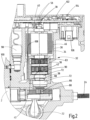
- the details of the electric motor 34 in question are described in particular in the Fig.4
- On the underside or at the lower end of the electric motor 34 there is a gear 36, in particular in the form of a reduction gear.
- the gear 36 in question as a two-stage planetary gear is particularly in the Fig.5
- all movable parts of the drive train 32 in the drive housing 30 run under oil.
- sensor device 38 is present, with two sensors in the form of an upper Hall sensor 40 and in the form of a lower Hall sensor 42.
- the relevant sensor device 38 with its two Hall sensors 40, 42 allows the respective position monitoring for parts of the drive train 32 and thus allows a direct conclusion to be drawn about the respective position of the valve piston 2 in the valve housing 4.
- the drive train 32 has a motor shaft 44 that can be driven by the electric motor 34.
- the motor shaft 44 opens out of the housing of the electric motor 34 on both of its free sides and is rotatably guided in its end area in conventional bearing points 48.
- the electric motor 34 accommodated in the motor housing 46 has a rotor 52 that is rotatably guided in stator coils 50 and is held rotatably in an axial position in the motor housing 46 by means of spring preload of a compression spring 54 and thus transmits its drive torque to the motor shaft 44.
- the box-shaped motor housing 46 is integrated in the drive housing 30.
- the motor shaft 44 points towards the Fig.4 seen at its upper end a permanent magnet 56 and furthermore one can see in the upper area connection points 58 in the form of a plug part for the purpose of supplying power to the stator coils 50.
- the motor shaft 44 is provided with a type of spline shaft toothing 60 for the purpose of engaging in an associated receiving point 62 of an upper, first planetary stage 63 of the two-stage planetary gear 36.
- the upper permanent magnet 56 interacts with the upper Hall sensor 40 which is stationary in the drive housing 30.
- the gear 36 opens at its lower end into a gear shaft 64, at the lower end of which a drive pinion 66 is arranged, which, as shown in the illustration, is Fig.1 and 2 meshes with a rack 68, on the left side of which the valve piston 2 is connected, preferably in a one-piece design with the rack 68.
- the gear shaft 64 is guided in the gear housing 70 with the gear 36 by means of two bearings 72 so that it can rotate but cannot be moved axially.
- the gear shaft 64 is in turn fixed to a second, lower planetary stage 75 of the planetary gear 36 on the output side by means of a spline connection 74.
- the spline connection 74 in question projects according to the illustration after the Fig.5 into a central planet carrier 76 of the gear box 36, but without exerting any torque transmission in this area. Between the two bearing points 72 there is another permanent magnet 78, which cooperates in a rotationally fixed manner with the gear box shaft 64 and the lower Hall sensor 42 (see Fig. 2 ) is controlled.
- the two-stage planetary gear 36 has the first planetary stage 63 with three planetary gears 80, which rotate around a sun gear 82, which engages in the manner of a spline shaft toothing 60 in the receiving point 62 of the first planetary gear stage 63.
- the three planetary gears 80 with the same toothing are guided rotatably on the first, upper planet carrier 76 via axes 84.
- the three planetary gears 80 mesh on the outer circumference according to the representation after the Fig.7 in a ring gear 86, which is fixedly connected to the gear casing 88.
- the individual axes 84 pass through the upper planet carrier 76 and are guided to a lower planet carrier 90.
- three further planet gears 92 are rotatably guided on the axes 84 coaxially to the three planet gears 80 and extend between the upper planet carrier 76 and the lower planet carrier 90.
- the three further planet gears 92 each have a greater number of teeth than a planet gear 80 of the first planetary stage 63 above.
- the three further planet gears 92 form the second planetary stage 75 of the gear 36 with their second planet carrier 90 and the middle sun gear 94, which in this respect also forms a type of splined shaft connection 74 with the planet gears 92.
- both the first ring gear 86 and the second ring gear 96 are part of the gear casing 88, which, as shown in the illustration, Fig.2 which in turn is an integral part of the drive housing 30.
- the associated sun gear 82 drives the three rotating planetary gears 80 and these take the three other planetary gears 92 with them in the same direction of rotation via their axes 84, whereby these pass on their corresponding rotational movement to the middle sun gear 94 of the second planetary stage 75 on the output side, which, connected to the gear shaft 64, drives the drive pinion 66 for the rack drive of the valve piston 2.
- the respective planetary gears 80, 92 run on their associated ring gears 86, 96 on the inside of the gear casing 88. In this way, very high speeds of the electric motor can be reduced to low drive speeds for the drive pinion 66.
- a pressure sensor 98 in the drive housing 30 at the edge, which monitors the fluid pressure in the area of the right pressure relief valve 20 via a transverse channel 100.
- the top of the drive housing is closed off by a cover part with a circuit board 102 accommodated therein.
- the circuit board 102 mentioned is advantageously accommodated horizontally above the electric motor 34, so that the position measurement can be carried out via the upper Hall sensor 40 in a space-saving manner, namely via the permanent magnet 78 sitting on the motor shaft 44. Furthermore, this enables a simple connection of the external plug contacts in the form of the connection points 58, which can be done within the framework of easily implemented press-in contacts in the circuit board 102.
- the circuit board 102 has an LED display 104 exposed to the outside, via which the operating state for the entire valve device can be seen.
- valve devices arranged one behind the other can be connected in a type of longitudinal chain (not shown) as shown in the illustration according to the Fig.1 in segmental design, centrally monitored and controlled by a machine control system.
- the two Hall sensors 40, 42 are connected to each other via a common electrical supply line 108.
Landscapes
- Engineering & Computer Science (AREA)
- General Engineering & Computer Science (AREA)
- Mechanical Engineering (AREA)
- Physics & Mathematics (AREA)
- Fluid Mechanics (AREA)
- Indication Of The Valve Opening Or Closing Status (AREA)
Description
- Die Erfindung betrifft eine Ventilvorrichtung mit den Merkmalen im Oberbegriff von Anspruch 1.
- Eine Ventilvorrichtung ist durch
DE 10 2015 015 685 A1 bekannt. Zum dahingehenden Ansteuern des Ventilkolbens ist ein Elektromotor vorgesehen, mit einem Rotor und einem Stator mit Statorspulen, wobei die Antriebsachse des Elektromotors die Verfahrachse des Ventilkolbens in einem Punkt schneidet oder um maximal einen durchschnittlichen halben Durchmesser eines fiktiven Kreises durch die Mittelpunkte der Statorspulen versetzt zu diesem Punkt angeordnet ist. Bei dieser Art der Motoranordnung lässt sich eine insgesamt schmale Segmentbauweise für die Ventilvorrichtung als Ganzes erreichen, was eine Rolle spielt, wenn eine Vielzahl solcher Ventile in Nebeneinanderanordnung an Drittbauteilen, wie Bauteilen von Arbeitsmaschinen und Nutzfahrzeugen, anzubringen sind. Ferner lassen sich für diese bekannte Lösung mit Vorteil elektronisch geregelte Elektromotoren einsetzen und die bei den ansonst üblichen Schrittmotoren gegebenen Nachteile des geringen dynamischen Drehmomentes sowie der starken, erforderlichen Untersetzung mit entsprechend starker Selbsthemmung kommen dadurch in Wegfall. - Die
DE 10 2018 207 927 A1 beschreibt eine Ventilvorrichtung, gemäß der Präambel von Anspruch 1, bestehend aus mindestens einem, in einem Ventilgehäuse längsverfahrbar angeordneten Ventilkolben, der mittels eines Antriebs nebst zugehörigem Antriebsstrang bewegt einzelne im Ventilgehäuse vorhandene Fluidanschlussstellen miteinander fluidführend verbindet oder voneinander trennt, wobei mittels einer Sensoreinrichtung die jeweilige Position des Antriebsstranges und damit die jeweilige Position des Ventilkolbens im Ventilgehäuse überwacht ist, wobei der Antrieb ein Elektromotor ist, wobei der Antriebsstrang zumindest eine von dem Elektromotor antreibbare Motorwelle aufweist, und wobei die Sensoreinrichtung einen Sensor aufweist, der die Motorwelle überwacht. - Ausgehend von diesem Stand der Technik liegt der Erfindung die Aufgabe zugrunde, unter Beibehalten der beschriebenen Vorteile die Ventilvorrichtung dahingehend weiter zu verbessern, dass eine sichere Positionsüberwachung für den Ventilkolben der Ventilvorrichtung erhalten ist.
- Eine dahingehende Aufgabe löst eine Ventilvorrichtung mit den Merkmalen des Patentanspruches 1 in seiner Gesamtheit.
- Gemäß dem Kennzeichen von Anspruch 1 ist vorgesehen, dass die Motorwelle mit ihrem einen Ende in ein Getriebe ausmündet, das mit einer Getriebewelle ein Antriebsritzel ansteuert, das mit einer Zahnstange kämmt, die mit dem Ventilkolben zusammenwirkt, und dass die Sensoreinrichtung einen Sensor aufweist, der die Getriebewelle überwacht.
- Dergestalt ist eine Redundanz für die Sensoreinrichtung erreicht und der Sensor, der die Position der Getriebewelle überwacht, ermöglicht eine Detektierung einer Absolut-Position für den Ventilkolben im zugehörigen Ventilgehäuse, was den Diagnose-Deckungsgrad dadurch erhöht, dass redundante Sensoren verwendet sind, und zwar an der Motorwelle sowie an der Getriebewelle.
- Dadurch, dass mittels einer Sensoreinrichtung die jeweilige Position des Antriebsstranges und damit die jeweilige Position des Ventilkolbens im Ventilgehäuse überwacht ist, lässt sich in funktionssicherer Weise die jeweilige Stellung des Ventilkolbens im Ventilgehäuse überwachen, so dass Fehlfunktionen ausgeschlossen sind. Eine dahingehend genaue Erfassung der Absolut-Position des Ventilkolbens respektive des Steuerschiebers ist für Zwecke funktionalsicherer Systeme ausgesprochen vorteilhaft, um den sogenannten Diagnose-Deckungsgrad für Fluid-Ventile, insbesondere Hydraulik-Ventile, zu vergrößern.
- Von großem Vorteil ist dabei weiter, dass die Sensoreinrichtung an eine entsprechende Auswertelektronik angeschlossen werden kann, die in der Ventilvorrichtung als Ganzes integriert, direkt eine Anzeige über den Systemzustand der Ventilvorrichtung zulässt, beispielsweise in dem eine Status-LED-Anzeige in Gehäuseteilen der Ventilvorrichtung integriert ist. Ferner lassen sich Messwerte der Sensoreinrichtung im Rahmen einer elektrischen Längsverkettung mit mehreren miteinander verbundenen Ventilvorrichtungen an eine zentrale Steuer- und Auswerteeinheit weitergeben, beispielsweise im Rahmen einer zentralorganisierten Maschinensteuerung.
- Der Antrieb ist ein Elektromotor und der Antriebsstrang weist zumindest eine von dem Elektromotor antreibbare Motorwelle auf, die mit ihrem einen Ende in ein Getriebe ausmündet, das mit einer Getriebewelle ein Antriebsritzel ansteuert, das mit einer Zahnstange kämmt, die mit dem Ventilkolben zusammenwirkt. Aufgrund des Getriebes lässt sich die hohe Antriebsdrehzahl des Elektromotors für das Antriebsritzel, das mit der Zahnstange des Ventilkolbens zusammenwirkt, entsprechend untersetzen, um dergestalt eine sichere Betätigung für den Ventilkolben zu ermöglichen, wozu mitbeiträgt, dass der Antriebsstrang in eine Motorwelle und eine Getriebewelle unterteilt ist. Für einen funktionssicheren Betrieb ist dabei von Vorteil, dass die Motowelle an ihrem anderen, dem Getriebe abgekehrten Ende, über den Elektromotor vorstehend, drehbar in einem Antriebsgehäuse gelagert ist.
- Der jeweils zum Einsatz kommende Sensor ist ein sogenannter Hall-Sensor, der im Antriebsgehäuse aufgenommen ist und der mit der Motor- bzw. der Getriebewelle zusammenwirkt, die für einen entsprechenden Messwertabgriff jeweils einen Permanentmagneten aufweisen.
- In bevorzugter Weise ist für die Untersetzung der Motordrehzahl zwecks Antrieb des Antriebsritzels für den Zahnstangentrieb des Ventilkolbens zwischen Motor- und Getriebewelle als Getriebe ein Planetenradgetriebe, vorzugsweise ein zweistufiges Planetenradgetriebe, eingesetzt.
- Bei einer bevorzugten Ausführungsform der erfindungsgemäßen Ventilvorrichtung ist vorgesehen, dass der Elektromotor ein bürstenloser Gleichstrommotor ist. Die üblicherweise vorhandenen drei Phasen für den dahingehenden Gleichstrommotor können über eine entsprechende Elektronik kurzgeschlossen werden, mit der Möglichkeit kinetische Energie abzubauen, da dann der bürstenlose Gleichstrommotor als Generator fungiert. Dies ist beispielsweise dann der Fall, wenn bei voll ausgelenktem Ventilkolben oder Steuerschieber bei einer Rückstellung in eine Null- oder Ausgangsposition mittels eines Energiespeichers, regelmäßig in Form einer Druckfeder, die dahingehende Bewegung beschleunigt erfolgt. Insgesamt ergeben sich dadurch folgende wesentliche Vorteile für die Ventilansteuerung als Ganzes:
- Kommt es bei hochdynamischen Bewegungen des Motors, z. B. bei maximaler Beschleunigung in Kombination mit abruptem Spannungsverlust und damit Kontrollverlust über Motor und Elektronik, zu einem elektromechanischen Abbremsen, entspricht dies einem Fail-Safe-Betrieb für die Ventilvorrichtung.
- Im Stillstand, ohne aktive elektrische Ansteuerung, wird das Haltemoment stark vergrößert und damit eine ungewollte Ventilkolben- oder Steuerschieberbewegung unterbunden.
- Weiter besteht die Möglichkeit, neben dem direkten Kurzschließen, einen Kurzschluss über einen Leistungswiderstand zu schalten, wobei sich mittels des Widerstandswertes sich auf diese Art die Bremskraft bestimmen lässt.
- Bei einer weiteren bevorzugten Ausführungsform der erfindungsgemäßen Ventilvorrichtung ist vorgesehen, dass das Ventilgehäuse und das Antriebsgehäuse eigenständige, miteinander koppelbare Gehäuseeinheiten darstellen, so dass sich im Bedarfsfall bereits ausgelieferte Ventilgehäuse mit Fluidanschlussstellen und Ventilkolben respektive Ventilschieber mit einem entsprechenden Antrieb nebst elektronischer Steuerungsüberwachung nachrüsten lassen.
- Im Folgenden wird die erfindungsgemäße Ventilvorrichtung anhand eines Ausführungsbeispiels nach der Zeichnung näher erläutert. Dabei zeigen in prinzipieller und nicht maßstäblicher Darstellung die
- Fig. 1
- einen Längsschnitt durch die Ventilvorrichtung als Ganzes;
- Fig. 2
- einen Längsschnitt durch das Antriebsgehäuse nebst Antriebsstrang der Vorrichtung nach
Fig. 1 ; - Fig. 3
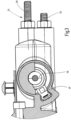
- in der Art einer Draufsicht, einen Ausschnitt aus
Fig. 2 mit einem Hall-Sensor für die Motorwelle; - Fig. 4
- einen Längsschnitt durch den Elektromotor nebst Lagerstellen zur drehbaren Führung der Motorwelle;
- Fig. 5
- einen Ausschnitt aus einem zweistufigen Planetenradgetriebe mit Getriebewelle nebst zugehörigen Sensorteilen, das sich unterhalb des Elektromotors nach der
Fig. 4 anschließt; - Fig. 6
- eine Ansicht auf das zweistufige Planetenradgetriebe nach der
Fig. 4 ; und - Fig. 7
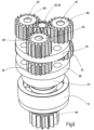
- eine perspektivische Ansicht auf das Planetenradgetriebe nach
Fig. 5 mit Hohlrad. - Unter Bezugnahme auf die Zeichnung wird die erfindungsgemäße Ventilvorrichtung am Beispiel eines Wegeventiles in Form eines sogenannten Schieberventils näher erläutert. Sofern Begriffe wie "Oberseite", "Oben" und "Unterseite" sowie "Unten" verwendet werden, beziehen sich diese Angaben auf eine normale Einbaulage, wie sie in den Figuren dargestellt ist.
- Gemäß der Darstellung nach der
Fig. 1 ist ein Ventilkolben 2 respektive Schieberkolben in einem Ventilgehäuse 4 entlang einer Achse 6 längsverfahrbar geführt. Das Ventilgehäuse 4 weist paarweise einander gegenüberliegende Längsseiten 8 und Stirnseiten 10, 12 auf. Ferner verfügt das Ventilgehäuse 4 über eine Oberseite 14 und eine Unterseite 16. Die Unterseite 16, gemäß der Darstellung nach derFig. 1 , ist der einfacheren Darstellung wegen nur abgebrochen dargestellt. Entlang der Oberseite 14 münden die Nutzanschlüsse A, B aus dem Ventilgehäuse 4 aus und entlang der Unterseite 16 die beiden Tankanschlüsse T, die zwischen sich den Druckversorgungsanschluss P aufnehmen. Alle genannten Anschlüsse A, B, P, T stellen die Fluidanschlussstellen des Ventilgehäuses 4 dar. - Eine im linken Gehäuseendbereich befindliche Federanordnung 18 mit einer Druckfeder als Energiespeicher, die an die linke Stirnseite 12 des Ventilgehäuses 4 anschließt, gibt in der bei derartigen Wegeventilen üblichen Weise für den Ventilkolben 2 eine Neutral- oder Mittelstellung vor, wie sie in der
Fig. 1 dargestellt ist. Des Weiteren weist das Ventilgehäuse 4 zwei sogenannte federbelastete Druckbegrenzungsventile 20 auf, die zur Absicherung bei zu hohen Drücken an dem jeweiligen Nutzanschluss A, B den - Fluidweg zum zugeordneten Tankanschluss T frei geben und insoweit einem ungewollten Druckanstieg entgegenwirken.
- Verfährt in Blickrichtung auf die
Fig. 1 gesehen der Ventilkolben 2 aus seiner insoweit gezeigten Neutralstellung nach rechts in eine Betätigungsstellung, wird der Druckversorgungsanschluss P für eine Fluidversorgung unter Druck mit dem Nutzanschluss A verbunden und im Rücklauf erfolgt ein Anschluss von Nutzanschluss B in Richtung des rechten Tankanschlusses T. Bei einer Auslenkung des Ventilkolbens nach links wird hingegen der Nutzanschluss B mit dem Pumpenanschluss oder Druckversorgungsanschluss P verbunden und der Nutzanschluss A mit dem linken Tankanschluss T. Dergestalt lässt sich beispielsweise ein hydraulischer Arbeitszylinder aus- und einfahren, der mit seiner Kolbenseite an den Nutzanschluss A fluidführend angeschlossen ist und mit seiner Stangenseite an den Nutzanschluss B. Dahingehende hydraulische Kreislaufführungen sind üblich, so dass an dieser Stelle hierauf nicht mehr näher eingegangen wird. - Des Weiteren verfügt die Ventilvorrichtung nach der
Fig. 1 noch über eine Notbetätigung 22, die mit dem Ventilkolben 2 zusammenwirkt und beispielsweise eine Rückstellung des Ventilkolbens 2 in seine, inFig. 1 gezeigte Ausgangs- oder Neutralstellung ermöglicht. Darüber hinaus ist noch eine Hublängenbegrenzung 24 mit zwei Stellschrauben 26, 28 für den Ventilkolben 2 vorgesehen. Auch die letztgenannte Ausgestaltung ist bei dahingehenden Ventilvorrichtungen üblich, so dass an dieser Stelle hierauf nicht mehr näher eingegangen wird. - In Blickrichtung auf die
Fig. 1 gesehen, schließt sich auf der rechten Stirnseite 10 des Ventilgehäuses 4 ein Antriebsgehäuse 30 an, das einen als Ganzes mit 32 bezeichneten Antriebsstrang aufnimmt. Der Antriebsstrang 32 beinhaltet unter anderem einen Elektromotor 34 als Antrieb, der vorzugsweise als bürstenloser Gleichstrommotor konzipiert ist. Die Einzelheiten des dahingehenden Elektromotors 34 sind insbesondere in derFig. 4 dargestellt. Auf der Unterseite respektive am unteren Ende des Elektromotors 34 schließt sich ein Getriebe 36 an, insbesondere in Form eines Untersetzungsgetriebes. Das dahingehende Getriebe 36 als zweistufiges Planetenradgetriebe ist insbesondere in derFig. 5 dargestellt. Vorzugsweise laufen alle bewegbaren Teile des Antriebsstranges 32 im Antriebsgehäuse 30 unter Öl. Des Weiteren ist eine, insbesondere in derFig. 2 gezeigte, Sensoreinrichtung 38 vorhanden, mit zwei Sensoren in Form eines oberen Hall-Sensors 40 und in Form eines unteren Hall-Sensors 42. Die dahingehende Sensoreinrichtung 38 mit ihren beiden Hall-Sensoren 40, 42 erlaubt die jeweilige Positionsüberwachung für Teile des Antriebsstranges 32 und erlaubt damit unmittelbar einen Rückschluss auf die jeweilige Position des Ventilkolbens 2 im Ventilgehäuse 4. Wie insbesondere dieFig. 4 zeigt, weist der Antriebsstrang 32 eine von dem Elektromotor 34 antreibbare Motorwelle 44 auf. Die Motorwelle 44 mündet auf ihren beiden freien Seiten aus dem Gehäuse des Elektromotors 34 aus und ist drehbar in ihrem endseitigen Bereich in üblichen Lagerstellen 48 geführt. Der im Motorgehäuse 46 aufgenommene Elektromotor 34 weist einen in Statorspulen 50 drehbar geführten Rotor 52 auf, der mittels Federvorspannung einer Druckfeder 54 in axialer Position im Motorgehäuse 46 drehbar gehalten ist und dergestalt sein Antriebsdrehmoment an die Motorwelle 44 weitergibt. Wie die Darstellung nach derFig. 2 zeigt, ist das kastenförmige Motorgehäuse 46 im Antriebsgehäuse 30 integriert. - Die Motorwelle 44 weist in Blickrichtung auf die
Fig. 4 gesehen an ihrem oberen Ende einen Permanentmagneten 56 auf und des Weiteren sieht man im oberen Bereich Anschlussstellen 58 in Form eines Steckerteils zwecks Stromversorgung der Statorspulen 50. An seinem dem gegenüberliegenden Ende ist die Motorwelle 44 mit einer Art Keilwellenverzahnung 60 versehen zwecks Eingriff in eine zugehörige Aufnahmestelle 62 einer oberen, ersten Planetenstufe 63 des zweistufigen Planetenradgetriebes 36. Wie insbesondere dieFig. 3 zeigt, wirkt der obere Permanentmagnet 56 mit dem im Antriebsgehäuse 30 stationär aufgenommenen oberen Hall-Sensor 40 zusammen. - In Blickrichtung auf die
Fig. 5 gesehen, mündet das Getriebe 36 an ihrem unteren Ende in eine Getriebewelle 64 aus, an deren unterem Ende ein Antriebsritzel 66 angeordnet ist, das gemäß der Darstellung nach denFig. 1 und2 mit einer Zahnstange 68 kämmt, auf deren linker Seite sich der Ventilkolben 2, vorzugsweise in einstückiger Bauweise mit der Zahnstange 68 anschließt. Die Getriebewelle 64 ist im Getriebegehäuse 70 mit dem Getriebe 36 mittels zweier Lagerstellen 72 drehbar, aber axial unverschiebbar geführt. An ihrem, dem Antriebsritzel 66 gegenüberliegenden Ende ist die Getriebewelle 64 wiederum mittels einer Keilwellenverbindung 74 an eine zweite, untere Planetenstufe 75 des Planetenradgetriebes 36 ausgangsseitig festgelegt. Die dahingehende Keilwellenverbindung 74 ragt gemäß der Darstellung nach derFig. 5 noch in einen mittleren Planetenträger 76 des Getriebes 36 hinein, jedoch ohne Ausübung einer Drehmomentübertragung in diesem Bereich. Zwischen den beiden Lagerstellen 72 ist ein weiterer Permanentmagnet 78 vorhanden, der drehfest mit der Getriebewelle 64 zusammenwirkt und den unteren Hall-Sensor 42 (s.Fig. 2 ) ansteuert. - Wie insbesondere die
Fig. 6 und7 zeigen, in Verbindung mit derFig. 5 , weist das zweistufige Planetenradgetriebe 36 die erste Planetenstufe 63 mit drei Planetenrädern 80 auf, die sich um ein Sonnenrad 82 drehen, das in der Art einer Keilwellenverzahnung 60 in die Aufnahmestelle 62 der ersten Planetenradstufe 63 eingreift. Die drei Planetenräder 80 mit gleicher Verzahnung sind über Achsen 84 drehbar auf dem ersten, oberen Planetenträger 76 geführt. Ferner kämmen die drei Planetenräder 80 außenumfangsseitig gemäß der Darstellung nach derFig. 7 in einem Hohlrad 86 ab, das gehäusefest mit der Getriebeummantelung 88 verbunden ist. Wie insbesondere die Darstellung nach derFig. 5 zeigt, durchgreifen die einzelnen Achsen 84 den oberen Planetenträger 76 und sind bis zu einem unteren Planetenträger 90 geführt. Insoweit sind koaxial zu den drei Planetenrädern 80 drei weitere Planetenräder 92 auf den Achsen 84 drehbar geführt und erstrecken sich zwischen dem oberen Planetenträger 76 und dem unteren Planetenträger 90. Die drei weiteren Planetenräder 92 weisen jeweils eine größere Zähnezahl auf als ein Planetenrad 80 der darüberliegenden ersten Planetenstufe 63. Die drei weiteren Planetenräder 92 bilden mit ihrem zweiten Planetenträger 90 und dem mittleren Sonnenrad 94, das insoweit gleichfalls eine Art Keilwellenverbindung 74 mit den Planetenrädern 92 eingeht, die zweite Planetenstufe 75 des Getriebes 36 aus. Auch insoweit kämmen dann die drei weiteren Planetenräder 92 außenumfangsseitig entlang eines von der Zähnezahl angepassten weiteren Hohlrades 96 ab. Gemäß der Darstellung nach derFig. 5 , ist sowohl das erste Hohlrad 86 als auch das zweite Hohlrad 96 Bestandteil der Getriebeummantelung 88, die gemäß der Darstellung nach derFig. 2 wiederum integraler Bestandteil des Antriebsgehäuses 30 ist. - Wird die Motorwelle 44 mittels des Elektromotors 34 angetrieben, treibt das zugehörige Sonnenrad 82 die drei umlaufenden Planetenräder 80 an und diese nehmen über ihre Achsen 84 die drei weiteren Planetenräder 92 in derselben Umlaufrichtung mit, wobei diese ihre dahingehende Drehbewegung an das mittlere Sonnenrad 94 der zweiten Planetenstufe 75 abtriebsseitig weitergeben, die mit der Getriebewelle 64 verbunden für den Zahnstangenantrieb des Ventilkolbens 2 das Antriebsritzel 66 drehend antreibt. Dabei laufen die jeweiligen Planetenräder 80, 92 an ihren zugeordneten Hohlrädern 86, 96 auf der Innenseite der Getriebeummantelung 88 ab. Dergestalt lassen sich sehr hohe Drehzahlen des Elektromotors in geringe Antriebsdrehzahlen für das Antriebsritzel 66 untersetzen.
- Für eine dahingehende Antriebsbewegung der Zahnstange 68 nebst Ventilkolben 2 wird dann mittels des oberen Hall-Sensors 40 sowohl die Drehbewegung für die Motorwelle 44 überwacht als auch über den unteren Hall-Sensor 42 die Drehbewegung der demgegenüber untersetzt drehenden Getriebewelle 64. Da das Getriebe 36 ein definiertes Untersetzungsverhältnis vorgibt, lässt sich dergestalt eine redundante Überwachung für die Bewegung des Ventilkolbens 2 herstellen.
- Des Weiteren besteht die Möglichkeit, gemäß der Darstellung nach der
Fig. 1 , in das Antriebsgehäuse 30 randseitig einen zusätzlichen Sensor in Form eines Drucksensors 98 aufzunehmen, der über einen Querkanal 100 den Fluiddruck im Bereich des rechten Druckbegrenzungsventils 20 überwacht. - Des Weiteren ist die Oberseite des Antriebsgehäuses von einem Deckelteil mit darin aufgenommener Platine 102 abgeschlossen. In vorteilhafter Weise ist die genannte Platine 102 waagerecht über dem Elektromotor 34 aufgenommen, so dass insoweit bauraumsparend die Positionsmessung über den oberen Hall-Sensor 40 erfolgen kann und zwar über den auf der Motorwelle 44 sitzenden Permanentmagneten 78. Weiterhin ist hierdurch eine einfache Anbindung der externen Steckerkontakte in Form der Anschlussstellen 58 realisiert, was im Rahmen einfach zu realisierender Einpresskontakte in die Platine 102 erfolgen kann. Des Weiteren verfügt die Platine 102 über eine nach außen freigelegte LED-Anzeige 104, über die sich der Betriebszustand für die gesamte Ventilvorrichtung ersehen lässt. Über eine auf der Unterseite der Platine 102 angebrachte Steckeranordnung 106, lässt sich darüber hinaus im Rahmen einer Art Längsverkettung (nicht dargestellt) verschiedene hintereinander angeordnete Ventilvorrichtungen gemäß der Darstellung nach der
Fig. 1 in Segmentbauweise zentral von einer Maschinensteuerung überwachen und ansteuern. - Des Weiteren sind die beiden Hall-Sensoren 40, 42 über eine gemeinsame, elektrische Versorgungsleitung 108 miteinander verbunden.
Claims (8)
- Ventilvorrichtung, bestehend aus mindestens einem, in einem Ventilgehäuse (4) längsverfahrbar angeordneten Ventilkolben (2), der mittels eines Antriebs (34) nebst zugehörigem Antriebsstrang (32) bewegt einzelne im Ventilgehäuse (4) vorhandene Fluidanschlussstellen (A, B, P, T) miteinander fluidführend verbindet oder voneinander trennt, wobei mittels einer Sensoreinrichtung (38) die jeweilige Position des Antriebsstranges (32) und damit die jeweilige Position des Ventilkolbens (2) im Ventilgehäuse (4) überwacht ist,wobei der Antrieb (34) ein Elektromotor (34) ist,wobei der Antriebsstrang (32) zumindest eine von dem Elektromotor (34) antreibbare Motorwelle (44) aufweist, undwobei die Sensoreinrichtung (38) einen Sensor (40) aufweist, der die Motorwelle (44) überwacht,dadurch gekennzeichnet,dass die Motorwelle (44) mit ihrem einen Ende in ein Getriebe (36) ausmündet, das mit einer Getriebewelle (64) ein Antriebsritzel (66) ansteuert, das mit einer Zahnstange (68) kämmt, die mit dem Ventilkolben (2) zusammenwirkt, unddass die Sensoreinrichtung (38) einen Sensor (42) aufweist, der die Getriebewelle (64) überwacht.
- Ventilvorrichtung nach Anspruch 1, dadurch gekennzeichnet, dass die Motorwelle (44) an ihrem anderen, dem Getriebe (36) abgekehrten Ende, über den Elektromotor (34) vorstehend, drehbar in einem Antriebsgehäuse (30) gelagert ist.
- Ventilvorrichtung nach Anspruch 1 oder 2, dadurch gekennzeichnet, dass der Sensor (40) der die Motorwelle (44) überwacht stationär im Antriebsgehäuse (30) aufgenommen ist und den Teil der Motorwelle (44) überwacht, die mit ihrem anderen Ende über den Elektromotor (34) nach oben hin vorsteht.
- Ventilvorrichtung nach einem der vorstehenden Ansprüche, dadurch gekennzeichnet, dass der Sensor (42), der die Getriebewelle (64) überwacht stationär im Antriebsgehäuse (30) aufgenommen ist und den Teil der Getriebewelle (64) überwacht, der in Richtung des Antriebsritzels (66) für die Zahnstange (68) nach unten hin über den Elektromotor (34) vorsteht.
- Ventilvorrichtung nach einem der vorstehenden Ansprüche, dadurch gekennzeichnet, dass der jeweilige Sensor ein Hall-Sensor (40, 42) ist, der mit der Motor- (44) und/oder der Getriebewelle (64) zusammenwirkt, die für einen Messwertabgriff einen Permanentmagneten (56; 78) aufweist.
- Ventilvorrichtung nach einem der vorstehenden Ansprüche, dadurch gekennzeichnet, dass für die Untersetzung der Motordrehzahl zwecks Antrieb des Antriebsritzels (66) für den Zahnstangentrieb (68) des Ventilkolbens (2) zwischen Motor (44) - und Getriebewelle (64) als Getriebe (36) ein Planetenradgetriebe, vorzugsweise ein zweistufiges Planetenradgetriebe, eingesetzt ist.
- Ventilvorrichtung nach einem der vorstehenden Ansprüche, dadurch gekennzeichnet, dass der Elektromotor (34) ein bürstenloser Gleichstrommotor ist.
- Ventilvorrichtung nach einem der vorstehenden Ansprüche, dadurch gekennzeichnet, dass das Ventilgehäuse (4) und das Antriebsgehäuse (30) eigenständige miteinander koppelbare Gehäuseeinheiten darstellen.
Applications Claiming Priority (2)
| Application Number | Priority Date | Filing Date | Title |
|---|---|---|---|
| DE102021000749.2A DE102021000749A1 (de) | 2021-02-13 | 2021-02-13 | Ventilvorrichtung |
| PCT/EP2022/052236 WO2022171478A1 (de) | 2021-02-13 | 2022-01-31 | Ventilvorrichtung |
Publications (3)
| Publication Number | Publication Date |
|---|---|
| EP4267872A1 EP4267872A1 (de) | 2023-11-01 |
| EP4267872C0 EP4267872C0 (de) | 2024-08-28 |
| EP4267872B1 true EP4267872B1 (de) | 2024-08-28 |
Family
ID=80222609
Family Applications (1)
| Application Number | Title | Priority Date | Filing Date |
|---|---|---|---|
| EP22702952.7A Active EP4267872B1 (de) | 2021-02-13 | 2022-01-31 | Ventilvorrichtung |
Country Status (5)
| Country | Link |
|---|---|
| US (1) | US12467482B2 (de) |
| EP (1) | EP4267872B1 (de) |
| CN (1) | CN117063002A (de) |
| DE (1) | DE102021000749A1 (de) |
| WO (1) | WO2022171478A1 (de) |
Cited By (1)
| Publication number | Priority date | Publication date | Assignee | Title |
|---|---|---|---|---|
| US12467482B2 (en) | 2021-02-13 | 2025-11-11 | Hydac Mobilhydraulik Gmbh | Valve device |
Family Cites Families (10)
| Publication number | Priority date | Publication date | Assignee | Title |
|---|---|---|---|---|
| DE3825035B4 (de) | 1988-07-09 | 2006-11-23 | Flux-Geräte GmbH | Bürstenloser, elektrisch kommutierter Motor für eine Faß- oder eine Behälterpumpe zum Betieb an einem Wechselspannungsnetz |
| DE3832304A1 (de) | 1988-09-20 | 1990-03-29 | Haberecht Helga | Stellantrieb |
| US5806565A (en) * | 1994-02-04 | 1998-09-15 | Microhydraulics Inc. | Hydraulic valves |
| DE102014204066A1 (de) | 2014-03-06 | 2015-09-10 | Robert Bosch Gmbh | Ventilscheibe |
| DE102015015685A1 (de) | 2015-12-03 | 2017-06-08 | Hydac System Gmbh | Ventilvorrichtung |
| EP3208119A1 (de) * | 2016-02-18 | 2017-08-23 | Haldex Brake Products Aktiebolag | Mechanisch betätigte niveauregelventileinrichtung |
| US11199272B2 (en) * | 2018-05-18 | 2021-12-14 | Hydac Systems & Services Gmbh | Control device |
| DE102018207927A1 (de) | 2018-05-18 | 2019-11-21 | Hydac Systems & Services Gmbh | Steuervorrichtung |
| CN110529646B (zh) * | 2019-09-20 | 2024-04-26 | 四川芯智热控技术有限公司 | 一种比例调节电控执行器 |
| DE102021000749A1 (de) | 2021-02-13 | 2022-08-18 | Hydac Mobilhydraulik Gmbh | Ventilvorrichtung |
-
2021
- 2021-02-13 DE DE102021000749.2A patent/DE102021000749A1/de not_active Withdrawn
-
2022
- 2022-01-31 EP EP22702952.7A patent/EP4267872B1/de active Active
- 2022-01-31 WO PCT/EP2022/052236 patent/WO2022171478A1/de not_active Ceased
- 2022-01-31 CN CN202280014529.1A patent/CN117063002A/zh active Pending
- 2022-01-31 US US18/546,412 patent/US12467482B2/en active Active
Cited By (1)
| Publication number | Priority date | Publication date | Assignee | Title |
|---|---|---|---|---|
| US12467482B2 (en) | 2021-02-13 | 2025-11-11 | Hydac Mobilhydraulik Gmbh | Valve device |
Also Published As
| Publication number | Publication date |
|---|---|
| US12467482B2 (en) | 2025-11-11 |
| WO2022171478A1 (de) | 2022-08-18 |
| CN117063002A (zh) | 2023-11-14 |
| EP4267872C0 (de) | 2024-08-28 |
| US20240125338A1 (en) | 2024-04-18 |
| EP4267872A1 (de) | 2023-11-01 |
| DE102021000749A1 (de) | 2022-08-18 |
Similar Documents
| Publication | Publication Date | Title |
|---|---|---|
| DE2044441C3 (de) | Aus einem hydrostatisch-mechanischen Überlagerungsgetriebe mit Leistungsverzweigung und einem Generator bestehende Antriebseinheit | |
| EP3384191B1 (de) | Ventilvorrichtung | |
| EP1404956B1 (de) | Elektromotorischer antrieb mit einer schnecke | |
| DE102019112021A1 (de) | Hub-Dreh-Modul | |
| DE102021203043A1 (de) | Schaltbares Radnabengetriebe und Antriebssystem mit einem solchen schaltbaren Radnabengetriebe | |
| EP1485636B1 (de) | Stellantrieb | |
| EP0428895A2 (de) | Stellantrieb | |
| EP3807112A1 (de) | Antriebseinheit für einen antriebsstrang eines elektrisch antreibbaren kraftfahrzeugs und antriebsanordnung | |
| DE102015112685B3 (de) | Antrieb zum Bewegen eines Flügels | |
| DE102014206230A1 (de) | Schwingungsdämpfer | |
| DE102004052562B3 (de) | Kraftfahrzeuglenkung mit Überlagerungsgetriebe | |
| EP1044128A1 (de) | Ventilanordnung für servolenkungen | |
| DE102021000749A1 (de) | Ventilvorrichtung | |
| EP3453104B1 (de) | Rotierende elektrische maschine | |
| EP1910707B1 (de) | Stellantrieb für armaturen mit einem planetengetriebe | |
| DE10354594B4 (de) | Antriebseinheit eines Schaltgerätes einer gasisolierten Schaltanlage und Baukastensystem zur Bildung einer Antriebseinheit | |
| DE10234738B4 (de) | Aktuator | |
| DE102007005713A1 (de) | Lenkgetriebe | |
| EP1671052B1 (de) | Stellvorrichtung | |
| DE102007058809A1 (de) | Modular kombinierbare Teile, zum Bau einer Vielzahl von Antrieben mit unterschiedlichen Eigenschaften | |
| WO2020228881A1 (de) | Antriebsvorrichtung mit einem unterhalb einer leistungselektronikeinheit angeordneten wärmetauscher | |
| DE102024107399B3 (de) | Antrieb für eine Tür oder ein Fenster mit verbessertem Wirkungsgrad | |
| DE10258848A1 (de) | Vorrichtung zum Betätigen von Verstellkomponenten im Kraftfahrzeug | |
| DE102019005151A1 (de) | Antriebseinrichtung für einen Kraftwagen, insbesondere für einen Personenkraftwagen | |
| EP1959176A1 (de) | Antrieb für Kugelhähne |
Legal Events
| Date | Code | Title | Description |
|---|---|---|---|
| STAA | Information on the status of an ep patent application or granted ep patent |
Free format text: STATUS: UNKNOWN |
|
| STAA | Information on the status of an ep patent application or granted ep patent |
Free format text: STATUS: THE INTERNATIONAL PUBLICATION HAS BEEN MADE |
|
| PUAI | Public reference made under article 153(3) epc to a published international application that has entered the european phase |
Free format text: ORIGINAL CODE: 0009012 |
|
| STAA | Information on the status of an ep patent application or granted ep patent |
Free format text: STATUS: REQUEST FOR EXAMINATION WAS MADE |
|
| 17P | Request for examination filed |
Effective date: 20230727 |
|
| AK | Designated contracting states |
Kind code of ref document: A1 Designated state(s): AL AT BE BG CH CY CZ DE DK EE ES FI FR GB GR HR HU IE IS IT LI LT LU LV MC MK MT NL NO PL PT RO RS SE SI SK SM TR |
|
| GRAP | Despatch of communication of intention to grant a patent |
Free format text: ORIGINAL CODE: EPIDOSNIGR1 |
|
| STAA | Information on the status of an ep patent application or granted ep patent |
Free format text: STATUS: GRANT OF PATENT IS INTENDED |
|
| DAV | Request for validation of the european patent (deleted) | ||
| DAX | Request for extension of the european patent (deleted) | ||
| INTG | Intention to grant announced |
Effective date: 20240517 |
|
| RAP3 | Party data changed (applicant data changed or rights of an application transferred) |
Owner name: HYDAC MOBILHYDRAULIK GMBH |
|
| GRAS | Grant fee paid |
Free format text: ORIGINAL CODE: EPIDOSNIGR3 |
|
| GRAA | (expected) grant |
Free format text: ORIGINAL CODE: 0009210 |
|
| STAA | Information on the status of an ep patent application or granted ep patent |
Free format text: STATUS: THE PATENT HAS BEEN GRANTED |
|
| AK | Designated contracting states |
Kind code of ref document: B1 Designated state(s): AL AT BE BG CH CY CZ DE DK EE ES FI FR GB GR HR HU IE IS IT LI LT LU LV MC MK MT NL NO PL PT RO RS SE SI SK SM TR |
|
| REG | Reference to a national code |
Ref country code: CH Ref legal event code: EP |
|
| REG | Reference to a national code |
Ref country code: DE Ref legal event code: R096 Ref document number: 502022001576 Country of ref document: DE |
|
| REG | Reference to a national code |
Ref country code: IE Ref legal event code: FG4D Free format text: LANGUAGE OF EP DOCUMENT: GERMAN |
|
| U01 | Request for unitary effect filed |
Effective date: 20240828 |
|
| U07 | Unitary effect registered |
Designated state(s): AT BE BG DE DK EE FI FR IT LT LU LV MT NL PT RO SE SI Effective date: 20240905 |
|
| PG25 | Lapsed in a contracting state [announced via postgrant information from national office to epo] |
Ref country code: NO Free format text: LAPSE BECAUSE OF FAILURE TO SUBMIT A TRANSLATION OF THE DESCRIPTION OR TO PAY THE FEE WITHIN THE PRESCRIBED TIME-LIMIT Effective date: 20241128 |
|
| PG25 | Lapsed in a contracting state [announced via postgrant information from national office to epo] |
Ref country code: PL Free format text: LAPSE BECAUSE OF FAILURE TO SUBMIT A TRANSLATION OF THE DESCRIPTION OR TO PAY THE FEE WITHIN THE PRESCRIBED TIME-LIMIT Effective date: 20240828 Ref country code: GR Free format text: LAPSE BECAUSE OF FAILURE TO SUBMIT A TRANSLATION OF THE DESCRIPTION OR TO PAY THE FEE WITHIN THE PRESCRIBED TIME-LIMIT Effective date: 20241129 |
|
| PG25 | Lapsed in a contracting state [announced via postgrant information from national office to epo] |
Ref country code: IS Free format text: LAPSE BECAUSE OF FAILURE TO SUBMIT A TRANSLATION OF THE DESCRIPTION OR TO PAY THE FEE WITHIN THE PRESCRIBED TIME-LIMIT Effective date: 20241228 |
|
| PG25 | Lapsed in a contracting state [announced via postgrant information from national office to epo] |
Ref country code: HR Free format text: LAPSE BECAUSE OF FAILURE TO SUBMIT A TRANSLATION OF THE DESCRIPTION OR TO PAY THE FEE WITHIN THE PRESCRIBED TIME-LIMIT Effective date: 20240828 |
|
| PG25 | Lapsed in a contracting state [announced via postgrant information from national office to epo] |
Ref country code: RS Free format text: LAPSE BECAUSE OF FAILURE TO SUBMIT A TRANSLATION OF THE DESCRIPTION OR TO PAY THE FEE WITHIN THE PRESCRIBED TIME-LIMIT Effective date: 20241128 Ref country code: ES Free format text: LAPSE BECAUSE OF FAILURE TO SUBMIT A TRANSLATION OF THE DESCRIPTION OR TO PAY THE FEE WITHIN THE PRESCRIBED TIME-LIMIT Effective date: 20240828 |
|
| PG25 | Lapsed in a contracting state [announced via postgrant information from national office to epo] |
Ref country code: RS Free format text: LAPSE BECAUSE OF FAILURE TO SUBMIT A TRANSLATION OF THE DESCRIPTION OR TO PAY THE FEE WITHIN THE PRESCRIBED TIME-LIMIT Effective date: 20241128 Ref country code: PL Free format text: LAPSE BECAUSE OF FAILURE TO SUBMIT A TRANSLATION OF THE DESCRIPTION OR TO PAY THE FEE WITHIN THE PRESCRIBED TIME-LIMIT Effective date: 20240828 Ref country code: NO Free format text: LAPSE BECAUSE OF FAILURE TO SUBMIT A TRANSLATION OF THE DESCRIPTION OR TO PAY THE FEE WITHIN THE PRESCRIBED TIME-LIMIT Effective date: 20241128 Ref country code: IS Free format text: LAPSE BECAUSE OF FAILURE TO SUBMIT A TRANSLATION OF THE DESCRIPTION OR TO PAY THE FEE WITHIN THE PRESCRIBED TIME-LIMIT Effective date: 20241228 Ref country code: HR Free format text: LAPSE BECAUSE OF FAILURE TO SUBMIT A TRANSLATION OF THE DESCRIPTION OR TO PAY THE FEE WITHIN THE PRESCRIBED TIME-LIMIT Effective date: 20240828 Ref country code: GR Free format text: LAPSE BECAUSE OF FAILURE TO SUBMIT A TRANSLATION OF THE DESCRIPTION OR TO PAY THE FEE WITHIN THE PRESCRIBED TIME-LIMIT Effective date: 20241129 Ref country code: ES Free format text: LAPSE BECAUSE OF FAILURE TO SUBMIT A TRANSLATION OF THE DESCRIPTION OR TO PAY THE FEE WITHIN THE PRESCRIBED TIME-LIMIT Effective date: 20240828 |
|
| U20 | Renewal fee for the european patent with unitary effect paid |
Year of fee payment: 4 Effective date: 20250131 |
|
| PG25 | Lapsed in a contracting state [announced via postgrant information from national office to epo] |
Ref country code: SM Free format text: LAPSE BECAUSE OF FAILURE TO SUBMIT A TRANSLATION OF THE DESCRIPTION OR TO PAY THE FEE WITHIN THE PRESCRIBED TIME-LIMIT Effective date: 20240828 |
|
| PG25 | Lapsed in a contracting state [announced via postgrant information from national office to epo] |
Ref country code: CZ Free format text: LAPSE BECAUSE OF FAILURE TO SUBMIT A TRANSLATION OF THE DESCRIPTION OR TO PAY THE FEE WITHIN THE PRESCRIBED TIME-LIMIT Effective date: 20240828 |
|
| PG25 | Lapsed in a contracting state [announced via postgrant information from national office to epo] |
Ref country code: SK Free format text: LAPSE BECAUSE OF FAILURE TO SUBMIT A TRANSLATION OF THE DESCRIPTION OR TO PAY THE FEE WITHIN THE PRESCRIBED TIME-LIMIT Effective date: 20240828 |
|
| PLBE | No opposition filed within time limit |
Free format text: ORIGINAL CODE: 0009261 |
|
| STAA | Information on the status of an ep patent application or granted ep patent |
Free format text: STATUS: NO OPPOSITION FILED WITHIN TIME LIMIT |
|
| 26N | No opposition filed |
Effective date: 20250530 |
|
| PG25 | Lapsed in a contracting state [announced via postgrant information from national office to epo] |
Ref country code: MC Free format text: LAPSE BECAUSE OF FAILURE TO SUBMIT A TRANSLATION OF THE DESCRIPTION OR TO PAY THE FEE WITHIN THE PRESCRIBED TIME-LIMIT Effective date: 20240828 |
|
| PGFP | Annual fee paid to national office [announced via postgrant information from national office to epo] |
Ref country code: GB Payment date: 20251208 Year of fee payment: 5 |
|
| PG25 | Lapsed in a contracting state [announced via postgrant information from national office to epo] |
Ref country code: IE Free format text: LAPSE BECAUSE OF NON-PAYMENT OF DUE FEES Effective date: 20250131 |
|
| REG | Reference to a national code |
Ref country code: CH Ref legal event code: U11 Free format text: ST27 STATUS EVENT CODE: U-0-0-U10-U11 (AS PROVIDED BY THE NATIONAL OFFICE) Effective date: 20260201 |
|
| U20 | Renewal fee for the european patent with unitary effect paid |
Year of fee payment: 5 Effective date: 20260202 |
|
| PGFP | Annual fee paid to national office [announced via postgrant information from national office to epo] |
Ref country code: CH Payment date: 20260201 Year of fee payment: 5 |