EP4267696B1 - Verfahren zur depolymerisation von kunststoffabfallmaterial - Google Patents
Verfahren zur depolymerisation von kunststoffabfallmaterial Download PDFInfo
- Publication number
- EP4267696B1 EP4267696B1 EP21843929.7A EP21843929A EP4267696B1 EP 4267696 B1 EP4267696 B1 EP 4267696B1 EP 21843929 A EP21843929 A EP 21843929A EP 4267696 B1 EP4267696 B1 EP 4267696B1
- Authority
- EP
- European Patent Office
- Prior art keywords
- reactor
- char
- depolymerization
- process according
- chamber
- Prior art date
- Legal status (The legal status is an assumption and is not a legal conclusion. Google has not performed a legal analysis and makes no representation as to the accuracy of the status listed.)
- Active
Links
Images


Classifications
-
- C—CHEMISTRY; METALLURGY
- C10—PETROLEUM, GAS OR COKE INDUSTRIES; TECHNICAL GASES CONTAINING CARBON MONOXIDE; FUELS; LUBRICANTS; PEAT
- C10B—DESTRUCTIVE DISTILLATION OF CARBONACEOUS MATERIALS FOR PRODUCTION OF GAS, COKE, TAR, OR SIMILAR MATERIALS
- C10B57/00—Other carbonising or coking processes; Features of destructive distillation processes in general
- C10B57/005—After-treatment of coke, e.g. calcination desulfurization
-
- C—CHEMISTRY; METALLURGY
- C07—ORGANIC CHEMISTRY
- C07C—ACYCLIC OR CARBOCYCLIC COMPOUNDS
- C07C4/00—Preparation of hydrocarbons from hydrocarbons containing a larger number of carbon atoms
- C07C4/22—Preparation of hydrocarbons from hydrocarbons containing a larger number of carbon atoms by depolymerisation to the original monomer, e.g. dicyclopentadiene to cyclopentadiene
-
- C—CHEMISTRY; METALLURGY
- C10—PETROLEUM, GAS OR COKE INDUSTRIES; TECHNICAL GASES CONTAINING CARBON MONOXIDE; FUELS; LUBRICANTS; PEAT
- C10B—DESTRUCTIVE DISTILLATION OF CARBONACEOUS MATERIALS FOR PRODUCTION OF GAS, COKE, TAR, OR SIMILAR MATERIALS
- C10B53/00—Destructive distillation, specially adapted for particular solid raw materials or solid raw materials in special form
- C10B53/07—Destructive distillation, specially adapted for particular solid raw materials or solid raw materials in special form of solid raw materials consisting of synthetic polymeric materials, e.g. tyres
-
- C—CHEMISTRY; METALLURGY
- C10—PETROLEUM, GAS OR COKE INDUSTRIES; TECHNICAL GASES CONTAINING CARBON MONOXIDE; FUELS; LUBRICANTS; PEAT
- C10G—CRACKING HYDROCARBON OILS; PRODUCTION OF LIQUID HYDROCARBON MIXTURES, e.g. BY DESTRUCTIVE HYDROGENATION, OLIGOMERISATION, POLYMERISATION; RECOVERY OF HYDROCARBON OILS FROM OIL-SHALE, OIL-SAND, OR GASES; REFINING MIXTURES MAINLY CONSISTING OF HYDROCARBONS; REFORMING OF NAPHTHA; MINERAL WAXES
- C10G1/00—Production of liquid hydrocarbon mixtures from oil-shale, oil-sand, or non-melting solid carbonaceous or similar materials, e.g. wood, coal
- C10G1/002—Production of liquid hydrocarbon mixtures from oil-shale, oil-sand, or non-melting solid carbonaceous or similar materials, e.g. wood, coal in combination with oil conversion- or refining processes
-
- C—CHEMISTRY; METALLURGY
- C10—PETROLEUM, GAS OR COKE INDUSTRIES; TECHNICAL GASES CONTAINING CARBON MONOXIDE; FUELS; LUBRICANTS; PEAT
- C10G—CRACKING HYDROCARBON OILS; PRODUCTION OF LIQUID HYDROCARBON MIXTURES, e.g. BY DESTRUCTIVE HYDROGENATION, OLIGOMERISATION, POLYMERISATION; RECOVERY OF HYDROCARBON OILS FROM OIL-SHALE, OIL-SAND, OR GASES; REFINING MIXTURES MAINLY CONSISTING OF HYDROCARBONS; REFORMING OF NAPHTHA; MINERAL WAXES
- C10G1/00—Production of liquid hydrocarbon mixtures from oil-shale, oil-sand, or non-melting solid carbonaceous or similar materials, e.g. wood, coal
- C10G1/10—Production of liquid hydrocarbon mixtures from oil-shale, oil-sand, or non-melting solid carbonaceous or similar materials, e.g. wood, coal from rubber or rubber waste
-
- C—CHEMISTRY; METALLURGY
- C10—PETROLEUM, GAS OR COKE INDUSTRIES; TECHNICAL GASES CONTAINING CARBON MONOXIDE; FUELS; LUBRICANTS; PEAT
- C10L—FUELS NOT OTHERWISE PROVIDED FOR; NATURAL GAS; SYNTHETIC NATURAL GAS OBTAINED BY PROCESSES NOT COVERED BY SUBCLASSES C10G OR C10K; LIQUIFIED PETROLEUM GAS; USE OF ADDITIVES TO FUELS OR FIRES; FIRE-LIGHTERS
- C10L1/00—Liquid carbonaceous fuels
- C10L1/04—Liquid carbonaceous fuels essentially based on blends of hydrocarbons
-
- C—CHEMISTRY; METALLURGY
- C10—PETROLEUM, GAS OR COKE INDUSTRIES; TECHNICAL GASES CONTAINING CARBON MONOXIDE; FUELS; LUBRICANTS; PEAT
- C10G—CRACKING HYDROCARBON OILS; PRODUCTION OF LIQUID HYDROCARBON MIXTURES, e.g. BY DESTRUCTIVE HYDROGENATION, OLIGOMERISATION, POLYMERISATION; RECOVERY OF HYDROCARBON OILS FROM OIL-SHALE, OIL-SAND, OR GASES; REFINING MIXTURES MAINLY CONSISTING OF HYDROCARBONS; REFORMING OF NAPHTHA; MINERAL WAXES
- C10G2300/00—Aspects relating to hydrocarbon processing covered by groups C10G1/00 - C10G99/00
- C10G2300/10—Feedstock materials
- C10G2300/1003—Waste materials
-
- C—CHEMISTRY; METALLURGY
- C10—PETROLEUM, GAS OR COKE INDUSTRIES; TECHNICAL GASES CONTAINING CARBON MONOXIDE; FUELS; LUBRICANTS; PEAT
- C10J—PRODUCTION OF PRODUCER GAS, WATER-GAS, SYNTHESIS GAS FROM SOLID CARBONACEOUS MATERIAL, OR MIXTURES CONTAINING THESE GASES; CARBURETTING AIR OR OTHER GASES
- C10J2300/00—Details of gasification processes
- C10J2300/09—Details of the feed, e.g. feeding of spent catalyst, inert gas or halogens
- C10J2300/0913—Carbonaceous raw material
- C10J2300/094—Char
-
- C—CHEMISTRY; METALLURGY
- C10—PETROLEUM, GAS OR COKE INDUSTRIES; TECHNICAL GASES CONTAINING CARBON MONOXIDE; FUELS; LUBRICANTS; PEAT
- C10L—FUELS NOT OTHERWISE PROVIDED FOR; NATURAL GAS; SYNTHETIC NATURAL GAS OBTAINED BY PROCESSES NOT COVERED BY SUBCLASSES C10G OR C10K; LIQUIFIED PETROLEUM GAS; USE OF ADDITIVES TO FUELS OR FIRES; FIRE-LIGHTERS
- C10L2290/00—Fuel preparation or upgrading, processes or apparatus therefore, comprising specific process steps or apparatus units
- C10L2290/02—Combustion or pyrolysis
-
- C—CHEMISTRY; METALLURGY
- C10—PETROLEUM, GAS OR COKE INDUSTRIES; TECHNICAL GASES CONTAINING CARBON MONOXIDE; FUELS; LUBRICANTS; PEAT
- C10L—FUELS NOT OTHERWISE PROVIDED FOR; NATURAL GAS; SYNTHETIC NATURAL GAS OBTAINED BY PROCESSES NOT COVERED BY SUBCLASSES C10G OR C10K; LIQUIFIED PETROLEUM GAS; USE OF ADDITIVES TO FUELS OR FIRES; FIRE-LIGHTERS
- C10L5/00—Solid fuels
- C10L5/40—Solid fuels essentially based on materials of non-mineral origin
- C10L5/44—Solid fuels essentially based on materials of non-mineral origin on vegetable substances
- C10L5/447—Carbonized vegetable substances, e.g. charcoal, or produced by hydrothermal carbonization of biomass
-
- Y—GENERAL TAGGING OF NEW TECHNOLOGICAL DEVELOPMENTS; GENERAL TAGGING OF CROSS-SECTIONAL TECHNOLOGIES SPANNING OVER SEVERAL SECTIONS OF THE IPC; TECHNICAL SUBJECTS COVERED BY FORMER USPC CROSS-REFERENCE ART COLLECTIONS [XRACs] AND DIGESTS
- Y02—TECHNOLOGIES OR APPLICATIONS FOR MITIGATION OR ADAPTATION AGAINST CLIMATE CHANGE
- Y02W—CLIMATE CHANGE MITIGATION TECHNOLOGIES RELATED TO WASTEWATER TREATMENT OR WASTE MANAGEMENT
- Y02W30/00—Technologies for solid waste management
- Y02W30/50—Reuse, recycling or recovery technologies
- Y02W30/62—Plastics recycling; Rubber recycling
Definitions
- the present disclosure relates to the field of depolymerization of plastic waste material into new products, comprising hydrocarbon oil, which have valuable and useful properties.
- the present disclosure relates to a process for converting plastics to liquid hydrocarbons, in particular to be used as hydrocarbon feedstock.
- plastic waste is either used as a source of thermal energy in plants such as incinerators, or simply stored in landfills which, as mentioned, contribute to degrade the earth environment by raising the CO 2 emissions and by the release of hazardous chemicals.
- Thermocatalysis is a basic process whereby plastic waste material is converted to liquid fuel (pyrolytic product) by effect of thermal and optionally catalytical degradation in the absence of oxygen.
- Plastic waste is typically first melted within a stainless steel chamber under an inert purging gas, such as nitrogen. In a first thermal step this chamber heats the molten material to a gaseous state which, in a successive thermocatalytic step, is cracked to form hydrocarbon chains of variable length.
- Hot pyrolytic gases are then condensed in one or more condensers to yield a hydrocarbon distillate comprising straight and branched chain aliphatic, cyclic aliphatic and aromatic hydrocarbons (pyrolytic oil).
- pyrolytic oil straight and branched chain aliphatic, cyclic aliphatic and aromatic hydrocarbons
- the resulting mixture is used in a variety of applications but, in any case, the requirement of product consistency and quality has always to be met. Also in view of the unstable composition of the plastic waste raw material, quality consistency of the recovered oil is difficult to be met.
- the use of one or more catalytic cracking stages helps in lowering the operative degrading temperature and may also drive the product composition towards the desired target.
- the amount of catalyst to be used ranges from 10 to 200% by weight relative to the amount of plastic to be treated. This greatly impacts on the costs per unit of recovered oil and, in order to be cost sustainable, it makes virtually mandatory for the plant to be endowed with a separate section for catalyst recovery.
- the process according to the present disclosure is very flexible and can be fed with a wide range of plastic waste composition as, for example, a heterogeneous mixture of waste plastic materials (called Plasmix in Italy) in which polyolefins are the most abundant component but for which a further sorting step is no longer economical. It is preferred, especially when the pyrolytic product is to be recirculated back to a cracking/refining unit, to depolymerize a plastic waste mixture in which the polyolefin (PE and PP) content is equal to or higher than 70%wt.
- PE and PP polyolefin
- the heating temperature in the pretreatment stage is appropriately set to a temperature in accordance with the kind and content of the plastic contained in the waste plastic material such that pyrolytic decomposition of the plastic material to be treated is inhibited.
- a temperature is, in general, within a range of 100°C to 300°C, and preferably, 150°C to 250°C. At a temperature close to 300°C or more, elimination of HCl from the PVC resin possibly present, takes place.
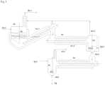
- the depolymerization reactor (2) preferably has a cylindrical section, preferably with a rounded bottom.
- the composition within the reactor covers a broad range of hydrocarbons from methane to heavier products, both saturated and olefinic, with linear or highly branched structures. Some aromatic product can be also present as well as fused rings structures.
- the content of the reactor (2) can be defined as coexistence of a liquid slurry phase, in which solid especially carbonaceous substances, and inorganic substances, are dispersed in a liquid hydrocarbon mixture, and a gaseous phase.
- part of the liquid slurry withdrawn from the the reactor (2) is recirculated, via a recycling pump (7), back to the reactor top optionally through an external heater (8).
- heat to the external heater is preferably provided by the molten salt. This embodiment may provide both increased homogeneity of reactor content and reactor heating.
- the liquid slurry portion recirculated to the reactor is withdrawn from a point of the reactor different from the point of the withdrawal of the liquid slurry portion sent to the char handling,
- both the liquid slurry portion recirculated to the reactor and the liquid slurry portion sent to the char handling are withdrawn from the same point and then successively split.
- the split between the portion of liquid slurry directed to char handling and the portion recirculated to the reactor can take place either before or after the recycling pump (7).
- the liquid slurry is first fed to a dedicated vessel equipped with a lower and upper exit point.
- the liquid portion directed to char handling (6) is withdrawn in a concentrated form the lower exit point while the liquid portion to be recycled to the reactor (2) is withdrawn from the upper exit point.
- the gaseous effluent comprises a mixture of light hydrocarbons which may also include some heavy hydrocarbons and char particles entrained.
- the gaseous effluent are conveyed from the reactor top to a condenser (3) preferably operated at a pressure slightly lower than that of the reactor .
- the condenser (3) is better designed as a scrubber column in order to suppress the entrained char.
- the condenser temperature is selected in such a way that the heavy hydrocarbons are condensed and the light hydrocarbons are released as gaseous stream.
- the gaseous stream (H 2 and light hydrocarbons) is conveyed to the further condensation unit (5) working at a temperature lower than the condensation unit (3) from which oil is recovered.
- the operative temperature of the condensing unit (3) may vary in a wide range also depending on the operative pressure.
- the temperature referred to atmospheric pressure, can be from 20°C to 200°C more preferably from 50 to 200°C and especially from 60 to 180°C.
- the temperature range can be of course different when a higher operating pressure is chosen.
- the condenser unit (3) was operated at about 80°C and the condensed liquid was sampled and analyzed with GC analysis.
- a dephlegmator (partial condenser) is installed on top of the scrubber and works at a temperature lower than that inside the column.
- the condensate flows down as reflux for the scrubber by virtue of gravity.
- the dephlegmator can either be installed as a separate piece of equipment or inside the scrubber.
- the second depolymerization reactor (4) is preferably of the same type as the first one and more preferably a continuously stirred tank reactor.
- reactor (4) Since the reactor (4) is fed with the condensed effluents coming from the reactor (2) it contains less impurities and produces less char. Preferably, fresh catalyst is fed to reactor (4) through conduit (15).
- the catalyst can be selected from those active as depolymerization/cracking catalysts in thermocatalytic processes.
- it can be selected from metal oxides, heteropolyacids, mesoporous silica, aluminosilicates catalysts, such as halloysite and kaolinite, and preferably from zeolites.
- particularly preferred zeolites are synthetic Y-type zeolite and ZSM-5.
- the amount of catalyst feed is not more than 10% preferably not more than 5% and especially not more than 2% wt with respect to the plastic waste feed.
- the catalyst is injected into the second reactor as powder dispersed into a hydrocarbon oil preferably the liquid pyrolytic product (oil) obtained from condensation units (3) or (5), preferably from condensation unit (3).
- the catalyst slurry is prepared in a pot, continuously stirred vessel where the catalyst is poured from a dedicated silo in order to keep constant the concentration of the catalyst in the slurry.
- the pyrolytic oil dispersing the catalyst is preferably withdrawn from the condensation unit (3) in order to keep constant the slurry level in the pot. Once ready the catalyst slurry can be injected, preferably into the second reactor, preferably by means of a progressive cavity pump in order to keep its level constant.
- the liquid effluent coming from reactor (4) is preferably a highly concentrated hydrocarbon slurry which preferably contains the depolymerization catalyst. It is discharged from the second reactor and sent back to the first reactor via the conduit (16).
- the same density control in reactor (4) for the withdrawal of the slurry is preferably operated also for reactor (2).
- the slurry density can be control via available methods such as ⁇ -ray measurement or Coriolis densimeter.
- the operative pressure of the first reactor is lower than the second one, the light hydrocarbons of the slurry entering the first reactor are expected to vaporize and be extracted with the gaseous effluent produced in reactor (2).
- the amount of slurry recycled to the first reactor ranges from 5 to 40% in volume more preferably from 10 to 30% in volume of the second reactor content.
- reactor (4) it constitutes a preferred embodiment that part of the liquid slurry withdrawn from the bottom of the reactor (4) is recirculated, with a recycling pump (12), back to the reactor top through an external heater (13).
- the gaseous effluent produced from reactor (4) is conveyed to the condensation unit (5) for the recovering of the pyrolytic product in form of an oil.
- the condensation unit (5) has preferably a similar configuration to condensation unit (3).
- the liquid effluent discharged from the pyrolysis reactor (2) and directed to the char handling section is in the form of slurry, and especially highly concentrated slurry and is preferably discharged continuously.
- Operating a pressurized reactor makes possible to easily discharge a concentrated slurry to a lower pressure device without using additional withdrawal equipment.
- the slurry may be discharged by the bottom of the reactor, or, when present, from the line or vessel after the recycling pump (7).
- the flow of the slurry stream is preferably continuous.
- the char content in the slurry may range from 10 to 50% preferably from 20 to 40%wt.
- the above mentioned system allows the stripping chamber (6d) being fed with a char material containing a limited amount of liquid and preferably being partially dried.
- nitrogen is preferably injected into the bottom of the stripping chamber in order to remove volatile hydrocarbon products.
- the gases are withdrawn and sent to the condensation unit (3) while from the bottom of the chamber the dry char is discharged, preferably via a ball valve, into a further jacketed screw conveyor (6e) maintained at a temperature ranging from 60 to 100°C which conveys the char directly into a stirred collecting chamber (6f) which preferably operates at about atmospheric pressure and a temperature ranging from 60 and 100°C.
- a nitrogen circulation is maintained via a gas inlet (6f-3) and a gas outlet (6f-4).
- the finally dry char is discharged via the valve (6f-2) preferably into a mobile container (6g) and then disposed.
- Each devolatilization chambers preferably work in alternating and opposite modes.
- the first mode accumulates the chamber receives and collects the discharged slurry.
- the second mode drying the chamber provides residence time to a thermal treatment during which the heavy oil is either vaporized or further pyrolyzed in light oil.
- the other works in the drying mode.
- they are synchronized so that they complete one mode at, substantially, the same time and can swap to the other mode. This ensures a constant output of dried char along the time.
- pyrolytic vapors are suppressed and condensed at 80-100°C.
- the condensation temperature is selected in order to avoid the formation of wax.
- the condensate is preferably recycled via conduit (22a) to the depolymerization reactor (2).
- the non-condensable fraction consists mainly of nitrogen entraining few hydrocarbons and is considered as waste gas exiting via conduit 22b.
- the screw conveyors cool down the dried char.
- Char sensible heat is preferably removed by means of cold water flowing through one or more of body jacket, screw shaft and screw flight (hollow flight).
- the dried and cold char is collected in a prechamber (21) before the discharge for disposal.
- the prechamber is endowed with jacket (cold water), agitator (21a) and bag filter (21b) which prevents the entrainment of powder.
- the filtered nitrogen is considered as waste gas.
- the so designed depolymerization process is very efficient because it can produce about 10%wt of pyrolytic gas, about 80% wt pyrolytic oil and about 10% wt of char.
- the preferred use of the main product of the pyrolytic process of the disclosure is as hydrocarbon feedstock partially replacing oil feedstock in cracking plants. However, other uses, such as fuel, are also contemplated.
- the following experimental steps have been carried out in a depolymerization apparatus two reactors connected in series , consisting of a mechanically agitated vessel (and jacketed for heating).
- the first reactor was provided with an inlet for the plastic waste coming from the extruder feed, and an outlet for the generated gases.
- the gases withdrawn from the reactor are conveyed to a condensation unit from which an incondensable gas and a pyrolytic oil are obtained.
- Thermocouples are positioned into the reactor to monitor and record the temperatures.
- the oil collected from the condensation unit is fed to a second depolymerization reactor, provided also with an inlet for catalyst feeding
- the catalyst was fed into the reactor as solid slurry by mixing with part of the same oil from the condensation section.
- the second reactor was also provided with an outlet line in order to recycle part of the reactor content to the first depolymerization reactor.
- the feedstock was homogeneized and pelletized before the loading in the hopper needed to feed the extruder which worked at a temperature of 290°C and discharged continuously into the depolymerization reactor at 4 kg/h.
- the first depolymerization reactor was operated at a pressure of 3 barg and at temperature of about 408°C while the average residence time was about 3h.
- the gaseous phase of the reactor was sent to a condensation unit formed by a cooling/scrubber column working at 80°C and a dephlegmator working at 25°C. Then, the oil stream was fed into the second vessel operated at 398°C and 5 barg. Average residence time in this case was about 105 minutes.
- H-USY Zeolite type CBV 400 - CAS number 1318-02-1 ex Zeolyst International
- the catalyst was fed into the pyrolizer in such an amount to get a ratio of 6wt% with respect to the reactive phase mass.
Landscapes
- Chemical & Material Sciences (AREA)
- Oil, Petroleum & Natural Gas (AREA)
- Engineering & Computer Science (AREA)
- Organic Chemistry (AREA)
- Chemical Kinetics & Catalysis (AREA)
- General Chemical & Material Sciences (AREA)
- Materials Engineering (AREA)
- Life Sciences & Earth Sciences (AREA)
- Wood Science & Technology (AREA)
- Production Of Liquid Hydrocarbon Mixture For Refining Petroleum (AREA)
- Separation, Recovery Or Treatment Of Waste Materials Containing Plastics (AREA)
- Coke Industry (AREA)
- Sustainable Development (AREA)
- Processing Of Solid Wastes (AREA)
Claims (15)
- Verfahren zur Depolymerisation von Kunststoffabfallmaterial und zur Produktion eines pyrolytischen Produkts, wobei das Verfahren die folgenden Schritte umfasst:(a) Einspeisen einer Mischung, die Kunststoffabfallmaterialien umfasst, in einer sauerstofffreien Atmosphäre in ein Einspeisesystem, das mindestens einen Schneckenextruder (1) umfasst, der auf Schmelztemperatur des Kunststoffmaterials erhitzt ist;(b) Einspeisen des geschmolzenen Kunststoffmaterials, das aus dem Extruder kommt, in einen ersten Depolymerisationsreaktor (2), der ein kontinuierlich gerührter Tankreaktor ist, der auf einer Temperatur im Bereich von 280 bis 600 °C gehalten wird und unter einem Druck im Bereich von 1 bis 10 bar Manometerdruck (barg) betrieben wird, in dem die Depolymerisation stattfindet, wodurch ein gasförmiger Ausfluss und ein flüssiger Ausfluss gebildet werden;(c) Lenken von mindestens einem Anteil des in dem ersten Reaktor (2) produzierten flüssigen Ausflusses in einen Kohlebehandlungsabschnitt (6) und Einspeisen des gasförmigen Ausflusses aus Reaktor (2) in eine Kondensationseinheit (3), aus der ein gasförmiger Strom und ein flüssiger Strom erzeugt werden;(d) Lenken des gasförmigen Stroms aus der ersten Kondensationseinheit (3) in eine zweite Kondensationseinheit (5), die bei einer Temperatur arbeitet, die niedriger als diejenige der ersten Kondensationseinheit ist, und Lenken des von der Kondensationseinheit (3) kommenden flüssigen Stroms in einen zweiten Depolymerisationsreaktor (4), der ein kontinuierlich gerührter Tankreaktor ist, der auf einer Temperatur im Bereich von 280 bis 600 °C gehalten und unter einem Druck im Bereich von 1 bis 10 barg betrieben wird, in dem Depolymerisation stattfindet, wodurch ein gasförmiger Ausfluss und ein flüssiger Ausfluss gebildet werden;(e) Abziehen des gasförmigen Ausflusses aus dem Depolymerisationsreaktor (4) und Einspeisen desselben in die zweite Kondensationseinheit (5), und Recyceln von mindestens einem Anteil des flüssigen Ausflusses, der aus dem Depolymerisationsreaktor (4) kommt, in den ersten Depolymerisationsreaktor (2);wobei das Verfahren des Weiteren durch die Tatsache gekennzeichnet ist, dass aus Kondensationseinheit (5) ein pyrolytisches Produkt gewonnen wird, und dass mindestens einer der Depolymerisationsreaktoren (2) und (4) in Gegenwart eines Depolymerisationskatalysators betrieben wird.
- Verfahren nach einem der vorhergehenden Ansprüche, wobei der Kunststoffabfall eine Mischung aus Abfallmaterialien ist, in der Polyolefine die häufigste Komponente sind.
- Verfahren nach einem der vorhergehenden Ansprüche, wobei der Depolymerisationsreaktor (2) vorzugsweise ein bewegtes Gefäß ist, das bei einer Temperatur im Bereich von 300 bis 550 °C und bevorzugter 350 bis 500 °C und unter einem Druck betrieben wird, der im Bereich von 2,0 bis 8 barg, bevorzugter im Bereich von 2,5 bis 7 barg gehalten wird.
- Verfahren nach einem der vorhergehenden Ansprüche, wobei die geschmolzene Masse der Kunststoffabfälle, die in den Reaktor eintritt, mit Kohlenwasserstofföl vorgemischt wird.
- Verfahren nach einem der vorhergehenden Ansprüche, wobei das Erhitzen des Reaktors mittels Wärmeübertragung stattfindet, die durch einen Fluss aus geschmolzenem Salz induziert wird, der auf eine Temperatur im Bereich von 300 °C bis 570 °C erhitzt und in der Reaktorummantelung zirkuliert wird.
- Verfahren nach einem der vorhergehenden Ansprüche, wobei ein Teil der aus dem Sumpf des Reaktors (2) abgezogenen flüssigen Aufschlämmung mittels einer Recyclingpumpe (7) zurück in den oberen Bereich des Reaktors rezirkuliert wird.
- Verfahren nach einem der vorhergehenden Ansprüche, wobei der Kondensator (3) mit einem Druck betrieben wird, der niedriger als derjenige des Reaktors (2) ist.
- Verfahren nach einem der vorhergehenden Ansprüche, wobei der Kondensator (3) eine Waschkolonne ist, in der schwere Kohlenwasserstoffe kondensiert werden und die leichten Kohlenwasserstoffe als gasförmiger Strom freigesetzt werden.
- Verfahren nach einem der vorhergehenden Ansprüche, wobei der zweite Depolymerisationsreaktor (4) bei einer Temperatur im Bereich von 280 bis 600 °C und einem Druck betrieben wird, der höher als derjenige in dem ersten Reaktor ist und insbesondere im Bereich von 2 bis 10 barg liegt.
- Verfahren nach einem der vorhergehenden Ansprüche, wobei in den Reaktor (4) frischer Depolymerisationskatalysator eingespeist wird.
- Verfahren nach einem der vorhergehenden Ansprüche, wobei das pyrolytische Produkt in Form von Öl, das aus der Kondensationseinheit (5) gewonnen wird, die folgende Zusammensetzung aufweist (bestimmt mittels GC):- etwa 10 bis 15 Gew.% einer Fraktion mit einer Retentionszeit gleich oder kleiner als n-Heptan;- etwa 70 bis 75 Gew.% von Fraktionen mit einer Retentionszeit, die von n-Heptan und n-Dodecan umfasst wird, und- etwa 12 bis 20 Gew.% von Produkt mit einer Retentionszeit, die höher als diejenige von n-Dodecan und niedriger als diejenige von n-Octacosan ist.
- Verfahren nach einem der vorhergehenden Ansprüche, wobei das pyrolytische Produkt in Form von Öl, das aus der zweiten Kondensationseinheit gewonnen wird, als Kohlenwasserstoffeinsatzmaterial in Crack-Anlagen verwendet wird.
- Verfahren nach einem der vorhergehenden Ansprüche, wobei mindestens ein Anteil des in dem ersten Reaktor (2) produzierten flüssigen Ausflusses zu einem Kohlebehandlungsabschnitt gelenkt wird, umfassend:- eine erste ummantelte Kammer (6a), die mit einer Einlassleitung (6a-1), um kohlehaltige Aufschlämmung einzuspeisen, und einem Rührsystem (6b) ausgestattet ist, das bei einer Temperatur im Bereich von 350 bis 570 °C betrieben werden kann, und des Weiteren mit einer Rohrleitung (6b-1) zum Abziehen eines gasförmigen Ausflusses ausgestattet ist, und- Mittel (6c) zum Abziehen einer konzentrierten Aufschlämmung aus Kammer (6a) und Transportieren derselben zu einer zweiten Kammer (6d), wobei das Mittel (6c) in der Lage ist, die Aufschlämmung in demselben Temperaturbereich wie Kammer (6a) zu halten, und mit einem Entgasungssystem ausgestattet ist, um einen gasförmigen Ausfluss zu entfernen und eine abgelassene Kohle zu produzieren;- eine zweite Strippkammer (6d), die die abgelassene Kohle aufnimmt, mit einem Rührsystem (6d-1), einem Kohleauslass (6d-2), einem Gaseinlass (6d-3), der sich im Sumpf der Kammer befindet, und mit einem Gasauslass (6d-4) ausgestattet ist, um gasförmigen Ausfluss zu entfernen, der aus der Kohle gestrippt wurde;- Mittel (6e) zum Aufnehmen der trockenen Kohle der Strippkammer (6d) und Transportieren derselben zu einer dritten Sammelkammer (6f), wobei das Mittel (6e) in der Lage ist, die Kohle auf einer Temperatur im Bereich von 60 bis 100 °C zu halten;- eine dritte Sammelkammer (6f), die die trockene Kohle aufnimmt und mit einem Rührsystem (6f-1) und einem Auslass zur Kohlebeseitigung ausgestattet ist, der mit einem Ventil (6f-2) betrieben wird.
- Verfahren nach einem der Ansprüche 1 bis 12, wobei mindestens ein Anteil des in dem ersten Reaktor (2) produzierten flüssigen Ausflusses zu einem Kohlebehandlungsabschnitt gelenkt wird, umfassend:- zwei oder mehr ummantelte Kammern (17, 18), die mit Einlassleitungen (17a, 18a), um die kohlehaltige Aufschlämmung einzuspeisen, und einem Rührsystem (17b, 18b) ausgestattet sind, das bei einer Temperatur im Bereich von 350 bis 570 °C betrieben werden kann, und des Weiteren mit Rohrleitungen (17c; 18c) zum Abziehen eines gasförmigen Ausflusses und mit Rohrleitungen (17d, 18d) zum Abziehen von getrockneter Kohle ausgestattet ist, die zu Transportmitteln gesendet werden soll;- Mitteln (19, 20) zum Transportieren der Kohle zu einer Sammelkammer (21), wobei die Mittel (19, 20) in der Lage sind, die Temperatur der aus der Mehrzahl von ummantelten Kammern (17, 18) austretenden Kohle abzusenken; und- eine Sammelkammer (21), die die trockene Kohle aufnimmt und mit einem Rührsystem (21a) und einem Auslass zur Kohlebeseitigung ausgestattet ist.
- Verfahren nach einem der vorhergehenden Ansprüche, wobei der Kohlegehalt in dem flüssigen Ausfluss, der in dem ersten Reaktor (2) in Form einer Aufschlämmung produziert wird und zu dem Kohlebehandlungsabschnitt gelenkt wird, im Bereich von 10 bis 50 Gew.%, vorzugsweise 20 bis 40 Gew.% liegt, bezogen auf das Gesamtgewicht der Aufschlämmung.
Applications Claiming Priority (2)
| Application Number | Priority Date | Filing Date | Title |
|---|---|---|---|
| EP20216344 | 2020-12-22 | ||
| PCT/EP2021/086926 WO2022136333A1 (en) | 2020-12-22 | 2021-12-21 | Process for the depolymerization of plastic waste material |
Publications (2)
| Publication Number | Publication Date |
|---|---|
| EP4267696A1 EP4267696A1 (de) | 2023-11-01 |
| EP4267696B1 true EP4267696B1 (de) | 2025-03-12 |
Family
ID=73856726
Family Applications (2)
| Application Number | Title | Priority Date | Filing Date |
|---|---|---|---|
| EP21840037.2A Pending EP4267695A1 (de) | 2020-12-22 | 2021-12-21 | Kohlehandhabungsabschnitt und damit assoziiertes depolymerisationsverfahren |
| EP21843929.7A Active EP4267696B1 (de) | 2020-12-22 | 2021-12-21 | Verfahren zur depolymerisation von kunststoffabfallmaterial |
Family Applications Before (1)
| Application Number | Title | Priority Date | Filing Date |
|---|---|---|---|
| EP21840037.2A Pending EP4267695A1 (de) | 2020-12-22 | 2021-12-21 | Kohlehandhabungsabschnitt und damit assoziiertes depolymerisationsverfahren |
Country Status (10)
| Country | Link |
|---|---|
| US (2) | US12655355B2 (de) |
| EP (2) | EP4267695A1 (de) |
| JP (2) | JP7618808B2 (de) |
| KR (2) | KR20230118994A (de) |
| CN (2) | CN116507699A (de) |
| ES (1) | ES3026462T3 (de) |
| MX (2) | MX2023006469A (de) |
| PL (1) | PL4267696T3 (de) |
| TW (1) | TWI830098B (de) |
| WO (2) | WO2022136333A1 (de) |
Families Citing this family (14)
| Publication number | Priority date | Publication date | Assignee | Title |
|---|---|---|---|---|
| JP7887977B2 (ja) * | 2022-06-21 | 2026-07-10 | バーゼル・ポリオレフィン・イタリア・ソチエタ・ア・レスポンサビリタ・リミタータ | 廃プラスチック材料の解重合プロセス |
| WO2024020510A2 (en) * | 2022-07-20 | 2024-01-25 | Xiaoxiao Zhang | Methods for modifying asphalt using low greenhouse gas liquids obtained from depolymerization of waste plastics |
| NL2032929B1 (en) * | 2022-08-31 | 2024-03-15 | Bluealp Innovations B V | System for separation of gas, liquid, and solid particles in a material |
| WO2024046898A1 (en) * | 2022-08-31 | 2024-03-07 | Bluealp Innovations B.V. | System for separation of gas, liquid, and solid particles in a material |
| US12612558B2 (en) * | 2023-04-17 | 2026-04-28 | Uop Llc | Process and apparatus for recovering polymer oil from drag stream |
| WO2025029621A1 (en) * | 2023-08-01 | 2025-02-06 | Dow Global Technologies Llc | Depolymerization utilizing a continuous back-mixed reactor |
| WO2025068057A1 (en) | 2023-09-25 | 2025-04-03 | Basell Poliolefine Italia S.R.L. | Steam cracker setup for conversion of plastic waste into olefins |
| FI131454B1 (en) * | 2023-10-25 | 2025-05-02 | Teknologian Tutkimuskeskus Vtt Oy | Method and arrangement for treating mixed plastic waste |
| WO2025099038A1 (en) | 2023-11-06 | 2025-05-15 | Basell Poliolefine Italia S.R.L. | Process for upgrading an oil deriving from pyrolysis of plastic waste |
| CN120322527A (zh) * | 2023-11-15 | 2025-07-15 | 株式会社Lg化学 | 由废塑料制备热解油的方法 |
| PL446902A1 (pl) * | 2023-11-29 | 2025-06-02 | Green Park Vi Spółka Z Ograniczoną Odpowiedzialnością | Sposób pre-procesowania wsadu odpadowego o wysokiej zawartości tworzyw sztucznych, szczególnie poliolefinowych lub o wysokiej zawartości tej grupy tworzyw, do procesu termokatalitycznej degradacji tworzyw sztucznych |
| WO2025157667A1 (en) * | 2024-01-26 | 2025-07-31 | Basell Poliolefine Italia S.R.L. | Process for the depolymerization of plastic waste material with pyrolytic oil distillation and condensation |
| WO2025190887A1 (en) * | 2024-03-12 | 2025-09-18 | Basell Poliolefine Italia S.R.L. | Pretreatment of polyolefin waste to improve depolymerization |
| WO2026162579A1 (en) | 2025-02-03 | 2026-08-06 | Basell Poliolefine Italia S.R.L. | Buffer vessel for continuous cooling operation of char from waste plastic pyrolysis |
Family Cites Families (27)
| Publication number | Priority date | Publication date | Assignee | Title |
|---|---|---|---|---|
| JPS6215240A (ja) | 1985-07-12 | 1987-01-23 | Kogai Boshi Kiki Kk | プラスチツクフイルム廃棄物の油化装置 |
| US5608136A (en) * | 1991-12-20 | 1997-03-04 | Kabushiki Kaisha Toshiba | Method and apparatus for pyrolytically decomposing waste plastic |
| DE4428355A1 (de) * | 1994-05-20 | 1996-02-15 | Veba Oel Ag | Vorrichtung zur Depolymerisation von Alt- und Abfallkunststoffen |
| JP3415748B2 (ja) | 1996-07-15 | 2003-06-09 | 株式会社荏原製作所 | 有機性廃棄物の二段ガス化方法及び装置 |
| JP2001520684A (ja) * | 1996-07-17 | 2001-10-30 | テキサコ・デベロップメント・コーポレーション | 廃棄プラスチック物質の部分酸化 |
| JP3471239B2 (ja) | 1998-12-24 | 2003-12-02 | 株式会社栗本鐵工所 | 炭化炉の排出口構造 |
| KR200183088Y1 (ko) | 1999-07-15 | 2000-05-15 | 주식회사벤처엔지니어링 | 폐타이어 고무의 무산소 연속 열분해 장치 |
| BRPI0408894A (pt) | 2003-03-28 | 2006-06-13 | Ctw Llc Ab | processo para converter uma carga de alimentação em pelo menos um material útil, óleo combustìvel, aparelho para converter uma carga de alimentação em pelo menos um material útil, aparelho e processo para converter um licor orgánico em uma mistura de hidrocarbonetos, e sólidos de carbono, e, aparelho para separar particulados de um fluido em uma suspensão |
| EP1725633B1 (de) * | 2004-03-14 | 2018-10-24 | Future Energy Investments Pty Ltd | Verfahren und anlage zur umwandlung von abfallmaterial in flüssigbrennstoff |
| EP1951618B1 (de) | 2005-10-17 | 2018-06-27 | Synpet Teknoloji Gelistirme A.S. | Verfahren zur umwandlung von shredder-rückständen in wertprodukte |
| EP2430118A4 (de) * | 2009-05-15 | 2014-08-20 | Anthroterra Pty Ltd | Bioholzkohlekomplex |
| KR101243191B1 (ko) * | 2009-09-09 | 2013-03-13 | 현재호 | 가연성폐기물을 연속 열분해하기 위한 열분해 유화장치 |
| US8969638B2 (en) * | 2010-11-02 | 2015-03-03 | Fina Technology, Inc. | Depolymerizatin of plastic materials |
| DE102013205996A1 (de) | 2013-04-04 | 2014-10-09 | Achim Methling Josef Ranftl GbR (vertretungsberechtigte Gesellschafter: Achim Methling, A-1110 Wien, Josef Ranftl, 82256 Fürstenfeldbruck) | Verfahren zum Abbau von synthetischen Polymeren und eine Vorrichtung zu dessen Durchführung |
| WO2014177727A1 (es) * | 2013-04-30 | 2014-11-06 | Aragonesa De Reciclados Plásticos, S.A. | Reactor despolimerizador en continuo |
| EP3858951A1 (de) * | 2014-12-17 | 2021-08-04 | Pilkington Group Limited | Ofen |
| AT518356B1 (de) * | 2016-03-07 | 2018-03-15 | Ing Walter Kanzler Dipl | Verfahren zur Depolymerisation von Polymeren |
| SG11201811657WA (en) | 2016-06-30 | 2019-01-30 | Future Energy Invest Pty Ltd | Plant and process for pyrolysis of mixed plastic waste |
| KR101817728B1 (ko) | 2016-09-28 | 2018-01-11 | 최준호 | 폐합성수지를 이용한 연속 가동식 유화설비 |
| PL231852B1 (pl) * | 2017-05-03 | 2019-04-30 | Handerek Adam Tech Recyklingu | Sposób wytwarzania paliw węglowodorowych z odpadowych tworzyw poliolefinowych |
| IT201800009798A1 (it) * | 2018-10-25 | 2020-04-25 | Proil Srl | Processo e relativo impianto per la depolimerizzazione di materie plastiche per produzione di idrocarburi |
| KR102178018B1 (ko) | 2019-02-21 | 2020-11-12 | 권수길 | 가연성 폐기물 압축절단파쇄기 |
| PL431333A1 (pl) * | 2019-09-30 | 2020-03-09 | Reoil Spółka Z Ograniczoną Odpowiedzialnością | Instalacja do produkcji i sposób produkcji oleju, gazu i karbonizatu do sadzy technicznej z elastomerów, zwłaszcza odpadów gumowych, w procesie ciągłej pirolizy |
| NL2024194B1 (en) * | 2019-11-08 | 2021-07-20 | Ioniqa Tech B V | Method for treatment of waste material and reactor system thereof |
| CN111574859B (zh) * | 2020-06-22 | 2021-11-23 | 珠海格力绿色再生资源有限公司 | 一种废旧轮胎裂解炭黑的处理系统及处理方法 |
| KR102262779B1 (ko) | 2020-12-08 | 2021-06-11 | 성안이엔티주식회사 | 폐합성수지와 가연성 폐기물의 연속투입은 물론 열분해된 부산물을 연속적으로 배출하고 미세먼지와 폐수의 배출이 없이 고품질 오일을 생성하는 열분해 유화 방법 및 장치 |
| KR102529219B1 (ko) | 2021-02-26 | 2023-05-04 | 권수길 | 연속가동식 열분해 유화장치 |
-
2021
- 2021-12-08 TW TW110145851A patent/TWI830098B/zh active
- 2021-12-21 KR KR1020237024278A patent/KR20230118994A/ko active Pending
- 2021-12-21 KR KR1020237024277A patent/KR102902173B1/ko active Active
- 2021-12-21 MX MX2023006469A patent/MX2023006469A/es unknown
- 2021-12-21 JP JP2023533652A patent/JP7618808B2/ja active Active
- 2021-12-21 US US18/268,076 patent/US12655355B2/en active Active
- 2021-12-21 PL PL21843929.7T patent/PL4267696T3/pl unknown
- 2021-12-21 CN CN202180081392.7A patent/CN116507699A/zh active Pending
- 2021-12-21 EP EP21840037.2A patent/EP4267695A1/de active Pending
- 2021-12-21 JP JP2023533636A patent/JP7631526B2/ja active Active
- 2021-12-21 ES ES21843929T patent/ES3026462T3/es active Active
- 2021-12-21 WO PCT/EP2021/086926 patent/WO2022136333A1/en not_active Ceased
- 2021-12-21 US US18/268,053 patent/US12319875B2/en active Active
- 2021-12-21 CN CN202180080447.2A patent/CN116670259B/zh active Active
- 2021-12-21 EP EP21843929.7A patent/EP4267696B1/de active Active
- 2021-12-21 WO PCT/EP2021/086927 patent/WO2022136334A1/en not_active Ceased
- 2021-12-21 MX MX2023006468A patent/MX2023006468A/es unknown
Also Published As
| Publication number | Publication date |
|---|---|
| MX2023006469A (es) | 2023-06-16 |
| TW202225296A (zh) | 2022-07-01 |
| US20240059974A1 (en) | 2024-02-22 |
| CN116670259A (zh) | 2023-08-29 |
| KR20230118993A (ko) | 2023-08-14 |
| PL4267696T3 (pl) | 2025-06-09 |
| WO2022136333A1 (en) | 2022-06-30 |
| JP2023554254A (ja) | 2023-12-27 |
| US12655355B2 (en) | 2026-06-16 |
| KR102902173B1 (ko) | 2025-12-18 |
| US20240308937A1 (en) | 2024-09-19 |
| JP2023551908A (ja) | 2023-12-13 |
| KR20230118994A (ko) | 2023-08-14 |
| TWI830098B (zh) | 2024-01-21 |
| WO2022136334A1 (en) | 2022-06-30 |
| US12319875B2 (en) | 2025-06-03 |
| EP4267696A1 (de) | 2023-11-01 |
| EP4267695A1 (de) | 2023-11-01 |
| JP7618808B2 (ja) | 2025-01-21 |
| CN116507699A (zh) | 2023-07-28 |
| MX2023006468A (es) | 2023-06-16 |
| JP7631526B2 (ja) | 2025-02-18 |
| CN116670259B (zh) | 2026-05-05 |
| ES3026462T3 (en) | 2025-06-11 |
Similar Documents
| Publication | Publication Date | Title |
|---|---|---|
| US12319875B2 (en) | Process for the depolymerization of plastic waste material | |
| EP3844247B1 (de) | Verfahren zur katalytischen umwandlung von abfallkunststoff in flüssigen brennstoff | |
| EP4038163B1 (de) | Anlage zur herstellung und verfahren zur herstellung von öl, gas und kohle für russ aus elastomeren, insbesondere gummiabfällen, bei der kontinuierlichen pyrolyse | |
| KR20250006081A (ko) | 중질 오일 생성물 열분해를 통한 통합 혼합 플라스틱 열분해 | |
| RU2766091C1 (ru) | Элемент ротора для использования в реакторе абляционного пиролиза, реактор абляционного пиролиза и способ пиролиза | |
| US20250197591A1 (en) | Process for the depolymerization of plastic waste material | |
| WO2020230157A1 (en) | Device for melting plastic waste specifically for plastic pyrolysis | |
| WO2025247791A1 (en) | Process for the depolymerization of plastic waste material | |
| BR112023010573B1 (pt) | Processo para despolimerizar material plástico de refugo | |
| WO2025157667A1 (en) | Process for the depolymerization of plastic waste material with pyrolytic oil distillation and condensation | |
| WO2026008307A1 (en) | Process for the depolymerization of waste polyolefin material with improved melt injection | |
| CA3156132C (en) | Installation for the production and a method of producing oil, gas and char for a coal black from elastomers, especially rubber waste, in the process of continuous pyrolysis | |
| WO2024089042A1 (en) | Depolymerization catalyst system and process | |
| KR20250070601A (ko) | 플라스틱 혼합물로부터 염소를 제거하는 방법 | |
| JPH09235563A (ja) | 廃プラスチックからの油回収方法とそのシステム | |
| CN118272110A (zh) | 一种废塑料的连续处理方法和装置 |
Legal Events
| Date | Code | Title | Description |
|---|---|---|---|
| STAA | Information on the status of an ep patent application or granted ep patent |
Free format text: STATUS: UNKNOWN |
|
| STAA | Information on the status of an ep patent application or granted ep patent |
Free format text: STATUS: THE INTERNATIONAL PUBLICATION HAS BEEN MADE |
|
| PUAI | Public reference made under article 153(3) epc to a published international application that has entered the european phase |
Free format text: ORIGINAL CODE: 0009012 |
|
| STAA | Information on the status of an ep patent application or granted ep patent |
Free format text: STATUS: REQUEST FOR EXAMINATION WAS MADE |
|
| 17P | Request for examination filed |
Effective date: 20230607 |
|
| AK | Designated contracting states |
Kind code of ref document: A1 Designated state(s): AL AT BE BG CH CY CZ DE DK EE ES FI FR GB GR HR HU IE IS IT LI LT LU LV MC MK MT NL NO PL PT RO RS SE SI SK SM TR |
|
| P01 | Opt-out of the competence of the unified patent court (upc) registered |
Effective date: 20231102 |
|
| DAV | Request for validation of the european patent (deleted) | ||
| DAX | Request for extension of the european patent (deleted) | ||
| GRAP | Despatch of communication of intention to grant a patent |
Free format text: ORIGINAL CODE: EPIDOSNIGR1 |
|
| STAA | Information on the status of an ep patent application or granted ep patent |
Free format text: STATUS: GRANT OF PATENT IS INTENDED |
|
| INTG | Intention to grant announced |
Effective date: 20241018 |
|
| GRAS | Grant fee paid |
Free format text: ORIGINAL CODE: EPIDOSNIGR3 |
|
| GRAA | (expected) grant |
Free format text: ORIGINAL CODE: 0009210 |
|
| STAA | Information on the status of an ep patent application or granted ep patent |
Free format text: STATUS: THE PATENT HAS BEEN GRANTED |
|
| AK | Designated contracting states |
Kind code of ref document: B1 Designated state(s): AL AT BE BG CH CY CZ DE DK EE ES FI FR GB GR HR HU IE IS IT LI LT LU LV MC MK MT NL NO PL PT RO RS SE SI SK SM TR |
|
| REG | Reference to a national code |
Ref country code: GB Ref legal event code: FG4D |
|
| REG | Reference to a national code |
Ref country code: CH Ref legal event code: EP |
|
| REG | Reference to a national code |
Ref country code: DE Ref legal event code: R096 Ref document number: 602021027623 Country of ref document: DE |
|
| REG | Reference to a national code |
Ref country code: NL Ref legal event code: FP Ref country code: IE Ref legal event code: FG4D |
|
| REG | Reference to a national code |
Ref country code: ES Ref legal event code: FG2A Ref document number: 3026462 Country of ref document: ES Kind code of ref document: T3 Effective date: 20250611 |
|
| PG25 | Lapsed in a contracting state [announced via postgrant information from national office to epo] |
Ref country code: RS Free format text: LAPSE BECAUSE OF FAILURE TO SUBMIT A TRANSLATION OF THE DESCRIPTION OR TO PAY THE FEE WITHIN THE PRESCRIBED TIME-LIMIT Effective date: 20250612 |
|
| PG25 | Lapsed in a contracting state [announced via postgrant information from national office to epo] |
Ref country code: FI Free format text: LAPSE BECAUSE OF FAILURE TO SUBMIT A TRANSLATION OF THE DESCRIPTION OR TO PAY THE FEE WITHIN THE PRESCRIBED TIME-LIMIT Effective date: 20250312 |
|
| REG | Reference to a national code |
Ref country code: LT Ref legal event code: MG9D |
|
| PG25 | Lapsed in a contracting state [announced via postgrant information from national office to epo] |
Ref country code: NO Free format text: LAPSE BECAUSE OF FAILURE TO SUBMIT A TRANSLATION OF THE DESCRIPTION OR TO PAY THE FEE WITHIN THE PRESCRIBED TIME-LIMIT Effective date: 20250612 |
|
| PG25 | Lapsed in a contracting state [announced via postgrant information from national office to epo] |
Ref country code: HR Free format text: LAPSE BECAUSE OF FAILURE TO SUBMIT A TRANSLATION OF THE DESCRIPTION OR TO PAY THE FEE WITHIN THE PRESCRIBED TIME-LIMIT Effective date: 20250312 |
|
| PG25 | Lapsed in a contracting state [announced via postgrant information from national office to epo] |
Ref country code: LV Free format text: LAPSE BECAUSE OF FAILURE TO SUBMIT A TRANSLATION OF THE DESCRIPTION OR TO PAY THE FEE WITHIN THE PRESCRIBED TIME-LIMIT Effective date: 20250312 |
|
| PG25 | Lapsed in a contracting state [announced via postgrant information from national office to epo] |
Ref country code: GR Free format text: LAPSE BECAUSE OF FAILURE TO SUBMIT A TRANSLATION OF THE DESCRIPTION OR TO PAY THE FEE WITHIN THE PRESCRIBED TIME-LIMIT Effective date: 20250613 Ref country code: BG Free format text: LAPSE BECAUSE OF FAILURE TO SUBMIT A TRANSLATION OF THE DESCRIPTION OR TO PAY THE FEE WITHIN THE PRESCRIBED TIME-LIMIT Effective date: 20250312 |
|
| PG25 | Lapsed in a contracting state [announced via postgrant information from national office to epo] |
Ref country code: SE Free format text: LAPSE BECAUSE OF FAILURE TO SUBMIT A TRANSLATION OF THE DESCRIPTION OR TO PAY THE FEE WITHIN THE PRESCRIBED TIME-LIMIT Effective date: 20250312 |
|
| PG25 | Lapsed in a contracting state [announced via postgrant information from national office to epo] |
Ref country code: SM Free format text: LAPSE BECAUSE OF FAILURE TO SUBMIT A TRANSLATION OF THE DESCRIPTION OR TO PAY THE FEE WITHIN THE PRESCRIBED TIME-LIMIT Effective date: 20250312 |
|
| PG25 | Lapsed in a contracting state [announced via postgrant information from national office to epo] |
Ref country code: PT Free format text: LAPSE BECAUSE OF FAILURE TO SUBMIT A TRANSLATION OF THE DESCRIPTION OR TO PAY THE FEE WITHIN THE PRESCRIBED TIME-LIMIT Effective date: 20250714 |
|
| PGFP | Annual fee paid to national office [announced via postgrant information from national office to epo] |
Ref country code: PL Payment date: 20250913 Year of fee payment: 5 |
|
| PG25 | Lapsed in a contracting state [announced via postgrant information from national office to epo] |
Ref country code: CZ Free format text: LAPSE BECAUSE OF FAILURE TO SUBMIT A TRANSLATION OF THE DESCRIPTION OR TO PAY THE FEE WITHIN THE PRESCRIBED TIME-LIMIT Effective date: 20250312 Ref country code: EE Free format text: LAPSE BECAUSE OF FAILURE TO SUBMIT A TRANSLATION OF THE DESCRIPTION OR TO PAY THE FEE WITHIN THE PRESCRIBED TIME-LIMIT Effective date: 20250312 |
|
| PG25 | Lapsed in a contracting state [announced via postgrant information from national office to epo] |
Ref country code: RO Free format text: LAPSE BECAUSE OF FAILURE TO SUBMIT A TRANSLATION OF THE DESCRIPTION OR TO PAY THE FEE WITHIN THE PRESCRIBED TIME-LIMIT Effective date: 20250312 |
|
| PG25 | Lapsed in a contracting state [announced via postgrant information from national office to epo] |
Ref country code: SK Free format text: LAPSE BECAUSE OF FAILURE TO SUBMIT A TRANSLATION OF THE DESCRIPTION OR TO PAY THE FEE WITHIN THE PRESCRIBED TIME-LIMIT Effective date: 20250312 |
|
| PG25 | Lapsed in a contracting state [announced via postgrant information from national office to epo] |
Ref country code: IS Free format text: LAPSE BECAUSE OF FAILURE TO SUBMIT A TRANSLATION OF THE DESCRIPTION OR TO PAY THE FEE WITHIN THE PRESCRIBED TIME-LIMIT Effective date: 20250712 |
|
| PGFP | Annual fee paid to national office [announced via postgrant information from national office to epo] |
Ref country code: NL Payment date: 20251113 Year of fee payment: 5 |
|
| REG | Reference to a national code |
Ref country code: DE Ref legal event code: R097 Ref document number: 602021027623 Country of ref document: DE |
|
| PGFP | Annual fee paid to national office [announced via postgrant information from national office to epo] |
Ref country code: DE Payment date: 20251118 Year of fee payment: 5 |
|
| PGFP | Annual fee paid to national office [announced via postgrant information from national office to epo] |
Ref country code: GB Payment date: 20251113 Year of fee payment: 5 |
|
| PG25 | Lapsed in a contracting state [announced via postgrant information from national office to epo] |
Ref country code: DK Free format text: LAPSE BECAUSE OF FAILURE TO SUBMIT A TRANSLATION OF THE DESCRIPTION OR TO PAY THE FEE WITHIN THE PRESCRIBED TIME-LIMIT Effective date: 20250312 |
|
| PGFP | Annual fee paid to national office [announced via postgrant information from national office to epo] |
Ref country code: AT Payment date: 20260113 Year of fee payment: 5 |
|
| PGFP | Annual fee paid to national office [announced via postgrant information from national office to epo] |
Ref country code: IT Payment date: 20251211 Year of fee payment: 5 |
|
| PGFP | Annual fee paid to national office [announced via postgrant information from national office to epo] |
Ref country code: FR Payment date: 20251111 Year of fee payment: 5 |
|
| PGFP | Annual fee paid to national office [announced via postgrant information from national office to epo] |
Ref country code: BE Payment date: 20251114 Year of fee payment: 5 Ref country code: TR Payment date: 20251121 Year of fee payment: 5 |
|
| PLBE | No opposition filed within time limit |
Free format text: ORIGINAL CODE: 0009261 |
|
| STAA | Information on the status of an ep patent application or granted ep patent |
Free format text: STATUS: NO OPPOSITION FILED WITHIN TIME LIMIT |
|
| REG | Reference to a national code |
Ref country code: CH Ref legal event code: L10 Free format text: ST27 STATUS EVENT CODE: U-0-0-L10-L00 (AS PROVIDED BY THE NATIONAL OFFICE) Effective date: 20260121 |
|
| 26N | No opposition filed |
Effective date: 20251215 |
|
| PGFP | Annual fee paid to national office [announced via postgrant information from national office to epo] |
Ref country code: ES Payment date: 20260120 Year of fee payment: 5 |
|
| REG | Reference to a national code |
Ref country code: AT Ref legal event code: UEP Ref document number: 1775030 Country of ref document: AT Kind code of ref document: T Effective date: 20250312 |
|
| PG25 | Lapsed in a contracting state [announced via postgrant information from national office to epo] |
Ref country code: LT Free format text: LAPSE BECAUSE OF FAILURE TO SUBMIT A TRANSLATION OF THE DESCRIPTION OR TO PAY THE FEE WITHIN THE PRESCRIBED TIME-LIMIT Effective date: 20250312 |
|
| PG25 | Lapsed in a contracting state [announced via postgrant information from national office to epo] |
Ref country code: MC Free format text: LAPSE BECAUSE OF FAILURE TO SUBMIT A TRANSLATION OF THE DESCRIPTION OR TO PAY THE FEE WITHIN THE PRESCRIBED TIME-LIMIT Effective date: 20250312 |
|
| REG | Reference to a national code |
Ref country code: CH Ref legal event code: H13 Free format text: ST27 STATUS EVENT CODE: U-0-0-H10-H13 (AS PROVIDED BY THE NATIONAL OFFICE) Effective date: 20260723 |