EP4267502B1 - Aufzugsanlage und identifizierungsverfahren - Google Patents
Aufzugsanlage und identifizierungsverfahren Download PDFInfo
- Publication number
- EP4267502B1 EP4267502B1 EP21840560.3A EP21840560A EP4267502B1 EP 4267502 B1 EP4267502 B1 EP 4267502B1 EP 21840560 A EP21840560 A EP 21840560A EP 4267502 B1 EP4267502 B1 EP 4267502B1
- Authority
- EP
- European Patent Office
- Prior art keywords
- network node
- elevator system
- network
- car
- component
- Prior art date
- Legal status (The legal status is an assumption and is not a legal conclusion. Google has not performed a legal analysis and makes no representation as to the accuracy of the status listed.)
- Active
Links
Images

Classifications
-
- B—PERFORMING OPERATIONS; TRANSPORTING
- B66—HOISTING; LIFTING; HAULING
- B66B—ELEVATORS; ESCALATORS OR MOVING WALKWAYS
- B66B1/00—Control systems of elevators in general
- B66B1/34—Details, e.g. call counting devices, data transmission from car to control system, devices giving information to the control system
- B66B1/3415—Control system configuration and the data transmission or communication within the control system
-
- B—PERFORMING OPERATIONS; TRANSPORTING
- B66—HOISTING; LIFTING; HAULING
- B66B—ELEVATORS; ESCALATORS OR MOVING WALKWAYS
- B66B1/00—Control systems of elevators in general
- B66B1/34—Details, e.g. call counting devices, data transmission from car to control system, devices giving information to the control system
- B66B1/3415—Control system configuration and the data transmission or communication within the control system
- B66B1/3446—Data transmission or communication within the control system
- B66B1/3461—Data transmission or communication within the control system between the elevator control system and remote or mobile stations
-
- B—PERFORMING OPERATIONS; TRANSPORTING
- B66—HOISTING; LIFTING; HAULING
- B66B—ELEVATORS; ESCALATORS OR MOVING WALKWAYS
- B66B13/00—Doors, gates, or other apparatus controlling access to, or exit from, cages or lift well landings
- B66B13/02—Door or gate operation
Definitions
- the invention relates to an elevator system with a data network and a method for identifying a component of the elevator system.
- the elevator car moves between different floors (corridors) of a building to transport passengers.
- many parts, components and sensors within the elevator system must be constantly monitored and it must be ensured that they can communicate with each other.
- One safety-relevant component is, for example, a shaft door or car door that is only opened on a floor when the elevator car lands on that floor.
- the elevator car may or can only move if the shaft doors and car doors are closed.
- an elevator system often communicates with or from the outside via a public network (also called a network), and a local network, such as a LAN (Local Area Network), is created within the elevator system to connect such safety-relevant parts, components and sensors and to enable data exchange between the individual network participants.
- a public network also called a network
- a local network such as a LAN (Local Area Network)
- WLAN Local Area Network
- modern network technology enables various new services with an elevator system in building management and provides flexibility for a variety of different types of use, such as the Internet of Things (loT: Internet of Things) an increasing networking of devices, sensors, etc. via an IP network that uses the TCP/IP protocol.
- Any device, including one or more elevator systems, can be connected to the Internet and other connected devices.
- a network node also called a node or network node
- a network node - also called a network node - is a connection point that can be either a redistribution point or an end point for data transmissions.
- the network node is able to recognize, process and forward data transmissions for other network nodes in this network.
- IP network each network node requires a single IP address (Internet Protocol address), which is usually distributed by a gateway or router, so that the network node can be addressed for data communication.
- IP addresses are generally assigned dynamically, i.e. a network node does not always get the same IP address.
- EP 1 151 952 A2 discloses an elevator installation according to the preamble of claim 1.
- an elevator system with a data network comprising at least one network node, wherein the network node comprises a component of the elevator system.
- the data network can be a local data network which is set up within the elevator system, or a regional network (e.g. MAN: Metropolitan Area Network) or a public network (e.g. WAN: Wide Area Network) or Internet to which the elevator system is connected.
- a data network data communication takes place via various protocols, such as TCP/IP (transmission control protocol/internet protocol).
- TCP/IP transmission control protocol/internet protocol
- a data network can communicate with other data networks and can also contain subnetworks itself.
- the network node can be assigned a network address. In the case of an IP network, IP addresses are normally distributed by a gateway or router.
- the component of the network node can be identified in such a way that a control unit of the elevator system can control a light source to generate a light signal to indicate the network node.
- the light source can be located on the network node or assigned to it, for example.
- the control unit is, for example, the main controller or a sub-controller of the elevator system or a separate controller outside the elevator system.
- the component can be assigned to a light sensor when the light sensor detects the light signal. This assignment could be a direct assignment between the component and the light sensor, or it could also be an indirect assignment, namely the component can be assigned to the light sensor with the help of an intermediate stage/interface, such as another component of the elevator system or another network node.
- the assignment in the sense of this invention does not mean that the component must have a fixed affiliation or relationship to this light sensor.
- the control unit can then be informed of the assignment of the component to the light sensor, i.e. this assignment can be determined for the control unit.
- Such notification or determination can take place in the same way via the network node or another network node. Since the light sensor has its own special features, e.g. position, the component can be distinguished from other components of this network node. This means that if the light sensor is in a known position, the position of the component can also be determined directly or indirectly.
- the network node can inform the control unit about its network address and/or the network address of another network node. This can be done, for example, by connecting the control unit to the data network.
- the control unit will then view the network node or the other network node as an available network node and control the light source so that the light source can light up accordingly, thereby indicating the available network nodes.
- the control unit can, for example, send a digital signal to the light source, such as a digital signal of "1" for an available network node, otherwise a digital signal of "0".
- the light source can therefore indicate the network node by lighting up.
- the availability of a network node can, for example, be confirmed if this network node occupies a network address.
- the network node can be formed for or by a stopping station of a cabin of the elevator system.
- the elevator system is normally installed in a building with several floors, with a stopping station for the elevator cabin being provided on each floor. There is not always just one shaft door on a floor, there could possibly be more than one shaft door or no shaft door.
- the light source is, for example, near a shaft door of the network node.
- the light sensor can detect a light signal emitted by the illuminated light source.
- the position of the shaft door can be determined via the light sensor, because the shaft door is also approximately in the position of the light sensor or nearby. This could be particularly useful for elevator control, since it is not necessary to position a component precisely, but only to distinguish it from the other components.
- the cabin - also as another network node - must therefore also have two cabin doors. Since the network node includes two identical doors but only occupies one network address, the different doors cannot be identified individually. For example, there can be a left shaft door and a right shaft door in a stopping station, and the two cabin doors are set up separately on the left and right sides of the elevator cabin.
- the car of the elevator system can form the network node of the data network, wherein the component of the network node is then provided as a car door of the car.
- the car can have at least two car doors.
- at least two light sensors can be provided, wherein one of the light sensors can be identified differently according to its position in relation to the other light sensor(s), such as one light sensor being on the left and one light sensor being on the right, etc.
- the light sensor can be arranged on the car, e.g. on the roof of the car. The light sensor can then reach or approach all floors by moving the car. In this way, it is easy to determine how many shaft doors there are and where the shaft doors are located.
- the cabin has more than one cabin door, such as a left and a right cabin door, it can also be easily identified which is the left door and which is the right door by the cabin telling the control unit of the elevator system which light sensor detected a light signal and which cabin door is assigned to this light sensor.
- the two cabin doors are thus clearly identified for the control unit based on the assignment to the different light sensor.
- the installation work of an elevator system can be significantly simplified or made easier, for example the shaft doors or cabin doors can be easily identified and are no longer incorrectly recognized by a control system and swapped around when controlling an elevator system if the elevator cabin has several identical shaft doors or cabin doors.
- a stopping station of the cabin can be determined by the network address of the network node if the network node corresponds to the stopping station. This is carried out by the control unit, for example, because the network node can inform the control unit of its network address. This means that the floor of the The control unit can determine the location of the network node from the network address of this network node.
- the light source is provided for illuminating an elevator shaft or a stop station or lobby of the elevator system.
- the light source can comprise one or more light-emitting diodes (LEDs), or can be designed as a strip of several light-emitting diodes, whereby the LEDs can emit different colors.
- the strip will extend, for example, in one piece or in several pieces along an elevator shaft.
- the light sensor is an optical sensor that is arranged, for example, on the roof of the elevator car or near the light source on the shaft wall.
- a method for identifying a component of an elevator system with a data network, wherein the data network has at least one network node, and wherein the network node comprises a component of the elevator system.
- the component of the second network node is identified in such a way that a light source is controlled by a control unit of the elevator system in order to generate a light signal to indicate the network node.
- the component is assigned to a light sensor when the light sensor detects the light signal, and the control unit is informed of the assignment of the component to the light sensor.
- an elevator system 1 is shown.
- an elevator car 8 is carried by a support means 15, with a shaft door 7a or 7b being provided in each stopping station 14.
- the elevator car 8 moves vertically in the elevator shaft 13 under the control of a control unit 11 of the elevator system 1 in order to transport passengers between different floors 14.
- the elevator car 8 has a left 9a and a right car door 9b, which are opposite each other but are absolutely identical in structure and function.
- the car doors 9 are then coupled to the shaft doors 7 located in the stopping station when the car 8 lands in a stopping station 14, whereby the car door 9a or 9b and the shaft door 7a, 7b in the stopping station are always closed and opened together and at the same time.
- each stopping station 14 forms a first network node 3a
- the elevator car 8 forms a second network node 3b of the data network 2.
- the network nodes 3a, 3b are each assigned a different network address, e.g. IP address, by the router/gateway 12. Information about their own network address can be exchanged between the first network node 3a and the second network node 3b.
- the shaft door 7a or 7b belongs to the first network node 3a, the car 8 to the second network node 3b. Since the network node 3b comprises two identical car doors 9a and 9b but only occupies a single IP address, it is unknown for the first time in an installation work of the elevator system 1 for the control unit 11 which of the two doors is the left car door 9a and which is the right car door 9b.
- a light source 4 (e.g. LED lamp) is arranged in the shaft 13 in every position that is available for a shaft door 7 or entrance/exit to the cabin 8. Since the control unit 11 is informed, for example, by the first network node 3a via assignment of an IP address or the IP address, the control unit 11 recognizes that this network node 3a is available or active. In addition, the control unit 11 also knows on which floor the network node 3a is. The control unit 11 then controls the light source 4 so that only the light sources 4 that are at the available network node 3a or at the available shaft doors 7 emit a light signal 10.
- a light source 4 e.g. LED lamp
- the light sources 4 are controlled, for example, by digital signals generated by the control unit, whereby a digital signal "1" corresponds to an available network node, otherwise a digital signal "0".
- a digital signal "1" corresponds to an available network node, otherwise a digital signal "0".
- An available shaft door is represented by a digital signal "1”, while a digital signal "0" for an unavailable shaft door is located.
- the door number represents the specific individual shaft doors. Instead of such door numbers, the respective product identity number of such doors can also be used.
- the door numbers are known to the control unit 11. floor door number shaft door on the left shaft door on the right 0 #1 1 0 1 #2, #3 1 1 2 #4 0 1 3 - 0 0
- Two light sensors 5 are arranged on the roof of the elevator car 8 on the left and right.
- the light sensors 5 can detect all illuminated light sources 4. For example, if the left light sensor 5a has detected a light signal 10 on the ground floor, the car 8 will assign this shaft door #1 to the light sensor 5a. After that, the car 8 informs the control unit 11 about this assignment of the shaft door #1 (as on the left) and the IP address of this first network node 3a. Then the control unit 11 can recognize the shaft door #1 as a left shaft door on the ground floor. In the same way, the shaft doors #2, #3 on the first floor can also be identified, with the shaft door #2 being noted for the left and the shaft door #3 for the right.
- the car doors 9a, 9b can also be identified so that the car door 9a is the left car door and the car door 9b is the right car door because they are connected together with the left shaft doors 7a and the right shaft doors 7b.
- the car 8 only needs to inform the control unit 11 about the door number of the car door 9a or 9b.
- control unit 11 can in this case clearly identify the two shaft doors 7a, 7b or the two car doors 9a, 9b as a left or a right shaft door or as a left or a right car door.
Landscapes
- Engineering & Computer Science (AREA)
- Automation & Control Theory (AREA)
- Computer Networks & Wireless Communication (AREA)
- Indicating And Signalling Devices For Elevators (AREA)
Description
- Die Erfindung betrifft eine Aufzugsanlage mit einem Datennetz und ein Verfahren zur Identifizierung einer Komponente der Aufzugsanlage.
- Bei Aufzugsanlagen, die eine Aufzugskabine in einem Aufzugsschacht aufweist, bewegt sich die Aufzugskabine zwischen verschiedenen Stockwerken (Fluren) eines Gebäudes, um Passagiere zu befördern. Um eine Sicherheit von Passagieren oder einem Servicepersonal gewährleisten zu können, sind innerhalb der Aufzuganlage viele Bauteile, Komponenten und Sensoren ständig zu überwachen bzw. gewährleistet zu werden, sie miteinander kommunizieren zu können. Eine sicherheitsrelevante Komponente ist z.B. eine Schachttür oder Kabinentür, die an einem Stockwerk nur dann geöffnet wird, wenn die Aufzugskabine auf diesem Stockwerk landet. Die Aufzugskabine darf oder kann fahren, nur wenn die Schachtüren und Kabinentüren geschlossen werden.
- Heutzutage kommuniziert eine Aufzugsanlage nach oder von außen häufig über ein öffentliches Netz (auch als Netzwerk benannt), und innerhalb der Aufzugsanlage wird ein lokales Netzwerk, wie z.B. LAN (Local Area Network) erstellt, um solche sicherheitsrelevanten Bauteile, Komponenten und Sensoren zu vernetzen und Datenaustausch zwischen den einzelnen Netz-Teilnehmern zu ermöglichen. Im Vergleich zu kabelbasierten Feldbus- und LAN-Netzwerken ist der Anteil von Wireless-Netzwerken, wie z.B. WLAN, in der Branche von Aufzugsindustrie noch gering, jedoch steigt die Nachfrage stetig. Darüber hinaus ermöglicht moderne Netzwerktechnik verschiedene neue Services mit einem Aufzugssystem in Gebäudebewirtschaftung und gewährt Flexibilität für eine Vielzahl unterschiedlicher Nutzungsarten, wie z.B. das Internet der Dinge (loT: Internet of Things) eine zunehmende Vernetzung von Geräten, Sensoren etc. via IP-Netz bezeichnet, das das TCP/IP-Protokoll verwendet. Dabei können beliebige Geräte inklusive eine oder mehrerer Aufzugsanlagen mit dem Internet und anderen angeschlossenen Geräten zu verbinden.
- In einem Netzwerk ist ein Netzknoten (auch als Node oder Netzwerkknoten benannt) - auch als Netzknoten bezeichnet - ein Verbindungspunkt, der entweder ein Umverteilungspunkt oder ein Endpunkt bei Datenübertragungen sein kann. Der Netzknoten ist fähig, Datenübertragungen für andere Netzknoten dieses Netzwerks zu erkennen, zu verarbeiten und weiterzuleiten. In einem IP-Netz benötigt jeder Netzknoten eine einzelne IP-Adresse (Internetprotokolladresse), die normalerweise von einem Gateway oder Router verteilt wird, damit der Netzknoten für Datenkommunikation adressierbar ist. Im Fall, dass die Datenkommunikation über WLAN (auch als WiFi genannt) erfolgt, werden IP-Adressen somit grundsätzlich dynamisch vergeben, d.h. ein Netzknoten bekommt nicht immer dieselbe IP-Adresse. Es ist somit in der Regel nicht möglich, die Position eines Netzknotens ausschließlich mittels einer ihm zugewiesenen IP-Adresse festzulegen. Insbesondere ist es schwierig, eine Komponente oder ein Bauteil der Aufzugsanlage durch eine variable IP-Adresse zu identifizieren. Die Situation könnte noch komplexer sein, wenn mehrere gleichen oder identischen Komponenten an derselben Stelle gegeben sind, wie z.B. mehrere Schachtüren auf einem Stockwerk, oder eine Kabine mit mehr als einer Kabinentür. Die Türen, die in gleicher Art ausgestaltet sind, werden auf derselben Applikationsebene angeordnet und tauschen Daten mit Netzknoten (z.B. Aufzugskabine) aber auf einer Kommunikationsebene aus. Es ist für das Steuerungssystem einer Aufzugsanlage umständlich, solche Türen einzeln zu erkennen oder zu identifizieren. Außerdem ist es schwierig für drahtlose Signale, sich durch Innenwände eines Gebäudes zwischen Netzknoten oder in einem Bereich mit Metall (z.B. ein Aufzugsschacht) oder anderen funkwellendämpfenden Materialien (z.B. Stahlbeton) auszubreiten. Obwohl jede Hardware besetzt ihre eigene MAC-Adresse (Media-Access-Control-Adresse), die fest bleibt und als einzige Kennung der jeweiligen Hardware dient, können die MAC-Adressen jedoch aus Datensicherheitsgründe und auf dem aktuellen technischen Niveau nicht anstelle IP-Adressen verwendet werden.
- Wenn Bauteile einer Aufzugsanlage als Netzknoten eines Netzes vernetz sind, kann es unter anderem ein Bedarf daran bestehen, eine oder mehrere Komponenten eines der Bauteile auf einfache Weise zu identifizieren, insbesondere in einer Installations- und Wartungsarbeit der Aufzugsanlage.
- Einem solchen Bedarf kann durch den Gegenstand eines der unabhängigen Ansprüche entsprochen werden. Vorteilhafte Ausführungsformen sind in den abhängigen Ansprüchen sowie der nachfolgenden Beschreibung definiert.
EP 1 151 952 A2 offenbart eine Aufzugsanlage gemäß dem Oberbetriff des Anspruchs 1. - Erfindungsgemäß wird eine Aufzugsanlage mit einem Datennetz vorgesehen, wobei das Datennetz mindestens einen Netzknoten umfasst, wobei der Netzknoten eine Komponente der Aufzugsanlage umfasst. Das Datennetz kann ein lokales Datennetz, welches innerhalb der Aufzugsanlage eingerichtet wird, oder ein regionales (z.B. MAN: Metropolitan Area Network) regionales Netz oder ein öffentliches Netz (z.B. WAN: Wide Area Network) bzw. Internet sein, an dem die Aufzugsanlage angeschlossen wird. Bei einem Datennetz erfolgt Datenkommunikation über verschiedene Protokolle, wie z.B. TCP/IP (transmission control protocol/internet protocol). Ein Datennetz kann mit anderen Datennetzen kommunizieren und kann auch selbst Subnetze enthalten. Dem Netzknoten kann eine Netzadresse zugewiesen werden. Im Falle von einem IP-Netz werden IP-Adresse normalerweise von einem Gateway oder Router verteilt. Die Komponente des Netzknotens kann derart identifiziert werden, dass eine Steuereinheit der Aufzugsanlage eine Lichtquelle steuern kann, um ein Lichtsignal zum Hinweis auf den Netzknoten zu generieren. Die Lichtquelle kann sich z.B. am Netzknoten befinden oder zu diesem zugeordnet werden. Die Steuereinheit ist z.B. die Hauptsteuerung oder eine Substeuerung der Aufzugsanlage oder eine separate Steuerung außerhalb der Aufzugsanlage. Die Komponente kann einem Lichtsensor zugeordnet werden, wenn der Lichtsensor das Lichtsignal detektiert. Diese Zuordnung könnte eine direkte Zuordnung zwischen der Komponente und dem Lichtsensor sein, oder es könnte auch eine indirekte Zuordnung sein, nämlich die Komponente mit Hilfe einer Zwischenstufe/Schnittstelle, wie z.B. einer anderen Komponente der Aufzugsanlage oder eines anderen Netzknotens, dem Lichtsensor zuordenbar ist. Die Zuordnung bedeutet im Sinne dieser Erfindung nicht, dass die Komponente eine feste Zugehörigkeit oder Beziehung zu diesem Lichtsensor haben muss. Dann kann die Steuereinheit über die Zuordnung der Komponente zu dem Lichtsensor mitgeteilt werden, d.h. diese Zuordnung für die Steuereinheit ermittelbar ist. Eine solche Mitteilung oder Ermittlung kann auf gleicher Weise über den Netzknoten oder einen anderen Netzknoten erfolgen. Da der Lichtsensor eigene Besonderheit, z.B. Position, aufweist, lässt die Komponente sich somit von anderen Komponenten dieses Netzknotens zu unterscheiden. D.h., wenn der Lichtsensor sich in einer bekannten Position befindet, kann die Position der Komponente folglich ebenfalls direkt oder indirekt ermittelt werden.
- Gemäß einer vorteilhaften Ausgestaltung der Erfindung kann der Netzknoten die Steuereinheit über dessen Netzadresse und/oder die Netzadresse eines anderen Netzknotens informieren. Dies kann erfolgen, dass die Steuereinheit z.B. auch an das Datennetz angeschlossen wird. Dann wird die Steuereinheit den Netzknoten oder den anderen Netzknoten als ein verfügbarer Netzknoten ansehen und die Lichtquelle so steuern, damit die Lichtquelle entsprechend leuchten kann, wodurch die verfügbaren Netzknoten angezeigt werden. Für eine solche Steuerung kann die Steuereinheit z.B. ein digitales Signal zu der Lichtquelle senden, wie z.B. für einen verfügbaren Netzknoten ein digitales Signal "1" ist, ansonsten ein digitales Signal "0". Deshalb kann die Lichtquelle durch Leuchten auf den Netzknoten hinweisen. Die Verfügbarkeit eines Netzknotens kann z.B. bestätigt werden, wenn dieser Netzknoten eine Netzadresse besetzt.
- Gemäß einer vorteilhaften Ausgestaltung der Erfindung kann der Netzknoten für oder durch eine Haltestation einer Kabine der Aufzugsanlage ausgebildet werden. Die Aufzugsanlage wird normalerweise in einem Gebäude mit mehreren Stockwerken installiert, wobei in jedem Stockwerk eine Haltestation für die Aufzugskabine vorgesehen ist. Es gibt nicht immer nur eine Schachtür in einem Stockwerk, es könnte möglicherweise mehr als eine Schachttür oder keine Schachttür gegeben werden.
- Die Lichtquelle befindet sich z.B. in der Nähe einer Schachtür des Netzknotens. Der Lichtsensor kann ein Lichtsignal, das durch die leuchtende Lichtquelle abstrahlt, detektieren. Über den Lichtsensor kann man die Position der Schachttür erfahren, weil die Schachttür sich auch ungefähr in der Position des Lichtsensors oder in der Nähe befindet. Dies könnte besonders bei Aufzugsteuerung behilflich sein, da es nicht notwendig ist, eine Komponente präzise zu positionieren, sondern nur zu den anderen Komponenten zu unterscheiden. Wie z.B. zwei Schachttüren in einem Stockwerk vorhanden sind. Und die Kabine - ebenfalls als ein anderer Netzknoten - muss deshalb auch zwei Kabinentüren haben. Da der Netzknoten zwei identische Türen umfasst aber nur eine Netzadresse besetzt, kann die verschiedenen Türen sich nicht einzeln identifizieren lassen. Dabei können z.B. ein linke Schachttür und eine rechte Schachtür in einer Haltestation gegeben werden, und die zwei Kabinentüren sind z.B. an der linken Seite und an der rechten Seite der Aufzugskabine separat aufgestellt.
- Gemäß einer weiteren vorteilhaften Ausgestaltung der Erfindung kann die Kabine der Aufzugsanlage den Netzknoten des Datennetzes ausbilden, wobei die Komponente des Netzknotens dann als eine Kabinentür der Kabine gegeben wird. In diesem Fall kann die Kabine mindestens zwei Kabinentüren aufweisen. Dementsprechend können mindestens zwei Lichtsensoren vorgesehen werden, wobei einer der Lichtsensoren nach dessen Position gegenüber dem oder den anderen Lichtsensoren unterschiedlich identifiziert werden kann, wie z.B. ein Lichtsensor ist am links, und ein Lichtsensor am rechts, usw. Dabei kann der Lichtsensor an der Kabine, z.B. auf dem Dach der Kabine, angeordnet werden. Dann kann der Lichtsensor durch Bewegung der Kabine alle Stockwerke erreichen oder sich denen nähern. Auf dieser Weise ist es einfach zu ermitteln, wie viele Schachtüren gegeben sind, und wo die Schachttüren sich befinden. Wenn die Kabine mehr als eine Kabinentür, wie z.B. eine linke und eine rechte Kabinentür, umfasst, kann es auch leicht zu identifizieren, welche die linke Tür ist, und welche die rechte Tür ist, indem die Kabine der Steuereinheit der Aufzugsanlage mitteilt, welcher Lichtsensor ein Lichtsignal detektiert und welche Kabinentür diesem Lichtsensor zugeordnet ist. Somit sind die zwei Kabinentür anhand der Zuordnung zu dem verschiedenen Lichtsensor für die Steuereinheit eindeutig identifiziert. Die Installationsarbeit einer Aufzugsanlage kann erheblich vereinfacht bzw. erleichtert werden, wie z.B. die Schachttüren bzw. Kabinentüren können einfach identifiziert werden und nicht mehr von einem Steuersystem falsch erkannt und beim Steuern einer Aufzugsanlage vertauscht werden, wenn die Aufzugskabine mehrere identische Schachttüren oder Kabinentüren aufweist.
- Gemäß einer weiteren vorteilhaften Ausgestaltung der Erfindung kann eine Haltstation der Kabine durch die Netzadresse des Netzknotens ermittelt werden, wenn der Netzknoten der Haltstation entspricht. Dies wird z.B. von der Steuereinheit durchgeführt, weil der Netzknoten der Steuereinheit dessen Netzadresse mitteilen kann. D.h., in welchem Stockwerk der Netzknoten sich befindet, kann die Steuereinheit der Netzadresse dieses Netzknotens entnimmen.
- Gemäß einer anderen vorteilhaften Ausgestaltung der Erfindung wird die Lichtquelle zum Beleuchten eines Aufzugsschachts oder einer Haltstation bzw. Lobby der Aufzugsanlage vorgesehen. Die Lichtquelle kann in diesem Fall eine oder mehrere Leuchtdioden (LEDs) umfassen, oder als ein Band von mehreren Leuchtdioden gestaltet werden, wobei die LEDs unterschiedliche Farben emittieren können. Das Band wird sich beispielsweise in einem Stück durchgehend oder in mehreren Stücken entlang eines Aufzugsschachts erstrecken. Der Lichtsensor ist ein optischer Sensor, der z.B. auf dem Dach der Aufzugskabine oder in der Nähe von der Lichtquelle auf der Schachtwand angeordnet ist.
- Zudem wird ein Verfahren zum Identifizieren einer Komponente einer Aufzugsanlage mit einem Datennetz gegeben, wobei das Datennetz mindestens einen Netzknoten aufweist, und wobei der Netzknoten eine Komponente der Aufzugsanlage umfasst. Bei dem Verfahren wird die Komponente des zweiten Netzknotens derart identifiziert, dass eine Lichtquelle durch eine Steuereinheit der Aufzugsanlage gesteuert wird, um ein Lichtsignal zum Hinweis auf den Netzknoten zu generieren. Die Komponente wird einem Lichtsensor zuordnet wird, wenn der Lichtsensor das Lichtsignal detektiert, und der Steuereinheit wird die Zuordnung der Komponente zu dem Lichtsensor mitgeteilt.
- Es wird darauf hingewiesen, dass einige der möglichen Merkmale und Vorteile der Erfindung hierin mit Bezug auf unterschiedliche Ausführungsformen der Beleuchtungseinrichtung einerseits und eines Verfahrens zum Beleuchten eines Aufzugsschachts einer Aufzugsanalage andererseits beschrieben sind. Ein Fachmann erkennt, dass die Merkmale in geeigneter Weise kombiniert, angepasst oder ausgetauscht werden können, um zu weiteren Ausführungsformen der Erfindung zu gelangen.
- Nachfolgend werden Ausführungsformen der Erfindung unter Bezugnahme auf die beigefügten Zeichnungen beschrieben, wobei weder die Zeichnungen noch die Beschreibung als die Erfindung einschränkend auszulegen sind.
- Es zeigen:
- Fig.1
- eine schematische Darstellung einer erfindungsgemäßen Aufzugsanlage,
- Fig.2
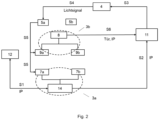
- eine schematische Darstellung eines erfindungsgemäßen Identifizierungsverfahrens.
- In der
Fig.1 wird eine Aufzugsanlage 1 gezeigt. In einem Aufzugsschacht 13 der Aufzugsanlage 1 mit mehreren Stockwerken oder Haltestationen 14 wird eine Aufzugskabine 8 durch ein Tragmittel 15 getragen, wobei in jeder Haltestation 14 eine Schachttür 7a oder 7b vorgesehen ist. Die Aufzugskabine 8 bewegt sich unter Steuerung von einer Steuereinheit 11 der Aufzugsanlage 1 vertikal im Aufzugsschacht 13, um Passagiere zwischen verschiedenen Stockwerken 14 zu transportieren. Die Aufzugskabine 8 weist eine linke 9a und eine rechte Kabinentür 9b auf, die einander gegenüber stehen aber in Struktur und in Funktion absolute identisch sind. Die Kabinentüren 9 werden dann beim Landen der Kabine 8 in einer Haltestation 14 mit den Schachttüren 7, die sich in der Haltestation befinden, gekoppelt, wodurch die Kabinentüre 9a oder 9b und die Schachttür 7a, 7b in der Haltestation immer zusammen und gleichzeitig geschlossen und geöffnet werden. - Innerhalb der Aufzugsanlage 1 besteht ein lokales Datennetz oder Netzwerk 2, das über einen Router oder ein Gateway 12 mit weiteren Netzwerken z.B. dem Internet verbunden ist. Wenn das Datennetz 2 ein drahtloses Netz ist, ist das Gateway oder der Router ebenfalls ein drahtloses Gerät. Durch das Datennetz 2 können alle Netzknoten 3 zur Kommunikation miteinander vernetzt werden. In diesem Ausführungsbeispiel bildet jede Haltestation 14 einen ersten Netzknoten 3a aus, während die Aufzugskabine 8 einen zweiten Netzknoten 3b des Datennetzes 2 ausbildet. Den Netzknoten 3a, 3b werden jeweils eine unterschiedliche Netzadresse, z.B. IP-Adresse, vom Router/Gateway 12 zugewiesen. Zwischen dem ersten Netzknoten 3a und dem zweiten Netzknoten 3b kann Information über ihre eigenen Netzadresse ausgetauscht werden. Dabei gehört die Schachtür 7a oder 7b zum ersten Netzknoten 3a, die Kabine 8 zu dem zweiten Netzknoten 3b. Da der Netzknoten 3b zwei gleiche Kabinentüren 9a und 9b umfasst aber nur eine einzige IP-Adresse besetzt, ist es in einer Installationsarbeit der Aufzugsanlage 1 für die Steuereinheit 11 erstmals unbekannt, welche der zwei Türen die linke Kabinentür 9a ist, und welche die rechte Kabinentür 9b ist.
- Zum Beleuchten des Aufzugsschachts 13 wird eine Lichtquelle 4 (z.B. LED-Lampe) in jeder Position, die für eine Schachttür 7 oder Ein-/Ausgang zur Kabine 8 zur Verfügung steht, im Schacht 13 angeordnet. Da die Steuereinheit 11 z.B. vom ersten Netzknoten 3a über Zuweisung von einer IP-Adresse bzw. die IP-Adresse informiert wird, erkennt die Steuereinheit 11, dass dieser Netzknoten 3a verfügbar oder aktiv ist. Zudem weiß die Steuereinheit 11 ebenfalls, auf welchem Stockwerk der Netzknoten 3a ist. Dann steuert die Steuereinheit 11 die Lichtquelle 4 so, dass nur die Lichtquellen 4, die an den verfügbaren Netzknoten 3a bzw. an den verfügbaren Schachtüren 7 sind, ein Lichtsignal 10 abstrahlen. Die Lichtquellen 4 werden z.B. durch digitale Signale, die von der Steuereinheit generiert sind, gesteuert, wobei einem verfügbaren Netzknoten ein digitales Signal "1" entspricht, ansonsten ein digitales Signal "0". Ein Beispiel wird durch eine untenstehende Tabelle angeführt. Eine verfügbare Schachtür wird durch ein digitales Signal "1" dargestellt, während ein digitales Signal "0" für eine nicht verfügbare Schachttür steht. Die Tür-Nummer stellen die konkreten einzelnen Schachttüren dar. Anstatt solcher Tür-Nummer kann auch die jeweiligen Produkt-Identitätsnummer solcher Türen verwendet werden. Die Tür-Nummern sind der Steuereinheit 11 bekannt.
Stockwerk Tür-Nummer Schachttür links Schachttür rechts 0 #1 1 0 1 #2, #3 1 1 2 #4 0 1 3 - 0 0 - Aus der Tabelle ist zu erkennen, dass für diese Aufzugsanlage 1 insgesamt vier Stockwerken gegeben sind. Dabei wird das dritte Stockwerk in
Fig.1 nicht dargestellt, weil in diesem Stockwerk keine Schachttür oder kein Ein-/Ausgang zur Kabine 8 vorgesehen ist. Deshalb sendet die Steuereinheit 11 zwei "0" Signale, so dass die zwei Lichtquellen 4 in diesem Stockwerk dunkel bleiben. - Zwei Lichtsensoren 5 sind auf dem Dach der Aufzugskabine 8 links und rechts angeordnet. Fährt die Kabine 8 entlang des Schachts 13 durch, können die Lichtsensoren 5 alle leuchtenden Lichtquellen 4 detektieren. Wenn z.B. der linke Lichtsensor 5a ein Lichtsignal 10 im Erdgeschoss detektiert hat, wird die Kabine 8 diese Schachtür #1 zu dem Lichtsensor 5a zuordnen. Danach informiert die Kabine 8 die Steuereinheit 11 über diese Zuordnung der Schachtür#1 (als am links) und die IP-Adresse dieses ersten Netzknotens 3a. Dann kann die Steuereinheit 11 die Schachtür #1 als eine linke Schachtür im Erdgeschoss anerkennen. In der gleichen Weise können die Schachtüren #2, #3 im ersten Stockwerk ebenfalls identifiziert werden, wobei die Schachtür #2 für links notiert wird, und die Schachtür #3 für rechts. Dabei können die Kabinentüren 9a, 9b ebenfalls identifiziert werden, dass die Kabinentür 9a die linke Kabinentür ist, und die Kabinentür 9b die rechte Kabinentür ist, weil sie mit den linken Schachttüren 7a und den rechten Schachttüren 7b zusammen geschaltet werden. Dafür braucht die Kabine 8 der Steuereinheit 11 zudem nur noch über die Tür-Nummer der Kabinentür 9a oder 9b zu informieren.
- In
Fig.2 wird ein erfindungsgemäßes Identifizierungsverfahren schematisch dargestellt. Wenn bei einer Installationsarbeit einer Aufzugsanlage 1, die inFig.1 vorgestellt worden ist, zwei Schachttüren 7a, 7b in einer Haltestation 14 oder zwei Kabinentüren 9a, 9b in einer Kabine 8 zueinander zu unterscheiden sind, können folgende Verfahrensschritten durchgeführt werden, wobei ein Verfahrensschritt mit "S" bezeichnet ist. - S1: ein Router 13 weist z.B. dem Netzknoten 3a eine IP-Adresse zu, wobei dieser Netzknoten 3a zwei Schachtüren 7a, 7b umfasst;
- S2: der Netzknoten 3a informiert die Steuereinheit 11 über seine IP-Adresse;
- S3: die Steuereinheit 11 aktiviert eine Lichtquelle 4 anhand dieser Information, damit ein Lichtsignal generiert wird;
- S4: z.B. ein Lichtsensor 5a, der als ein linker Sensor vorgesehen ist, detektiert das Lichtsignal;
- S5: die Kabine 8, die als ein anderer Netzknoten 3b gilt, hat die IP-Adresse des Netzknotens 3a ebenfalls erhalten. Die Kabine 8 ordnet die Schachtür 7a zu dem linken Sensor 5a. Dabei kann die Kabine 8 deren Kabinentüre 9a ebenfalls zu dem linken Sensor 5a zuordnen, weil diese Kabinentür 9a mit der Schachtür 7a gekoppelt wird;
- S6: die Kabine 8 teilt der Steuereinheit 11 mit, dass die Schachtür 7a und die Kabinentür 9a zu dem linken Sensor 5a zugeordnet sind. Zu der Mitteilung gehören ebenfalls die Tür-Nummer der Schachtür 7a und der Kabinentür 9a und die IP-Adresse der Netzknoten 3a und 3b.
- Angesichts der mitgeteilten Daten kann die Steuereinheit 11 in diesem Fall die zwei Schachtüren 7a, 7b bzw. die zwei Kabinentüren 9a, 9b jeweils als eine linke oder eine rechte Schachttür bzw. als eine linke oder eine rechte Kabinentür eindeutig identifizieren.
- Abschließend ist darauf hinzuweisen, dass Begriffe wie "aufweisend", "umfassend", etc. keine anderen Elemente oder Schritte ausschließen und Begriffe wie "eine" oder "ein" keine Vielzahl ausschließen. Ferner sei darauf hingewiesen, dass Merkmale oder Schritte, die mit Verweis auf eines der obigen Ausführungsbeispiele beschrieben worden sind, auch in Kombination mit anderen Merkmalen oder Schritten anderer oben beschriebener Ausführungsbeispiele verwendet werden können. Bezugszeichen in den Ansprüchen sind nicht als Einschränkung anzusehen.
Claims (14)
- Aufzugsanlage (1) mit einem Datennetz (2), das mindestens einen Netzknoten (3) aufweist, wobei der Netzknoten (3) eine Komponente (7, 9) der Aufzugsanlage (1) umfasst,
dadurch gekennzeichnet, dassdie Komponente (7, 9) des Netzknotens (3) derart identifizierbar ist, dass eine Steuereinheit (11) der Aufzugsanlage (1) eine Lichtquelle (4) der Aufzugsanlage (1) steuert, um ein Lichtsignal (10) zum Hinweis auf den Netzknoten (3) zu generieren,die Komponente (7, 9) einem Lichtsensor (5) der Aufzugsanlage (1) zuordenbar ist, wenn der Lichtsensor (5) das Lichtsignal (10) detektiert, unddie Zuordnung der Komponente (9) für die Steuereinheit (11) ermittelbar ist. - Aufzugsanlage (1) nach Anspruch 1, wobei
der Netzknoten (3) die Steuereinheit (11) über dessen Netzadresse und/oder die Netzadresse eines anderen Netzknotens informieren kann. - Aufzugsanlage (1) nach Anspruch 1 oder 2, wobeider Netzknoten (3) eine Haltestation (14) einer Kabine (8) der Aufzugsanlage (1) entspricht, wobei die Komponente eine Schachttür (7) ist, und/oderder Netzknoten (3) einer Kabine (8) der Aufzugsanlage (1) entspricht, wobei die Komponente eine Kabinentür (9) der Kabine (8) ist.
- Aufzugsanlage (1) nach Anspruch 3, wobei
die Haltestation (14) durch die Netzadresse des Netzknotens (3) ermittelbar ist. - Aufzugsanlage (1) nach einem der vorherigen Ansprüche, wobei
der Netzknoten (3) mindestens zwei Komponenten (7, 9) aufweist. - Aufzugsanlage (1) nach Anspruch 5, wobei
mindestens zwei Lichtsensoren (5a, 5b) vorgesehen sind, wobei einer der Lichtsensoren (5a, 5b) nach dessen Position gegenüber dem oder den anderen Lichtsensoren (5a, 5b) unterschiedlich identifizierbar ist. - Aufzugsanlage (1) nach einem der vorherigen Ansprüche, wobei
die Lichtquelle (4) einen Aufzugsschacht (13) und/oder eine Haltestation (14) der Aufzugsanlage (1) beleuchten kann. - Identifizierungsverfahren für eine Aufzugsanlage (1) mit einem Datennetz (2), das mindestens einen Netzknoten (3) aufweist, wobei der Netzknoten (3) mindestens eine Komponente (7, 9) der Aufzugsanlage (1) umfasst, bei demdie Komponente (7, 9) des Netzknotens (3) derart identifiziert wird, dass eine Lichtquelle (4) der Aufzugsanlage (1) durch eine Steuereinheit (11) der Aufzugsanlage (1) gesteuert wird, um ein Lichtsignal (10) zum Hinweis auf den Netzknoten (3) zu generieren,die Komponente (7, 9) einem Lichtsensor (5) der Aufzugsanlage (1) zuordnet wird, wenn der Lichtsensor (5) das Lichtsignal (10) detektiert, unddie Zuordnung der Komponente (7, 9) der Steuereinheit (11) mitgeteilt wird,
- Identifizierungsverfahren nach Anspruch 8, bei dem
die Steuereinheit (11) vom Netzknoten (3) über dessen Netzadresse und/oder die Netzadresse eines anderen Netzknotens informiert wird. - Identifizierungsverfahren nach Anspruch 9, bei demder Netzknoten (3) durch eine Haltestation (14) einer Kabine (8) der Aufzugsanlage (1) ausgebildet wird, wobei die Komponente eine Schachttür (7) ist, und/oderder Netzknoten (3) durch eine Kabine (8) der Aufzugsanlage (1) ausgebildet wird, wobei die Komponente eine Kabinentür (9) der Kabine (8) ist.
- Identifizierungsverfahren nach Anspruch 10, bei dem
die Haltestation (14) durch die Netzadresse des Netzknotens (3) ermittelt wird. - Identifizierungsverfahren nach nach Anspruch einem der vorherigen Ansprüche 8 bis 11, bei dem
mindestens zwei Komponenten (7, 9) des Netzknotens (3) vorgesehen werden. - Identifizierungsverfahren nach Anspruch 12, bei dem
mindestens zwei Lichtsensoren (5a, 5b) vorgesehen werden, wobei einer der Lichtsensoren (5a, 5b) nach dessen Position gegenüber dem oder den anderen Lichtsensoren (5a, 5b) unterschiedlich identifiziert wird. - Identifizierungsverfahren nach einem der Ansprüche 8 bis 13, bei dem
ein Aufzugsschacht (13) und/oder eine Haltestation (14) der Aufzugsanlage (1) durch die Lichtquelle (4) beleuchtet wird.
Applications Claiming Priority (2)
| Application Number | Priority Date | Filing Date | Title |
|---|---|---|---|
| EP20216918 | 2020-12-23 | ||
| PCT/EP2021/086380 WO2022136139A1 (de) | 2020-12-23 | 2021-12-17 | Aufzugsanlage und identifizierungsverfahren |
Publications (2)
| Publication Number | Publication Date |
|---|---|
| EP4267502A1 EP4267502A1 (de) | 2023-11-01 |
| EP4267502B1 true EP4267502B1 (de) | 2024-10-30 |
Family
ID=74186429
Family Applications (1)
| Application Number | Title | Priority Date | Filing Date |
|---|---|---|---|
| EP21840560.3A Active EP4267502B1 (de) | 2020-12-23 | 2021-12-17 | Aufzugsanlage und identifizierungsverfahren |
Country Status (4)
| Country | Link |
|---|---|
| US (1) | US20240043242A1 (de) |
| EP (1) | EP4267502B1 (de) |
| CN (1) | CN116685547B (de) |
| WO (1) | WO2022136139A1 (de) |
Family Cites Families (6)
| Publication number | Priority date | Publication date | Assignee | Title |
|---|---|---|---|---|
| GB2364991B (en) * | 2000-05-05 | 2004-05-26 | Read Holdings Ltd | Lift control system |
| EP3030510A1 (de) * | 2013-08-09 | 2016-06-15 | Inventio AG | Kommunikationsverfahren und -vorrichtung für eine aufzugsanlage |
| EP3333110B1 (de) * | 2016-12-09 | 2022-05-11 | Otis Elevator Company | Sicherheitssystem für einen aufzug, aufzugsystem und verfahren zum betrieb eines aufzugsystems |
| AT520568A1 (de) * | 2017-10-17 | 2019-05-15 | View Promotion Gmbh | Verfahren zur Überwachung einer Aufzugskabine |
| US11577932B2 (en) * | 2018-07-26 | 2023-02-14 | Otis Elevator Company | Elevator component inspection systems |
| CN111591842A (zh) * | 2020-05-30 | 2020-08-28 | 陕西泓源特种设备研究院有限公司 | 一种基于智能网关的语音控制电梯方法及系统 |
-
2021
- 2021-12-17 US US18/257,888 patent/US20240043242A1/en active Pending
- 2021-12-17 EP EP21840560.3A patent/EP4267502B1/de active Active
- 2021-12-17 CN CN202180087095.3A patent/CN116685547B/zh active Active
- 2021-12-17 WO PCT/EP2021/086380 patent/WO2022136139A1/de not_active Ceased
Also Published As
| Publication number | Publication date |
|---|---|
| CN116685547B (zh) | 2026-03-27 |
| EP4267502A1 (de) | 2023-11-01 |
| US20240043242A1 (en) | 2024-02-08 |
| CN116685547A (zh) | 2023-09-01 |
| WO2022136139A1 (de) | 2022-06-30 |
Similar Documents
| Publication | Publication Date | Title |
|---|---|---|
| EP2238067B1 (de) | Aufzugsanlage, verfahren zum bedienen einer solchen aufzugsanlage und verfahren zum nachrüsten einer bestehenden aufzugsanlage zu einer solchen aufzugsanlage | |
| WO2001072621A1 (de) | Zielrufsteuerung für aufzüge | |
| EP1565396A1 (de) | Verfahren zur steuerung einer aufzuganlage sowie aufzuganlage zur durchführung des verfahrens | |
| EP1371596A1 (de) | Sicherheitseinrichtung für eine Aufzugsgruppe | |
| DE102014220966A1 (de) | Verfahren zum Betreiben einer Transportanlage sowie entsprechende Transportanlage | |
| EP3261971A1 (de) | Verfahren zum betreiben eines aufzugsystems mit mehreren schächten und mehreren kabinen | |
| EP3233697B1 (de) | Verfahren zum betreiben eines elektronischen sicherheitssystems mit temporären teilnehmern | |
| EP3030510A1 (de) | Kommunikationsverfahren und -vorrichtung für eine aufzugsanlage | |
| WO2008110631A1 (de) | Anzeigevorrichtung und kommunikationsverfahren für ein aufzugsystem | |
| EP3468905B1 (de) | Personentransportanlage mit zentraler steuereinheit und mehreren feldgeräten, welche mit durch karenzzeiten priorisierte datentelegramme kommunizieren | |
| EP2545751A1 (de) | Bus -gebäudetechniksystem mit daisy-chain topologie | |
| WO2020094437A1 (de) | Aufzugsanlage und verfahren zum betrieb einer aufzugsanlage mit einer hilfseinrichtung | |
| EP3621911A1 (de) | Modernisierung einer aufzuggruppe | |
| EP3233698B1 (de) | Verfahren zum betreiben eines elektronischen sicherheitssystems mit temporären teilnehmern | |
| WO2018202736A1 (de) | Steuerungssystem für eine aufzugsanlage, aufzugsanlage und verfahren zum steuern einer aufzugsanlage | |
| WO2019228911A1 (de) | Automatisierungssystem, betriebsverfahren für automatisierungssystem und computerprogrammprodukt | |
| EP3251469B1 (de) | Verfahren zum betreiben von geräten in einem beleuchtungssystem | |
| EP4267502A1 (de) | Aufzugsanlage und identifizierungsverfahren | |
| DE2202671A1 (de) | Steuerung fuer Fahrstuhlanlagen od.dgl. | |
| EP3001647A1 (de) | Verfahren zum Aufbau einer gesicherten Kommunikationsverbindung, Kommunikationsgerät und Verbindungssteuerungseinheit | |
| EP2008403B1 (de) | Verfahren zum installieren eines funksystems in einem gebäude | |
| EP1847499B1 (de) | Verfahren zur Einstellung der Stockwerkszuordnungen einer Vielzahl von Bedieneinheiten einer Aufzugsanlage | |
| EP1628273B1 (de) | Verfahren zur Inbetriebsetzung von funkbasierten Gefahrenmeldesystemen | |
| DE102020005856A1 (de) | Verfahren zum Betreiben einer technischen Anlage und technische Anlage | |
| WO2009132698A1 (de) | Aufzugsanlage und rufsteuerung zur verwendung in einer aufzugsanlage |
Legal Events
| Date | Code | Title | Description |
|---|---|---|---|
| STAA | Information on the status of an ep patent application or granted ep patent |
Free format text: STATUS: UNKNOWN |
|
| STAA | Information on the status of an ep patent application or granted ep patent |
Free format text: STATUS: THE INTERNATIONAL PUBLICATION HAS BEEN MADE |
|
| PUAI | Public reference made under article 153(3) epc to a published international application that has entered the european phase |
Free format text: ORIGINAL CODE: 0009012 |
|
| STAA | Information on the status of an ep patent application or granted ep patent |
Free format text: STATUS: REQUEST FOR EXAMINATION WAS MADE |
|
| 17P | Request for examination filed |
Effective date: 20230601 |
|
| AK | Designated contracting states |
Kind code of ref document: A1 Designated state(s): AL AT BE BG CH CY CZ DE DK EE ES FI FR GB GR HR HU IE IS IT LI LT LU LV MC MK MT NL NO PL PT RO RS SE SI SK SM TR |
|
| DAV | Request for validation of the european patent (deleted) | ||
| DAX | Request for extension of the european patent (deleted) | ||
| GRAP | Despatch of communication of intention to grant a patent |
Free format text: ORIGINAL CODE: EPIDOSNIGR1 |
|
| STAA | Information on the status of an ep patent application or granted ep patent |
Free format text: STATUS: GRANT OF PATENT IS INTENDED |
|
| GRAS | Grant fee paid |
Free format text: ORIGINAL CODE: EPIDOSNIGR3 |
|
| INTG | Intention to grant announced |
Effective date: 20240816 |
|
| GRAA | (expected) grant |
Free format text: ORIGINAL CODE: 0009210 |
|
| STAA | Information on the status of an ep patent application or granted ep patent |
Free format text: STATUS: THE PATENT HAS BEEN GRANTED |
|
| AK | Designated contracting states |
Kind code of ref document: B1 Designated state(s): AL AT BE BG CH CY CZ DE DK EE ES FI FR GB GR HR HU IE IS IT LI LT LU LV MC MK MT NL NO PL PT RO RS SE SI SK SM TR |
|
| REG | Reference to a national code |
Ref country code: GB Ref legal event code: FG4D Free format text: NOT ENGLISH |
|
| REG | Reference to a national code |
Ref country code: CH Ref legal event code: EP |
|
| REG | Reference to a national code |
Ref country code: DE Ref legal event code: R096 Ref document number: 502021005668 Country of ref document: DE |
|
| REG | Reference to a national code |
Ref country code: IE Ref legal event code: FG4D Free format text: LANGUAGE OF EP DOCUMENT: GERMAN |
|
| REG | Reference to a national code |
Ref country code: LT Ref legal event code: MG9D |
|
| REG | Reference to a national code |
Ref country code: NL Ref legal event code: MP Effective date: 20241030 |
|
| PG25 | Lapsed in a contracting state [announced via postgrant information from national office to epo] |
Ref country code: HR Free format text: LAPSE BECAUSE OF FAILURE TO SUBMIT A TRANSLATION OF THE DESCRIPTION OR TO PAY THE FEE WITHIN THE PRESCRIBED TIME-LIMIT Effective date: 20241030 Ref country code: PT Free format text: LAPSE BECAUSE OF FAILURE TO SUBMIT A TRANSLATION OF THE DESCRIPTION OR TO PAY THE FEE WITHIN THE PRESCRIBED TIME-LIMIT Effective date: 20250228 Ref country code: IS Free format text: LAPSE BECAUSE OF FAILURE TO SUBMIT A TRANSLATION OF THE DESCRIPTION OR TO PAY THE FEE WITHIN THE PRESCRIBED TIME-LIMIT Effective date: 20250228 |
|
| PG25 | Lapsed in a contracting state [announced via postgrant information from national office to epo] |
Ref country code: NL Free format text: LAPSE BECAUSE OF FAILURE TO SUBMIT A TRANSLATION OF THE DESCRIPTION OR TO PAY THE FEE WITHIN THE PRESCRIBED TIME-LIMIT Effective date: 20241030 Ref country code: FI Free format text: LAPSE BECAUSE OF FAILURE TO SUBMIT A TRANSLATION OF THE DESCRIPTION OR TO PAY THE FEE WITHIN THE PRESCRIBED TIME-LIMIT Effective date: 20241030 |
|
| PG25 | Lapsed in a contracting state [announced via postgrant information from national office to epo] |
Ref country code: BG Free format text: LAPSE BECAUSE OF FAILURE TO SUBMIT A TRANSLATION OF THE DESCRIPTION OR TO PAY THE FEE WITHIN THE PRESCRIBED TIME-LIMIT Effective date: 20241030 |
|
| PG25 | Lapsed in a contracting state [announced via postgrant information from national office to epo] |
Ref country code: ES Free format text: LAPSE BECAUSE OF FAILURE TO SUBMIT A TRANSLATION OF THE DESCRIPTION OR TO PAY THE FEE WITHIN THE PRESCRIBED TIME-LIMIT Effective date: 20241030 |
|
| PG25 | Lapsed in a contracting state [announced via postgrant information from national office to epo] |
Ref country code: NO Free format text: LAPSE BECAUSE OF FAILURE TO SUBMIT A TRANSLATION OF THE DESCRIPTION OR TO PAY THE FEE WITHIN THE PRESCRIBED TIME-LIMIT Effective date: 20250130 |
|
| PG25 | Lapsed in a contracting state [announced via postgrant information from national office to epo] |
Ref country code: LV Free format text: LAPSE BECAUSE OF FAILURE TO SUBMIT A TRANSLATION OF THE DESCRIPTION OR TO PAY THE FEE WITHIN THE PRESCRIBED TIME-LIMIT Effective date: 20241030 Ref country code: GR Free format text: LAPSE BECAUSE OF FAILURE TO SUBMIT A TRANSLATION OF THE DESCRIPTION OR TO PAY THE FEE WITHIN THE PRESCRIBED TIME-LIMIT Effective date: 20250131 |
|
| PG25 | Lapsed in a contracting state [announced via postgrant information from national office to epo] |
Ref country code: PL Free format text: LAPSE BECAUSE OF FAILURE TO SUBMIT A TRANSLATION OF THE DESCRIPTION OR TO PAY THE FEE WITHIN THE PRESCRIBED TIME-LIMIT Effective date: 20241030 |
|
| PG25 | Lapsed in a contracting state [announced via postgrant information from national office to epo] |
Ref country code: RS Free format text: LAPSE BECAUSE OF FAILURE TO SUBMIT A TRANSLATION OF THE DESCRIPTION OR TO PAY THE FEE WITHIN THE PRESCRIBED TIME-LIMIT Effective date: 20250130 |
|
| PG25 | Lapsed in a contracting state [announced via postgrant information from national office to epo] |
Ref country code: SM Free format text: LAPSE BECAUSE OF FAILURE TO SUBMIT A TRANSLATION OF THE DESCRIPTION OR TO PAY THE FEE WITHIN THE PRESCRIBED TIME-LIMIT Effective date: 20241030 |
|
| PG25 | Lapsed in a contracting state [announced via postgrant information from national office to epo] |
Ref country code: MC Free format text: LAPSE BECAUSE OF FAILURE TO SUBMIT A TRANSLATION OF THE DESCRIPTION OR TO PAY THE FEE WITHIN THE PRESCRIBED TIME-LIMIT Effective date: 20241030 |
|
| PG25 | Lapsed in a contracting state [announced via postgrant information from national office to epo] |
Ref country code: DK Free format text: LAPSE BECAUSE OF FAILURE TO SUBMIT A TRANSLATION OF THE DESCRIPTION OR TO PAY THE FEE WITHIN THE PRESCRIBED TIME-LIMIT Effective date: 20241030 |
|
| PG25 | Lapsed in a contracting state [announced via postgrant information from national office to epo] |
Ref country code: EE Free format text: LAPSE BECAUSE OF FAILURE TO SUBMIT A TRANSLATION OF THE DESCRIPTION OR TO PAY THE FEE WITHIN THE PRESCRIBED TIME-LIMIT Effective date: 20241030 |
|
| PG25 | Lapsed in a contracting state [announced via postgrant information from national office to epo] |
Ref country code: RO Free format text: LAPSE BECAUSE OF FAILURE TO SUBMIT A TRANSLATION OF THE DESCRIPTION OR TO PAY THE FEE WITHIN THE PRESCRIBED TIME-LIMIT Effective date: 20241030 |
|
| PG25 | Lapsed in a contracting state [announced via postgrant information from national office to epo] |
Ref country code: SK Free format text: LAPSE BECAUSE OF FAILURE TO SUBMIT A TRANSLATION OF THE DESCRIPTION OR TO PAY THE FEE WITHIN THE PRESCRIBED TIME-LIMIT Effective date: 20241030 |
|
| PG25 | Lapsed in a contracting state [announced via postgrant information from national office to epo] |
Ref country code: CZ Free format text: LAPSE BECAUSE OF FAILURE TO SUBMIT A TRANSLATION OF THE DESCRIPTION OR TO PAY THE FEE WITHIN THE PRESCRIBED TIME-LIMIT Effective date: 20241030 |
|
| PG25 | Lapsed in a contracting state [announced via postgrant information from national office to epo] |
Ref country code: IT Free format text: LAPSE BECAUSE OF FAILURE TO SUBMIT A TRANSLATION OF THE DESCRIPTION OR TO PAY THE FEE WITHIN THE PRESCRIBED TIME-LIMIT Effective date: 20241030 |
|
| REG | Reference to a national code |
Ref country code: DE Ref legal event code: R097 Ref document number: 502021005668 Country of ref document: DE |
|
| PG25 | Lapsed in a contracting state [announced via postgrant information from national office to epo] |
Ref country code: LU Free format text: LAPSE BECAUSE OF NON-PAYMENT OF DUE FEES Effective date: 20241217 |
|
| PLBE | No opposition filed within time limit |
Free format text: ORIGINAL CODE: 0009261 |
|
| STAA | Information on the status of an ep patent application or granted ep patent |
Free format text: STATUS: NO OPPOSITION FILED WITHIN TIME LIMIT |
|
| PG25 | Lapsed in a contracting state [announced via postgrant information from national office to epo] |
Ref country code: SE Free format text: LAPSE BECAUSE OF FAILURE TO SUBMIT A TRANSLATION OF THE DESCRIPTION OR TO PAY THE FEE WITHIN THE PRESCRIBED TIME-LIMIT Effective date: 20241030 |
|
| 26N | No opposition filed |
Effective date: 20250731 |
|
| REG | Reference to a national code |
Ref country code: BE Ref legal event code: MM Effective date: 20241231 |
|
| PG25 | Lapsed in a contracting state [announced via postgrant information from national office to epo] |
Ref country code: BE Free format text: LAPSE BECAUSE OF NON-PAYMENT OF DUE FEES Effective date: 20241231 |
|
| PG25 | Lapsed in a contracting state [announced via postgrant information from national office to epo] |
Ref country code: IE Free format text: LAPSE BECAUSE OF NON-PAYMENT OF DUE FEES Effective date: 20241217 |
|
| REG | Reference to a national code |
Ref country code: CH Ref legal event code: U11 Free format text: ST27 STATUS EVENT CODE: U-0-0-U10-U11 (AS PROVIDED BY THE NATIONAL OFFICE) Effective date: 20260101 |
|
| PGFP | Annual fee paid to national office [announced via postgrant information from national office to epo] |
Ref country code: GB Payment date: 20251223 Year of fee payment: 5 |
|
| PGFP | Annual fee paid to national office [announced via postgrant information from national office to epo] |
Ref country code: AT Payment date: 20260113 Year of fee payment: 5 |
|
| PGFP | Annual fee paid to national office [announced via postgrant information from national office to epo] |
Ref country code: FR Payment date: 20251230 Year of fee payment: 5 |
|
| PGFP | Annual fee paid to national office [announced via postgrant information from national office to epo] |
Ref country code: DE Payment date: 20251229 Year of fee payment: 5 |
|
| PGFP | Annual fee paid to national office [announced via postgrant information from national office to epo] |
Ref country code: CH Payment date: 20260101 Year of fee payment: 5 |