EP4266437A1 - Élément d'accumulateur d'énergie et procédé de fabrication - Google Patents
Élément d'accumulateur d'énergie et procédé de fabrication Download PDFInfo
- Publication number
- EP4266437A1 EP4266437A1 EP22169512.5A EP22169512A EP4266437A1 EP 4266437 A1 EP4266437 A1 EP 4266437A1 EP 22169512 A EP22169512 A EP 22169512A EP 4266437 A1 EP4266437 A1 EP 4266437A1
- Authority
- EP
- European Patent Office
- Prior art keywords
- current collector
- edge
- contact plate
- energy storage
- electrode
- Prior art date
- Legal status (The legal status is an assumption and is not a legal conclusion. Google has not performed a legal analysis and makes no representation as to the accuracy of the status listed.)
- Pending
Links
- 238000004146 energy storage Methods 0.000 title claims abstract description 144
- 238000004519 manufacturing process Methods 0.000 title claims description 13
- 239000002131 composite material Substances 0.000 claims abstract description 71
- 239000012528 membrane Substances 0.000 claims abstract description 22
- 239000007773 negative electrode material Substances 0.000 claims abstract description 7
- 239000007774 positive electrode material Substances 0.000 claims abstract description 7
- PXHVJJICTQNCMI-UHFFFAOYSA-N Nickel Chemical compound [Ni] PXHVJJICTQNCMI-UHFFFAOYSA-N 0.000 claims description 53
- RYGMFSIKBFXOCR-UHFFFAOYSA-N Copper Chemical compound [Cu] RYGMFSIKBFXOCR-UHFFFAOYSA-N 0.000 claims description 47
- 229910052782 aluminium Inorganic materials 0.000 claims description 41
- XAGFODPZIPBFFR-UHFFFAOYSA-N aluminium Chemical compound [Al] XAGFODPZIPBFFR-UHFFFAOYSA-N 0.000 claims description 41
- 239000010949 copper Substances 0.000 claims description 41
- 238000003466 welding Methods 0.000 claims description 40
- 239000000463 material Substances 0.000 claims description 35
- 239000011324 bead Substances 0.000 claims description 34
- 229910052802 copper Inorganic materials 0.000 claims description 29
- 229910052759 nickel Inorganic materials 0.000 claims description 26
- 229910000838 Al alloy Inorganic materials 0.000 claims description 22
- 150000001875 compounds Chemical class 0.000 claims description 19
- 239000007772 electrode material Substances 0.000 claims description 16
- 229910000881 Cu alloy Inorganic materials 0.000 claims description 15
- 238000005266 casting Methods 0.000 claims description 15
- 229910000831 Steel Inorganic materials 0.000 claims description 12
- 239000010959 steel Substances 0.000 claims description 12
- 229910001220 stainless steel Inorganic materials 0.000 claims description 11
- 229910000990 Ni alloy Inorganic materials 0.000 claims description 10
- RTAQQCXQSZGOHL-UHFFFAOYSA-N Titanium Chemical compound [Ti] RTAQQCXQSZGOHL-UHFFFAOYSA-N 0.000 claims description 10
- 239000004033 plastic Substances 0.000 claims description 9
- 229920003023 plastic Polymers 0.000 claims description 9
- 239000010935 stainless steel Substances 0.000 claims description 7
- 239000010936 titanium Substances 0.000 claims description 7
- 229910001069 Ti alloy Inorganic materials 0.000 claims description 6
- 229910052719 titanium Inorganic materials 0.000 claims description 6
- 230000000284 resting effect Effects 0.000 claims description 4
- 238000010276 construction Methods 0.000 abstract description 2
- 210000004027 cell Anatomy 0.000 description 99
- 210000000352 storage cell Anatomy 0.000 description 47
- 210000004379 membrane Anatomy 0.000 description 21
- 229910001416 lithium ion Inorganic materials 0.000 description 18
- 238000004804 winding Methods 0.000 description 16
- 229910052751 metal Inorganic materials 0.000 description 13
- 239000002184 metal Substances 0.000 description 13
- 229910045601 alloy Inorganic materials 0.000 description 12
- 239000000956 alloy Substances 0.000 description 12
- 239000003792 electrolyte Substances 0.000 description 12
- 238000013461 design Methods 0.000 description 11
- 229910052744 lithium Inorganic materials 0.000 description 10
- WHXSMMKQMYFTQS-UHFFFAOYSA-N Lithium Chemical compound [Li] WHXSMMKQMYFTQS-UHFFFAOYSA-N 0.000 description 9
- 239000011149 active material Substances 0.000 description 9
- OKTJSMMVPCPJKN-UHFFFAOYSA-N Carbon Chemical compound [C] OKTJSMMVPCPJKN-UHFFFAOYSA-N 0.000 description 8
- 239000004020 conductor Substances 0.000 description 8
- 239000007789 gas Substances 0.000 description 8
- 238000000034 method Methods 0.000 description 8
- 230000003313 weakening effect Effects 0.000 description 8
- 230000008901 benefit Effects 0.000 description 7
- 239000002245 particle Substances 0.000 description 7
- 239000004411 aluminium Substances 0.000 description 6
- 239000011888 foil Substances 0.000 description 6
- -1 lithium hexafluorophosphate Chemical compound 0.000 description 6
- 229910052799 carbon Inorganic materials 0.000 description 5
- 239000011883 electrode binding agent Substances 0.000 description 5
- 229910003336 CuNi Inorganic materials 0.000 description 4
- 241001295925 Gegenes Species 0.000 description 4
- 229910001030 Iron–nickel alloy Inorganic materials 0.000 description 4
- 229910003322 NiCu Inorganic materials 0.000 description 4
- 239000002033 PVDF binder Substances 0.000 description 4
- VNNRSPGTAMTISX-UHFFFAOYSA-N chromium nickel Chemical compound [Cr].[Ni] VNNRSPGTAMTISX-UHFFFAOYSA-N 0.000 description 4
- 238000005259 measurement Methods 0.000 description 4
- 239000000203 mixture Substances 0.000 description 4
- 229910001120 nichrome Inorganic materials 0.000 description 4
- 239000002985 plastic film Substances 0.000 description 4
- 229920006255 plastic film Polymers 0.000 description 4
- 229920002981 polyvinylidene fluoride Polymers 0.000 description 4
- 238000004382 potting Methods 0.000 description 4
- 229910052710 silicon Inorganic materials 0.000 description 4
- 239000010703 silicon Substances 0.000 description 4
- HBBGRARXTFLTSG-UHFFFAOYSA-N Lithium ion Chemical compound [Li+] HBBGRARXTFLTSG-UHFFFAOYSA-N 0.000 description 3
- 239000000654 additive Substances 0.000 description 3
- 239000002390 adhesive tape Substances 0.000 description 3
- 238000011161 development Methods 0.000 description 3
- 230000018109 developmental process Effects 0.000 description 3
- 150000002500 ions Chemical class 0.000 description 3
- 229910003002 lithium salt Inorganic materials 0.000 description 3
- 159000000002 lithium salts Chemical class 0.000 description 3
- 150000002739 metals Chemical class 0.000 description 3
- 238000007789 sealing Methods 0.000 description 3
- 229920002134 Carboxymethyl cellulose Polymers 0.000 description 2
- 229910012851 LiCoO 2 Inorganic materials 0.000 description 2
- 229910010707 LiFePO 4 Inorganic materials 0.000 description 2
- 229910013716 LiNi Inorganic materials 0.000 description 2
- 229910013870 LiPF 6 Inorganic materials 0.000 description 2
- XUIMIQQOPSSXEZ-UHFFFAOYSA-N Silicon Chemical compound [Si] XUIMIQQOPSSXEZ-UHFFFAOYSA-N 0.000 description 2
- ATJFFYVFTNAWJD-UHFFFAOYSA-N Tin Chemical compound [Sn] ATJFFYVFTNAWJD-UHFFFAOYSA-N 0.000 description 2
- 229910052787 antimony Inorganic materials 0.000 description 2
- WATWJIUSRGPENY-UHFFFAOYSA-N antimony atom Chemical compound [Sb] WATWJIUSRGPENY-UHFFFAOYSA-N 0.000 description 2
- 230000015572 biosynthetic process Effects 0.000 description 2
- 239000001768 carboxy methyl cellulose Substances 0.000 description 2
- 235000010948 carboxy methyl cellulose Nutrition 0.000 description 2
- 239000008112 carboxymethyl-cellulose Substances 0.000 description 2
- 239000006258 conductive agent Substances 0.000 description 2
- 238000012983 electrochemical energy storage Methods 0.000 description 2
- 239000004744 fabric Substances 0.000 description 2
- 239000010439 graphite Substances 0.000 description 2
- 229910002804 graphite Inorganic materials 0.000 description 2
- 229910003473 lithium bis(trifluoromethanesulfonyl)imide Inorganic materials 0.000 description 2
- VDVLPSWVDYJFRW-UHFFFAOYSA-N lithium;bis(fluorosulfonyl)azanide Chemical compound [Li+].FS(=O)(=O)[N-]S(F)(=O)=O VDVLPSWVDYJFRW-UHFFFAOYSA-N 0.000 description 2
- QSZMZKBZAYQGRS-UHFFFAOYSA-N lithium;bis(trifluoromethylsulfonyl)azanide Chemical compound [Li+].FC(F)(F)S(=O)(=O)[N-]S(=O)(=O)C(F)(F)F QSZMZKBZAYQGRS-UHFFFAOYSA-N 0.000 description 2
- 239000011159 matrix material Substances 0.000 description 2
- 239000007769 metal material Substances 0.000 description 2
- 239000003960 organic solvent Substances 0.000 description 2
- 229920001707 polybutylene terephthalate Polymers 0.000 description 2
- 229920000139 polyethylene terephthalate Polymers 0.000 description 2
- 239000005020 polyethylene terephthalate Substances 0.000 description 2
- 230000008569 process Effects 0.000 description 2
- 239000000126 substance Substances 0.000 description 2
- 229910052718 tin Inorganic materials 0.000 description 2
- UNILWMWFPHPYOR-KXEYIPSPSA-M 1-[6-[2-[3-[3-[3-[2-[2-[3-[[2-[2-[[(2r)-1-[[2-[[(2r)-1-[3-[2-[2-[3-[[2-(2-amino-2-oxoethoxy)acetyl]amino]propoxy]ethoxy]ethoxy]propylamino]-3-hydroxy-1-oxopropan-2-yl]amino]-2-oxoethyl]amino]-3-[(2r)-2,3-di(hexadecanoyloxy)propyl]sulfanyl-1-oxopropan-2-yl Chemical compound O=C1C(SCCC(=O)NCCCOCCOCCOCCCNC(=O)COCC(=O)N[C@@H](CSC[C@@H](COC(=O)CCCCCCCCCCCCCCC)OC(=O)CCCCCCCCCCCCCCC)C(=O)NCC(=O)N[C@H](CO)C(=O)NCCCOCCOCCOCCCNC(=O)COCC(N)=O)CC(=O)N1CCNC(=O)CCCCCN\1C2=CC=C(S([O-])(=O)=O)C=C2CC/1=C/C=C/C=C/C1=[N+](CC)C2=CC=C(S([O-])(=O)=O)C=C2C1 UNILWMWFPHPYOR-KXEYIPSPSA-M 0.000 description 1
- 229910018072 Al 2 O 3 Inorganic materials 0.000 description 1
- BTBUEUYNUDRHOZ-UHFFFAOYSA-N Borate Chemical compound [O-]B([O-])[O-] BTBUEUYNUDRHOZ-UHFFFAOYSA-N 0.000 description 1
- 229920000049 Carbon (fiber) Polymers 0.000 description 1
- 241000219504 Caryophyllales Species 0.000 description 1
- 229910013063 LiBF 4 Inorganic materials 0.000 description 1
- 239000004642 Polyimide Substances 0.000 description 1
- 239000004743 Polypropylene Substances 0.000 description 1
- 229910004298 SiO 2 Inorganic materials 0.000 description 1
- VYPSYNLAJGMNEJ-UHFFFAOYSA-N Silicium dioxide Chemical compound O=[Si]=O VYPSYNLAJGMNEJ-UHFFFAOYSA-N 0.000 description 1
- SFKQQYOXXWIJSA-UHFFFAOYSA-N [Li+].[O--].[O--].[O--].[O--].[O--].[Al+3].[Mn++].[Co++].[Ni++] Chemical compound [Li+].[O--].[O--].[O--].[O--].[O--].[Al+3].[Mn++].[Co++].[Ni++] SFKQQYOXXWIJSA-UHFFFAOYSA-N 0.000 description 1
- 239000002253 acid Substances 0.000 description 1
- 230000000996 additive effect Effects 0.000 description 1
- 238000004026 adhesive bonding Methods 0.000 description 1
- 239000011230 binding agent Substances 0.000 description 1
- OJIJEKBXJYRIBZ-UHFFFAOYSA-N cadmium nickel Chemical group [Ni].[Cd] OJIJEKBXJYRIBZ-UHFFFAOYSA-N 0.000 description 1
- 239000004917 carbon fiber Substances 0.000 description 1
- 239000002041 carbon nanotube Substances 0.000 description 1
- 229910021393 carbon nanotube Inorganic materials 0.000 description 1
- 239000002388 carbon-based active material Substances 0.000 description 1
- 239000003575 carbonaceous material Substances 0.000 description 1
- BVKZGUZCCUSVTD-UHFFFAOYSA-N carbonic acid Chemical compound OC(O)=O BVKZGUZCCUSVTD-UHFFFAOYSA-N 0.000 description 1
- 239000000919 ceramic Substances 0.000 description 1
- 238000006243 chemical reaction Methods 0.000 description 1
- 150000004292 cyclic ethers Chemical class 0.000 description 1
- 230000001419 dependent effect Effects 0.000 description 1
- 238000007599 discharging Methods 0.000 description 1
- 238000009826 distribution Methods 0.000 description 1
- 230000000694 effects Effects 0.000 description 1
- 239000011262 electrochemically active material Substances 0.000 description 1
- 238000003411 electrode reaction Methods 0.000 description 1
- 150000002148 esters Chemical class 0.000 description 1
- 150000002170 ethers Chemical class 0.000 description 1
- 230000017525 heat dissipation Effects 0.000 description 1
- 238000009434 installation Methods 0.000 description 1
- 239000012212 insulator Substances 0.000 description 1
- 238000009830 intercalation Methods 0.000 description 1
- 238000002372 labelling Methods 0.000 description 1
- 238000003475 lamination Methods 0.000 description 1
- 239000007788 liquid Substances 0.000 description 1
- 229910000625 lithium cobalt oxide Inorganic materials 0.000 description 1
- GELKBWJHTRAYNV-UHFFFAOYSA-K lithium iron phosphate Chemical compound [Li+].[Fe+2].[O-]P([O-])([O-])=O GELKBWJHTRAYNV-UHFFFAOYSA-K 0.000 description 1
- 229910021450 lithium metal oxide Inorganic materials 0.000 description 1
- 229910001496 lithium tetrafluoroborate Inorganic materials 0.000 description 1
- CJYZTOPVWURGAI-UHFFFAOYSA-N lithium;manganese;manganese(3+);oxygen(2-) Chemical compound [Li+].[O-2].[O-2].[O-2].[O-2].[Mn].[Mn+3] CJYZTOPVWURGAI-UHFFFAOYSA-N 0.000 description 1
- VGYDTVNNDKLMHX-UHFFFAOYSA-N lithium;manganese;nickel;oxocobalt Chemical compound [Li].[Mn].[Ni].[Co]=O VGYDTVNNDKLMHX-UHFFFAOYSA-N 0.000 description 1
- BFZPBUKRYWOWDV-UHFFFAOYSA-N lithium;oxido(oxo)cobalt Chemical compound [Li+].[O-][Co]=O BFZPBUKRYWOWDV-UHFFFAOYSA-N 0.000 description 1
- 230000007257 malfunction Effects 0.000 description 1
- 239000011572 manganese Substances 0.000 description 1
- 229910052987 metal hydride Inorganic materials 0.000 description 1
- 239000006262 metallic foam Substances 0.000 description 1
- 229910001317 nickel manganese cobalt oxide (NMC) Inorganic materials 0.000 description 1
- 150000002825 nitriles Chemical class 0.000 description 1
- 239000004745 nonwoven fabric Substances 0.000 description 1
- 150000005677 organic carbonates Chemical class 0.000 description 1
- 230000003647 oxidation Effects 0.000 description 1
- 238000007254 oxidation reaction Methods 0.000 description 1
- 230000036961 partial effect Effects 0.000 description 1
- 230000002093 peripheral effect Effects 0.000 description 1
- 150000003013 phosphoric acid derivatives Chemical class 0.000 description 1
- 229920001643 poly(ether ketone) Polymers 0.000 description 1
- 229920003223 poly(pyromellitimide-1,4-diphenyl ether) Polymers 0.000 description 1
- 229920000058 polyacrylate Polymers 0.000 description 1
- 229920001721 polyimide Polymers 0.000 description 1
- 229920000642 polymer Polymers 0.000 description 1
- 229920000098 polyolefin Polymers 0.000 description 1
- 229920001155 polypropylene Polymers 0.000 description 1
- 229920001296 polysiloxane Polymers 0.000 description 1
- 239000011148 porous material Substances 0.000 description 1
- 239000000843 powder Substances 0.000 description 1
- 238000003825 pressing Methods 0.000 description 1
- 238000006479 redox reaction Methods 0.000 description 1
- 230000009467 reduction Effects 0.000 description 1
- 230000002829 reductive effect Effects 0.000 description 1
- 230000001105 regulatory effect Effects 0.000 description 1
- 230000002441 reversible effect Effects 0.000 description 1
- LIVNPJMFVYWSIS-UHFFFAOYSA-N silicon monoxide Chemical compound [Si-]#[O+] LIVNPJMFVYWSIS-UHFFFAOYSA-N 0.000 description 1
- 229910052814 silicon oxide Inorganic materials 0.000 description 1
- 239000007784 solid electrolyte Substances 0.000 description 1
- 239000004071 soot Substances 0.000 description 1
- 230000006641 stabilisation Effects 0.000 description 1
- 238000011105 stabilization Methods 0.000 description 1
- 230000000087 stabilizing effect Effects 0.000 description 1
- 238000003756 stirring Methods 0.000 description 1
- 239000011232 storage material Substances 0.000 description 1
- 229920003048 styrene butadiene rubber Polymers 0.000 description 1
- 239000000758 substrate Substances 0.000 description 1
- 238000012360 testing method Methods 0.000 description 1
- 230000008719 thickening Effects 0.000 description 1
Images


Classifications
-
- H—ELECTRICITY
- H01—ELECTRIC ELEMENTS
- H01M—PROCESSES OR MEANS, e.g. BATTERIES, FOR THE DIRECT CONVERSION OF CHEMICAL ENERGY INTO ELECTRICAL ENERGY
- H01M10/00—Secondary cells; Manufacture thereof
- H01M10/04—Construction or manufacture in general
- H01M10/049—Processes for forming or storing electrodes in the battery container
-
- H—ELECTRICITY
- H01—ELECTRIC ELEMENTS
- H01M—PROCESSES OR MEANS, e.g. BATTERIES, FOR THE DIRECT CONVERSION OF CHEMICAL ENERGY INTO ELECTRICAL ENERGY
- H01M50/00—Constructional details or processes of manufacture of the non-active parts of electrochemical cells other than fuel cells, e.g. hybrid cells
- H01M50/10—Primary casings, jackets or wrappings of a single cell or a single battery
- H01M50/183—Sealing members
- H01M50/186—Sealing members characterised by the disposition of the sealing members
- H01M50/188—Sealing members characterised by the disposition of the sealing members the sealing members being arranged between the lid and terminal
-
- H—ELECTRICITY
- H01—ELECTRIC ELEMENTS
- H01M—PROCESSES OR MEANS, e.g. BATTERIES, FOR THE DIRECT CONVERSION OF CHEMICAL ENERGY INTO ELECTRICAL ENERGY
- H01M10/00—Secondary cells; Manufacture thereof
- H01M10/04—Construction or manufacture in general
- H01M10/0422—Cells or battery with cylindrical casing
-
- H—ELECTRICITY
- H01—ELECTRIC ELEMENTS
- H01M—PROCESSES OR MEANS, e.g. BATTERIES, FOR THE DIRECT CONVERSION OF CHEMICAL ENERGY INTO ELECTRICAL ENERGY
- H01M10/00—Secondary cells; Manufacture thereof
- H01M10/04—Construction or manufacture in general
- H01M10/0431—Cells with wound or folded electrodes
-
- H—ELECTRICITY
- H01—ELECTRIC ELEMENTS
- H01M—PROCESSES OR MEANS, e.g. BATTERIES, FOR THE DIRECT CONVERSION OF CHEMICAL ENERGY INTO ELECTRICAL ENERGY
- H01M10/00—Secondary cells; Manufacture thereof
- H01M10/05—Accumulators with non-aqueous electrolyte
- H01M10/052—Li-accumulators
- H01M10/0525—Rocking-chair batteries, i.e. batteries with lithium insertion or intercalation in both electrodes; Lithium-ion batteries
-
- H—ELECTRICITY
- H01—ELECTRIC ELEMENTS
- H01M—PROCESSES OR MEANS, e.g. BATTERIES, FOR THE DIRECT CONVERSION OF CHEMICAL ENERGY INTO ELECTRICAL ENERGY
- H01M10/00—Secondary cells; Manufacture thereof
- H01M10/05—Accumulators with non-aqueous electrolyte
- H01M10/058—Construction or manufacture
- H01M10/0587—Construction or manufacture of accumulators having only wound construction elements, i.e. wound positive electrodes, wound negative electrodes and wound separators
-
- H—ELECTRICITY
- H01—ELECTRIC ELEMENTS
- H01M—PROCESSES OR MEANS, e.g. BATTERIES, FOR THE DIRECT CONVERSION OF CHEMICAL ENERGY INTO ELECTRICAL ENERGY
- H01M50/00—Constructional details or processes of manufacture of the non-active parts of electrochemical cells other than fuel cells, e.g. hybrid cells
- H01M50/10—Primary casings, jackets or wrappings of a single cell or a single battery
- H01M50/102—Primary casings, jackets or wrappings of a single cell or a single battery characterised by their shape or physical structure
- H01M50/107—Primary casings, jackets or wrappings of a single cell or a single battery characterised by their shape or physical structure having curved cross-section, e.g. round or elliptic
-
- H—ELECTRICITY
- H01—ELECTRIC ELEMENTS
- H01M—PROCESSES OR MEANS, e.g. BATTERIES, FOR THE DIRECT CONVERSION OF CHEMICAL ENERGY INTO ELECTRICAL ENERGY
- H01M50/00—Constructional details or processes of manufacture of the non-active parts of electrochemical cells other than fuel cells, e.g. hybrid cells
- H01M50/10—Primary casings, jackets or wrappings of a single cell or a single battery
- H01M50/116—Primary casings, jackets or wrappings of a single cell or a single battery characterised by the material
- H01M50/117—Inorganic material
- H01M50/119—Metals
-
- H—ELECTRICITY
- H01—ELECTRIC ELEMENTS
- H01M—PROCESSES OR MEANS, e.g. BATTERIES, FOR THE DIRECT CONVERSION OF CHEMICAL ENERGY INTO ELECTRICAL ENERGY
- H01M50/00—Constructional details or processes of manufacture of the non-active parts of electrochemical cells other than fuel cells, e.g. hybrid cells
- H01M50/10—Primary casings, jackets or wrappings of a single cell or a single battery
- H01M50/147—Lids or covers
- H01M50/148—Lids or covers characterised by their shape
- H01M50/152—Lids or covers characterised by their shape for cells having curved cross-section, e.g. round or elliptic
-
- H—ELECTRICITY
- H01—ELECTRIC ELEMENTS
- H01M—PROCESSES OR MEANS, e.g. BATTERIES, FOR THE DIRECT CONVERSION OF CHEMICAL ENERGY INTO ELECTRICAL ENERGY
- H01M50/00—Constructional details or processes of manufacture of the non-active parts of electrochemical cells other than fuel cells, e.g. hybrid cells
- H01M50/10—Primary casings, jackets or wrappings of a single cell or a single battery
- H01M50/147—Lids or covers
- H01M50/155—Lids or covers characterised by the material
- H01M50/157—Inorganic material
- H01M50/159—Metals
-
- H—ELECTRICITY
- H01—ELECTRIC ELEMENTS
- H01M—PROCESSES OR MEANS, e.g. BATTERIES, FOR THE DIRECT CONVERSION OF CHEMICAL ENERGY INTO ELECTRICAL ENERGY
- H01M50/00—Constructional details or processes of manufacture of the non-active parts of electrochemical cells other than fuel cells, e.g. hybrid cells
- H01M50/10—Primary casings, jackets or wrappings of a single cell or a single battery
- H01M50/183—Sealing members
- H01M50/184—Sealing members characterised by their shape or structure
-
- H—ELECTRICITY
- H01—ELECTRIC ELEMENTS
- H01M—PROCESSES OR MEANS, e.g. BATTERIES, FOR THE DIRECT CONVERSION OF CHEMICAL ENERGY INTO ELECTRICAL ENERGY
- H01M50/00—Constructional details or processes of manufacture of the non-active parts of electrochemical cells other than fuel cells, e.g. hybrid cells
- H01M50/30—Arrangements for facilitating escape of gases
- H01M50/317—Re-sealable arrangements
- H01M50/325—Re-sealable arrangements comprising deformable valve members, e.g. elastic or flexible valve members
-
- H—ELECTRICITY
- H01—ELECTRIC ELEMENTS
- H01M—PROCESSES OR MEANS, e.g. BATTERIES, FOR THE DIRECT CONVERSION OF CHEMICAL ENERGY INTO ELECTRICAL ENERGY
- H01M50/00—Constructional details or processes of manufacture of the non-active parts of electrochemical cells other than fuel cells, e.g. hybrid cells
- H01M50/30—Arrangements for facilitating escape of gases
- H01M50/342—Non-re-sealable arrangements
- H01M50/3425—Non-re-sealable arrangements in the form of rupturable membranes or weakened parts, e.g. pierced with the aid of a sharp member
-
- H—ELECTRICITY
- H01—ELECTRIC ELEMENTS
- H01M—PROCESSES OR MEANS, e.g. BATTERIES, FOR THE DIRECT CONVERSION OF CHEMICAL ENERGY INTO ELECTRICAL ENERGY
- H01M50/00—Constructional details or processes of manufacture of the non-active parts of electrochemical cells other than fuel cells, e.g. hybrid cells
- H01M50/40—Separators; Membranes; Diaphragms; Spacing elements inside cells
- H01M50/46—Separators, membranes or diaphragms characterised by their combination with electrodes
-
- H—ELECTRICITY
- H01—ELECTRIC ELEMENTS
- H01M—PROCESSES OR MEANS, e.g. BATTERIES, FOR THE DIRECT CONVERSION OF CHEMICAL ENERGY INTO ELECTRICAL ENERGY
- H01M50/00—Constructional details or processes of manufacture of the non-active parts of electrochemical cells other than fuel cells, e.g. hybrid cells
- H01M50/50—Current conducting connections for cells or batteries
- H01M50/528—Fixed electrical connections, i.e. not intended for disconnection
-
- H—ELECTRICITY
- H01—ELECTRIC ELEMENTS
- H01M—PROCESSES OR MEANS, e.g. BATTERIES, FOR THE DIRECT CONVERSION OF CHEMICAL ENERGY INTO ELECTRICAL ENERGY
- H01M50/00—Constructional details or processes of manufacture of the non-active parts of electrochemical cells other than fuel cells, e.g. hybrid cells
- H01M50/50—Current conducting connections for cells or batteries
- H01M50/531—Electrode connections inside a battery casing
- H01M50/533—Electrode connections inside a battery casing characterised by the shape of the leads or tabs
-
- H—ELECTRICITY
- H01—ELECTRIC ELEMENTS
- H01M—PROCESSES OR MEANS, e.g. BATTERIES, FOR THE DIRECT CONVERSION OF CHEMICAL ENERGY INTO ELECTRICAL ENERGY
- H01M50/00—Constructional details or processes of manufacture of the non-active parts of electrochemical cells other than fuel cells, e.g. hybrid cells
- H01M50/50—Current conducting connections for cells or batteries
- H01M50/531—Electrode connections inside a battery casing
- H01M50/534—Electrode connections inside a battery casing characterised by the material of the leads or tabs
-
- H—ELECTRICITY
- H01—ELECTRIC ELEMENTS
- H01M—PROCESSES OR MEANS, e.g. BATTERIES, FOR THE DIRECT CONVERSION OF CHEMICAL ENERGY INTO ELECTRICAL ENERGY
- H01M50/00—Constructional details or processes of manufacture of the non-active parts of electrochemical cells other than fuel cells, e.g. hybrid cells
- H01M50/50—Current conducting connections for cells or batteries
- H01M50/531—Electrode connections inside a battery casing
- H01M50/536—Electrode connections inside a battery casing characterised by the method of fixing the leads to the electrodes, e.g. by welding
-
- H—ELECTRICITY
- H01—ELECTRIC ELEMENTS
- H01M—PROCESSES OR MEANS, e.g. BATTERIES, FOR THE DIRECT CONVERSION OF CHEMICAL ENERGY INTO ELECTRICAL ENERGY
- H01M50/00—Constructional details or processes of manufacture of the non-active parts of electrochemical cells other than fuel cells, e.g. hybrid cells
- H01M50/50—Current conducting connections for cells or batteries
- H01M50/543—Terminals
- H01M50/545—Terminals formed by the casing of the cells
-
- H—ELECTRICITY
- H01—ELECTRIC ELEMENTS
- H01M—PROCESSES OR MEANS, e.g. BATTERIES, FOR THE DIRECT CONVERSION OF CHEMICAL ENERGY INTO ELECTRICAL ENERGY
- H01M50/00—Constructional details or processes of manufacture of the non-active parts of electrochemical cells other than fuel cells, e.g. hybrid cells
- H01M50/50—Current conducting connections for cells or batteries
- H01M50/543—Terminals
- H01M50/547—Terminals characterised by the disposition of the terminals on the cells
- H01M50/548—Terminals characterised by the disposition of the terminals on the cells on opposite sides of the cell
-
- H—ELECTRICITY
- H01—ELECTRIC ELEMENTS
- H01M—PROCESSES OR MEANS, e.g. BATTERIES, FOR THE DIRECT CONVERSION OF CHEMICAL ENERGY INTO ELECTRICAL ENERGY
- H01M50/00—Constructional details or processes of manufacture of the non-active parts of electrochemical cells other than fuel cells, e.g. hybrid cells
- H01M50/50—Current conducting connections for cells or batteries
- H01M50/543—Terminals
- H01M50/552—Terminals characterised by their shape
- H01M50/559—Terminals adapted for cells having curved cross-section, e.g. round, elliptic or button cells
- H01M50/56—Cup shaped terminals
-
- H—ELECTRICITY
- H01—ELECTRIC ELEMENTS
- H01M—PROCESSES OR MEANS, e.g. BATTERIES, FOR THE DIRECT CONVERSION OF CHEMICAL ENERGY INTO ELECTRICAL ENERGY
- H01M50/00—Constructional details or processes of manufacture of the non-active parts of electrochemical cells other than fuel cells, e.g. hybrid cells
- H01M50/50—Current conducting connections for cells or batteries
- H01M50/543—Terminals
- H01M50/564—Terminals characterised by their manufacturing process
- H01M50/566—Terminals characterised by their manufacturing process by welding, soldering or brazing
-
- H—ELECTRICITY
- H01—ELECTRIC ELEMENTS
- H01M—PROCESSES OR MEANS, e.g. BATTERIES, FOR THE DIRECT CONVERSION OF CHEMICAL ENERGY INTO ELECTRICAL ENERGY
- H01M10/00—Secondary cells; Manufacture thereof
- H01M10/05—Accumulators with non-aqueous electrolyte
- H01M10/052—Li-accumulators
-
- Y—GENERAL TAGGING OF NEW TECHNOLOGICAL DEVELOPMENTS; GENERAL TAGGING OF CROSS-SECTIONAL TECHNOLOGIES SPANNING OVER SEVERAL SECTIONS OF THE IPC; TECHNICAL SUBJECTS COVERED BY FORMER USPC CROSS-REFERENCE ART COLLECTIONS [XRACs] AND DIGESTS
- Y02—TECHNOLOGIES OR APPLICATIONS FOR MITIGATION OR ADAPTATION AGAINST CLIMATE CHANGE
- Y02E—REDUCTION OF GREENHOUSE GAS [GHG] EMISSIONS, RELATED TO ENERGY GENERATION, TRANSMISSION OR DISTRIBUTION
- Y02E60/00—Enabling technologies; Technologies with a potential or indirect contribution to GHG emissions mitigation
- Y02E60/10—Energy storage using batteries
Definitions
- Electrochemical energy storage elements are able to convert stored chemical energy into electrical energy through a redox reaction.
- the simplest form of an electrochemical energy storage element is the electrochemical cell. It includes a positive and a negative electrode, between which a separator is arranged. During a discharge, electrons are released at the negative electrode through an oxidation process. This results in a stream of electrons that can be tapped from an external electrical consumer, for which the electrochemical cell serves as an energy supplier.
- an ion current corresponding to the electrode reaction occurs within the cell. This ion current passes through the separator and is made possible by an ion-conducting electrolyte. The separator thus prevents direct contact between the electrodes. At the same time, however, it enables electrical charge equalization between the electrodes.
- the discharge is reversible, i.e. there is the possibility of reversing the conversion of chemical energy into electrical energy during the discharge and charging the cell again, it is called a secondary cell.
- the commonly used designation of the negative electrode as anode and the designation of the positive electrode as cathode in secondary cells refers to the discharge function of the electrochemical cell.
- lithium-ion cells are now used as energy storage elements for many applications because they can provide high currents and are characterized by a comparatively high energy density. They are based on the use of lithium, which can migrate back and forth between the cell's electrodes in the form of ions.
- the negative electrode and the positive electrode of a lithium-ion cell are usually formed by so-called composite electrodes, which also contain electrochemically active components include electrochemically inactive components.
- electrochemically active components for secondary lithium-ion cells.
- carbon-based particles such as graphitic carbon
- lithium cobalt oxide (LiCoO 2 ), lithium manganese oxide (LiMn 2 O 4 ), lithium iron phosphate (LiFePO 4 ) or derivatives thereof can be used as active materials for the positive electrode.
- the electrochemically active materials are usually contained in the electrodes in particle form.
- the composite electrodes generally comprise a flat and/or band-shaped current collector, for example a metallic foil, which serves as a carrier for the respective active material.
- the current collector for the negative electrode can be made of copper or nickel, for example, and the current collector for the positive electrode (cathode current collector) can be made of aluminum, for example.
- the electrodes can comprise, as electrochemically inactive components, an electrode binder (e.g. polyvinylidene fluoride (PVDF) or another polymer, for example carboxymethyl cellulose), conductivity-improving additives and other additives.
- an electrode binder e.g. polyvinylidene fluoride (PVDF) or another polymer, for example carboxymethyl cellulose
- PVDF polyvinylidene fluoride
- conductivity-improving additives e.g. polyvinylidene fluoride (PVDF) or another polymer, for example carboxymethyl cellulose
- lithium-ion cells usually contain solutions of lithium salts such as lithium hexafluorophosphate (LiPF 6 ) in organic solvents (e.g. ethers and esters of carbonic acid).
- lithium salts such as lithium hexafluorophosphate (LiPF 6 ) in organic solvents (e.g. ethers and esters of carbonic acid).
- the composite electrodes are generally combined with one or more separators to form an electrode-separator composite.
- the electrodes and separators are often, but by no means necessarily, connected to one another under pressure, possibly also by lamination or by gluing.
- the basic functionality of the cell can then be improved by impregnating the composite the electrolyte.
- the electrode-separator composite is formed in the form of a coil or processed into a coil.
- a band-shaped positive electrode and a band-shaped negative electrode as well as at least one band-shaped separator are fed separately to a winding machine and wound spirally in this into a roll with the sequence positive electrode / separator / negative electrode.
- a band-shaped positive electrode and a band-shaped negative electrode as well as at least one band-shaped separator are first combined to form an electrode-separator composite, for example using the pressure mentioned.
- the composite is then wound up.
- lithium-ion cells For applications in the automotive sector, for e-bikes or for other applications with high energy requirements, such as in tools, lithium-ion cells with the highest possible energy density are required, which are at the same time able to withstand high currents when charging and discharging to become.
- Cells for the applications mentioned are often designed as cylindrical round cells, for example with a form factor of 21 ⁇ 70 (diameter times height in mm). Cells of this type always comprise a composite body in the form of a coil. Modern lithium-ion cells of this form factor can achieve an energy density of up to 270 Wh/kg.
- the electrode-separator composite and its electrodes are band-shaped and are in the form of a coil.
- the electrodes each have current collectors loaded with electrode material.
- Oppositely polarized electrodes are arranged offset from one another within the electrode-separator assembly, so that longitudinal edges of the current collectors of the positive electrodes emerge from the coil on one side and longitudinal edges of the current collectors of the negative electrodes on another side.
- the cell has a contact plate which sits on an end face of the coil and is connected to a longitudinal edge of one of the current collectors by welding. This makes it possible to electrically contact the current collector and thus also the associated electrode over its entire length. This lowers the internal resistance very clear within the cell described. As a result, the occurrence of large currents can be absorbed much better and heat can also be better dissipated from the wrap.
- Cylindrical round cells like those in the WO 2017/215900 A1 are usually used as part of a cell network in which several cells are connected to one another in series and/or parallel. It is often desirable to only have to contact the cells on one of their end faces in order to tap an electrical voltage. It is accordingly advantageous to provide both a connection pole connected to the positive electrode of the cell and a connection pole connected to the negative electrode of the cell on one of the end faces.
- a lithium-ion round cell which includes an electrode-separator composite designed as a coil in a cylindrical housing.
- the housing includes a cylindrical metal housing cup with an opening closed by a metal lid member.
- the bottom of the housing cup is electrically connected to the positive electrode of the coil, and the housing cup is therefore positively polarized. Both housing parts are in direct contact with each other, which is why the cover component is also positively polarized.
- a positive metallic connection pole is welded onto the cover component.
- the negative electrode of the coil on the other hand, is connected to a negative metallic connection pole, which is guided through an opening in the cover component and is electrically insulated from the cover component.
- the positive and negative connection poles are therefore arranged next to each other on the same side of the cell, so that the cell can be easily integrated into a cell network using appropriate current conductors.
- the cell described also has an integrated overpressure safety device.
- the base has a central, circular area, which is delimited from an annular remaining area of the base by a circumferential weakening line and to which a bent arrester strip is welded on the inside, via which said electrical contact of the base with the positive electrode of the coil exists.
- the circular area can be blown out of the ground.
- annular insulator ensures that the annular remaining area has no contact whatsoever with the electrode-separator composite designed as a coil, the electrical connection between the positive electrode and the annular remaining area as well as all components in electrical contact with it, including the positive connection pole, are interrupted.
- the negative electrode of the coil is electrically contacted via a multi-curved arrester strip, the upper end of which is coupled to the negative connection pole.
- the present invention was based on the object of providing energy storage elements which are characterized by an improved energy density compared to the prior art and which can be efficiently processed into a cell network. Furthermore, the energy storage elements should also be characterized by improved safety.
- Such an energy storage element has the advantage that it is possible to electrically contact both the anode and the cathode via the cover component. Since the safety functions mentioned are not integrated in the cover component - as with many classic cells - but instead in the housing base, it is also possible to build the cover component extremely compactly. It is also not absolutely necessary to pre-assemble the cover component. Rather, the cover component can be manufactured during housing assembly, as described in more detail below.
- the primary fuse has the function of bringing about a controlled pressure equalization if an impermissible overpressure occurs above a defined threshold value.
- the membrane is blown open or blown off by the pressure; gas formed inside the housing can escape through the opening in the bottom of the housing.
- the secondary fuse is intended for cases where pressure equalization via the primary fuse does not occur quickly enough.
- the housing base can tear open due to the excess pressure along the groove, which represents nothing other than a weakening of the structure of the housing base, so that an outlet opening with a comparatively large cross section is created, through which gas formed inside the housing can escape.
- the housing of the energy storage element essentially consists of aluminum or an aluminum alloy.
- the housing itself can basically serve as a positive connection pole on all of its sides. However, it is particularly preferred that the cell is contacted exclusively via the cover component, where the negative connection pole is also located.
- a current arrester can be welded directly to the cover plate or alternatively fixed to the separate connection pole, for example by welding.
- Suitable aluminum alloys for the cup-shaped housing part and the cover plate are, for example, AI alloys of type 1235, 1050, 1060, 1070, 3003, 5052, Mg3, Mg212 (3000 series) and GM55. Also suitable are AISi, AlCuTi, AlMgSi, AISiMg, AlSiCu, AlCuTiMg and AlMg.
- the aluminum content of said alloys is preferably above 99.5%.
- the housing of the energy storage element consists essentially of copper or nickel or a copper or nickel alloy or steel or nickel-plated steel.
- Suitable stainless steels are, for example, stainless steels of type 1.4303 or 1.4404 or type SUS304 or nickel-plated steels.
- Materials of type EN CW-004A or EN CW-008A with a copper content of at least 99.9% can be used as copper alloys.
- NiFe, NiCu, CuNi, NiCr and NiCrFe alloys are particularly suitable as nickel alloys.
- the star-shaped beads and the star-shaped linear sections of the groove each preferably enclose an angle of 120°.
- the edge of the current collector which rests on the inside of the housing base, to a pretreatment so that the contact between the housing base and the current collector is improved.
- at least one depression can be folded into the edge, which corresponds to the at least one bead or the elongated elevation on the flat side of the contact sheet facing the first end face.
- the edge of the current collector may also have been subjected to directional forming through a pretreatment. For example, it can be bent in a defined direction.
- the bottom of the cup-shaped housing part is welded in, i.e. was manufactured separately and connected to the side wall by welding. In most cases, however, the cup-shaped housing part is manufactured by deep drawing.
- the energy storage element according to the invention is designed as a prismatic or cylindrical round cell or as a button cell.
- the housing is prismatic.
- the bottom of the cup-shaped housing part and the cover component preferably have a polygonal, particularly preferably a rectangular, base area.
- the shape of the terminal opening of the cup-shaped housing part corresponds to the shape of the base and the cover component.
- the housing includes several, preferably four, rectangular side parts that connect the base and the cover component to one another.
- the electrode-separator composite is preferably also prismatic.
- the electrode-separator composite is preferably a prismatic stack made up of several anodes, cathodes and at least one separator, with the electrode-separator composite within the stack always having the sequence anode/separator/cathode.
- At least the anodes and cathodes preferably have a rectangular base area, with the current collectors of the anodes and cathodes each having the first and the second edge parallel thereto and each having the free edge strip along their first edge, which is not coated with the respective electrode material.
- the separators preferably also have a rectangular base area.
- a band-shaped separator to be used, which separates several anodes and cathodes from one another within the stack.
- the first and second flat end faces of the stack are, for example, two opposite or adjacent sides of the stack.
- the first edges of the anode current collectors emerge from one of these end faces, and the first edges of the cathode current collectors emerge from the other.
- the contact plate sits on the first edges of the anode current collectors and is connected to them by welding.
- the energy storage element according to the invention is particularly preferably characterized by a combination of all of the immediately above features a. to p. out of.
- the electrode-separator composite preferably comprises a band-shaped separator or two band-shaped separators, which each have a first and a second longitudinal edge and two end pieces.
- the electrode-separator composite includes the electrodes and the separator always with the sequence anode / separator / cathode.
- the cover component with the circular circumference is preferably arranged in the circular opening of the cup-shaped housing part in such a way that its edge rests along a circumferential contact zone on the inside of the cup-shaped housing part, the edge of the cover component with the cup-shaped housing part over a circumferential weld seam is connected.
- the height of energy storage elements according to the invention designed as a cylindrical round cell is preferably in the range from 50 mm to 150 mm.
- the diameter of the cylindrical round cells is preferably in the range from 15 mm to 60 mm. Cylindrical round cells with these form factors are particularly suitable for powering electric drives in motor vehicles.
- the energy storage element according to the invention is designed as a button cell, it preferably has a diameter of up to 25 mm and a height of up to 15 mm.
- the free edge strip which extends along the first longitudinal edge and which is not loaded with the electrode material, preferably has a width of no more than 5000 ⁇ m.
- the separator or separators are preferably formed from electrically insulating plastic films. It is preferred that the separators can be penetrated by the electrolyte.
- the plastic films used can be used for this purpose, for example Have micropores.
- the film can, for example, consist of a polyolefin or a polyether ketone. Fleeces and fabrics made of plastic materials or other electrically insulating fabrics can also be used as separators. Separators which have a thickness in the range from 5 ⁇ m to 50 ⁇ m are preferably used.
- separators are used that are coated or impregnated with ceramic particles (eg Al 2 O 3 or SiO 2 ) on one or both sides.
- ceramic particles eg Al 2 O 3 or SiO 2
- the separator or separators of the composite can also be one or more layers made of a solid electrolyte.
- the band-shaped anode, the band-shaped cathode and the band-shaped separator or separators are preferably wound in a spiral shape.
- the band-shaped electrodes are preferably fed together with the band-shaped separator(s) to a winding device and are preferably wound in a spiral shape around a winding axis.
- the electrodes and the separator are wound onto a cylindrical or hollow cylindrical winding core, which sits on a winding mandrel and remains in the winding after winding.
- the wrapping jacket can be formed, for example, by a plastic film or an adhesive tape. It is also possible for the winding jacket to be formed by one or more separator turns.
- Feature a refers in particular to the described embodiment of the energy storage element according to the invention as a cylindrical round cell or button cell.
- the energy storage element preferably comprises or is exactly one electrochemical cell.
- Feature b. refers in particular to the described prismatic embodiment of the energy storage element according to the invention.
- the energy storage element can also include more than one electrochemical cell.
- carbon-based particles such as graphitic carbon or non-graphitic carbon materials capable of intercalating lithium, preferably also in particle form, can be used as active materials.
- lithium titanate (Li 4 Ti 5 O 12 ) or a derivative thereof can also be contained in the negative electrode, preferably also in particle form.
- the negative electrode can be used as active material at least one material from the group consisting of silicon, aluminum, tin, antimony or a compound or alloy of these materials that can reversibly insert and remove lithium, for example silicon oxide (in particular SiO x with 0 ⁇ x ⁇ 2 ), optionally in combination with carbon-based active materials.
- Tin, aluminum, antimony and silicon are able to form intermetallic phases with lithium.
- the capacity to absorb lithium, especially in the case of silicon exceeds that of graphite or comparable materials many times over. Mixtures of silicon and carbon-based storage materials are often used. Thin anodes made of metallic lithium are also suitable.
- Possible active materials for the positive electrodes are, for example, lithium metal oxide compounds and lithium metal phosphate compounds such as LiCoO 2 and LiFePO 4 .
- lithium nickel manganese cobalt aluminum oxide (NMCA) with the molecular formula Li 1.11 (Ni 0.40 Mn 0.39 Co 0.16 Al 0.05 ) 0.89 O 2 or Li 1+x MO compounds and/or mixtures of the mentioned Materials can be used.
- the cathodic active materials are also preferably used in particulate form.
- the electrodes of an energy storage element according to the invention preferably contain an electrode binder and/or an additive to improve the electrical conductivity.
- the active materials are preferably embedded in a matrix made of the electrode binder, with neighboring particles in the matrix preferably being in direct contact with one another.
- Conductive agents serve to increase the electrical conductivity of the electrodes.
- Common electrode binders are based, for example, on polyvinylidene fluoride (PVDF), (Li-)polyacrylate, styrene-butadiene rubber or carboxymethyl cellulose or mixtures of different binders.
- Common conductive agents are soot, fine graphite, carbon fibers, carbon nanotubes and metal powder.
- the energy storage element according to the invention preferably comprises an electrolyte, in the case of a lithium-ion cell in particular an electrolyte based on at least one lithium salt such as lithium hexafluorophosphate (LiPF 6 ), which is dissolved in an organic solvent (e.g. in a mixture of organic carbonates or a cyclic ether such as THF or a nitrile).
- an organic solvent e.g. in a mixture of organic carbonates or a cyclic ether such as THF or a nitrile.
- lithium salts that can be used are, for example, lithium tetrafluoroborate (LiBF 4 ), lithium bis (trifluoromethanesulfonyl)imide (LiTFSI), lithium bis (fluorosulfonyl) imide (LiFSI) and lithium bis (oxalato) borate (LiBOB).
- LiBF 4 lithium tetrafluoroborate
- LiTFSI lithium bis (trifluoromethanesulfonyl)imide
- LiFSI lithium bis (fluorosulfonyl) imide
- LiBOB lithium bis (oxalato) borate
- the nominal capacity of a lithium-ion-based energy storage element according to the invention designed as a cylindrical round cell is preferably up to 15,000 mAh.
- the energy storage element in one embodiment as a lithium-ion cell preferably has a nominal capacity in the range from 1500 mAh to 7000 mAh, particularly preferably in the range from 3000 to 5500 mAh.
- the cell in one embodiment as a lithium-ion cell preferably has a nominal capacity in the range from 1000 mAh to 5000 mAh, particularly preferably in the range from 2000 to 4000 mAh.
- nominal capacities of secondary batteries In the European Union, manufacturer information regarding the nominal capacities of secondary batteries is strictly regulated. For example, information on the nominal capacity of secondary nickel-cadmium batteries is based on measurements according to the standards IEC/EN 61951-1 and IEC/EN 60622, information on the nominal capacity of secondary nickel-metal hydride batteries is based on measurements according to the standard IEC/EN 61951- 2, Information on the nominal capacity of secondary lithium batteries based on measurements according to the IEC/EN 61960 standard and information on the nominal capacity of secondary lead-acid batteries based on measurements according to the standard Based on IEC/EN 61056-1. Any information on nominal capacities in the present application is also preferably based on these standards.
- the current collectors of the energy storage element serve to electrically contact electrochemically active components contained in the respective electrode material over as large an area as possible.
- the current collectors preferably consist of a metal or are at least metallized on the surface.
- suitable metals for the anode current collector are, for example, copper or nickel or other electrically conductive materials, in particular copper and nickel alloys or metals coated with nickel.
- Materials of type EN CW-004A or EN CW-008A with a copper content of at least 99.9% can be used as copper alloys.
- NiFe, NiCu, CuNi, NiCr and NiCrFe alloys are particularly suitable as nickel alloys.
- NiFe, NiCu, CuNi, NiCr and NiCrFe alloys are particularly suitable as nickel alloys.
- Stainless steel is also generally possible, for example type 1.4303 or 1.4404 or type SUS304.
- aluminum or other electrically conductive materials are particularly suitable as metal for the cathode current collector.
- Suitable aluminum alloys for the cathode current collector are, for example, Al alloys of type 1235, 1050, 1060, 1070, 3003, 5052, Mg3, Mg212 (3000 series) and GM55. Also suitable are AISi, AlCuTi, AlMgSi, AISiMg, AlSiCu, AlCuTiMg and AlMg.
- the aluminum content of said alloys is preferably above 99.5%.
- the anode current collector and/or the cathode current collector is preferably each a metal foil with a thickness in the range of 4 ⁇ m to 30 ⁇ m, in the case of the described configuration of the energy storage element as a cylindrical round cell, a band-shaped metal foil with a thickness in the range of 4 ⁇ m up to 30 ⁇ m.
- strip-shaped substrates such as metallic or metallized nonwovens or open-pore metallic foams or expanded metals can also be used as current collectors.
- the current collectors are preferably loaded on both sides with the respective electrode material.
- the longitudinal edges of the separator or separators form the end faces of the electrode-separator composite designed as a coil.
- edges of the separator(s) form the end faces of the stack from which the edges of the current collectors emerge.
- the longitudinal edges or edges of the anode current collector and/or the cathode current collector emerging from the terminal end faces of the coil or sides of the stack do not protrude from the end faces or the sides by more than 5000 ⁇ m, preferably not more than 3500 ⁇ m.
- the edge or the longitudinal edge of the anode current collector does not protrude from the side of the stack or the end face of the winding by more than 2500 ⁇ m, particularly preferably by not more than 1500 ⁇ m.
- the edge or the longitudinal edge of the cathode current collector does not protrude from the side of the stack or the end face of the coil by more than 3500 ⁇ m, particularly preferably by not more than 2500 ⁇ m.
- the energy storage element according to the invention is particularly preferably characterized by a combination of all of the immediately above features a. until d. out of.
- a cover component of this design ensures that there is basically no dead volume at all between the electrode-separator composite and the metallic cover plate. Any space between the contact plate, the connection pole, the cover plate and, if necessary, the O-ring-shaped insulating disk can be filled with the casting compound.
- a cover component with the features mentioned can be built very compactly.
- the energy storage element according to the invention is particularly preferably characterized by a combination of all of the immediately above features a. to d., in some embodiments also by a combination of all of the immediately above features a. to e., out.
- the energy storage element according to the invention is characterized by a connection pole which comprises two different metallic materials, on one side nickel or copper or titanium or the nickel or copper or titanium alloy or stainless steel and on the other side aluminum or the aluminum alloy .
- the polo top is accessible from the outside and can, for example, be welded to an aluminum conductor.
- Such energy storage elements offer the significant advantage that they can be easily integrated into a cell network.
- poles of several energy storage elements are connected to one another via a common conductor.
- Suitable aluminum alloys include, for example, AI alloys of type 1235, 1050, 1060, 1070, 3003, 5052, Mg3, Mg212 (3000 series) and GM55. Also suitable are AISi, AlCuTi, AlMgSi, AISiMg, AlSiCu, AlCuTiMg and AlMg. The aluminum content of said alloys is preferably above 99.5%.
- Suitable stainless steels are, for example, stainless steels of type 1.4303 or 1.4404 or type SUS304 or nickel-plated steels. Materials of type EN CW-004A or EN CW-008A with a copper content of at least 99.9% can be used as copper alloys. NiFe, NiCu, CuNi, NiCr and NiCrFe alloys are particularly suitable as nickel alloys.
- the energy storage element according to the invention is particularly preferably characterized by a combination of all of the immediately above features a. to c., in some embodiments also through a combination of all of the immediately above features a. to d., out.
- the contact plate is electrically connected to the connection pole guided through the opening in the cover plate and either to the anode current collector or to the cathode current collector. In particular, it is welded directly to the connection pole and/or the respective current collector.
- the contact plate is made of the same material as the positive connection pole and/or the cathode current collector, welding these components is possible without any problems.
- Suitable aluminum alloys for the contact sheet include, for example, AI alloys of type 1235, 1050, 1060, 1070, 3003, 5052, Mg3, Mg212 (3000 series) and GM55. Also suitable are AISi, AlCuTi, AlMgSi, AISiMg, AlSiCu, AlCuTiMg and AlMg.
- the aluminum content of said alloys is preferably above 99.5%.
- the immediately above features a. to c. particularly preferably the immediately above features a. to d., are realized in combination with each other.
- the features are a. until d. in combination with the characteristics e. and f. realized.
- Covering the front side as large as possible is important for the thermal management of the energy storage element according to the invention.
- the edge of the respective current collector, onto which the contact plate is placed to a pretreatment before placing the contact plate, analogous to the pretreatment of the current collector seated on the housing base.
- at least one depression can be folded into the edge here, which corresponds to the at least one bead or the elongated elevation on the flat side of the contact sheet facing the first end face.
- the edge of the current collector may also have been subjected to directional forming through a pretreatment. For example, it can be bent in a defined direction.
- the contact plate is pressed into the front side of the coil. In this case there is no need for at least one bead.
- the contact plate is preferably polygonal or strip-shaped and preferably covers at least 50%, particularly preferably at least 80%, of the end face into which it is pressed.
- the bottom of the cup-shaped housing part can have a shallow depression into which the membrane is inserted so that it does not appear bulky. It is preferably connected to the ground via a circular weld seam that runs around the opening in the ground.
- the thickness of the membrane can be adjusted to the pressure at which the fuse should trigger.
- first edge of the anode current collector or the first edge of the cathode current collector sits directly on the housing base. Furthermore, it is preferred that the edge resting on the housing base is connected to the housing base by welding.
- Making the welded connection in step d. is preferably carried out by welding, in particular laser welding, from the outside.
- the method according to the invention preferably includes both steps a. and b..
- step a. as well as step b. can be carried out before or after inserting the electrode-separator assembly into the housing cup.
- the connection pole is also fixed to the contact plate by welding.
- the housing of the energy storage element is formed and at the same time sealed at its top. It is preferred that before step b. the cover plate is welded to the cup-shaped housing part. This measure ensures in combination with the application of the casting compound in step b. the liquid and gas tight closure of the housing.
- the above-mentioned O-ring-shaped insulating disk made of an electrically insulating plastic material is placed on the contact plate before the cover plate is inserted. It limits the gap to be filled with casting compound radially outwards.
- the electrode-separator composite can be impregnated with a suitable electrolyte via the opening in the housing base of the metallic, cup-shaped housing part. The opening can then be closed using the metallic membrane.
- the in Figs. 1A-D illustrated electrode-separator composite includes the band-shaped anode 105 ( Fig. 1A ) with the band-shaped anode current collector 106, which has a first longitudinal edge 106a and a second longitudinal edge parallel thereto.
- the anode current collector 106 is preferably a foil made of copper or nickel. This comprises a band-shaped main area which is loaded with a layer of negative electrode material 107, and a free edge strip 106b which extends along its first longitudinal edge 106a and which is not loaded with the electrode material 107.
- the electrode-separator composite includes the band-shaped cathode 108 ( Fig.
- the cathode current collector 109 is preferably an aluminum foil. It comprises a band-shaped main region which is loaded with a layer of positive electrode material 110, and a free edge strip 109b which extends along its first longitudinal edge 109a and which is not loaded with the electrode material 110. Both electrodes are in Figures 1A and B shown individually in unwrapped condition.
- the anode 105 and the cathode 108 are arranged offset from one another within the electrode-separator composite, so that the first longitudinal edge 106a of the anode current collector 106 from the first terminal end face 104a and the first longitudinal edge 109a of the cathode current collector 109 from the second terminal end face 104b of the electrodes -Separator assembly 104 emerges.
- the staggered arrangement goes out Fig. 1C out.
- the two band-shaped separators 116 and 117 are also shown there, which separate the electrodes 105 and 108 from each other in the coil.
- the electrode-separator composite is shown in a wound form, as it can be used in an energy storage element according to the invention.
- the electrode edges 106a, 109a emerging from the end faces 104a, 104b can be clearly seen.
- the outer wrapping jacket 104c is formed by a plastic film.
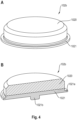
- Fig. 2A-C shows an energy storage cell according to the invention in a view obliquely from above ( Fig. 2A ), in a longitudinal section ( Fig. 2B ) and in a view diagonally from below ( Fig. 2C ).
- the energy storage cell 100 has the shape of a cylindrical round cell.
- the housing of the energy storage cell 100 is formed by a cup-shaped housing part 101 and a cover component.
- the cover component includes a cover plate 102a, which has the shape of a perforated plate, and a connection pole 102b in the center of the cover component.
- the coil-shaped electrode-separator composite 104 which is formed from the wound electrode strips with separator strips in between.
- Fig. 2C the underside of the energy storage cell 100 is shown, which is formed by the housing base 101a.
- the housing base 101a In the housing base 101a there are three weld embossments arranged in a star shape in the form of beads 101d, which act as a recess on the outside and on the inside appear as an elongated elevation.
- the longitudinal edge of the respective current collector sits on the inside of these beads 101d and in the area of these beads the current collector is preferably welded directly to the housing base.
- Aluminum is preferably used as the material for the housing base 101a and the entire cup-shaped housing part 101.
- two security functions are integrated into the housing base 101a.
- there is an opening in the center of the housing base 101a which is closed with a metallic membrane 114.
- pressure equalization is brought about by means of this membrane 114, in which case the membrane is either blown open or blown off by the pressure. In this way, any gas that may have formed inside the cell can escape through the opening in the housing base 101a (primary fuse).
- a further security function is provided in the housing base 101a, which is implemented by three star-shaped grooves 101c.
- These grooves 101c represent weakenings in the structure of the housing base 101a and thus form predetermined breaking points in the event of excess pressure occurring inside the cell (secondary fuse).
- the grooves are located on the inner side of the housing base 101a and are therefore in Fig. 2C shown as dashed lines.
- the grooves 101c can in particular be realized as three scoring lines.
- the star-shaped arrangement of the scoring lines is further developed by a part-circular connection of the scoring lines or the grooves 101c.
- the housing base 101a tears open along the grooves 101c and the part-circular connection of these grooves, so that an outlet opening with a comparatively large cross section is created, through which any gas that may have formed inside the housing can quickly escape.
- Fig. 3A ,B shows an enlarged view of the front areas of the energy storage cell 100 according to the invention
- Fig. 3A Details of the front side with the cover component 102 can be seen.
- the cover component 102 includes the cover plate 102a with a central opening and with the connection pole 102b arranged in the center of the cover plate 102a.
- the connection pole 102b forms the negative pole and the surrounding cover plate 102a forms the positive pole of the energy storage cell 100.
- connection pole 102b Below the connection pole 102b is the contact plate 111, which sits on the free edge strip 106b of the spirally arranged anode current collector of the negative electrode and is welded thereto.
- the contact plate 111 is electrically connected to the connection pole 102b formed from two metallic components, in particular also by welding.
- the cover plate 102a is electrically insulated from the contact plate 111 by an O-ring-shaped insulating disk 112. Furthermore, there is an electrical insulating potting compound 113 in a gap between the connection pole 102b and the cover plate 102a.
- Fig. 3B shows details of the opposite end face of the energy storage cell 100, which is enclosed by the housing base 101a.
- the free edge strip 109b of the cathode current collector is electrically connected, in particular welded, directly to the housing base 101a on this end face of the energy storage cell 100.
- Via the jacket of the cup-shaped housing part 101 there is electrical contact with the metallic cover plate 102a on the opposite end face, so that the positive potential of the cell can also be tapped on the upper end face of the energy storage cell 100.
- the lower end face of the energy storage cell 100 shown shows the safety functions of the cell according to the invention against overpressure.
- the primary fuse is formed by the metallic membrane 114, which closes a central circular opening 101b in the housing base 101a.
- the secondary fuse is formed by the grooves 101c, one of the three star-shaped grooves 101c being visible in section in this illustration.
- the grooves 101c which are located on the inside of the housing base 101a, represent a defined weakening structure of the housing base, so that when there is a relatively high excess pressure that arises inside the cell, these structures can open and gas can escape.
- Fig. 3 illustrated preferred design of the energy storage cell 100 according to the invention allows a reduced number of parts in the upper region of the energy storage cell ( Fig. 3A ), where in this upper area the negative and positive connections of the cell are arranged.
- this design makes it possible to dispense with additional arresters due to the one-piece design of the connection pole 102b.
- the direct contacting of the longitudinal edge of one of the electrode strips on the side of the housing base also serves the particularly compact design of the cell, so that no dead volumes are required for the various functions of the cell.
- Direct contact with the longitudinal edges of the electrode strips also results in improved heat dissipation and a reduction in internal resistance.
- this cell generally allows longer coils to be formed and thus a greater energy density of the resulting energy storage cell.
- the upper end face of the energy storage cell 100 is designed to be as compact as possible in this embodiment. If gases may arise inside the cell and lead to an increase in pressure, these gases are inevitably directed to the lower area of the cell, in which the safety functions for pressure equalization are arranged. Overall, such a cell therefore has a very good level of security.
- connection pole 102b is composed of two metallic components.
- the upper region (pole top part) 1020 is preferably formed by aluminum and the lower region (pole bottom part) 1021 is preferably formed by copper.
- the upper area 1020 has a beveled, circumferential upper edge.
- an externally circumferential welding shoulder 1021a and a central, downwardly projecting pin 1021b are provided in the lower region 1021.
- the pin 1021b expediently engages in a correspondingly provided recess in the center of the contact plate 111 and thus ensures a good fit of the connection pole 102b.
- connection pole 102b can be formed, for example, from a bi-metal strip with aluminum and copper. For example, a blank is punched out of the bi-metal.
- the upper area 1020 with the beveled edge and the lower area 1021 with the central pin 2021b and the circumferential welding shoulder 1021a can be formed by cold forming.
- Copper is particularly suitable for the lower region 1021 of the connection pole 102b, particularly for cases in which the connection pole 102b is intended for contacting an anode current collector via the contact plate 111.
- the anode current collector is also usually made of copper, so this material is also particularly suitable for the connection pole.
- the contact plate 111 is also preferably made of copper.
- the formation of the upper part 1020 of the connection pole 102b from aluminum has the particular advantage that in this case the entire housing of the energy storage cell can be made from aluminum, since the cup-shaped housing part 101 is usually also made from aluminum.
- the cathode current collector which may be electrically contacted with the housing base 101a, is also often made of aluminum. If the energy storage cell 100 is constructed with reversed polarity, it is of course also possible for the metallic materials for the housing and/or the connection pole to be chosen differently.
- Fig. 5A ,B shows the O-ring-shaped insulating disk 112 in a complete view diagonally from above ( Fig. 5A ) and in a sectioned view ( Fig. 5B ).
- the insulating disk 112 has the function of electrically insulating the preferably positively polarized cover plate 102a from the components of the energy storage cell 100 with negative polarity.
- the insulating disk 112 also achieves a liquid-tight and air-tight closure of the housing.
- the insulating disk 112 is made of two different materials.
- the outer region 112a of the insulating disk 112 is preferably made of a particularly strong plastic material, for example PBT (polybutylene terephthalate).
- the inner region 112b is preferably made of a somewhat more flexible and, above all, particularly heat-resistant plastic, for example PET (polyethylene terephthalate).
- PET polyethylene terephthalate
- the outer region 112a thus ensures particular mechanical stability.
- the inner area 112b provides flexibility and is particularly resistant to the hot casting compound 13 when assembling the energy storage cell.
- the inner circumference of the O-ring-shaped insulating disk 112 prefferably has a circumferential thickening, which further supports the stability of the components in the front area of the mounted energy storage cell.
- the insulating disk 112 When assembling the energy storage cell, a temporary sealing of the cell is achieved by inserting the insulating disk 112 in the cover area of the cell until the subsequently introduced potting compound 113 has hardened to completely close the cell. Furthermore, due to its special shape, the insulating disk 112 allows axial support of the coil-shaped electrode-separator composite 104, for example when testing the cell. If the cell is deformed laterally, the shape of the insulating disk 112 also offers space for any deformation of the contact plate 111 that may occur. Finally, the shape of the insulating disk 112 makes it possible to control the volume of the casting compound 113 and the amount of air bubbles that may be trapped during the To reduce potting when assembling the energy storage cell.
- an insulating sealing bead comparable to a silicone bead, can be added. This can also ensure a tight seal.
- the insulating disk 112 particularly in the embodiment illustrated here, offers the various advantages mentioned.
- Fig. 6A ,B shows a preferred embodiment of the contact plate 111, which is intended for contacting the free edge of the current collector of the respective electrode in the upper region of the energy storage cell.
- Fig. 6A shows a top view of the disk-shaped contact plate 111.
- Fig. 6B shows a section through the contact plate 111 in a view from below, i.e. on the side of the contact plate that faces the electrode-separator composite inside the energy storage cell.
- the contact plate 111 Comparable to the beads 101d of the housing base 101a, the contact plate 111 also has three beads 111d arranged in a star shape, which face outwards ( Fig. 6A ) as a depression and inwards ( Fig. 6B ) appear as an elongated elevation.
- the beads 111d can, for example are embossed and have a depth of 0.25 mm, for example.
- the beads 111d are in contact with the respective longitudinal edge of an electrode strip of the electrode-separator composite to be contacted via this.
- the contact plate 111 is preferably welded to the respective longitudinal edge of the electrode strip via the beads 111d.
- connection pole 102b In the center of the contact plate 111 there is a recess 111e.
- the recess 111e serves to accommodate the connection pole 102b by the central pin 1021b of the connection pole 102b engaging in the recess 111e. In this way, the connection pole 102b can be positioned and fixed in a simple manner on the contact plate 111, so that the connection pole 102b can be welded on without any problems.
- further star-shaped narrow recesses 111f are provided, which are located on the inward-facing side of the contact plate 111.
- a total of nine of these depressions 111f are provided as narrow channels arranged in a star shape.
- the channels can have a depth of 0.1 mm, for example.
- the depressions 111f grooves serve to better distribute the electrolyte within the cell.
- the contact plate 111 has an embossed peripheral edge 111g, which is arranged as a desired bend point, in particular with the ridge facing downwards. This target kink makes it easier to assemble the housing of the energy storage cell.
- the contact plate 111 is made of copper sheet, for example a copper sheet with a material thickness of 0.3 mm. Copper is particularly advantageous in cases in which the contact plate is contacted with the longitudinal edge of the anode current collector, which is also preferably made of copper.
- Fig. 7 shows a detailed view of the housing base 101a of the energy storage cell with the star-shaped, inwardly projecting beads 101d, which in particular serve as weld embossments for contacting the coil-shaped electrode-separator composite are trained.
- the star-shaped arrangement with three beads 101d is particularly advantageous for assembling the cell due to its rotational symmetry.
- the central opening 101b in the housing base 101a is covered by a metallic membrane 114 and serves as a primary safety device for the cell in the event of excess pressure.
- the opening 101b is initially used during the production of the cell to fill the cell with electrolyte before the opening 101b is closed with the metallic membrane 114.
- a circumferential recess 1010b is preferably provided, which surrounds the central opening 101b.
- three weakening structures arranged in a star shape are provided in the form of the inwardly open grooves 101c, which are connected to one another by a part-circular connecting line 1010c.
- These weakening structures 101c and 1010c serve as secondary protection against internal overpressure.
- such weakening structures for example scratch lines, can also be attached from the outside.
- One or more labeling fields 1010a can also be provided on the outside of the housing base 101a, which can be used to attach various written information.
- Fig. 8 to 10 illustrate various details in connection with the production of the energy storage cells according to the invention.
- Figs. 8A-C shows exploded views of the various components of an energy storage cell according to the invention.
- the components of the housing with the housing cup 101, the connection pole 102b, the O-ring-shaped insulating disk 112, the cover plate 102 with the central recess into which the connection pole 102b engages, and the casting compound 113 are shown.
- the closure for the energy storage cell is shown in the form of the metallic membrane 114, this closure according to filling the assembled cell with the electrolyte 115 shown schematically here.
- Fig. 8B shows the coil-shaped electrode-separator composite 104 and the contact plate 111 to be attached to it.
- the coil-shaped electrode-separator composite 104 can be produced in a manner known per se by winding the electrode strips and the separators, in particular on a winding machine. To complete the winding form, the outermost winding turn can preferably be bent inwards by, for example, 30° to 45° using a conical pressure piece, so that the winding form is stabilized.
- An adhesive tape 118 ( Fig. 8C ), for example made of polypropylene, which, in addition to the stabilizing function, may also take on an electrically insulating function in the cell.
- the disk-shaped contact plate 111 which is made of copper, for example, can be placed loosely on the upper end face of the coil and fixed with a particularly stable adhesive tape 119 made of, for example, polyimide.
- a tape made of Kapton ® with a thickness of 50 ⁇ m can be used for this.
- the electrode-separator composite 104 with the attached contact plate 111 is then inserted into the cup-shaped housing part 101. After an optional camera-assisted alignment of the beads in the housing base and in the contact plate, the arrangement can be pressed using suitable pressing tools and laser-welded simultaneously or sequentially from above and below to contact the longitudinal edges of the electrode strips with the respective beads.
- the connection pole 102b can then be placed and welded onto the contact plate 111.
- Fig. 9A ,B shows details of the fabrication of the cell lid assembly.
- Out of Fig. 9A shows a detailed view of the welding of the connection pole 102b on the contact plate 111, whereby the laser can attack obliquely or vertically, particularly in the area of the circumferential welding shoulder 1021a of the connection pole 102b.
- Fig. 9B is shown how the insulating disk 112 can then be inserted and pressed to the correct height before the cover plate 102a is placed and welded from an angle, vertically or horizontally to the cup-shaped housing part, not shown here. Now, if necessary, the connection pole 102b can be pressed to the correct height in relation to the cell shoulder formed by the upper side of the cover plate 102a.
- the distance provided for this can be, for example, 1 mm between the top of the connection pole 102b and the top of the cover plate 102a.
- the gap between the cover plate 102a and the connection pole 102b is filled with a casting compound 113 in order to seal this part of the energy storage cell in an airtight and liquid-tight manner.
- the energy storage cell can then be placed in an oven to set the casting compound 113 and to bake out the residual moisture of the coil-shaped electrode-separator composite.
- Fig. 10 illustrates the final filling with electrolyte 115, which is filled from the underside of the energy storage cell 100 (at the top in this illustration) through the opening 101b in the housing base 101a.
- the metallic membrane 114 is applied as a closure to the opening in the housing base 101a or as a closure to the central opening 101b. For this purpose, for example, you can work with a vertical laser beam.
- Fig. 11 illustrates an alternative way to assemble the lid assembly.
- Fig. 11A shows the contact plate 111 with the connecting pole 102b attached to it in a sectioned view obliquely from below.
- Fig. 11B shows the upper end area of the cell in a longitudinal section.
- connection pole 102b is welded onto the contact plate 111 in advance. Friction welding or friction stir welding can be used for this.
- the star-shaped beads 111d of the contact plate 111 can be shortened if necessary, since they are covered by the connection pole 102b during the subsequent welding of the electrode-separator composite. Overall, there is therefore slightly less welding surface the contacting of the longitudinal edge of the respective electrode strip with the contact plate 111 is available. However, this design can offer advantages for assembly.
- connection pole 102b Since it may be easier to attach the connection pole 102b directly to the contact plate 111 outside the housing cup assembly, a central recess in the contact plate and a corresponding pin on the connection pole 102b can be dispensed with if necessary.
- connection pole 102b which is already welded directly onto the contact plate 111, does not differ in principle from the previously described manufacturing process for the energy storage cell 100.
- the invention relates to an energy storage element with an electrode-separator composite and a metallic housing cup.
- the electrodes of the electrode-separator composite are electrically contacted via one of their longitudinal edges, preferably directly on one end face of the energy storage element with a contact plate and on the other end face of the energy storage element with the housing base.
- This energy storage element is characterized by the primary fuse explained in detail and the secondary fuse in the housing base.
- the invention comprises an energy storage element with an electrode-separator composite and a metallic housing cup.
- the electrodes of the electrode-separator composite are electrically contacted via one of their longitudinal edges, preferably directly on one end face of the energy storage element with a contact plate and on the other end face of the energy storage element with the housing base.
- This energy storage element is further characterized by the fact that a cover component with a metallic cover plate and a connection pole are provided in a compact design.
- the connection pole preferably forms the negative pole and the cover plate forms the negative pole positive pole of the element.
- the connection pole is preferably formed by two metallic components that are connected to one another as bi-metal. This connection pole is preferably in accordance with the Fig. 4 explained embodiment realized.
- the invention comprises an energy storage element with an electrode-separator composite and a metallic housing cup.
- the electrodes of the electrode-separator composite are electrically contacted via one of their longitudinal edges, preferably directly on one end face of the energy storage element with a contact plate and on the other end face of the energy storage element with the housing base.
- This energy storage element is further characterized in that an O-ring-shaped insulating disk is provided to seal the connection pole from the other components of the element with opposite polarity.
- This insulating disk is preferably formed from two plastic components.
- the insulating pane is characterized by the features according to Fig. 5 explained configuration.
- the invention comprises an energy storage element with an electrode-separator composite and a metallic housing cup.
- the electrodes of the electrode-separator composite are electrically contacted via one of their longitudinal edges, preferably directly on one end face of the energy storage element with a contact plate and on the other end face of the energy storage element with the housing base.
- This energy storage element is further characterized by the fact that the contact plate has no opening. Additionally or alternatively, in a preferred embodiment, the contact plate has a central recess which serves to position a connection pole to be attached to this contact plate.
- the contact plate is equipped with at least one trough-shaped recess which points into the interior of the energy storage element equipped therewith and which is intended for optimized electrolyte distribution within the element.
- This contact plate is preferably characterized by the features that are based on the Fig. 6 were explained in more detail.
- the invention comprises an energy storage element with an electrode-separator composite and a metallic housing cup.
- the electrodes of the electrode-separator composite are preferably directly over one of their longitudinal edges electrically contacted on one end face of the energy storage element with a contact plate and on the other end face of the energy storage element with the housing base.
- This energy storage element is further characterized in that a casting compound is provided to seal the outwardly guided polarities of the element from one another, which is introduced into a gap during assembly of the cell, which is between a connection pole of the element and the inner edge of a cover plate a central opening. The connection pole engages in the central opening in the cover plate.
- connection pole forms one polarity and the surrounding cover plate forms the opposite polarity of the element.
- the element is characterized by the Fig. 3 and Fig. 9 explained features and, if necessary alternatively, by means of Fig. 11 explained features.
- Such a potting for sealing and electrically insulating an energy storage element is particularly advantageous in combination with a compact design in the area of the cover assembly of the element.
- a contact plate that has no openings is particularly advantageous, for example a contact plate according to in Fig. 3 shown embodiment with a central recess or according to in Fig. 11 embodiment shown without a central recess.
Landscapes
- Chemical & Material Sciences (AREA)
- Chemical Kinetics & Catalysis (AREA)
- Electrochemistry (AREA)
- General Chemical & Material Sciences (AREA)
- Engineering & Computer Science (AREA)
- Manufacturing & Machinery (AREA)
- Inorganic Chemistry (AREA)
- Materials Engineering (AREA)
- Secondary Cells (AREA)
- Connection Of Batteries Or Terminals (AREA)
- Sealing Battery Cases Or Jackets (AREA)
- Electric Double-Layer Capacitors Or The Like (AREA)
- Gas Exhaust Devices For Batteries (AREA)
Priority Applications (7)
| Application Number | Priority Date | Filing Date | Title |
|---|---|---|---|
| EP22169512.5A EP4266437A1 (fr) | 2022-04-22 | 2022-04-22 | Élément d'accumulateur d'énergie et procédé de fabrication |
| EP22182808.0A EP4266438A1 (fr) | 2022-04-22 | 2022-07-04 | Élément d'accumulateur d'énergie et procédé de fabrication |
| US18/301,333 US20230344048A1 (en) | 2022-04-22 | 2023-04-17 | Energy storage element and production method |
| PCT/EP2023/060340 WO2023203155A1 (fr) | 2022-04-22 | 2023-04-20 | Élément de stockage d'énergie et procédé de production |
| CN202310435341.0A CN116936948A (zh) | 2022-04-22 | 2023-04-21 | 蓄能器元件以及制造方法 |
| KR1020230052707A KR20230150757A (ko) | 2022-04-22 | 2023-04-21 | 에너지 저장 요소 및 제조 방법 |
| JP2023069727A JP2023160803A (ja) | 2022-04-22 | 2023-04-21 | エネルギー貯蔵要素及び生産方法 |
Applications Claiming Priority (1)
| Application Number | Priority Date | Filing Date | Title |
|---|---|---|---|
| EP22169512.5A EP4266437A1 (fr) | 2022-04-22 | 2022-04-22 | Élément d'accumulateur d'énergie et procédé de fabrication |
Publications (1)
| Publication Number | Publication Date |
|---|---|
| EP4266437A1 true EP4266437A1 (fr) | 2023-10-25 |
Family
ID=81346476
Family Applications (2)
| Application Number | Title | Priority Date | Filing Date |
|---|---|---|---|
| EP22169512.5A Pending EP4266437A1 (fr) | 2022-04-22 | 2022-04-22 | Élément d'accumulateur d'énergie et procédé de fabrication |
| EP22182808.0A Pending EP4266438A1 (fr) | 2022-04-22 | 2022-07-04 | Élément d'accumulateur d'énergie et procédé de fabrication |
Family Applications After (1)
| Application Number | Title | Priority Date | Filing Date |
|---|---|---|---|
| EP22182808.0A Pending EP4266438A1 (fr) | 2022-04-22 | 2022-07-04 | Élément d'accumulateur d'énergie et procédé de fabrication |
Country Status (6)
| Country | Link |
|---|---|
| US (1) | US20230344048A1 (fr) |
| EP (2) | EP4266437A1 (fr) |
| JP (1) | JP2023160803A (fr) |
| KR (1) | KR20230150757A (fr) |
| CN (1) | CN116936948A (fr) |
| WO (1) | WO2023203155A1 (fr) |
Citations (4)
| Publication number | Priority date | Publication date | Assignee | Title |
|---|---|---|---|---|
| US20060019150A1 (en) | 2004-07-23 | 2006-01-26 | Saft | Safety device for a sealed cell |
| WO2017215900A1 (fr) | 2016-06-16 | 2017-12-21 | Varta Microbattery Gmbh | Cellule électrochimique à résistance intérieure optimisée |
| WO2021239492A1 (fr) * | 2020-05-29 | 2021-12-02 | Varta Microbattery Gmbh | Cellule au lithium-ion à haute densité d'énergie |
| EP3965196A1 (fr) * | 2020-09-07 | 2022-03-09 | VARTA Microbattery GmbH | Cellule d'accumulation d'énergie |
Family Cites Families (1)
| Publication number | Priority date | Publication date | Assignee | Title |
|---|---|---|---|---|
| DE102017216871A1 (de) * | 2017-09-25 | 2019-03-28 | Robert Bosch Gmbh | Deckel für eine Batteriezelle |
-
2022
- 2022-04-22 EP EP22169512.5A patent/EP4266437A1/fr active Pending
- 2022-07-04 EP EP22182808.0A patent/EP4266438A1/fr active Pending
-
2023
- 2023-04-17 US US18/301,333 patent/US20230344048A1/en active Pending
- 2023-04-20 WO PCT/EP2023/060340 patent/WO2023203155A1/fr unknown
- 2023-04-21 JP JP2023069727A patent/JP2023160803A/ja active Pending
- 2023-04-21 KR KR1020230052707A patent/KR20230150757A/ko unknown
- 2023-04-21 CN CN202310435341.0A patent/CN116936948A/zh active Pending
Patent Citations (4)
| Publication number | Priority date | Publication date | Assignee | Title |
|---|---|---|---|---|
| US20060019150A1 (en) | 2004-07-23 | 2006-01-26 | Saft | Safety device for a sealed cell |
| WO2017215900A1 (fr) | 2016-06-16 | 2017-12-21 | Varta Microbattery Gmbh | Cellule électrochimique à résistance intérieure optimisée |
| WO2021239492A1 (fr) * | 2020-05-29 | 2021-12-02 | Varta Microbattery Gmbh | Cellule au lithium-ion à haute densité d'énergie |
| EP3965196A1 (fr) * | 2020-09-07 | 2022-03-09 | VARTA Microbattery GmbH | Cellule d'accumulation d'énergie |
Also Published As
| Publication number | Publication date |
|---|---|
| EP4266438A1 (fr) | 2023-10-25 |
| US20230344048A1 (en) | 2023-10-26 |
| CN116936948A (zh) | 2023-10-24 |
| KR20230150757A (ko) | 2023-10-31 |
| JP2023160803A (ja) | 2023-11-02 |
| WO2023203155A1 (fr) | 2023-10-26 |
Similar Documents
| Publication | Publication Date | Title |
|---|---|---|
| WO2022023321A1 (fr) | Cellule de stockage d'énergie et procédé de production | |
| EP3916827A1 (fr) | Élément lithium-ion à haute densité énergétique | |
| WO2022184403A1 (fr) | Procédé de production d'élément de stockage d'énergie électrochimique | |
| WO2022034156A1 (fr) | Cellule de stockage d'énergie et procédé de production | |
| WO2022048969A1 (fr) | Cellule d'accumulateur d'énergie | |
| EP3916868A1 (fr) | Élément d'accumulateur d'énergie et procédé de fabrication | |
| EP3745490B1 (fr) | Procédé de fabrication d'une batterie et batterie fabriquée selon ledit procédé | |
| EP4158712B1 (fr) | Élément lithium-ion à haute densité énergétique | |
| WO2022058342A1 (fr) | Élément lithium-ion à haute densité d'énergie spécifique | |
| EP4143903A1 (fr) | Pile électrochimique au lithium-ion secondaire | |
| EP4266437A1 (fr) | Élément d'accumulateur d'énergie et procédé de fabrication | |
| EP4135088A1 (fr) | Élément accumulateur d'énergie, composite constitué d'éléments accumulateurs d'énergie et procédé de fabrication | |
| EP4333138A1 (fr) | Élément d'accumulation d'énergie et procédé de fabrication d'un tel élément d'accumulation d'énergie | |
| WO2023016769A1 (fr) | Élément de stockage d'énergie, ensemble d'éléments de stockage d'énergie et processus de production | |
| EP4197051A1 (fr) | Cellule de stockage d'énergie et procédé de production | |
| EP4187688A1 (fr) | Cellule d'accumulateur d'énergie, composite de cellules d'accumulateur d'énergie et procédé de fabrication | |
| EP4258397A1 (fr) | Élément d'accumulation d'énergie pourvu de boîtier cylindrique et procédé de fabrication | |
| WO2023057112A1 (fr) | Élément de stockage d'énergie et son procédé de production | |
| EP4152434A1 (fr) | Élément accumulateur d'énergie | |
| EP4336644A1 (fr) | Élément de stockage d'énergie et batterie | |
| WO2023194591A1 (fr) | Cellule de stockage d'énergie comprenant un boîtier cylindrique et procédé de fabrication | |
| EP4270614A1 (fr) | Élément d'accumulateur d'énergie | |
| EP4170812A1 (fr) | Cellule lithium-ion | |
| DE102022113906A1 (de) | Energiespeicherzelle mit zylindrischem Gehäuse und Verfahren zur Herstellung | |
| EP4164049A1 (fr) | Élément d'accumulateur d'énergie et procédé de fabrication |
Legal Events
| Date | Code | Title | Description |
|---|---|---|---|
| STAA | Information on the status of an ep patent application or granted ep patent |
Free format text: STATUS: THE APPLICATION HAS BEEN PUBLISHED |
|
| PUAI | Public reference made under article 153(3) epc to a published international application that has entered the european phase |
Free format text: ORIGINAL CODE: 0009012 |
|
| AK | Designated contracting states |
Kind code of ref document: A1 Designated state(s): AL AT BE BG CH CY CZ DE DK EE ES FI FR GB GR HR HU IE IS IT LI LT LU LV MC MK MT NL NO PL PT RO RS SE SI SK SM TR |
|
| STAA | Information on the status of an ep patent application or granted ep patent |
Free format text: STATUS: REQUEST FOR EXAMINATION WAS MADE |
|
| 17P | Request for examination filed |
Effective date: 20231223 |
|
| RBV | Designated contracting states (corrected) |
Designated state(s): AL AT BE BG CH CY CZ DE DK EE ES FI FR GB GR HR HU IE IS IT LI LT LU LV MC MK MT NL NO PL PT RO RS SE SI SK SM TR |