EP4187688A1 - Cellule d'accumulateur d'énergie, composite de cellules d'accumulateur d'énergie et procédé de fabrication - Google Patents
Cellule d'accumulateur d'énergie, composite de cellules d'accumulateur d'énergie et procédé de fabrication Download PDFInfo
- Publication number
- EP4187688A1 EP4187688A1 EP21210297.4A EP21210297A EP4187688A1 EP 4187688 A1 EP4187688 A1 EP 4187688A1 EP 21210297 A EP21210297 A EP 21210297A EP 4187688 A1 EP4187688 A1 EP 4187688A1
- Authority
- EP
- European Patent Office
- Prior art keywords
- energy storage
- housing cup
- edge
- current collector
- housing
- Prior art date
- Legal status (The legal status is an assumption and is not a legal conclusion. Google has not performed a legal analysis and makes no representation as to the accuracy of the status listed.)
- Withdrawn
Links
- 238000004146 energy storage Methods 0.000 title claims abstract description 74
- 239000002131 composite material Substances 0.000 title claims abstract description 29
- 238000004519 manufacturing process Methods 0.000 title claims abstract description 7
- 210000000352 storage cell Anatomy 0.000 claims abstract description 71
- 210000004027 cell Anatomy 0.000 claims abstract description 68
- 238000004804 winding Methods 0.000 claims abstract description 21
- 229910052751 metal Inorganic materials 0.000 claims abstract description 13
- 239000002184 metal Substances 0.000 claims abstract description 13
- 239000012777 electrically insulating material Substances 0.000 claims abstract description 4
- 238000003466 welding Methods 0.000 claims description 23
- 239000004020 conductor Substances 0.000 claims description 20
- 239000000463 material Substances 0.000 claims description 15
- 239000012528 membrane Substances 0.000 claims description 11
- 239000007772 electrode material Substances 0.000 claims description 8
- 238000007373 indentation Methods 0.000 claims description 8
- -1 polytetrafluoroethylene Polymers 0.000 claims description 7
- 229920002530 polyetherether ketone Polymers 0.000 claims description 6
- 229920001721 polyimide Polymers 0.000 claims description 6
- 239000007773 negative electrode material Substances 0.000 claims description 5
- 239000004033 plastic Substances 0.000 claims description 5
- 229920003023 plastic Polymers 0.000 claims description 5
- 239000007774 positive electrode material Substances 0.000 claims description 4
- 239000004696 Poly ether ether ketone Substances 0.000 claims description 3
- 239000004642 Polyimide Substances 0.000 claims description 3
- 239000004734 Polyphenylene sulfide Substances 0.000 claims description 3
- 238000002844 melting Methods 0.000 claims description 3
- 230000008018 melting Effects 0.000 claims description 3
- 229920000069 polyphenylene sulfide Polymers 0.000 claims description 3
- 229920001343 polytetrafluoroethylene Polymers 0.000 claims description 3
- 239000004810 polytetrafluoroethylene Substances 0.000 claims description 3
- 238000005520 cutting process Methods 0.000 claims 1
- 229910001416 lithium ion Inorganic materials 0.000 description 16
- PXHVJJICTQNCMI-UHFFFAOYSA-N Nickel Chemical compound [Ni] PXHVJJICTQNCMI-UHFFFAOYSA-N 0.000 description 14
- 229910052782 aluminium Inorganic materials 0.000 description 12
- XAGFODPZIPBFFR-UHFFFAOYSA-N aluminium Chemical compound [Al] XAGFODPZIPBFFR-UHFFFAOYSA-N 0.000 description 12
- 210000004379 membrane Anatomy 0.000 description 11
- 229910000838 Al alloy Inorganic materials 0.000 description 10
- RYGMFSIKBFXOCR-UHFFFAOYSA-N Copper Chemical compound [Cu] RYGMFSIKBFXOCR-UHFFFAOYSA-N 0.000 description 10
- 229910052744 lithium Inorganic materials 0.000 description 10
- WHXSMMKQMYFTQS-UHFFFAOYSA-N Lithium Chemical compound [Li] WHXSMMKQMYFTQS-UHFFFAOYSA-N 0.000 description 9
- OKTJSMMVPCPJKN-UHFFFAOYSA-N Carbon Chemical compound [C] OKTJSMMVPCPJKN-UHFFFAOYSA-N 0.000 description 8
- 239000010949 copper Substances 0.000 description 8
- 239000011149 active material Substances 0.000 description 7
- 229910045601 alloy Inorganic materials 0.000 description 6
- 239000000956 alloy Substances 0.000 description 6
- 229910052802 copper Inorganic materials 0.000 description 6
- 239000003792 electrolyte Substances 0.000 description 6
- 229910052759 nickel Inorganic materials 0.000 description 6
- 239000002245 particle Substances 0.000 description 6
- 229910052799 carbon Inorganic materials 0.000 description 5
- 239000011883 electrode binding agent Substances 0.000 description 5
- 239000002033 PVDF binder Substances 0.000 description 4
- 239000011324 bead Substances 0.000 description 4
- 238000005452 bending Methods 0.000 description 4
- 239000011888 foil Substances 0.000 description 4
- 238000005259 measurement Methods 0.000 description 4
- 238000000034 method Methods 0.000 description 4
- 239000000203 mixture Substances 0.000 description 4
- 229920002981 polyvinylidene fluoride Polymers 0.000 description 4
- 229910052710 silicon Inorganic materials 0.000 description 4
- 239000010703 silicon Substances 0.000 description 4
- 229910000789 Aluminium-silicon alloy Inorganic materials 0.000 description 3
- 229910000881 Cu alloy Inorganic materials 0.000 description 3
- 229910000990 Ni alloy Inorganic materials 0.000 description 3
- RTAQQCXQSZGOHL-UHFFFAOYSA-N Titanium Chemical compound [Ti] RTAQQCXQSZGOHL-UHFFFAOYSA-N 0.000 description 3
- 239000000654 additive Substances 0.000 description 3
- 150000001875 compounds Chemical class 0.000 description 3
- 150000002500 ions Chemical class 0.000 description 3
- 229910003002 lithium salt Inorganic materials 0.000 description 3
- 159000000002 lithium salts Chemical class 0.000 description 3
- 229920002134 Carboxymethyl cellulose Polymers 0.000 description 2
- 229910003336 CuNi Inorganic materials 0.000 description 2
- 229910001030 Iron–nickel alloy Inorganic materials 0.000 description 2
- 229910012851 LiCoO 2 Inorganic materials 0.000 description 2
- 229910010707 LiFePO 4 Inorganic materials 0.000 description 2
- 229910013870 LiPF 6 Inorganic materials 0.000 description 2
- HBBGRARXTFLTSG-UHFFFAOYSA-N Lithium ion Chemical compound [Li+] HBBGRARXTFLTSG-UHFFFAOYSA-N 0.000 description 2
- 229910003322 NiCu Inorganic materials 0.000 description 2
- XUIMIQQOPSSXEZ-UHFFFAOYSA-N Silicon Chemical compound [Si] XUIMIQQOPSSXEZ-UHFFFAOYSA-N 0.000 description 2
- 229910000831 Steel Inorganic materials 0.000 description 2
- ATJFFYVFTNAWJD-UHFFFAOYSA-N Tin Chemical compound [Sn] ATJFFYVFTNAWJD-UHFFFAOYSA-N 0.000 description 2
- 229910052787 antimony Inorganic materials 0.000 description 2
- WATWJIUSRGPENY-UHFFFAOYSA-N antimony atom Chemical compound [Sb] WATWJIUSRGPENY-UHFFFAOYSA-N 0.000 description 2
- 239000001768 carboxy methyl cellulose Substances 0.000 description 2
- 235000010948 carboxy methyl cellulose Nutrition 0.000 description 2
- 239000008112 carboxymethyl-cellulose Substances 0.000 description 2
- VNNRSPGTAMTISX-UHFFFAOYSA-N chromium nickel Chemical compound [Cr].[Ni] VNNRSPGTAMTISX-UHFFFAOYSA-N 0.000 description 2
- 230000007797 corrosion Effects 0.000 description 2
- 238000005260 corrosion Methods 0.000 description 2
- 238000012983 electrochemical energy storage Methods 0.000 description 2
- 239000010439 graphite Substances 0.000 description 2
- 229910002804 graphite Inorganic materials 0.000 description 2
- 229910003473 lithium bis(trifluoromethanesulfonyl)imide Inorganic materials 0.000 description 2
- VDVLPSWVDYJFRW-UHFFFAOYSA-N lithium;bis(fluorosulfonyl)azanide Chemical compound [Li+].FS(=O)(=O)[N-]S(F)(=O)=O VDVLPSWVDYJFRW-UHFFFAOYSA-N 0.000 description 2
- QSZMZKBZAYQGRS-UHFFFAOYSA-N lithium;bis(trifluoromethylsulfonyl)azanide Chemical compound [Li+].FC(F)(F)S(=O)(=O)[N-]S(=O)(=O)C(F)(F)F QSZMZKBZAYQGRS-UHFFFAOYSA-N 0.000 description 2
- 239000011572 manganese Substances 0.000 description 2
- 239000011159 matrix material Substances 0.000 description 2
- 150000002739 metals Chemical class 0.000 description 2
- 229910001120 nichrome Inorganic materials 0.000 description 2
- 239000003960 organic solvent Substances 0.000 description 2
- 239000002985 plastic film Substances 0.000 description 2
- 229920006255 plastic film Polymers 0.000 description 2
- 239000010935 stainless steel Substances 0.000 description 2
- 229910001220 stainless steel Inorganic materials 0.000 description 2
- 239000010959 steel Substances 0.000 description 2
- 239000000126 substance Substances 0.000 description 2
- 229910052718 tin Inorganic materials 0.000 description 2
- 239000010936 titanium Substances 0.000 description 2
- BTBUEUYNUDRHOZ-UHFFFAOYSA-N Borate Chemical compound [O-]B([O-])[O-] BTBUEUYNUDRHOZ-UHFFFAOYSA-N 0.000 description 1
- 229920000049 Carbon (fiber) Polymers 0.000 description 1
- 241000219504 Caryophyllales Species 0.000 description 1
- 229910013063 LiBF 4 Inorganic materials 0.000 description 1
- 229910015643 LiMn 2 O 4 Inorganic materials 0.000 description 1
- 229910013716 LiNi Inorganic materials 0.000 description 1
- VYPSYNLAJGMNEJ-UHFFFAOYSA-N Silicium dioxide Chemical compound O=[Si]=O VYPSYNLAJGMNEJ-UHFFFAOYSA-N 0.000 description 1
- 206010040954 Skin wrinkling Diseases 0.000 description 1
- 229910001069 Ti alloy Inorganic materials 0.000 description 1
- SFKQQYOXXWIJSA-UHFFFAOYSA-N [Li+].[O--].[O--].[O--].[O--].[O--].[Al+3].[Mn++].[Co++].[Ni++] Chemical compound [Li+].[O--].[O--].[O--].[O--].[O--].[Al+3].[Mn++].[Co++].[Ni++] SFKQQYOXXWIJSA-UHFFFAOYSA-N 0.000 description 1
- KLARSDUHONHPRF-UHFFFAOYSA-N [Li].[Mn] Chemical compound [Li].[Mn] KLARSDUHONHPRF-UHFFFAOYSA-N 0.000 description 1
- 239000002253 acid Substances 0.000 description 1
- 230000000996 additive effect Effects 0.000 description 1
- 238000004026 adhesive bonding Methods 0.000 description 1
- 239000002390 adhesive tape Substances 0.000 description 1
- 239000004411 aluminium Substances 0.000 description 1
- NDPGDHBNXZOBJS-UHFFFAOYSA-N aluminum lithium cobalt(2+) nickel(2+) oxygen(2-) Chemical compound [Li+].[O--].[O--].[O--].[O--].[Al+3].[Co++].[Ni++] NDPGDHBNXZOBJS-UHFFFAOYSA-N 0.000 description 1
- 239000011230 binding agent Substances 0.000 description 1
- OJIJEKBXJYRIBZ-UHFFFAOYSA-N cadmium nickel Chemical group [Ni].[Cd] OJIJEKBXJYRIBZ-UHFFFAOYSA-N 0.000 description 1
- 239000004917 carbon fiber Substances 0.000 description 1
- 239000002041 carbon nanotube Substances 0.000 description 1
- 229910021393 carbon nanotube Inorganic materials 0.000 description 1
- 239000002388 carbon-based active material Substances 0.000 description 1
- 239000003575 carbonaceous material Substances 0.000 description 1
- BVKZGUZCCUSVTD-UHFFFAOYSA-N carbonic acid Chemical compound OC(O)=O BVKZGUZCCUSVTD-UHFFFAOYSA-N 0.000 description 1
- 238000006243 chemical reaction Methods 0.000 description 1
- 150000004292 cyclic ethers Chemical class 0.000 description 1
- 230000001419 dependent effect Effects 0.000 description 1
- 238000007599 discharging Methods 0.000 description 1
- 230000000694 effects Effects 0.000 description 1
- 239000011262 electrochemically active material Substances 0.000 description 1
- 238000003411 electrode reaction Methods 0.000 description 1
- 150000002148 esters Chemical class 0.000 description 1
- 150000002170 ethers Chemical class 0.000 description 1
- 239000012212 insulator Substances 0.000 description 1
- 238000009830 intercalation Methods 0.000 description 1
- 238000003475 lamination Methods 0.000 description 1
- 229910000625 lithium cobalt oxide Inorganic materials 0.000 description 1
- GELKBWJHTRAYNV-UHFFFAOYSA-K lithium iron phosphate Chemical compound [Li+].[Fe+2].[O-]P([O-])([O-])=O GELKBWJHTRAYNV-UHFFFAOYSA-K 0.000 description 1
- 229910021450 lithium metal oxide Inorganic materials 0.000 description 1
- 229910001496 lithium tetrafluoroborate Inorganic materials 0.000 description 1
- CJYZTOPVWURGAI-UHFFFAOYSA-N lithium;manganese;manganese(3+);oxygen(2-) Chemical compound [Li+].[O-2].[O-2].[O-2].[O-2].[Mn].[Mn+3] CJYZTOPVWURGAI-UHFFFAOYSA-N 0.000 description 1
- VGYDTVNNDKLMHX-UHFFFAOYSA-N lithium;manganese;nickel;oxocobalt Chemical compound [Li].[Mn].[Ni].[Co]=O VGYDTVNNDKLMHX-UHFFFAOYSA-N 0.000 description 1
- BFZPBUKRYWOWDV-UHFFFAOYSA-N lithium;oxido(oxo)cobalt Chemical compound [Li+].[O-][Co]=O BFZPBUKRYWOWDV-UHFFFAOYSA-N 0.000 description 1
- 229910052987 metal hydride Inorganic materials 0.000 description 1
- 239000006262 metallic foam Substances 0.000 description 1
- 229910001317 nickel manganese cobalt oxide (NMC) Inorganic materials 0.000 description 1
- 150000002825 nitriles Chemical class 0.000 description 1
- 239000004745 nonwoven fabric Substances 0.000 description 1
- 150000005677 organic carbonates Chemical class 0.000 description 1
- 238000013021 overheating Methods 0.000 description 1
- 230000003647 oxidation Effects 0.000 description 1
- 238000007254 oxidation reaction Methods 0.000 description 1
- 150000003013 phosphoric acid derivatives Chemical class 0.000 description 1
- 229920000058 polyacrylate Polymers 0.000 description 1
- 229920000642 polymer Polymers 0.000 description 1
- 239000000843 powder Substances 0.000 description 1
- 238000006479 redox reaction Methods 0.000 description 1
- 230000001105 regulatory effect Effects 0.000 description 1
- 230000000284 resting effect Effects 0.000 description 1
- 230000002441 reversible effect Effects 0.000 description 1
- 238000007789 sealing Methods 0.000 description 1
- 239000003566 sealing material Substances 0.000 description 1
- LIVNPJMFVYWSIS-UHFFFAOYSA-N silicon monoxide Chemical compound [Si-]#[O+] LIVNPJMFVYWSIS-UHFFFAOYSA-N 0.000 description 1
- 229910052814 silicon oxide Inorganic materials 0.000 description 1
- 239000004071 soot Substances 0.000 description 1
- 229910052596 spinel Inorganic materials 0.000 description 1
- 239000011029 spinel Substances 0.000 description 1
- 239000007858 starting material Substances 0.000 description 1
- 239000011232 storage material Substances 0.000 description 1
- 229920003048 styrene butadiene rubber Polymers 0.000 description 1
- 239000000758 substrate Substances 0.000 description 1
- 230000008646 thermal stress Effects 0.000 description 1
- 229910052719 titanium Inorganic materials 0.000 description 1
Images


Classifications
-
- H—ELECTRICITY
- H01—ELECTRIC ELEMENTS
- H01M—PROCESSES OR MEANS, e.g. BATTERIES, FOR THE DIRECT CONVERSION OF CHEMICAL ENERGY INTO ELECTRICAL ENERGY
- H01M50/00—Constructional details or processes of manufacture of the non-active parts of electrochemical cells other than fuel cells, e.g. hybrid cells
- H01M50/10—Primary casings, jackets or wrappings of a single cell or a single battery
- H01M50/102—Primary casings, jackets or wrappings of a single cell or a single battery characterised by their shape or physical structure
- H01M50/107—Primary casings, jackets or wrappings of a single cell or a single battery characterised by their shape or physical structure having curved cross-section, e.g. round or elliptic
-
- H—ELECTRICITY
- H01—ELECTRIC ELEMENTS
- H01M—PROCESSES OR MEANS, e.g. BATTERIES, FOR THE DIRECT CONVERSION OF CHEMICAL ENERGY INTO ELECTRICAL ENERGY
- H01M50/00—Constructional details or processes of manufacture of the non-active parts of electrochemical cells other than fuel cells, e.g. hybrid cells
- H01M50/10—Primary casings, jackets or wrappings of a single cell or a single battery
- H01M50/147—Lids or covers
- H01M50/166—Lids or covers characterised by the methods of assembling casings with lids
- H01M50/167—Lids or covers characterised by the methods of assembling casings with lids by crimping
-
- H—ELECTRICITY
- H01—ELECTRIC ELEMENTS
- H01M—PROCESSES OR MEANS, e.g. BATTERIES, FOR THE DIRECT CONVERSION OF CHEMICAL ENERGY INTO ELECTRICAL ENERGY
- H01M50/00—Constructional details or processes of manufacture of the non-active parts of electrochemical cells other than fuel cells, e.g. hybrid cells
- H01M50/50—Current conducting connections for cells or batteries
- H01M50/543—Terminals
- H01M50/552—Terminals characterised by their shape
- H01M50/559—Terminals adapted for cells having curved cross-section, e.g. round, elliptic or button cells
Definitions
- the invention described below relates to an energy storage cell, an assembly of energy storage cells and a production method.
- Electrochemical energy storage elements are capable of converting stored chemical energy into electrical energy through a redox reaction.
- the simplest form of electrochemical energy storage element is the electrochemical cell. It comprises a positive and a negative electrode separated from each other by a separator. During a discharge, electrons are released at the negative electrode as a result of an oxidation process. This results in an electron stream that can be tapped off by an external electrical consumer for which the electrochemical cell serves as an energy supplier. At the same time, an ion current corresponding to the electrode reaction occurs within the cell. This flow of ions traverses the separator and is made possible by an ion-conducting electrolyte.
- the discharge is reversible, i.e. if there is the possibility of reversing the conversion of chemical energy into electrical energy during the discharge and charging the cell again, this is referred to as a secondary cell.
- Secondary lithium-ion cells are used today as energy storage elements for many applications, since they can provide high currents and are characterized by a comparatively high energy density. They are based on the use of lithium, which can migrate back and forth between the electrodes of the cell in the form of ions.
- the negative electrode and the positive electrode of a lithium-ion cell are usually formed by what are known as composite electrodes, which also include electrochemically inactive components in addition to electrochemically active components.
- electrochemically active components for secondary lithium-ion cells.
- carbon-based particles such as graphitic carbon are used for the negative electrode.
- positive electrode active materials For example, lithium cobalt oxide (LiCoO 2 ), lithium manganese oxide (LiMn 2 O 4 ), lithium iron phosphate (LiFePO 4 ) or derivatives thereof can be used.
- the electrochemically active materials are usually contained in the electrodes in particle form.
- the composite electrodes generally include a flat and/or strip-shaped current collector, for example a metallic foil, which serves as a carrier for the respective active material.
- the current collector for the negative electrode can be formed of, for example, copper or nickel
- the current collector for the positive electrode can be formed of, for example, aluminum.
- the electrodes can comprise an electrode binder (e.g. polyvinylidene fluoride (PVDF) or another polymer, for example carboxymethyl cellulose), conductivity-improving additives and other additives as electrochemically inactive components.
- PVDF polyvinylidene fluoride
- the electrode binder ensures the mechanical stability of the electrodes and often also the adhesion of the active material to the current collectors.
- lithium-ion cells usually include solutions of lithium salts such as lithium hexafluorophosphate (LiPF 6 ) in organic solvents (e.g. ethers and esters of carbonic acid).
- lithium salts such as lithium hexafluorophosphate (LiPF 6 ) in organic solvents (e.g. ethers and esters of carbonic acid).
- the composite electrodes are combined with one or more separators to form a composite body.
- the electrodes and separators are usually connected to one another under pressure, optionally also by lamination or by gluing.
- the basic functionality of the cell can then be established by impregnating the composite with the electrolyte.
- the composite body is formed in the form of a coil or fabricated into a coil. It usually includes the sequence positive electrode / separator / negative electrode. Composite bodies are often produced as so-called bicells with the possible sequences negative electrode/separator/positive electrode/separator/negative electrode or positive electrode/separator/negative electrode/separator/positive electrode.
- lithium-ion cells For applications in the automotive sector, for e-bikes or for other applications with high energy requirements such as in tools, lithium-ion cells with the highest possible energy density are required, which are also able to withstand high currents when charging and discharging to become.
- Cells for the applications mentioned are often designed as cylindrical round cells, for example with the form factor 21 ⁇ 70 (diameter times height in mm). Cells of this type always comprise a composite body in the form of a coil. Modern lithium-ion cells of this form factor can already achieve an energy density of up to 270 Wh/kg. However, this energy density is only seen as an intermediate step. The market is already demanding cells with even higher energy densities.
- Cylindrical round cells are described in which the electrode-separator composite and its electrodes are designed in the form of a strip and are present in the form of a coil.
- the electrodes each have current collectors loaded with electrode material.
- Oppositely polarized electrodes are arranged offset to one another within the electrode-separator combination, so that longitudinal edges of the current collectors of the positive electrodes emerge from the winding on one side and longitudinal edges of the current collectors of the negative electrodes on another side.
- the cell has a contact plate which is seated on an end face of the winding and is connected to a longitudinal edge of one of the current collectors by welding.
- Cylindrical round cells like those in the WO 2017/215900 A1 are usually used as part of a cell network in which several cells are connected to one another in series and/or in parallel. It is often desirable to only have to contact the cells on one of their end faces in order to tap off an electrical voltage. It is correspondingly advantageous to provide both a terminal connected to the positive electrode of the cell and a terminal connected to the negative electrode of the cell on one of the end faces.
- the housing of cylindrical round cells usually includes a housing cup, which serves to accommodate the wound electrode-separator assembly, and a cover assembly, which closes the opening of the housing cup.
- a seal is arranged between the cover assembly and the housing cup, which on the one hand serves to seal the cell housing, but on the other hand also functions to electrically insulate the lid assembly and housing cup from each other.
- the seal is usually pulled onto the edge of the cover assembly.
- the opening edge of the housing cup is generally bent radially inwards over the edge of the cover assembly surrounded by the seal (flanging process), so that the cover assembly including the seal is positively fixed in the opening of the housing cup.
- the present invention was based on the object of providing energy storage cells which are characterized by a high energy density and which can be efficiently integrated into a cell assembly. Furthermore, the energy storage cells should also be characterized by improved safety.
- This measure ensures that conductor rails can be welded onto the opening edge of the housing cup, which is bent radially inward, without subsequent problems occurring with the seal.
- the increased thickness of the edge of the opening ensures that the heat generated during welding can be better distributed, so that local overheating and melting of the seal can be avoided.
- the electrode-separator assembly is preferably in direct contact with the inside of the housing cup. It is particularly preferably located directly on the inside of the housing cup at. In some embodiments, however, provision can be made for the inside to be electrically insulated, for example by means of a film. In this case, the electrode-separator assembly is in contact with the inner wall via the film.
- the bottom of the housing cup is preferably circular.
- the housing cup is usually formed by deep drawing. However, it is also possible to form the cup by welding a base into a tubular half-part.
- the energy storage cell according to the invention is preferably a cylindrical round cell.
- the electrode-separator combination comprises the anode and the cathode, preferably in the form of strips.
- it preferably comprises a strip-shaped separator or two strip-shaped separators.
- the end faces are preferably delimited by a circular edge.
- the height of the energy storage cell according to the invention is preferably in the range from 50 mm to 150 mm. Their diameter is preferably in the range from 15 mm to 60 mm. Cylindrical round cells with these form factors are particularly suitable for powering electric drives in motor vehicles.
- the energy storage cell according to the invention is a lithium-ion cell.
- Particles based on carbon such as graphitic carbon, or non-graphitic carbon materials capable of intercalating lithium, preferably also in particle form, can be used as active materials in the negative electrodes.
- lithium titanate (Li 4 Ti 5 O 12 ) or a derivative thereof can also be contained in the negative electrode, preferably also in particle form.
- the negative electrode can contain at least one material from the group consisting of silicon, aluminum, tin, antimony or a compound or alloy of these materials which can reversibly intercalate and deintercalate lithium, for example silicon oxide (in particular SiO x with 0 ⁇ x ⁇ 2 ), included, optionally in combination with carbon-based active materials.
- Tin, aluminum, antimony and silicon able to form intermetallic phases with lithium.
- the capacity for absorbing lithium is many times greater than that of graphite or comparable materials, particularly in the case of silicon. Often Mixtures of silicon and carbon-based storage materials are used. Thin anodes made of metallic lithium are also suitable.
- lithium metal oxide compounds and lithium metal phosphate compounds such as LiCoO 2 and LiFePO 4 come into consideration as active materials for the positive electrodes.
- lithium nickel manganese cobalt oxide NMC with the molecular formula Li-Ni x Mn y Co z O 2 (where x + y + z is typically 1)
- lithium manganese spinel LMO with the molecular formula LiMn 2 O 4
- lithium nickel cobalt aluminum oxide (NCA ) with the molecular formula LiNi x Co y Al z O 2 (where x + y + z is typically 1).
- lithium nickel manganese cobalt aluminum oxide with the molecular formula Li 1.11 (Ni 0.40 Mn 0.39 Co 0.16 Al 0.05 ) 0.89 O 2 or Li 1+x MO compounds and/or mixtures of the materials mentioned can be used.
- the cathodic active materials are also preferably used in particulate form.
- the electrodes of an energy storage cell according to the invention preferably contain an electrode binder and/or an additive to improve the electrical conductivity.
- the active materials are preferably embedded in a matrix of the electrode binder, with neighboring particles in the matrix preferably being in direct contact with one another.
- Conductors serve to increase the electrical conductivity of the electrodes.
- Customary electrode binders are based, for example, on polyvinylidene fluoride (PVDF), (Li)polyacrylate, styrene-butadiene rubber or carboxymethyl cellulose or mixtures of different binders.
- Common conductive materials are soot, fine graphite, carbon fibers, carbon nanotubes and metal powder.
- the energy storage cell according to the invention preferably comprises an electrolyte, in the case of a lithium-ion cell in particular an electrolyte based on at least one lithium salt such as lithium hexafluorophosphate (LiPF 6 ), which is dissolved in an organic solvent (e.g. in a mixture of organic carbonates or a cyclic ether such as THF or a nitrile).
- an organic solvent e.g. in a mixture of organic carbonates or a cyclic ether such as THF or a nitrile.
- lithium tetrafluoroborate LiBF 4
- LiTFSI lithium bis(trifluoromethanesulfonyl)imide
- LiFSI lithium bis(fluorosulfonyl)imide
- LiBOB lithium bis(oxalato)borate
- the nominal capacity of a lithium-ion-based energy storage cell according to the invention designed as a cylindrical round cell is preferably up to 15000 mAh.
- the energy storage cell in one embodiment as a lithium-ion cell preferably has a nominal capacity in the range from 1500 mAh to 7000 mAh, particularly preferably in the range of 3000 up to 5500mAh.
- the cell in one embodiment as a lithium-ion cell preferably has a nominal capacity in the range from 1000 mAh to 5000 mAh, particularly preferably in the range from 2000 to 4000 mAh.
- the bottom of the housing cup preferably has a thickness in the range from 0.2 mm to 2 mm.
- a starting material can already be used in the production of the housing cup that is thickened in areas that are intended to form the opening edge.
- the folding or bending to form the double-layer opening edge can be done outwards or inwards. This results in different variants of the double-layer opening edge.
- the housing cup is preferably made of aluminum, an aluminum alloy or a sheet steel, for example a nickel-plated sheet steel.
- Suitable aluminum alloys for the housing cup are, for example, Al alloys from Type 1235, 1050, 1060, 1070, 3003, 5052, Mg3, Mg212 (3000 series) and GM55. Also suitable are AlSi, AlCuTi, AlMgSi, AlSiMg, AlSiCu, AlCuTiMg and AlMg.
- the aluminum content of said alloys is preferably above 99.5%.
- features a. and b. and c. or the features immediately above a. and b. and d. or the features immediately above a. until d. are realized in combination.
- welding on an arrester bar is made easier in that the edge of the opening which is bent radially inwards is purposefully enlarged and made flat.
- the annular seal is preferably present in compressed form in the closure section. It is preferably pressed against the edge of the cover assembly from several sides.
- the present invention is intended to provide energy storage cells which are distinguished by a high energy density. This is particularly possible if the electrode coil is efficiently connected to the housing, as is the case in the initially mentioned WO 2017/215900 A1 is described.
- the energy storage cell comprises a contact plate that sits on the first longitudinal edge of the anode current collector and is connected to it by welding, and a further contact plate that sits on the first longitudinal edge of the cathode current collector and is connected to it by welding.
- one of the current collectors is connected directly to the housing or the housing cup.
- a contact plate sits on the longitudinal edge of the other current collector. This is then electrically connected to the cover assembly.
- features a. and b. and d. are realized in combination with each other.
- the features a. and b. and d. in combination with one of the features c. or e. or the features f. and g realized. All features a. to g. implemented in combination.
- the largest possible covering of the end face is important for the thermal management of the grounded energy storage cell.
- the larger the cover the more likely it is possible to contact the first longitudinal edge of the respective current collector over its entire length if possible. Heat generated in the electrode-separator assembly can thus be dissipated easily via the contact sheet.
- At least one depression can be folded into the longitudinal edge, which depression corresponds to the at least one bead or the elongated elevation on the flat side of the contact sheet facing the first end face.
- the longitudinal edge of the current collector can also have been subjected to a directional deformation by a pretreatment. For example, it can be bent in a defined direction.
- the at least one opening in the contact sheet can be expedient, for example, in order to be able to saturate the electrode-separator assembly with an electrolyte.
- the strip-shaped anode, the strip-shaped cathode and the strip-shaped separator or separators are preferably spirally wound.
- the strip-shaped electrodes are fed together with the strip-shaped separator or separators to a winding device and wound up in this device, preferably in a spiral shape around a winding axis.
- the electrodes and the separator are wound onto a cylindrical or hollow-cylindrical winding core, which sits on a winding mandrel and remains in the winding after winding.
- the winding jacket can be formed, for example, by a plastic film or an adhesive tape. It is also possible for the winding jacket to be formed by one or more separator turns.
- the current collectors of the energy storage cell according to the invention serve to electrically contact electrochemically active components contained in the respective electrode material over as large an area as possible.
- the current collectors preferably consist of a metal or are at least metallized on the surface.
- copper or nickel for example, or also other electrically conductive materials, in particular copper and nickel alloys or metals coated with nickel, are suitable as the metal for the anode current collector.
- materials of type EN CW-004A or EN CW-008A with a copper content of at least 99.9% can be used as the copper alloy.
- alloys of the NiFe, NiCu, CuNi, NiCr and NiCrFe type come into consideration as nickel alloys.
- alloys of the NiFe, NiCu, CuNi, NiCr and NiCrFe type come into consideration as nickel alloys.
- stainless steel is also an option, for example type 1.4303 or 1.4404 or of type SUS304.
- aluminum or other electrically conductive materials are particularly suitable as the metal for the cathode current collector.
- Suitable aluminum alloys for the cathode current collector are, for example, Al alloys of type 1235, 1050, 1060, 1070, 3003, 5052, Mg3, Mg212 (3000 series) and GM55. Also suitable are AlSi, AlCuTi, AlMgSi, AlSiMg, AlSiCu, AlCuTiMg and AlMg.
- the aluminum content of said alloys is preferably above 99.5%.
- the anode current collector and/or the cathode current collector is/are preferably a strip-shaped metal foil with a thickness in the range from 4 ⁇ m to 30 ⁇ m.
- strip-shaped substrates such as metallic or metallized nonwovens or open-pored metallic foams or expanded metals can also be used as current collectors.
- the current collectors are preferably loaded on both sides with the respective electrode material.
- the longitudinal edges of the separator or separators form the end faces of the electrode-separator composite designed as a coil.
- the cell according to the invention is preferably characterized in that a CID function is integrated into the cover assembly, which ensures that if the pressure in the cell is too high, the pressure can escape from the housing and at the same time the electrical contact between the cover assembly and the Electrode-separator composite can escape.
- the conductor can be, for example, a conductor, in particular a rail, made of aluminum or an aluminum alloy.
- Al alloys of type 1235, 1050, 1060, 1070, 3003, 5052, Mg3, Mg212 (3000 series) and GM55 can be used as the aluminum alloy for the conductor.
- AlSi, AlCuTi, AlMgSi, AlSiMg, AlSiCu, AlCuTiMg and AlMg are also suitable.
- the aluminum content of said alloys is preferably above 99.5%.
- the welding is particularly preferably effected by means of a laser.
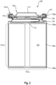
- the figs 1 and 2 show an energy storage cell 100 according to the invention with an airtight and liquid-tight sealed housing, which comprises a metallic housing cup 101 with a terminal circular opening and a cover assembly 102 with a circular edge 102a, which closes the circular opening.
- the cell further includes an annular gasket 103 of an electrically insulating material that encircles the circular rim 102a of the lid assembly 102 and electrically insulates the housing can 101 and the lid assembly 102 from each other.
- the housing cup 101 comprises in axial sequence a bottom 101a, a central section 101b and a closure section 101c, the central section 101b being cylindrical and in the central section 101b the winding casing 104c of the electrode-separator composite 104 designed as a winding with the inside of the housing cup 101 is in contact, and in the closing portion 101c, the annular gasket 103 is in press contact with the lid assembly 102 and the inside of the case cup 101. As shown in FIG.
- the housing cup 101 has in the closure section 101c an opening edge 101d defining the circular opening, which is bent radially inward over the edge 102a of the cover assembly 102 surrounded by the seal 103 and which holds the cover assembly 102 including the seal 103 in the circular opening of the housing cup 101 positively fixed.
- the opening edge 101d of the housing cup 101 which is bent radially inwards has a greater wall thickness than the housing cup 101 in the central section 101b. As a result, it is possible to perform welding operations on the opening edge 101d without damaging the gasket 103.
- the cell 100 also includes an electrode-separator assembly 104 in the form of a cylindrical coil with the sequence anode/separator/cathode, which is not shown here in detail. Only the longitudinal edge 106a of the anode current collector 106, which emerges from the end face 104a of the electrode-separator assembly 104, and the longitudinal edge 109a of the anode current collector 109, which emerges from the end face 104b of the electrode-separator assembly 104, can be seen.
- the longitudinal edge 106a is preferably welded directly to the housing base 101a over its entire length.
- the longitudinal edge 109a is preferably welded directly to the contact plate 112 over its entire length.
- the contact plate 112 is in turn connected via the electrical conductor 118 to the cover assembly 102, which is described in more detail below.
- the cell 100 usually has a height in the range from 60 mm to 10 mm, and its diameter is preferably in the range from 20 mm to 50 mm.
- the housing cup 101 usually has a wall thickness in the range of 0.1 mm to 0.3 mm in the central section 101b. The radial after The inside bent opening edge 101d of the housing cup 101 is made thicker than the housing cup 101 in the central portion 101b by a factor in the range of 1.5 to 2.
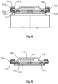
- the opening edge 101d is formed in two layers as a result of folding and has a U-shaped cross section.
- the double-layer opening edge 101d has the first layer 101e, which is in direct contact with the edge 102a of the cover assembly 102 enclosing seal 103, and the second layer 101f, which is on the side facing away from the seal 103 of the first layer 101e parallel to the first layer extends.
- the first layer 101e is delimited by the cut edge 101g, which points radially outwards and as a result is excellently protected against corrosion.
- the double-layer opening edge 101d comprises a first, inner side 101j, which is in direct contact with the seal 103, and a second side 101h, facing away from the seal 103.
- This second side 101h is in the form of an annular, flat surface and has a width d in the range from 1.2 mm to 4 mm. It encloses an angle of 90° with the wall of the housing cup 101 in the central section 101b.
- the opening edge 101d is formed in two layers as a result of folding and has a U-shaped cross section.
- the double-layered opening edge 101d has the first layer 101e, which is in direct contact with the edge 102a of the lid assembly 102, and the second layer 101f, which is on the side of the first layer 101e facing away from the gasket 103, parallel to the first layer Layer 101e extends.
- the second layer 101f is delimited by the cut edge 101g, which points radially outwards.
- the cover assembly 102 is shown, which in the embodiments of the energy storage cell 100 according to the invention according to the Figures 1 to 4 is used.
- This includes the disk 113 with the metallic membrane 114, which bulges outwards or bursts when there is overpressure within the housing.
- the disc 113 with the membrane 114 is in electrical and direct contact with the pole cap 117, which closes off the cover assembly 102 to the outside. Furthermore, it is in electrical contact with the inner contact disk 115, but only via the membrane 114. Otherwise, the disk 113 and the disk 115 are electrically insulated from one another by the insulator 116. If the membrane 114 bulges outwards as a result of excess pressure, which can act directly on the membrane via the opening 115a, the electrical contact between the disk 113 and the disk 115 breaks off. At high pressures, the membrane can also burst.
- the structure of the electrode-separator composite 104 is based on 6 illustrated.
- the assembly 104 comprises the strip-shaped anode 105 with the strip-shaped anode current collector 106, which has a first longitudinal edge 106a and a second longitudinal edge parallel thereto.
- the anode current collector 106 is a copper or nickel foil. This comprises a band-shaped main area which is loaded with a layer of negative electrode material 107 and a free edge strip 106b which extends along its first longitudinal edge 106a and which is not loaded with the electrode material 107.
- the assembly 104 comprises the strip-shaped cathode 108 with the strip-shaped cathode current collector 109, which has a first longitudinal edge 109a and a second longitudinal edge parallel thereto.
- the cathode current collector 109 is an aluminum foil. It comprises a ribbon-shaped main portion loaded with a layer of positive electrode material 110 and a free edge strip 109b which extends along its first longitudinal edge 109a and which is not loaded with the electrode material 110. Both electrodes are shown individually in the unwound state.
- the anode 105 and the cathode 108 are arranged offset to one another within the electrode-separator assembly 104, so that the first longitudinal edge 106a of the anode current collector 106 from the first terminal face 104a and the first longitudinal edge 109a of the cathode current collector 109 from the second terminal face 104b of the Electrode-separator composite 104 exits.
- the staggered arrangement can be seen in the illustration below left.
- the two strip-shaped separators 116 and 117 are also shown there, which separate the electrodes 105 and 108 from one another in the coil.
- the electrode-separator composite 104 is shown in wound form, as in an energy storage cell according to one of Figures 1 to 4 can be used.
- the electrode edges 106a and 109a emerging from the end faces 104a and 104b are clearly visible.
- the winding jacket 104c is formed by a plastic film.
Priority Applications (2)
| Application Number | Priority Date | Filing Date | Title |
|---|---|---|---|
| EP21210297.4A EP4187688A1 (fr) | 2021-11-24 | 2021-11-24 | Cellule d'accumulateur d'énergie, composite de cellules d'accumulateur d'énergie et procédé de fabrication |
| PCT/EP2022/083072 WO2023094498A1 (fr) | 2021-11-24 | 2022-11-24 | Cellule de stockage d'énergie, ensemble de cellules de stockage d'énergie et procédé de production |
Applications Claiming Priority (1)
| Application Number | Priority Date | Filing Date | Title |
|---|---|---|---|
| EP21210297.4A EP4187688A1 (fr) | 2021-11-24 | 2021-11-24 | Cellule d'accumulateur d'énergie, composite de cellules d'accumulateur d'énergie et procédé de fabrication |
Publications (1)
| Publication Number | Publication Date |
|---|---|
| EP4187688A1 true EP4187688A1 (fr) | 2023-05-31 |
Family
ID=78789758
Family Applications (1)
| Application Number | Title | Priority Date | Filing Date |
|---|---|---|---|
| EP21210297.4A Withdrawn EP4187688A1 (fr) | 2021-11-24 | 2021-11-24 | Cellule d'accumulateur d'énergie, composite de cellules d'accumulateur d'énergie et procédé de fabrication |
Country Status (2)
| Country | Link |
|---|---|
| EP (1) | EP4187688A1 (fr) |
| WO (1) | WO2023094498A1 (fr) |
Citations (5)
| Publication number | Priority date | Publication date | Assignee | Title |
|---|---|---|---|---|
| JP2007234305A (ja) * | 2006-02-28 | 2007-09-13 | Sanyo Electric Co Ltd | 円筒形電池 |
| JP2012174523A (ja) * | 2011-02-22 | 2012-09-10 | Toyota Motor Corp | 円筒型電池 |
| EP3188280A1 (fr) | 2016-01-04 | 2017-07-05 | Samsung SDI Co., Ltd | Ensemble de capot et batterie secondaire le comprenant |
| WO2017215900A1 (fr) | 2016-06-16 | 2017-12-21 | Varta Microbattery Gmbh | Cellule électrochimique à résistance intérieure optimisée |
| EP3537496A1 (fr) * | 2018-03-05 | 2019-09-11 | H&T Rechargeable LLC | Recipient de batterie pour une batterie |
-
2021
- 2021-11-24 EP EP21210297.4A patent/EP4187688A1/fr not_active Withdrawn
-
2022
- 2022-11-24 WO PCT/EP2022/083072 patent/WO2023094498A1/fr unknown
Patent Citations (5)
| Publication number | Priority date | Publication date | Assignee | Title |
|---|---|---|---|---|
| JP2007234305A (ja) * | 2006-02-28 | 2007-09-13 | Sanyo Electric Co Ltd | 円筒形電池 |
| JP2012174523A (ja) * | 2011-02-22 | 2012-09-10 | Toyota Motor Corp | 円筒型電池 |
| EP3188280A1 (fr) | 2016-01-04 | 2017-07-05 | Samsung SDI Co., Ltd | Ensemble de capot et batterie secondaire le comprenant |
| WO2017215900A1 (fr) | 2016-06-16 | 2017-12-21 | Varta Microbattery Gmbh | Cellule électrochimique à résistance intérieure optimisée |
| EP3537496A1 (fr) * | 2018-03-05 | 2019-09-11 | H&T Rechargeable LLC | Recipient de batterie pour une batterie |
Also Published As
| Publication number | Publication date |
|---|---|
| WO2023094498A1 (fr) | 2023-06-01 |
Similar Documents
| Publication | Publication Date | Title |
|---|---|---|
| EP3916877A1 (fr) | Élément d'accumulateur d'énergie et procédé de fabrication | |
| EP3916828A1 (fr) | Élément lithium-ion à haute densité énergétique spécifique | |
| WO2022034156A1 (fr) | Cellule de stockage d'énergie et procédé de production | |
| WO2022048969A1 (fr) | Cellule d'accumulateur d'énergie | |
| EP3916868A1 (fr) | Élément d'accumulateur d'énergie et procédé de fabrication | |
| EP4158712B1 (fr) | Élément lithium-ion à haute densité énergétique | |
| WO2022058342A1 (fr) | Élément lithium-ion à haute densité d'énergie spécifique | |
| EP4187688A1 (fr) | Cellule d'accumulateur d'énergie, composite de cellules d'accumulateur d'énergie et procédé de fabrication | |
| EP4143903A1 (fr) | Pile électrochimique au lithium-ion secondaire | |
| EP4169105A1 (fr) | Pile lithium-ion à haute densité d'énergie spécifique | |
| EP4333138A1 (fr) | Élément d'accumulation d'énergie et procédé de fabrication d'un tel élément d'accumulation d'énergie | |
| EP4135088A1 (fr) | Élément accumulateur d'énergie, composite constitué d'éléments accumulateurs d'énergie et procédé de fabrication | |
| EP4270614A1 (fr) | Élément d'accumulateur d'énergie | |
| WO2023016769A1 (fr) | Élément de stockage d'énergie, ensemble d'éléments de stockage d'énergie et processus de production | |
| EP4152434A1 (fr) | Élément accumulateur d'énergie | |
| EP4164049A1 (fr) | Élément d'accumulateur d'énergie et procédé de fabrication | |
| EP4164048A1 (fr) | Élément d'accumulateur d'énergie et procédé de fabrication | |
| EP4250412A1 (fr) | Cellule d'accumulateur d'énergie | |
| EP4266438A1 (fr) | Élément d'accumulateur d'énergie et procédé de fabrication | |
| EP4197051A1 (fr) | Cellule de stockage d'énergie et procédé de production | |
| EP4170812A1 (fr) | Cellule lithium-ion | |
| WO2023202987A1 (fr) | Cellule de stockage d'énergie comprenant un ensemble électrode-séparateur enroulé et son procédé de production | |
| EP4258397A1 (fr) | Élément d'accumulation d'énergie pourvu de boîtier cylindrique et procédé de fabrication | |
| EP4336632A1 (fr) | Dispositif d'accumulation d'énergie et procédé de fabrication d'un tel dispositif d'accumulation d'énergie | |
| EP4106062A1 (fr) | Élément et son procédé de fabrication |
Legal Events
| Date | Code | Title | Description |
|---|---|---|---|
| PUAI | Public reference made under article 153(3) epc to a published international application that has entered the european phase |
Free format text: ORIGINAL CODE: 0009012 |
|
| STAA | Information on the status of an ep patent application or granted ep patent |
Free format text: STATUS: THE APPLICATION HAS BEEN PUBLISHED |
|
| AK | Designated contracting states |
Kind code of ref document: A1 Designated state(s): AL AT BE BG CH CY CZ DE DK EE ES FI FR GB GR HR HU IE IS IT LI LT LU LV MC MK MT NL NO PL PT RO RS SE SI SK SM TR |
|
| STAA | Information on the status of an ep patent application or granted ep patent |
Free format text: STATUS: THE APPLICATION IS DEEMED TO BE WITHDRAWN |
|
| 18D | Application deemed to be withdrawn |
Effective date: 20231201 |