EP4265891A1 - System zum betreiben einer kühleinrichtung eines nutzfahrzeugs - Google Patents
System zum betreiben einer kühleinrichtung eines nutzfahrzeugs Download PDFInfo
- Publication number
- EP4265891A1 EP4265891A1 EP23163626.7A EP23163626A EP4265891A1 EP 4265891 A1 EP4265891 A1 EP 4265891A1 EP 23163626 A EP23163626 A EP 23163626A EP 4265891 A1 EP4265891 A1 EP 4265891A1
- Authority
- EP
- European Patent Office
- Prior art keywords
- pressure
- control
- actuator
- variable
- target
- Prior art date
- Legal status (The legal status is an assumption and is not a legal conclusion. Google has not performed a legal analysis and makes no representation as to the accuracy of the status listed.)
- Granted
Links
Images


Classifications
-
- F—MECHANICAL ENGINEERING; LIGHTING; HEATING; WEAPONS; BLASTING
- F01—MACHINES OR ENGINES IN GENERAL; ENGINE PLANTS IN GENERAL; STEAM ENGINES
- F01P—COOLING OF MACHINES OR ENGINES IN GENERAL; COOLING OF INTERNAL-COMBUSTION ENGINES
- F01P7/00—Controlling of coolant flow
- F01P7/02—Controlling of coolant flow the coolant being cooling-air
- F01P7/06—Controlling of coolant flow the coolant being cooling-air by varying blade pitch
-
- F—MECHANICAL ENGINEERING; LIGHTING; HEATING; WEAPONS; BLASTING
- F01—MACHINES OR ENGINES IN GENERAL; ENGINE PLANTS IN GENERAL; STEAM ENGINES
- F01P—COOLING OF MACHINES OR ENGINES IN GENERAL; COOLING OF INTERNAL-COMBUSTION ENGINES
- F01P5/00—Pumping cooling-air or liquid coolants
- F01P5/02—Pumping cooling-air; Arrangements of cooling-air pumps, e.g. fans or blowers
- F01P5/04—Pump-driving arrangements
-
- B—PERFORMING OPERATIONS; TRANSPORTING
- B60—VEHICLES IN GENERAL
- B60H—ARRANGEMENTS OF HEATING, COOLING, VENTILATING OR OTHER AIR-TREATING DEVICES SPECIALLY ADAPTED FOR PASSENGER OR GOODS SPACES OF VEHICLES
- B60H1/00—Heating, cooling or ventilating devices
- B60H1/00457—Ventilation unit, e.g. combined with a radiator
- B60H1/00464—The ventilator being of the axial type
-
- B—PERFORMING OPERATIONS; TRANSPORTING
- B60—VEHICLES IN GENERAL
- B60K—ARRANGEMENT OR MOUNTING OF PROPULSION UNITS OR OF TRANSMISSIONS IN VEHICLES; ARRANGEMENT OR MOUNTING OF PLURAL DIVERSE PRIME-MOVERS IN VEHICLES; AUXILIARY DRIVES FOR VEHICLES; INSTRUMENTATION OR DASHBOARDS FOR VEHICLES; ARRANGEMENTS IN CONNECTION WITH COOLING, AIR INTAKE, GAS EXHAUST OR FUEL SUPPLY OF PROPULSION UNITS IN VEHICLES
- B60K11/00—Arrangement in connection with cooling of propulsion units
- B60K11/02—Arrangement in connection with cooling of propulsion units with liquid cooling
-
- B—PERFORMING OPERATIONS; TRANSPORTING
- B60—VEHICLES IN GENERAL
- B60K—ARRANGEMENT OR MOUNTING OF PROPULSION UNITS OR OF TRANSMISSIONS IN VEHICLES; ARRANGEMENT OR MOUNTING OF PLURAL DIVERSE PRIME-MOVERS IN VEHICLES; AUXILIARY DRIVES FOR VEHICLES; INSTRUMENTATION OR DASHBOARDS FOR VEHICLES; ARRANGEMENTS IN CONNECTION WITH COOLING, AIR INTAKE, GAS EXHAUST OR FUEL SUPPLY OF PROPULSION UNITS IN VEHICLES
- B60K11/00—Arrangement in connection with cooling of propulsion units
- B60K11/06—Arrangement in connection with cooling of propulsion units with air cooling
-
- F—MECHANICAL ENGINEERING; LIGHTING; HEATING; WEAPONS; BLASTING
- F01—MACHINES OR ENGINES IN GENERAL; ENGINE PLANTS IN GENERAL; STEAM ENGINES
- F01P—COOLING OF MACHINES OR ENGINES IN GENERAL; COOLING OF INTERNAL-COMBUSTION ENGINES
- F01P3/00—Liquid cooling
- F01P3/20—Cooling circuits not specific to a single part of engine or machine
-
- F—MECHANICAL ENGINEERING; LIGHTING; HEATING; WEAPONS; BLASTING
- F04—POSITIVE - DISPLACEMENT MACHINES FOR LIQUIDS; PUMPS FOR LIQUIDS OR ELASTIC FLUIDS
- F04D—NON-POSITIVE-DISPLACEMENT PUMPS
- F04D27/00—Control, e.g. regulation, of pumps, pumping installations or pumping systems specially adapted for elastic fluids
- F04D27/02—Surge control
- F04D27/0246—Surge control by varying geometry within the pumps, e.g. by adjusting vanes
-
- F—MECHANICAL ENGINEERING; LIGHTING; HEATING; WEAPONS; BLASTING
- F04—POSITIVE - DISPLACEMENT MACHINES FOR LIQUIDS; PUMPS FOR LIQUIDS OR ELASTIC FLUIDS
- F04D—NON-POSITIVE-DISPLACEMENT PUMPS
- F04D29/00—Details, component parts, or accessories
- F04D29/26—Rotors specially for elastic fluids
- F04D29/32—Rotors specially for elastic fluids for axial flow pumps
- F04D29/34—Blade mountings
- F04D29/36—Blade mountings adjustable
- F04D29/362—Blade mountings adjustable during rotation
-
- B—PERFORMING OPERATIONS; TRANSPORTING
- B60—VEHICLES IN GENERAL
- B60K—ARRANGEMENT OR MOUNTING OF PROPULSION UNITS OR OF TRANSMISSIONS IN VEHICLES; ARRANGEMENT OR MOUNTING OF PLURAL DIVERSE PRIME-MOVERS IN VEHICLES; AUXILIARY DRIVES FOR VEHICLES; INSTRUMENTATION OR DASHBOARDS FOR VEHICLES; ARRANGEMENTS IN CONNECTION WITH COOLING, AIR INTAKE, GAS EXHAUST OR FUEL SUPPLY OF PROPULSION UNITS IN VEHICLES
- B60K25/00—Auxiliary drives
- B60K25/02—Auxiliary drives directly from an engine shaft
- B60K2025/022—Auxiliary drives directly from an engine shaft by a mechanical transmission
-
- B—PERFORMING OPERATIONS; TRANSPORTING
- B60—VEHICLES IN GENERAL
- B60Y—INDEXING SCHEME RELATING TO ASPECTS CROSS-CUTTING VEHICLE TECHNOLOGY
- B60Y2200/00—Type of vehicle
- B60Y2200/20—Off-Road Vehicles
- B60Y2200/22—Agricultural vehicles
-
- B—PERFORMING OPERATIONS; TRANSPORTING
- B60—VEHICLES IN GENERAL
- B60Y—INDEXING SCHEME RELATING TO ASPECTS CROSS-CUTTING VEHICLE TECHNOLOGY
- B60Y2200/00—Type of vehicle
- B60Y2200/40—Special vehicles
- B60Y2200/41—Construction vehicles, e.g. graders, excavators
-
- B—PERFORMING OPERATIONS; TRANSPORTING
- B60—VEHICLES IN GENERAL
- B60Y—INDEXING SCHEME RELATING TO ASPECTS CROSS-CUTTING VEHICLE TECHNOLOGY
- B60Y2400/00—Special features of vehicle units
- B60Y2400/30—Sensors
- B60Y2400/302—Temperature sensors
-
- B—PERFORMING OPERATIONS; TRANSPORTING
- B60—VEHICLES IN GENERAL
- B60Y—INDEXING SCHEME RELATING TO ASPECTS CROSS-CUTTING VEHICLE TECHNOLOGY
- B60Y2400/00—Special features of vehicle units
- B60Y2400/30—Sensors
- B60Y2400/306—Pressure sensors
-
- B—PERFORMING OPERATIONS; TRANSPORTING
- B60—VEHICLES IN GENERAL
- B60Y—INDEXING SCHEME RELATING TO ASPECTS CROSS-CUTTING VEHICLE TECHNOLOGY
- B60Y2400/00—Special features of vehicle units
- B60Y2400/40—Actuators for moving a controlled member
- B60Y2400/406—Hydraulic actuators
-
- F—MECHANICAL ENGINEERING; LIGHTING; HEATING; WEAPONS; BLASTING
- F01—MACHINES OR ENGINES IN GENERAL; ENGINE PLANTS IN GENERAL; STEAM ENGINES
- F01P—COOLING OF MACHINES OR ENGINES IN GENERAL; COOLING OF INTERNAL-COMBUSTION ENGINES
- F01P2025/00—Measuring
- F01P2025/08—Temperature
-
- F—MECHANICAL ENGINEERING; LIGHTING; HEATING; WEAPONS; BLASTING
- F05—INDEXING SCHEMES RELATING TO ENGINES OR PUMPS IN VARIOUS SUBCLASSES OF CLASSES F01-F04
- F05D—INDEXING SCHEME FOR ASPECTS RELATING TO NON-POSITIVE-DISPLACEMENT MACHINES OR ENGINES, GAS-TURBINES OR JET-PROPULSION PLANTS
- F05D2270/00—Control
- F05D2270/30—Control parameters, e.g. input parameters
- F05D2270/303—Temperature
Definitions
- the invention relates to a system for operating a cooling device of a commercial vehicle, comprising an axial fan that can be rotated by means of a fan drive to generate a cooling air flow which is used to act on a vehicle unit to be cooled, the axial fan having a plurality of fan blades which can be operated by deflection of a pressure-operated fan Allow the actuator to pivot with respect to an angle of attack, a temperature sensor for determining an actual value of a temperature variable that reflects a current operating temperature of the vehicle unit, and a control unit that compares the actual value of the temperature variable with a predetermined target value in order to determine a target value for actuation in accordance with a determined control deviation to output the control variable provided for the actuator.
- Such a system which is based purely on temperature control of an axial fan with adjustable fan blades to adjust the cooling capacity, is, for example, from DE 10 2019 003 713 A1 known. Since the operating temperature of an air-cooled vehicle unit reacts relatively slowly to changes in the cooling air flow, the result is an imprecise temperature control behavior that tends to overshoot in particular.
- the system for operating a cooling device of a commercial vehicle comprises an axial fan that can be rotated by means of a fan drive to generate a cooling air flow that serves to act on a vehicle unit to be cooled.
- the axial fan has a large number of fan blades, which can be pivoted with respect to an angle of attack by deflecting a pressure-operated actuator.
- the system includes a temperature sensor for determining an actual value of a temperature variable that reflects a current operating temperature of the vehicle unit, and a control unit that compares the actual value of the temperature variable with a predetermined target value in order to determine a target value for actuating the actuator in accordance with a determined control deviation to issue the intended tax variable.
- the control variable is a hydraulic or pneumatic actuation pressure provided for deflection of the actuator.
- the actuation pressure is not only possible with comparatively little technical effort using a conventional pressure sensor at any point leading to the actuator Pressure control line (and therefore away from moving parts of the axial fan) can be detected, but also allows a clear prediction of the angle of attack of the fan blades depending on the controlled actuation pressure to be made when the deflection and thus actuation behavior of the actuator is known.
- an electrically controllable pressure control valve is present for pressure actuation of the actuator, the control unit comparing the output target value of the control variable with a sensor-detected actual value in order to provide an electrical actuation signal in accordance with a determined control deviation To generate control of the pressure control valve.
- the system according to the invention thus comprises an arrangement of cascaded control loops.
- an outer control loop in which the control deviation determined for the temperature variable is minimized, there is also an inner control loop that is aimed at the actual regulation of the control variable using the pressure control valve.
- the pressure control valve is therefore part of the inner control loop, and possible tolerances with regard to its actuation behavior are also regulated as part of this.
- control variable i.e. the hydraulic or pneumatic actuation pressure applied to the actuator
- an electrically controllable pressure control valve to be present for pressure actuation of the actuator, with the control unit directly generating an electrical actuation signal representing the target value of the control variable for pre-control of the pressure control valve.
- the inner control loop is missing; rather, the expected actuation behavior of the pressure control valve is predictively included by the control unit when outputting the target value.
- the expected actuation behavior of the pressure control valve is determined in advance, for example, on the basis of simulations or empirical tests, and is stored in the form of a corresponding parameter set in a memory unit that communicates with the control unit.
- the pressure control valve is preferably designed as a 3/2-way solenoid valve for actuating a single-acting actuating cylinder included in the actuator.
- the single-acting actuating cylinder is structurally integrated into a fan hub of the axial fan and interacts with a spring-loaded restoring means in such a way that the fan blades lead to a minimum flow rate in the unpressurized operating state Take the angle of attack.
- a rotary feedthrough provided on the fan hub establishes a connection to the actuating cylinder via a pressure control line.
- the angle of attack of the fan blades can be deflected in the direction of an increasing flow rate against the effect of the restoring means.
- a targeted adjustment of the cooling capacity of the axial fan is possible by modulating the position of the 3/2-way solenoid valve between its two valve positions. In this case, pressure is applied to the actuating cylinder in a first valve position and the actuating cylinder is relieved of pressure in a second valve position.
- the vehicle unit to be cooled by means of the axial fan is part of an operating system of the commercial vehicle.
- the vehicle unit can have a traction drive with an internal combustion engine and/or electric motor, which is connected to driven wheels of the commercial vehicle via a transmission and/or is used to operate various work or additional functions of the commercial vehicle.
- it can also be peripheral components that need to be cooled, such as a hydraulic system, a turbocharger intended to operate the internal combustion engine, or an air conditioning system that is included in a cabin ventilation system.
- Each of the vehicle units can be assigned a separate liquid cooling circuit, in which there is a respective heat exchanger, which is passed through by the cooling air flow generated by the axial fan for the purpose of heat dissipation.
- a corresponding number of temperature sensors may be present be, whose sensor signals are linked together by the control unit to determine the actual value of the temperature variable in order to determine a combined cooling requirement of the various vehicle units by appropriately taking into account and weighting the associated operating temperatures.
- Fig. 1 shows a schematically illustrated exemplary embodiment of the system according to the invention for operating a cooling device of a commercial vehicle.
- the system 10 comprises a cooling device 12 with an axial fan 16 that can be rotated by means of a fan drive 14 to generate a cooling air flow 18, which serves to act on a vehicle unit 20 to be cooled.
- the axial fan 16 has a large number of fan blades 22 on, which can be pivoted with respect to an angle of attack ⁇ by deflection of a pressure-operated actuator 24.
- a pressure control valve 28 which can be electrically controlled by a control unit 26, serves to actuate the pressure of the actuator 24.
- the pressure control valve 28 is fed with pressurized hydraulic fluid from a hydraulic system 32 of the commercial vehicle 34 via an inlet 30, and a return line 36 opens into a reservoir included in the hydraulic system 32 38.
- the pressure control valve 28 is designed as a 3/2-way solenoid valve 40 for actuating a single-acting actuating cylinder 42 included in the actuator 24.
- the single-acting actuating cylinder 42 is structurally integrated into a fan hub 44 of the axial fan 16 (contrary to the view in Fig. 1 ) and interacts with a spring-loaded restoring means 46 in such a way that the fan blades 22 assume an angle of attack ⁇ leading to a minimum delivery flow in the unpressurized operating state.
- a rotary feedthrough 48 provided on the fan hub 44 establishes a connection to the actuating cylinder 42 via a pressure control line 50.
- the angle of attack ⁇ of the fan blades 22 can be deflected in the direction of an increasing flow rate against the effect of the restoring means 46.
- a targeted adjustment of the cooling capacity of the axial fan 16 is possible by modulating the position of the 3/2-way solenoid valve 40 between its two valve positions.
- pressure is applied via the inlet 30, and in a second valve position 40b, the pressure of the actuating cylinder 42 is relieved via the return 36 in the direction of the reservoir 38.
- the vehicle unit 20 to be cooled by means of the axial fan 16 is part of an operating system 52 of the commercial vehicle 34.
- the commercial vehicle 34 is, for example, an agricultural or forestry vehicle or a construction vehicle.
- the vehicle unit 20 has a traction drive 54 with an internal combustion and/or electric motor 56, which is connected to driven wheels 60 of the commercial vehicle 34 via a transmission 58 and/or is used to operate various work or additional functions of the commercial vehicle 34.
- the vehicle unit 20 is assigned a water or oil-carrying liquid cooling circuit 62, in which there is a coolant pump 64 and a heat exchanger 66, which is passed through by the cooling air flow 18 generated by the axial fan 16 for the purpose of heat dissipation.
- the axial fan 16 is set in rotation either via the fan drive 14 designed as a belt drive 68 by the combustion and/or electric motor 56 or by means of its own electric drive.
- the system 10 includes a temperature sensor 70 for determining an actual value T is a temperature variable that represents a current operating temperature of the vehicle unit 20.
- the actual value T is determined by the control unit 26 on the basis of the sensor signals provided by the temperature sensor 70.
- Fig. 1 Only a single vehicle unit 20 is shown, but it can also be peripheral components to be cooled, such as the hydraulic system 32, a turbocharger provided for operating the internal combustion engine 56 or an air conditioning system included in a cabin ventilation.
- Each of the vehicle units 20 is assigned a separate liquid cooling circuit 62, in which there is a respective heat exchanger 66, which is passed through by the cooling air flow 18 generated by the axial fan 16 for the purpose of heat dissipation.
- thermosensor 70 In the case of several separate liquid cooling circuits 62, there is a corresponding number of temperature sensors 70, the sensor signals of which are linked together by the control unit 26 to determine the actual value T is the temperature variable in order to determine a combined cooling requirement of the various vehicle units 20 by appropriately taking into account and weighting the associated operating temperatures to determine.
- the control unit 26 first compares the actual value T is of the temperature variable determined by means of the temperature sensor 70 with a predetermined setpoint T target in a first function block 72.
- the specification of the target value T should is based on a current cooling requirement of the vehicle unit 20.
- the current cooling requirement of the vehicle unit 20 is in the present case determined by a Engine control unit 74 (see Fig. 1 ) determined and transmitted to the control unit 26 for the corresponding determination of the setpoint T should of the temperature variable.
- control unit 26 determines in a second function block 76 a target value p target for the actuating pressure to be controlled at the actuator 24.
- a comparison of the target value p target output in the second function block 76 is carried out with an actual value p ist of the actuation pressure detected in the pressure control line 50 of the actuator 24 by means of a pressure sensor 80, the control unit 26 in a fourth function block 82 according to the requirements a control deviation determined in the third function block 78 between the actual value p and the target value p target of the actuation pressure generates an electrical actuation signal for controlling the pressure control valve 28.
- a control curve provided for generating the electrical actuation signal is stored in a memory unit 84 (see Fig. 1 ) deposited.
- the system 10 thus comprises an arrangement of cascaded control loops.
- an outer control loop 86 in which the control deviation determined for the temperature variable is minimized, there is also an inner control loop 88, which is aimed at the actual regulation of the actuation pressure by means of the pressure control valve 28.
- the pressure control valve 28 is therefore part of the inner control loop 88, and possible tolerances with regard to its actuation behavior are also regulated as part of this.
- a second functional embodiment of the system 10 is in Fig. 3 reproduced.
- the control unit 26 in a third function block 90 directly generates an electrical actuation signal representing the target value p target of the actuation pressure for pre-control of the pressure control valve 28.
- the first and second function blocks 72, 76 are present unchanged, but the inner control loop 88 and thus also the pressure sensor 80 required for this are missing.
- the expected actuation behavior of the pressure control valve 28 is determined by the control unit 26 when outputting the target value p target included in the third function block 90 in a predictive manner.
- the expected actuation behavior of the pressure control valve 28 is determined in advance on the basis of simulations or empirical tests and is stored in the form of a corresponding parameter set in the memory unit 84 that communicates with the control unit 26.
Landscapes
- Engineering & Computer Science (AREA)
- Mechanical Engineering (AREA)
- Chemical & Material Sciences (AREA)
- Combustion & Propulsion (AREA)
- General Engineering & Computer Science (AREA)
- Transportation (AREA)
- Physics & Mathematics (AREA)
- Thermal Sciences (AREA)
- Geometry (AREA)
- Cooling, Air Intake And Gas Exhaust, And Fuel Tank Arrangements In Propulsion Units (AREA)
Abstract
Description
- Die Erfindung betrifft ein System zum Betreiben einer Kühleinrichtung eines Nutzfahrzeugs, umfassend einen mittels eines Lüfterantriebs in Drehung versetzbaren Axiallüfter zur Erzeugung eines Kühlluftstroms, der der Beaufschlagung eines zu kühlenden Fahrzeugaggregats dient, wobei der Axiallüfter eine Vielzahl von Lüfterflügeln aufweist, die sich durch Auslenkung eines druckbetätigbaren Aktuators bezüglich eines Anstellwinkels verschwenken lassen, einen Temperatursensor zur Bestimmung eines Istwerts einer Temperaturgröße, die eine aktuelle Betriebstemperatur des Fahrzeugaggregats wiedergibt, und eine Kontrolleinheit, die den Istwert der Temperaturgröße mit einem vorgegebenen Sollwert vergleicht, um nach Maßgabe einer ermittelten Regelabweichung einen Zielwert einer zur Betätigung des Aktuators vorgesehenen Steuergröße auszugeben.
- Ein derartiges System, das auf einer reinen Temperaturregelung eines Axiallüfters mit verstellbaren Lüfterflügeln zur Kühlleistungsanpassung beruht, ist beispielsweise aus der
DE 10 2019 003 713 A1 bekannt. Da die Betriebstemperatur eines luftgekühlten Fahrzeugaggregats verhältnismäßig träge auf Veränderungen des Kühlluftstroms reagiert, ist ein unpräzises, insbesondere zum Überschwingen neigendes Temperaturregelverhalten die Folge. - Um das Regelverhalten zu verbessern, ist es daher bekannt, zusätzlich einen unterlagerten Regelkreis vorzusehen, der der Einregelung des Anstellwinkels der Lüfterflügel, genauer gesagt einer zur Verstellung der Lüfterflügel an einem Aktuator auftretenden Auslenkung dient. Die zur Einregelung des Anstellwinkels erforderliche sensorische Erfassung der Auslenkung ist vergleichsweise aufwändig, denn diese tritt an einem sich drehenden Teil des Axiallüfters, namentlich an einer die Lüfterflügel tragenden Lüfternabe auf, in die der Aktuator baulich integriert ist.
- Es ist daher Aufgabe der vorliegenden Erfindung, ein System der eingangs genannten Art hinsichtlich der Erzielung eines präzisen Regelverhaltens bei zugleich verringertem technischen Aufwand anzugeben.
- Diese Aufgabe wird durch ein System zum Betreiben einer Kühleinrichtung eines Nutzfahrzeugs mit den Merkmalen des Patentanspruchs 1 gelöst.
- Das System zum Betreiben einer Kühleinrichtung eines Nutzfahrzeugs umfasst einen mittels eines Lüfterantriebs in Drehung versetzbaren Axiallüfter zur Erzeugung eines Kühlluftstroms, der der Beaufschlagung eines zu kühlenden Fahrzeugaggregats dient. Hierbei weist der Axiallüfter eine Vielzahl von Lüfterflügeln auf, die sich durch Auslenkung eines druckbetätigbaren Aktuators bezüglich eines Anstellwinkels verschwenken lassen. Des Weiteren umfasst das System einen Temperatursensor zur Bestimmung eines Istwerts einer Temperaturgröße, die eine aktuelle Betriebstemperatur des Fahrzeugaggregats wiedergibt, und eine Kontrolleinheit, die den Istwert der Temperaturgröße mit einem vorgegebenen Sollwert vergleicht, um nach Maßgabe einer ermittelten Regelabweichung einen Zielwert einer zur Betätigung des Aktuators vorgesehenen Steuergröße auszugeben. Erfindungsgemäß handelt es sich bei der Steuergröße um einen zur Auslenkung des Aktuators vorgesehenen hydraulischen oder pneumatischen Betätigungsdruck.
- Der Betätigungsdruck ist nicht nur mit vergleichsweise geringem technischen Aufwand mittels eines herkömmlichen Drucksensors an beliebiger Stelle einer zum Aktuator führenden Drucksteuerleitung (und damit abseits bewegter Teile des Axiallüfters) erfassbar, sondern erlaubt es zudem bei bekanntem Auslenkungs- und damit Stellverhalten des Aktuators, eine eindeutige Vorhersage des sich abhängig vom eingesteuerten Betätigungsdruck ergebenden Anstellwinkels der Lüfterflügel zu treffen.
- Dies eröffnet unterschiedliche Möglichkeiten, um zu einer präzisen Einstellung des mittels des Axiallüfters erzeugbaren Kühlluftstroms zu gelangen.
- So kann in einer ersten funktionellen Ausgestaltung des erfindungsgemäßen Systems vorgesehen sein, dass ein elektrisch steuerbares Druckregelventil zur Druckbetätigung des Aktuators vorhanden ist, wobei die Kontrolleinheit den ausgegebenen Zielwert der Steuergröße mit einem sensorisch erfassten Istwert vergleicht, um nach Maßgabe einer ermittelten Regelabweichung ein elektrisches Betätigungssignal zur Ansteuerung des Druckregelventils zu erzeugen.
- Bei diesem Ansatz umfasst das erfindungsgemäße System somit eine Anordnung kaskadierter Regelschleifen. Neben einer äußeren Regelschleife, in der eine Minimierung der für die Temperaturgröße ermittelten Regelabweichung erfolgt, ist ferner eine innere Regelschleife vorhanden, die auf die eigentliche Einregelung der Steuergröße mittels des Druckregelventils gerichtet ist. Das Druckregelventil ist damit Bestandteil der inneren Regelschleife, mögliche Toleranzen hinsichtlich seines Betätigungsverhaltens werden im Rahmen dessen mit ausgeregelt.
- Die Erfassung des Istwerts der Steuergröße, mithin des am Aktuator anliegenden hydraulischen oder pneumatischen Betätigungsdrucks erfolgt hierbei mittels eines mit der Kontrolleinheit in Verbindung stehenden Drucksensors.
- In einer zweiten funktionellen Ausgestaltung des erfindungsgemäßen Systems besteht die Möglichkeit, dass ein elektrisch steuerbares Druckregelventil zur Druckbetätigung des Aktuators vorhanden ist, wobei die Kontrolleinheit unmittelbar ein den Zielwert der Steuergröße repräsentierendes elektrisches Betätigungssignal zur Vorsteuerung des Druckregelventils erzeugt.
- Bei diesem Ansatz fehlt die innere Regelschleife, vielmehr wird das zu erwartende Betätigungsverhalten des Druckregelventils von der Kontrolleinheit bei der Ausgabe des Zielwerts prädiktiv mit einbezogen. Das zu erwartende Betätigungsverhalten des Druckregelventils wird beispielsweise vorab auf Grundlage von Simulationen oder empirischen Versuchen ermittelt, und ist in Form eines damit korrespondierenden Parametersatzes in einer mit der Kontrolleinheit kommunizierenden Speichereinheit hinterlegt.
- Vorzugsweise ist das Druckregelventil als 3/2-Wege-Magnetventil zur Betätigung eines von dem Aktuator umfassten einfachwirkenden Stellzylinders ausgebildet. Der einfachwirkende Stellzylinder ist in eine Lüfternabe des Axiallüfters baulich integriert und wirkt mit einem federbelasteten Rückstellmittel derart zusammen, dass die Lüfterflügel in drucklosem Betätigungszustand einen zu einem minimalen Förderstrom führenden Anstellwinkel einnehmen. Eine an der Lüfternabe vorgesehene Drehdurchführung stellt über eine Drucksteuerleitung eine Verbindung mit dem Stellzylinder her.
- Durch Aufbau eines entsprechenden Betätigungsdrucks im Stellzylinder lässt sich der Anstellwinkel der Lüfterflügel entgegen der Wirkung des Rückstellmittels in Richtung eines zunehmenden Förderstroms auslenken. Auf diese Weise ist eine gezielte Anpassung der Kühlleistung des Axiallüfters durch Modulation der Stellung des 3/2-Wege-Magnetventils zwischen seinen beiden Ventilstellungen möglich. Hierbei erfolgt in einer ersten Ventilstellung eine Druckbeaufschlagung, in einer zweiten Ventilstellung eine Druckentlastung des Stellzylinders.
- Typischerweise ist das mittels des Axiallüfters zu kühlende Fahrzeugaggregat Bestandteil eines Betriebssystems des Nutzfahrzeugs. Das Fahrzeugaggregat kann einen Fahrantrieb mit einem Verbrennungs- und/oder Elektromotor aufweisen, der über ein Getriebe mit angetriebenen Rädern des Nutzfahrzeugs in Verbindung steht und/oder dem Betrieb diverser Arbeits- oder Zusatzfunktionen des Nutzfahrzeugs dient. Daneben kann es sich auch um zu kühlende periphere Komponenten wie ein Hydrauliksystem, einen zum Betrieb des Verbrennungsmotors vorgesehenen Turbolader oder eine von einer Kabinenlüftung umfasste Klimaanlage handeln. Jedem der Fahrzeugaggregate kann ein separater Flüssigkeitskühlkreislauf zugeordnet sein, in dem sich ein jeweiliger Wärmetauscher befindet, der zum Zwecke der Wärmeabfuhr von dem mittels des Axiallüfters erzeugten Kühlluftstrom durchsetzt wird.
- Im Falle mehrerer separater Flüssigkeitskühlkreisläufe kann eine entsprechende Anzahl von Temperatursensoren vorhanden sein, deren Sensorsignale von der Kontrolleinheit zur Bestimmung des Istwerts der Temperaturgröße miteinander verknüpft werden, um einen kombinierten Kühlbedarf der verschiedenen Fahrzeugaggregate durch entsprechende Berücksichtigung und Gewichtung der jeweils zugehörigen Betriebstemperaturen zu bestimmen.
- Das erfindungsgemäße System zum Betreiben einer Kühleinrichtung eines Nutzfahrzeugs wird im Folgenden anhand der beigefügten Zeichnungen näher beschrieben. Dabei beziehen sich identische Bezugszeichen auf übereinstimmende oder bezüglich ihrer Funktion vergleichbare Komponenten. Es zeigen:
- Fig. 1
- ein schematisch dargestelltes Ausführungsbeispiel des erfindungsgemäßen Systems zum Betreiben einer Kühleinrichtung eines Nutzfahrzeugs,
- Fig. 2
- eine als Ablaufdiagramm veranschaulichte erste funktionelle Ausgestaltung des in
Fig. 1 wiedergegebenen erfindungsgemäßen Systems, und - Fig. 3
- eine als Ablaufdiagramm veranschaulichte zweite funktionelle Ausgestaltung des in
Fig. 1 wiedergegebenen erfindungsgemäßen Systems. -
Fig. 1 zeigt ein schematisch dargestelltes Ausführungsbeispiel des erfindungsgemäßen Systems zum Betreiben einer Kühleinrichtung eines Nutzfahrzeugs. - Demgemäß umfasst das System 10 eine Kühleinrichtung 12 mit einem mittels eines Lüfterantriebs 14 in Drehung versetzbaren Axiallüfter 16 zur Erzeugung eines Kühlluftstroms 18, der der Beaufschlagung eines zu kühlenden Fahrzeugaggregats 20 dient. Der Axiallüfter 16 weist eine Vielzahl von Lüfterflügeln 22 auf, die sich durch Auslenkung eines druckbetätigbaren Aktuators 24 bezüglich eines Anstellwinkels α verschwenken lassen.
- Ein von einer Kontrolleinheit 26 elektrisch steuerbares Druckregelventil 28 dient der Druckbetätigung des Aktuators 24. Das Druckregelventil 28 wird über einen Zulauf 30 mit unter Druck stehender Hydraulikflüssigkeit aus einem Hydrauliksystem 32 des Nutzfahrzeugs 34 gespeist, ein Rücklauf 36 mündet in ein von dem Hydrauliksystem 32 umfasstes Reservoir 38.
- Genauer gesagt ist das Druckregelventil 28 als 3/2-Wege-Magnetventil 40 zur Betätigung eines von dem Aktuator 24 umfassten einfachwirkenden Stellzylinders 42 ausgebildet. Der einfachwirkende Stellzylinder 42 ist in eine Lüfternabe 44 des Axiallüfters 16 baulich integriert (entgegen der aus Übersichtlichkeitsgründen gewählten Ansicht in
Fig. 1 ) und wirkt mit einem federbelasteten Rückstellmittel 46 derart zusammen, dass die Lüfterflügel 22 in drucklosem Betätigungszustand einen zu einem minimalen Förderstrom führenden Anstellwinkel α einnehmen. Eine an der Lüfternabe 44 vorgesehene Drehdurchführung 48 stellt über eine Drucksteuerleitung 50 eine Verbindung mit dem Stellzylinder 42 her. - Durch Aufbau eines entsprechenden Betätigungsdrucks im Stellzylinder 42 als Steuergröße lässt sich der Anstellwinkel α der Lüfterflügel 22 entgegen der Wirkung des Rückstellmittels 46 in Richtung eines zunehmenden Förderstroms auslenken. Auf diese Weise ist eine gezielte Anpassung der Kühlleistung des Axiallüfters 16 durch Modulation der Stellung des 3/2-Wege-Magnetventils 40 zwischen seinen beiden Ventilstellungen möglich. Hierbei erfolgt in einer ersten Ventilstellung 40a eine Druckbeaufschlagung über den Zulauf 30, in einer zweiten Ventilstellung 40b über den Rücklauf 36 eine Druckentlastung des Stellzylinders 42 in Richtung des Reservoirs 38.
- Es sei angemerkt, dass anstelle der beschriebenen hydraulischen auch eine pneumatische Druckbetätigung des Aktuators 24 denkbar ist.
- Das mittels des Axiallüfters 16 zu kühlende Fahrzeugaggregat 20 ist Bestandteil eines Betriebssystems 52 des Nutzfahrzeugs 34. Bei dem nicht näher dargestellten Nutzfahrzeug 34 handelt es sich beispielsweise um ein land- oder forstwirtschaftliches Fahrzeug bzw. ein Baufahrzeug.
- Beispielhaft weist das Fahrzeugaggregat 20 einen Fahrantrieb 54 mit einem Verbrennungs- und/oder Elektromotor 56 auf, der über ein Getriebe 58 mit angetriebenen Rädern 60 des Nutzfahrzeugs 34 in Verbindung steht und/oder dem Betrieb diverser Arbeits- oder Zusatzfunktionen des Nutzfahrzeugs 34 dient. Dem Fahrzeugaggregat 20 ist ein wasser- oder ölführender Flüssigkeitskühlkreislauf 62 zugeordnet, in dem sich eine Kühlmittelpumpe 64 sowie ein Wärmetauscher 66 befindet, der zum Zwecke der Wärmeabfuhr von dem mittels des Axiallüfters 16 erzeugten Kühlluftstrom 18 durchsetzt wird. Hierzu wird der Axiallüfter 16 entweder über den als Riementrieb 68 ausgebildeten Lüfterantrieb 14 seitens des Verbrennungs- und/oder Elektromotors 56 oder aber mittels eines eigenen elektrischen Antriebs in Drehung versetzt.
- Des Weiteren umfasst das System 10 einen Temperatursensor 70 zur Bestimmung eines eine aktuelle Betriebstemperatur des Fahrzeugaggregats 20 wiedergebenden Istwerts Tist einer Temperaturgröße. Die Bestimmung des Istwerts Tist erfolgt seitens der Kontrolleinheit 26 auf Grundlage der von dem Temperatursensor 70 bereitgestellten Sensorsignale.
- Der Übersichtlichkeit halber ist in
Fig. 1 lediglich ein einzelnes Fahrzeugaggregat 20 gezeigt, daneben kann es sich jedoch auch um zu kühlende periphere Komponenten wie das Hydrauliksystem 32, einen zum Betrieb des Verbrennungsmotors 56 vorgesehenen Turbolader oder eine von einer Kabinenlüftung umfasste Klimaanlage handeln. Jedem der Fahrzeugaggregate 20 ist ein separater Flüssigkeitskühlkreislauf 62 zugeordnet, in dem sich ein jeweiliger Wärmetauscher 66 befindet, der zum Zwecke der Wärmeabfuhr von dem mittels des Axiallüfters 16 erzeugten Kühlluftstrom 18 durchsetzt wird. - Im Falle mehrerer separater Flüssigkeitskühlkreisläufe 62 ist eine entsprechende Anzahl von Temperatursensoren 70 vorhanden, deren Sensorsignale von der Kontrolleinheit 26 zur Bestimmung des Istwerts Tist der Temperaturgröße miteinander verknüpft werden, um einen kombinierten Kühlbedarf der verschiedenen Fahrzeugaggregate 20 durch entsprechende Berücksichtigung und Gewichtung der jeweils zugehörigen Betriebstemperaturen zu bestimmen.
- Weitere strukturelle Details ergeben sich in Zusammenhang mit den beiden nachfolgend erläuterten funktionellen Ausgestaltungen des in
Fig. 1 abgebildeten Systems. - So ist in einer in
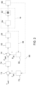
Fig. 2 gezeigten ersten funktionellen Ausgestaltung des Systems 10 vorgesehen, dass die Kontrolleinheit 26 zunächst in einem ersten Funktionsblock 72 den mittels des Temperatursensors 70 bestimmten Istwert Tist der Temperaturgröße mit einem vorgegebenen Sollwert Tsoll vergleicht. Die Vorgabe des Sollwerts Tsoll erfolgt hierbei aufgrund eines aktuellen Kühlbedarfs des Fahrzeugaggregats 20. Der aktuelle Kühlbedarf des Fahrzeugaggregats 20 wird vorliegend von einem Motorsteuergerät 74 (sieheFig. 1 ) bestimmt sowie zur entsprechenden Festlegung des Sollwerts Tsoll der Temperaturgröße an die Kontrolleinheit 26 übermittelt. - Nach Maßgabe einer im ersten Funktionsblock 72 ermittelten Regelabweichung zwischen dem Istwert Tist und dem Sollwert Tsoll der Temperaturgröße bestimmt die Kontrolleinheit 26 anschließend in einem zweiten Funktionsblock 76 einen Zielwert pziel für den am Aktuator 24 einzusteuernden Betätigungsdruck.
- Darauf aufbauend erfolgt in einem dritten Funktionsblock 78 ein Vergleich des im zweiten Funktionsblock 76 ausgegebenen Zielwerts pziel mit einem in der Drucksteuerleitung 50 des Aktuators 24 mittels eines Drucksensors 80 erfassten Istwerts pist des Betätigungsdrucks, wobei die Kontrolleinheit 26 in einem vierten Funktionsblock 82 nach Maßgabe einer im dritten Funktionsblock 78 ermittelten Regelabweichung zwischen dem Istwert pist und dem Zielwert pziel des Betätigungsdrucks ein elektrisches Betätigungssignal zur Ansteuerung des Druckregelventils 28 erzeugt. Eine zur Erzeugung des elektrischen Betätigungssignals vorgesehene Steuerkurve ist in einer mit der Kontrolleinheit 26 in Verbindung stehenden Speichereinheit 84 (siehe
Fig. 1 ) hinterlegt. - Bei diesem Ansatz umfasst das System 10 somit eine Anordnung kaskadierter Regelschleifen. Neben einer äußeren Regelschleife 86, in der eine Minimierung der für die Temperaturgröße ermittelten Regelabweichung erfolgt, ist ferner eine innere Regelschleife 88 vorhanden, die auf die eigentliche Einregelung des Betätigungsdrucks mittels des Druckregelventils 28 gerichtet ist. Das Druckregelventil 28 ist damit Bestandteil der inneren Regelschleife 88, mögliche Toleranzen hinsichtlich seines Betätigungsverhaltens werden im Rahmen dessen mit ausgeregelt.
- Eine zweite funktionelle Ausgestaltung des Systems 10 ist in
Fig. 3 wiedergegeben. Hier ist vorgesehen, dass die Kontrolleinheit 26 in einem dritten Funktionsblock 90 unmittelbar ein den Zielwert pziel des Betätigungsdrucks repräsentierendes elektrisches Betätigungssignal zur Vorsteuerung des Druckregelventils 28 erzeugt. Bei diesem Ansatz ist der erste wie auch zweite Funktionsblock 72, 76 unverändert vorhanden, es fehlt jedoch die innere Regelschleife 88 und damit auch der hierfür erforderliche Drucksensor 80. Vielmehr wird das zu erwartende Betätigungsverhalten des Druckregelventils 28 von der Kontrolleinheit 26 bei der Ausgabe des Zielwerts pziel im dritten Funktionsblock 90 prädiktiv mit einbezogen. Das zu erwartende Betätigungsverhalten des Druckregelventils 28 wird vorab auf Grundlage von Simulationen oder empirischen Versuchen ermittelt, und ist in Form eines damit korrespondierenden Parametersatzes in der mit der Kontrolleinheit 26 kommunizierenden Speichereinheit 84 hinterlegt.
Claims (5)
- System zum Betreiben einer Kühleinrichtung eines Nutzfahrzeugs, umfassendeinen mittels eines Lüfterantriebs (14) in Drehung versetzbaren Axiallüfter (16) zur Erzeugung eines Kühlluftstroms (18), der der Beaufschlagung eines zu kühlenden Fahrzeugaggregats (20) dient, wobei der Axiallüfter (16) eine Vielzahl von Lüfterflügeln (22) aufweist, die sich durch Auslenkung eines druckbetätigbaren Aktuators (24) bezüglich eines Anstellwinkels (α) verschwenken lassen,einen Temperatursensor (70) zur Bestimmung eines Istwerts (Tist) einer Temperaturgröße, die eine aktuelle Betriebstemperatur des Fahrzeugaggregats (20) wiedergibt, undeine Kontrolleinheit (26), die den Istwert (Tist) der Temperaturgröße mit einem vorgegebenen Sollwert (Tsoll) vergleicht, um nach Maßgabe einer ermittelten Regelabweichung einen Zielwert (pziel) einer zur Betätigung des Aktuators (24) vorgesehenen Steuergröße auszugeben, dadurch gekennzeichnet, dass es sich bei der Steuergröße um einen zur Auslenkung des Aktuators (24) vorgesehenen hydraulischen oder pneumatischen Betätigungsdruck handelt.
- System nach Anspruch 1, dadurch gekennzeichnet, dass ein elektrisch steuerbares Druckregelventil (28) zur Druckbetätigung des Aktuators (24) vorhanden ist, wobei die Kontrolleinheit (26) den ausgegebenen Zielwert (pziel) der Steuergröße mit einem sensorisch erfassten Istwert (pist) vergleicht, um nach Maßgabe einer ermittelten Regelabweichung ein elektrisches Betätigungssignal zur Ansteuerung des Druckregelventils (28) zu erzeugen.
- System nach Anspruch 1, dadurch gekennzeichnet, dass ein elektrisch steuerbares Druckregelventil (28) zur Druckbetätigung des Aktuators (24) vorhanden ist, wobei die Kontrolleinheit (26) unmittelbar ein den Zielwert (pziel) der Steuergröße repräsentierendes elektrisches Betätigungssignal zur Vorsteuerung des Druckregelventils (28) erzeugt.
- System nach Anspruch 2 oder 3, dadurch gekennzeichnet, dass das Druckregelventil (28) als 3/2-Wege-Magnetventil (40) zur Betätigung eines von dem Aktuator (24) umfassten einfachwirkenden Stellzylinders (42) ausgebildet ist.
- System nach wenigstens einem der vorhergehenden Ansprüche, dadurch gekennzeichnet, dass das mittels des Axiallüfters (16) zu kühlende Fahrzeugaggregat (20) Bestandteil eines Betriebssystems (52) des Nutzfahrzeugs (34) ist.
Applications Claiming Priority (1)
| Application Number | Priority Date | Filing Date | Title |
|---|---|---|---|
| DE102022109600.9A DE102022109600A1 (de) | 2022-04-21 | 2022-04-21 | System zum Betreiben einer Kühleinrichtung eines Nutzfahrzeugs |
Publications (2)
| Publication Number | Publication Date |
|---|---|
| EP4265891A1 true EP4265891A1 (de) | 2023-10-25 |
| EP4265891B1 EP4265891B1 (de) | 2025-08-13 |
Family
ID=88069675
Family Applications (1)
| Application Number | Title | Priority Date | Filing Date |
|---|---|---|---|
| EP23163626.7A Active EP4265891B1 (de) | 2022-04-21 | 2023-03-23 | System zum betreiben einer kühleinrichtung eines nutzfahrzeugs |
Country Status (3)
| Country | Link |
|---|---|
| US (1) | US12503971B2 (de) |
| EP (1) | EP4265891B1 (de) |
| DE (1) | DE102022109600A1 (de) |
Citations (4)
| Publication number | Priority date | Publication date | Assignee | Title |
|---|---|---|---|---|
| US2189888A (en) * | 1938-02-07 | 1940-02-13 | Fairbanks Morse & Co | Thermal control of internal combustion engines |
| US20050100444A1 (en) * | 2003-10-20 | 2005-05-12 | Flexxaire Manufacturing Inc. | Control system for variable pitch fan |
| US20200318584A1 (en) * | 2019-04-04 | 2020-10-08 | Deere And Company | Air intake screen debris sensing |
| DE102019003713A1 (de) | 2019-05-25 | 2020-11-26 | Deere & Company | Kühleinrichtung eines Antriebssystems für ein Fahrzeug |
Family Cites Families (8)
| Publication number | Priority date | Publication date | Assignee | Title |
|---|---|---|---|---|
| US2734493A (en) * | 1956-02-14 | Variable and reversible pitch fan for | ||
| US2826395A (en) * | 1954-07-19 | 1958-03-11 | Hudson Engineering Corp | Atmospheric heat exchange apparatus and fan therefor |
| US6253716B1 (en) * | 1999-07-07 | 2001-07-03 | Horton, Inc. | Control system for cooling fan assembly having variable pitch blades |
| US6729844B2 (en) * | 2002-08-14 | 2004-05-04 | Harold Ray Bettencourt | Controller for variable pitch fan system |
| US7008184B2 (en) * | 2002-08-14 | 2006-03-07 | Bettencourt Jr Harold Ray | Control for cooling fan |
| CN107139713B (zh) * | 2017-06-08 | 2024-04-16 | 龙口中宇热管理系统科技有限公司 | 基于可变角度液压风扇的智能散热系统及控制方案 |
| US11668228B2 (en) * | 2020-05-28 | 2023-06-06 | Deere & Company | Variable pitch fan control system |
| CN116658286A (zh) * | 2023-05-22 | 2023-08-29 | 上海嵩韬智能科技有限公司 | 一种发动机风扇桨距角实时控制的方法 |
-
2022
- 2022-04-21 DE DE102022109600.9A patent/DE102022109600A1/de active Pending
-
2023
- 2023-03-23 EP EP23163626.7A patent/EP4265891B1/de active Active
- 2023-04-19 US US18/303,406 patent/US12503971B2/en active Active
Patent Citations (4)
| Publication number | Priority date | Publication date | Assignee | Title |
|---|---|---|---|---|
| US2189888A (en) * | 1938-02-07 | 1940-02-13 | Fairbanks Morse & Co | Thermal control of internal combustion engines |
| US20050100444A1 (en) * | 2003-10-20 | 2005-05-12 | Flexxaire Manufacturing Inc. | Control system for variable pitch fan |
| US20200318584A1 (en) * | 2019-04-04 | 2020-10-08 | Deere And Company | Air intake screen debris sensing |
| DE102019003713A1 (de) | 2019-05-25 | 2020-11-26 | Deere & Company | Kühleinrichtung eines Antriebssystems für ein Fahrzeug |
Also Published As
| Publication number | Publication date |
|---|---|
| US12503971B2 (en) | 2025-12-23 |
| DE102022109600A1 (de) | 2023-10-26 |
| US20230340901A1 (en) | 2023-10-26 |
| EP4265891B1 (de) | 2025-08-13 |
Similar Documents
| Publication | Publication Date | Title |
|---|---|---|
| DE60317399T2 (de) | Regelbare Verdrängerpump sowie Steursystem dafür | |
| DE69013599T2 (de) | Kraftfahrzeug-Regelsysteme. | |
| DE4127250C2 (de) | Einrichtung zum Verteilen eines Fluiddruckes | |
| DE102008058692A1 (de) | Hydraulikanordnung mit einem Regelkreis zur Steuerung eines Fahrzeuggetriebes mit automatisierter Betätigung von Kupplungen | |
| EP3748168B1 (de) | Hydraulisches antriebssystem mit zwei pumpen und energierückgewinnung | |
| DE10000110B4 (de) | Hydrostatischer Fahrzeugantrieb mit Steuerungseinrichtung und Steuerungseinrichtung für hydrostatische Antriebe | |
| EP3880975B1 (de) | Elektrohydrostatisches aktuatorsystem | |
| DE3347000A1 (de) | Elektrohydraulische einrichtung zur steuerung eines doppeltwirkenden hydromotors | |
| EP2883788A1 (de) | Propellereinheit mit Regler | |
| DE102019106494B4 (de) | Druckregelventil und Vorrichtung mit einem derartigen Druckregelventil zum Steuern oder Regeln eines Drucks eines Druckfluids in einem Pilotdruckraum | |
| DE102015211305B3 (de) | Druckabhängig einlegbare Parksperre für hydraulisches Schaltgetriebe | |
| DE102017202273B4 (de) | Hydrostatisches Getriebe und Verfahren zur Bremsung damit | |
| EP4407156A2 (de) | Hydrauliksystem für eine landwirtschaftliche arbeitsmaschine | |
| DE102012012977A1 (de) | Hydraulischer Antrieb | |
| EP4265891B1 (de) | System zum betreiben einer kühleinrichtung eines nutzfahrzeugs | |
| DE102022118096A1 (de) | Bremsvorrichtung für fahrzeuge und verfahren zu ihrer steuerung | |
| DE68919687T2 (de) | Selbsttätiges regelungssystem zur übertragung der antriebskraft zwischen einem traktor und seinem anhänger. | |
| WO2014086456A1 (de) | Vorrichtung zur steuerung des betriebs eines mittels eines hydromotors antreibbaren lüfters einer kühleinrichtung | |
| DE102019105707B3 (de) | Druckregelventil und Vorrichtung mit einem derartigen Druckregelventil zum Steuern oder Regeln eines Drucks eines Druckfluids in einem Pilotdruckraum | |
| EP1017942A1 (de) | Regeleinrichtung für eine verstellbare hydropumpe mit mehreren verbrauchern | |
| DE102009054217B4 (de) | Hydraulikanordnung | |
| DE102012220445A1 (de) | Hydraulische Steuereinrichtung für einen Antrieb mit mehreren hydraulischen Aktoren | |
| EP1253327B1 (de) | Hydraulische Steuereinrichtung | |
| EP3292444B1 (de) | Verfahren zum betreiben eines elektrischen oder fluidischen stellantriebs und bewegungssteuerung für einen stellantrieb | |
| DE3880586T2 (de) | Hydraulisches steuersystem. |
Legal Events
| Date | Code | Title | Description |
|---|---|---|---|
| STAA | Information on the status of an ep patent application or granted ep patent |
Free format text: STATUS: THE APPLICATION HAS BEEN PUBLISHED |
|
| PUAI | Public reference made under article 153(3) epc to a published international application that has entered the european phase |
Free format text: ORIGINAL CODE: 0009012 |
|
| AK | Designated contracting states |
Kind code of ref document: A1 Designated state(s): AL AT BE BG CH CY CZ DE DK EE ES FI FR GB GR HR HU IE IS IT LI LT LU LV MC ME MK MT NL NO PL PT RO RS SE SI SK SM TR |
|
| STAA | Information on the status of an ep patent application or granted ep patent |
Free format text: STATUS: REQUEST FOR EXAMINATION WAS MADE |
|
| 17P | Request for examination filed |
Effective date: 20240425 |
|
| RBV | Designated contracting states (corrected) |
Designated state(s): AL AT BE BG CH CY CZ DE DK EE ES FI FR GB GR HR HU IE IS IT LI LT LU LV MC ME MK MT NL NO PL PT RO RS SE SI SK SM TR |
|
| GRAP | Despatch of communication of intention to grant a patent |
Free format text: ORIGINAL CODE: EPIDOSNIGR1 |
|
| STAA | Information on the status of an ep patent application or granted ep patent |
Free format text: STATUS: GRANT OF PATENT IS INTENDED |
|
| RIC1 | Information provided on ipc code assigned before grant |
Ipc: F04D 27/02 20060101ALI20250321BHEP Ipc: B60K 25/02 20060101ALI20250321BHEP Ipc: B60K 11/06 20060101ALI20250321BHEP Ipc: B60K 11/02 20060101ALI20250321BHEP Ipc: F01P 3/20 20060101ALI20250321BHEP Ipc: F04D 29/36 20060101ALI20250321BHEP Ipc: F01P 7/06 20060101AFI20250321BHEP |
|
| INTG | Intention to grant announced |
Effective date: 20250402 |
|
| GRAS | Grant fee paid |
Free format text: ORIGINAL CODE: EPIDOSNIGR3 |
|
| GRAA | (expected) grant |
Free format text: ORIGINAL CODE: 0009210 |
|
| STAA | Information on the status of an ep patent application or granted ep patent |
Free format text: STATUS: THE PATENT HAS BEEN GRANTED |
|
| AK | Designated contracting states |
Kind code of ref document: B1 Designated state(s): AL AT BE BG CH CY CZ DE DK EE ES FI FR GB GR HR HU IE IS IT LI LT LU LV MC ME MK MT NL NO PL PT RO RS SE SI SK SM TR |
|
| REG | Reference to a national code |
Ref country code: GB Ref legal event code: FG4D Free format text: NOT ENGLISH |
|
| REG | Reference to a national code |
Ref country code: CH Ref legal event code: EP |
|
| REG | Reference to a national code |
Ref country code: DE Ref legal event code: R096 Ref document number: 502023001549 Country of ref document: DE |
|
| REG | Reference to a national code |
Ref country code: IE Ref legal event code: FG4D Free format text: LANGUAGE OF EP DOCUMENT: GERMAN |
|
| REG | Reference to a national code |
Ref country code: NL Ref legal event code: MP Effective date: 20250813 |
|
| PG25 | Lapsed in a contracting state [announced via postgrant information from national office to epo] |
Ref country code: IS Free format text: LAPSE BECAUSE OF FAILURE TO SUBMIT A TRANSLATION OF THE DESCRIPTION OR TO PAY THE FEE WITHIN THE PRESCRIBED TIME-LIMIT Effective date: 20251213 |
|
| PG25 | Lapsed in a contracting state [announced via postgrant information from national office to epo] |
Ref country code: NO Free format text: LAPSE BECAUSE OF FAILURE TO SUBMIT A TRANSLATION OF THE DESCRIPTION OR TO PAY THE FEE WITHIN THE PRESCRIBED TIME-LIMIT Effective date: 20251113 |
|
| REG | Reference to a national code |
Ref country code: LT Ref legal event code: MG9D |
|
| PG25 | Lapsed in a contracting state [announced via postgrant information from national office to epo] |
Ref country code: PT Free format text: LAPSE BECAUSE OF FAILURE TO SUBMIT A TRANSLATION OF THE DESCRIPTION OR TO PAY THE FEE WITHIN THE PRESCRIBED TIME-LIMIT Effective date: 20251215 |
|
| PG25 | Lapsed in a contracting state [announced via postgrant information from national office to epo] |
Ref country code: FI Free format text: LAPSE BECAUSE OF FAILURE TO SUBMIT A TRANSLATION OF THE DESCRIPTION OR TO PAY THE FEE WITHIN THE PRESCRIBED TIME-LIMIT Effective date: 20250813 |
|
| PG25 | Lapsed in a contracting state [announced via postgrant information from national office to epo] |
Ref country code: HR Free format text: LAPSE BECAUSE OF FAILURE TO SUBMIT A TRANSLATION OF THE DESCRIPTION OR TO PAY THE FEE WITHIN THE PRESCRIBED TIME-LIMIT Effective date: 20250813 Ref country code: NL Free format text: LAPSE BECAUSE OF FAILURE TO SUBMIT A TRANSLATION OF THE DESCRIPTION OR TO PAY THE FEE WITHIN THE PRESCRIBED TIME-LIMIT Effective date: 20250813 |
|
| PG25 | Lapsed in a contracting state [announced via postgrant information from national office to epo] |
Ref country code: GR Free format text: LAPSE BECAUSE OF FAILURE TO SUBMIT A TRANSLATION OF THE DESCRIPTION OR TO PAY THE FEE WITHIN THE PRESCRIBED TIME-LIMIT Effective date: 20251114 |
|
| PG25 | Lapsed in a contracting state [announced via postgrant information from national office to epo] |
Ref country code: SE Free format text: LAPSE BECAUSE OF FAILURE TO SUBMIT A TRANSLATION OF THE DESCRIPTION OR TO PAY THE FEE WITHIN THE PRESCRIBED TIME-LIMIT Effective date: 20250813 |
|
| PG25 | Lapsed in a contracting state [announced via postgrant information from national office to epo] |
Ref country code: LV Free format text: LAPSE BECAUSE OF FAILURE TO SUBMIT A TRANSLATION OF THE DESCRIPTION OR TO PAY THE FEE WITHIN THE PRESCRIBED TIME-LIMIT Effective date: 20250813 |
|
| PG25 | Lapsed in a contracting state [announced via postgrant information from national office to epo] |
Ref country code: PL Free format text: LAPSE BECAUSE OF FAILURE TO SUBMIT A TRANSLATION OF THE DESCRIPTION OR TO PAY THE FEE WITHIN THE PRESCRIBED TIME-LIMIT Effective date: 20250813 Ref country code: BG Free format text: LAPSE BECAUSE OF FAILURE TO SUBMIT A TRANSLATION OF THE DESCRIPTION OR TO PAY THE FEE WITHIN THE PRESCRIBED TIME-LIMIT Effective date: 20250813 |
|
| PG25 | Lapsed in a contracting state [announced via postgrant information from national office to epo] |
Ref country code: RS Free format text: LAPSE BECAUSE OF FAILURE TO SUBMIT A TRANSLATION OF THE DESCRIPTION OR TO PAY THE FEE WITHIN THE PRESCRIBED TIME-LIMIT Effective date: 20251113 |
|
| PG25 | Lapsed in a contracting state [announced via postgrant information from national office to epo] |
Ref country code: ES Free format text: LAPSE BECAUSE OF FAILURE TO SUBMIT A TRANSLATION OF THE DESCRIPTION OR TO PAY THE FEE WITHIN THE PRESCRIBED TIME-LIMIT Effective date: 20250813 |
|
| PG25 | Lapsed in a contracting state [announced via postgrant information from national office to epo] |
Ref country code: SM Free format text: LAPSE BECAUSE OF FAILURE TO SUBMIT A TRANSLATION OF THE DESCRIPTION OR TO PAY THE FEE WITHIN THE PRESCRIBED TIME-LIMIT Effective date: 20250813 |
|
| PG25 | Lapsed in a contracting state [announced via postgrant information from national office to epo] |
Ref country code: DK Free format text: LAPSE BECAUSE OF FAILURE TO SUBMIT A TRANSLATION OF THE DESCRIPTION OR TO PAY THE FEE WITHIN THE PRESCRIBED TIME-LIMIT Effective date: 20250813 |
|
| PGFP | Annual fee paid to national office [announced via postgrant information from national office to epo] |
Ref country code: DE Payment date: 20260219 Year of fee payment: 4 |
|
| PGFP | Annual fee paid to national office [announced via postgrant information from national office to epo] |
Ref country code: AT Payment date: 20260301 Year of fee payment: 4 |
|
| PGFP | Annual fee paid to national office [announced via postgrant information from national office to epo] |
Ref country code: FR Payment date: 20260325 Year of fee payment: 4 |
|
| PG25 | Lapsed in a contracting state [announced via postgrant information from national office to epo] |
Ref country code: CZ Free format text: LAPSE BECAUSE OF FAILURE TO SUBMIT A TRANSLATION OF THE DESCRIPTION OR TO PAY THE FEE WITHIN THE PRESCRIBED TIME-LIMIT Effective date: 20250813 |
|
| PG25 | Lapsed in a contracting state [announced via postgrant information from national office to epo] |
Ref country code: EE Free format text: LAPSE BECAUSE OF FAILURE TO SUBMIT A TRANSLATION OF THE DESCRIPTION OR TO PAY THE FEE WITHIN THE PRESCRIBED TIME-LIMIT Effective date: 20250813 Ref country code: SK Free format text: LAPSE BECAUSE OF FAILURE TO SUBMIT A TRANSLATION OF THE DESCRIPTION OR TO PAY THE FEE WITHIN THE PRESCRIBED TIME-LIMIT Effective date: 20250813 |