EP4263243B1 - Drehdurchführung - Google Patents
Drehdurchführung Download PDFInfo
- Publication number
- EP4263243B1 EP4263243B1 EP20851301.0A EP20851301A EP4263243B1 EP 4263243 B1 EP4263243 B1 EP 4263243B1 EP 20851301 A EP20851301 A EP 20851301A EP 4263243 B1 EP4263243 B1 EP 4263243B1
- Authority
- EP
- European Patent Office
- Prior art keywords
- shoulder
- valve
- channel
- rotating joint
- disc
- Prior art date
- Legal status (The legal status is an assumption and is not a legal conclusion. Google has not performed a legal analysis and makes no representation as to the accuracy of the status listed.)
- Active
Links
Images


Classifications
-
- B—PERFORMING OPERATIONS; TRANSPORTING
- B60—VEHICLES IN GENERAL
- B60C—VEHICLE TYRES; TYRE INFLATION; TYRE CHANGING; CONNECTING VALVES TO INFLATABLE ELASTIC BODIES IN GENERAL; DEVICES OR ARRANGEMENTS RELATED TO TYRES
- B60C23/00—Devices for measuring, signalling, controlling, or distributing tyre pressure or temperature, specially adapted for mounting on vehicles; Arrangement of tyre inflating devices on vehicles, e.g. of pumps or of tanks; Tyre cooling arrangements
- B60C23/001—Devices for manually or automatically controlling or distributing tyre pressure whilst the vehicle is moving
- B60C23/003—Devices for manually or automatically controlling or distributing tyre pressure whilst the vehicle is moving comprising rotational joints between vehicle-mounted pressure sources and the tyres
- B60C23/00345—Details of the rotational joints
- B60C23/00347—Details of the rotational joints comprising two or more feedthrough
-
- B—PERFORMING OPERATIONS; TRANSPORTING
- B29—WORKING OF PLASTICS; WORKING OF SUBSTANCES IN A PLASTIC STATE IN GENERAL
- B29C—SHAPING OR JOINING OF PLASTICS; SHAPING OF MATERIAL IN A PLASTIC STATE, NOT OTHERWISE PROVIDED FOR; AFTER-TREATMENT OF THE SHAPED PRODUCTS, e.g. REPAIRING
- B29C73/00—Repairing of articles made from plastics or substances in a plastic state, e.g. of articles shaped or produced by using techniques covered by this subclass or subclass B29D
- B29C73/16—Auto-repairing or self-sealing arrangements or agents
- B29C73/166—Devices or methods for introducing sealing compositions into articles
-
- B—PERFORMING OPERATIONS; TRANSPORTING
- B60—VEHICLES IN GENERAL
- B60C—VEHICLE TYRES; TYRE INFLATION; TYRE CHANGING; CONNECTING VALVES TO INFLATABLE ELASTIC BODIES IN GENERAL; DEVICES OR ARRANGEMENTS RELATED TO TYRES
- B60C23/00—Devices for measuring, signalling, controlling, or distributing tyre pressure or temperature, specially adapted for mounting on vehicles; Arrangement of tyre inflating devices on vehicles, e.g. of pumps or of tanks; Tyre cooling arrangements
- B60C23/001—Devices for manually or automatically controlling or distributing tyre pressure whilst the vehicle is moving
- B60C23/003—Devices for manually or automatically controlling or distributing tyre pressure whilst the vehicle is moving comprising rotational joints between vehicle-mounted pressure sources and the tyres
- B60C23/00309—Devices for manually or automatically controlling or distributing tyre pressure whilst the vehicle is moving comprising rotational joints between vehicle-mounted pressure sources and the tyres characterised by the location of the components, e.g. valves, sealings, conduits or sensors
- B60C23/00336—Devices for manually or automatically controlling or distributing tyre pressure whilst the vehicle is moving comprising rotational joints between vehicle-mounted pressure sources and the tyres characterised by the location of the components, e.g. valves, sealings, conduits or sensors on the axles
-
- B—PERFORMING OPERATIONS; TRANSPORTING
- B29—WORKING OF PLASTICS; WORKING OF SUBSTANCES IN A PLASTIC STATE IN GENERAL
- B29L—INDEXING SCHEME ASSOCIATED WITH SUBCLASS B29C, RELATING TO PARTICULAR ARTICLES
- B29L2030/00—Pneumatic or solid tyres or parts thereof
-
- B—PERFORMING OPERATIONS; TRANSPORTING
- B60—VEHICLES IN GENERAL
- B60C—VEHICLE TYRES; TYRE INFLATION; TYRE CHANGING; CONNECTING VALVES TO INFLATABLE ELASTIC BODIES IN GENERAL; DEVICES OR ARRANGEMENTS RELATED TO TYRES
- B60C23/00—Devices for measuring, signalling, controlling, or distributing tyre pressure or temperature, specially adapted for mounting on vehicles; Arrangement of tyre inflating devices on vehicles, e.g. of pumps or of tanks; Tyre cooling arrangements
- B60C23/001—Devices for manually or automatically controlling or distributing tyre pressure whilst the vehicle is moving
- B60C23/002—Devices for manually or automatically controlling or distributing tyre pressure whilst the vehicle is moving by monitoring conditions other than tyre pressure or deformation
Definitions
- the present invention refers to a rotating joint.
- the present invention relates to devices for manual or automatic control of the tire inflation pressure while the vehicle is in motion, that is to say, a rotating joint between the vehicle and the tire.
- the present invention relates to gaskets with a gasket ring expanded or pressed into position by pressure, for example, inflatable gaskets influenced by the pressure inside the element to be sealed.
- IT-A-201700092610 relates to a device for inflating and/or repairing a tire while a vehicle is running, the tire having a rim, a hub and a pivot pin on bearings, the device providing means for supplying pressurized air, a pressurized air inlet in the pin/hub/rim assembly, a chamber in the pin/hub/rim assembly.
- the device comprises a valve 10 sliding on the pin 4, along a direction parallel to an axis of longitudinal extension of the pin 4 itself, following the introduction of the pressurized air into the chamber 8 to abut against the shoulders 12 to prevent the passage of pressurized air towards the bearings 11, and move away from them following the removal of the supply of pressurized air, a channel 13 for the passage of air from the chamber 8 towards the tire 1, and means for detecting the pressure of the tire 1 for activating alarm means, and means for actuating the device following the activation of the alarm means. Furthermore, on the channel 13 for the passage of the pressurized air towards the tire 1, there is a two-way electric valve 14 for diverting air to a tank 16 of repair material, the air exiting the tank 16 mixed with repair product and going to the tire 1.
- US-B2-9,649,893 relates to a rotating passage for a compressed air supply system provided between a stator and a rotor rotating with respect to this stator.
- a compressed air channel arranged in the stator is connected to a compressed air line and leads into an annular chamber formed in the rotor, from which at least one working channel leads to a user.
- the stator is connected in the region of the rotating bushing to a control line.
- a frictional moment occurring in the region of the rotating bushing resulting in premature wear is reduced by providing a switchable non-return valve in the annular chamber.
- Locking elements extending inside the annular chamber concentrically to the axis of rotation of the rotor are movable in an open position by a driving element, which is displaced by the stator in the direction of the locking elements.
- DE-B3-1 02015 013 693 relates to a retrofittable annular rotating passage consisting of an inner ring 2 and an outer ring 3.
- the task is solved by an O-ring gasket with the function of making a compressed air seal and two dirt sealing gaskets.
- JP-A-2009-056948 relates to an air pressure supply device including an air pressure source provided in a non-rotating body of the vehicle, capable of supplying air pressure to at least one tire of a plurality of vehicle wheels, the air pressure supply device comprises a rotating seal to ensure the fluid connection between the rotating body which rotates together with the tire and the non-rotating body.
- the device of IT201700092610 may present the problem of wear of the valve 10 sliding on the pin 4, during the introduction of pressurized air into the chamber 8, the valve 10 abutting against the shoulders 12 tending to rotate on the pin 4 subjected to a frictional moment which causes wear due to sanding inside the device.
- the purpose of the present invention is solving the aforementioned prior art problems by providing a rotating joint free of relative motions of the parts that compose it to avoid the establishment of friction pairs and trigger problems of wear of the material.
- Another object is providing a joint which ensures perfect pneumatic sealing of the internal chamber to the rotating joint and at the same time which remains protected from any external atmospheric agent such as dust, water, etc.
- a further purpose is diversifying the use of a rotating joint in a split circuit to be able to inflate the tire and, in a further phase, to be able to repair the tire.
- a further object is electronically controlling the circuit in which the rotating joint is located in order to be able to transmit data to an external console.
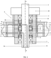
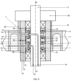
- a rotating joint to allow pressurized air to be fed, through a hub 1, from a rotation pin 2 with respect to an axis XX on bearings 3 to a tire 4 on a rim 5, comprises a distribution spool 6 to prevent the passage of pressurized air through the bearings 3.
- the distribution spool 6 comprises at least one valve 7, 8, against a respective disc with a first shoulder 9, and a disc with a second shoulder 10.
- At least one guiding device consisting of at least one protruding tooth 11, 12 able to slide with respect to a grooved support 13, 14, prevents rotation of the valve 7, 8 with respect to the rotation pin 2.
- the valve 7, 8 slides freely along a direction parallel to the X-X axis.
- This at least one protruding tooth 11, 12 is integral with the valve 7, 8, while the grooved support 13, 14 is integral with a ring 15, 16.
- the ring 15, 16 is keyed or one piece with respect to the rotation pin 2.
- the respective disk with a first shoulder 9, disk with a second shoulder 10, coaxial to the valve 7, 8 comprises at least one sealing ring 17 keyed onto a shaped seat of an outer circular edge of the respective first shoulder 9, second shoulder 10.
- Such at least one sealing ring 17 presses radially on the internal surface of the hub 1.
- valve 7, 8 comprises at least one sealing ring 26 keyed onto a shaped seat of an internal circular edge of the valve 7, 8.
- the hub 1 comprises a breather channel 27 positioned at the height of this at least one sealing ring 17.
- the breather channel 27 is adapted to connect the internal surface of the hub 1 with a pneumatic non-return valve 28 positioned on the external surface of the hub 1, to allow the sliding of the valve 7, 8.
- the pressurized air is fed through a first channel 18, with the valve 7 against the disc with a first shoulder 9, to allow pressurized air to be fed through a tank 20 of repair material carried by the pressurized air.
- pressurized air is fed through a second channel 19, with the valve 8 against the disc with a second shoulder 10, to allow pressurized air to be fed through a tank 20 of repair material transported by pressurized air.
- An electronic control unit 21 allows to selectively feed air under pressure through the first channel 18 and the second channel 19.
- the tank 20 is arranged on the hub 1.
- the tank 20 is detached from the hub 1 and made inside the rim 5.
- the tank 20 is refillable. Alternatively, the tank 20 can be replaced by means of a cartridge.
- such at least one valve 7, 8 is detached from the respective disc with a first shoulder 9, and the disc with a second shoulder 10, by means of supplying pressurized air 24, 25, connected with the respective first channel 18 and second channel 19.
- the respective disk with a first shoulder 9, and the disk with a second shoulder 10 comprises a rotating seal to ensure the sealing of the air under pressure between the respective disk with a first shoulder 9, a disk with a second shoulder 10 and the rotation pin 2.
- the rotating seal adhering to a temperature sensor connected to the electronic control unit 21 allows to selectively supply pressurized air through the first channel 18 and the second channel 19, continuously or intermittently, depending on the temperature detected and the instantaneous rotation speed measured.
- valve 7, 8 slides freely along a direction parallel to the XX axis, guaranteeing pressure tightness as inside it, on the XX axis side, sealing rings 26 are inserted in order to guarantee a perfect tightness to the pressurized air and totally preserve the valve 7, 8, from wear due to sanding.
- the O-ring is designed as a floating O-ring.
- the O-ring is not rubber, but a rigid and lubricating plastic is produced.
- the O-ring is brought to its inner diameter with a conical surface, which is preferably a part of the inner ring wall in contact.
- the groove of the O-ring is significantly greater than the thickness of the O-ring in both width and height.
- the O-ring preferably has a diameter of about 3 mm.
- the O-ring can move in a buoyant relationship with the O-ring groove positioned both axially and radially and is applied when pressure is applied to the outward facing seal from the pressure side wall of the O-ring groove, which is preferably a part of the outer ring.
- the process is not temporarily free of losses, which does not affect the function of the rotating union.
- the inner ring having the tapered surface towards the side wall of the O-ring groove has an angle of inclination with respect to the axis of rotation of the rotating union of at least 10°.
- the object of the present invention is an evolution of the device described in document IT201700092610 .
- the rotating joint comes into operation by moving the valves towards the ends and in contact with the shoulders.
- the contact between the two elements causes the valves to rotate on the pivot pin, causing wear over time due to smoothing inside the valves.
- Two channels 18, 19 are formed in the rotation pin of the wheel, with separate and independent inputs, in order to perform two distinct roles: tire inflation only; tire inflation and repair.
- pressurized air is sent through the two channels 18, 19, selectively.
- the pressurized air is contained in a tank which is kept charged by a portable mini compressor even if low pressures such as those available at the outlet of the portable mini compressors on the market are required, both the tank and any mini compressor installed on board the vehicle.
- the transmission of information and/or signals on the condition of the tire are brought to a control unit with wireless transmission systems through sensors installed on the valves of the tire itself, the data on the condition of the tire are visible to the driver by means of a screen mounted on the vehicle.
- the activation and deactivation of the inflation and repair functions takes place by means of an electronic system entirely mounted on the vehicle which does not require any electrical contact with the device, rotating joint, thus eliminating all the sliding electrical contacts and the relative rotating means.
- the system can be activated automatically by the electronic control unit or in second case manually by the driver.
- the first channel 18 passes through the rotation pin, up to approximately one third of the length of the rotation pin, the pressurized air introduced into the first channel 18 enters the portion of the distribution box delimited by the first two shoulders 9.
- the pressurized air it pushes the valve 7 against the two first shoulders 9 with consequent output of the low pressure air from the channels 27 and from the pneumatic non-return valves 28. In this way, the movement of the valve 7 takes place without any kind of disturbance.
- the pressurized air enters the tire through a channel 31 equipped with a safety valve.
- Identical valve structure is provided for the second channel, always made inside the rotation pin, on the same side of the first channel, or alternatively, on the opposite side with respect to the first channel through the rotation pin up to about two thirds of the length of the rotation pin.
- the pressurized air introduced into the second channel 19 enters the portion of the distribution box delimited by the two second shoulders 10, the valve 8 striking against the two second shoulders allows the introduction of pressurized air into the tank containing the repair liquid through a channel 29 equipped with safety valve.
- a second channel 30 equipped with a safety valve that allows the injection of repair liquid and pressurized air inside the tire to allow the repair and inflation of the tire.
- pressurized air enters the tank causing the sealing product to escape from an additional channel downstream of the tank, bringing the pressurized air/repair product mixture to an additional valve on the tire.
- the tank was built in a first draft of the project around the hub but it is also possible to build it inside the rim.
Landscapes
- Engineering & Computer Science (AREA)
- Mechanical Engineering (AREA)
Claims (10)
- Drehgelenk, um die Zuführung von Druckluft über eine Nabe (1) von einem Drehzapfen (2) bezüglich einer Achse (XX) auf Lagern (3) zu einem Reifen (4) auf einer Felge zu ermöglichen ( 5), umfassend eine Verteilerschublade (6), um den Durchgang von Druckluft durch die Lager (3) zu verhindern, wobei die Verteilerschublade (6) mindestens ein Ventil (7, 8) aufweist, das an einer jeweiligen Scheibe mit einer ersten Schulter ( 9) oder eine Diskette mit eine zweite Schulter (10), dadurch gekennzeichnet, dass das Drehgelenk mindestens eine Führungsvorrichtung umfasst, die aus mindestens einem hervorstehenden Zahn (11, 12) besteht, der in Bezug auf einen gerillten Träger (13, 14) gleiten kann, um eine Drehung des Gelenks zu verhindern Ventil (7, 8) in Bezug auf den Drehstift (2), wobei das Ventil (7, 8) frei entlang einer Richtung parallel zu der Achse (XX) gleitet.
- Drehgelenk nach dem vorhergehenden Anspruch, dadurch gekennzeichnet, dass der mindestens eine vorstehende Zahn (11, 12) fest mit dem Ventil (7, 8) verbunden ist, während der gerillte Träger (13, 14) fest mit einem Ring (15, 16), wobei der Ring (15, 16) mit dem Drehstift (2) verkeilt oder fest verbunden ist.
- Drehgelenk nach Anspruch 1, dadurch gekennzeichnet, dass die jeweilige Scheibe mit einem ersten Absatz (9) bzw. Scheibe mit einem zweiten Absatz (10) koaxial zum Ventil (7, 8) mindestens einen Dichtring (17) aufweist, auf einen geformten Sitz einer äußeren kreisförmigen Kante der jeweiligen Scheibe mit einer ersten Schulter (9) oder Scheibe mit einer zweiten Schulter (10) aufgekeilt ist, wobei der mindestens eine Dichtungsring (17) radial auf die Innenfläche der Scheibe drückt Nabe (1).
- Drehgelenk nach einem der vorhergehenden Ansprüche, dadurch gekennzeichnet, dass das Ventil (7, 8) mindestens einen Dichtring (26) aufweist, der auf einem Formsitz einer inneren kreisförmigen Kante des Ventils (7, 8) aufgekeilt ist. Zumindest ein Dichtring (26) drückt radial auf die Oberfläche des Drehzapfens (2).
- Drehgelenk nach Anspruch 3, dadurch gekennzeichnet, dass die Nabe (1) einen Entlüftungskanal (27) aufweist, der auf der Höhe des mindestens einen Dichtrings (17) positioniert ist, wobei der Entlüftungskanal (27) zur Verbindung mit dem Inneren geeignet ist Oberfläche der Nabe (1) mit einem pneumatischen Rückschlagventil (28), das auf der Außenfläche der Nabe (1) positioniert ist.
- Drehgelenk nach einem der vorhergehenden Ansprüche, dadurch gekennzeichnet, dass es eine elektronische Steuereinheit (21) umfasst, um eine selektive Zufuhr von Druckluft durch einen ersten Kanal (18) und einen zweiten Kanal (19) zu ermöglichen einen Tank (20) mit Reparaturmaterial, das durch die Druckluft transportiert wird, wobei der erste Kanal (18) mit dem Ventil (7) mit einer ersten Schulter (9) an der Scheibe anliegt und der zweite Kanal (19) mit dem Ventil (8) mit einer zweiten Schulter gegen die Scheibe (10).
- Drehgelenk nach Anspruch 6, dadurch gekennzeichnet, dass der Tank (20) an der Nabe (1) angeordnet oder von der Nabe (1) gelöst innerhalb der Felge (5) ausgebildet ist, und dass der Der Tank (20) ist nachfüllbar oder durch eine Kartusche austauschbar.
- Drehgelenk nach einem der vorhergehenden Ansprüche, dadurch gekennzeichnet, dass das mindestens eine Ventil (7, 8) von der jeweiligen Scheibe mit einer ersten Schulter (9) bzw. Scheibe mit einer zweiten Schulter (10) gelöst ist Mittel zur Rückfederung (22, 23).
- Drehgelenk nach Anspruch 6, dadurch gekennzeichnet, dass das mindestens eine Ventil (7, 8) von der jeweiligen Scheibe mit erstem Absatz (9) bzw. Scheibe mit zweitem Absatz (10) gelöst ist Zuführen der Druckluft (24, 25), wobei die versorgungseinrichtung des Drucklufts (24, 25) mit dem jeweiligen ersten Kanal (18) und dem zweiten Kanal (19) verbunden ist.
- Drehgelenk nach Anspruch 3, dadurch gekennzeichnet, dass die jeweilige Scheibe mit einer ersten Schulter (9) oder Scheibe mit einer zweiten Schulter (10) ein rotierendes Dichtelement aufweist, um die Abdichtung der Druckluft zwischen der jeweiligen Scheibe zu gewährleisten mit einer ersten Schulter (9), oder Scheibe mit einer zweiten Schulter (10) und dem Rotationsstift (2), wobei das rotierende Dichtelement das Anhaften an einem mit der elektronischen Steuereinheit (21) verbundenen Temperatursensor ermöglicht selektiv Druckluft durch den ersten Kanal (18) und den zweiten Kanal (19) kontinuierlich oder intermittierend zuzuführen, abhängig von der erfassten Temperatur und der gemessenen momentanen Drehzahl.
Applications Claiming Priority (1)
| Application Number | Priority Date | Filing Date | Title |
|---|---|---|---|
| PCT/IT2020/000087 WO2022130423A1 (en) | 2020-12-18 | 2020-12-18 | Rotating joint |
Publications (2)
| Publication Number | Publication Date |
|---|---|
| EP4263243A1 EP4263243A1 (de) | 2023-10-25 |
| EP4263243B1 true EP4263243B1 (de) | 2025-04-16 |
Family
ID=74556957
Family Applications (1)
| Application Number | Title | Priority Date | Filing Date |
|---|---|---|---|
| EP20851301.0A Active EP4263243B1 (de) | 2020-12-18 | 2020-12-18 | Drehdurchführung |
Country Status (2)
| Country | Link |
|---|---|
| EP (1) | EP4263243B1 (de) |
| WO (1) | WO2022130423A1 (de) |
Families Citing this family (2)
| Publication number | Priority date | Publication date | Assignee | Title |
|---|---|---|---|---|
| US11897295B2 (en) * | 2020-10-09 | 2024-02-13 | Cnh Industrial America Llc | Axle assembly having a tire inflation system |
| DE102023210052A1 (de) * | 2023-10-13 | 2025-04-17 | Contitech Deutschland Gmbh | Kleinfahrzeug, vorzugsweise Lastenrad, mit Luftreifen |
Family Cites Families (7)
| Publication number | Priority date | Publication date | Assignee | Title |
|---|---|---|---|---|
| US4804027A (en) | 1987-09-17 | 1989-02-14 | Eaton Corporation | Axle and wheel assembly |
| JP2009056948A (ja) | 2007-08-31 | 2009-03-19 | Toyota Motor Corp | 空気圧調整システム |
| WO2014063873A2 (de) | 2012-10-26 | 2014-05-01 | Gv Engineering Gmbh | Fahrzeugachsbaugruppe mit integrierter druckmittelleitung zur reifenbefüllung |
| DE102013105890A1 (de) | 2013-06-07 | 2014-12-11 | Claas Selbstfahrende Erntemaschinen Gmbh | Drehdurchführung |
| DE102015013693B3 (de) | 2015-10-22 | 2016-12-01 | Erich Schürmann | Drehdurchführung mit schwimmenden, selbsanlegenden O-Ringen |
| IT201700085893A1 (it) | 2017-07-27 | 2019-01-27 | Trelleborg Wheel Sys Italia Spa | Collettore rotante e sistema di regolazione della pressione di pneumatici. |
| IT201700092610A1 (it) | 2017-08-10 | 2019-02-10 | Cerreti Vanessa | Dispositivo per il gonfiaggio e/o la riparazione di uno pneumatico durante la marcia del veicolo. |
-
2020
- 2020-12-18 EP EP20851301.0A patent/EP4263243B1/de active Active
- 2020-12-18 WO PCT/IT2020/000087 patent/WO2022130423A1/en not_active Ceased
Also Published As
| Publication number | Publication date |
|---|---|
| WO2022130423A1 (en) | 2022-06-23 |
| EP4263243A1 (de) | 2023-10-25 |
Similar Documents
| Publication | Publication Date | Title |
|---|---|---|
| EP4263243B1 (de) | Drehdurchführung | |
| AU2019204131B2 (en) | Rotary union for automatic tire inflation system | |
| EP0142236B1 (de) | Sicherheitsdichtungsvorrichtung für Wellen, die durch Verformung des Dichtungsringes entsteht | |
| US5979526A (en) | Hub and hub-holder assembly for vehicles equipped with a central tire inflation system | |
| US3637222A (en) | Seals | |
| EP0308256A2 (de) | Achs- und Radeinheit | |
| EP0063959B1 (de) | Abdichtungen | |
| US20170122435A1 (en) | Sealing arrangement | |
| KR102483039B1 (ko) | 비드형의 실린더형 캠을 포함하는 압축기 조립체 | |
| KR20190126284A (ko) | 방사형 피스톤을 포함하는 압축기 어셈블리 | |
| US10054231B2 (en) | Operable seal connector device | |
| EP3966046B1 (de) | Drehübertragungsvorrichtung zur übertragung von steuer- und/oder arbeitsdrücken auf einen fluidkanal im inneren einer welle | |
| US2752175A (en) | Shaft seal | |
| US8327895B2 (en) | Drive axle seal body and tire inflation system | |
| CN109890630A (zh) | 用于轮胎充气系统的旋转接头组件 | |
| US7051777B2 (en) | Pressure transmitting axle assembly | |
| IT201900018323A1 (it) | Giunto rotante | |
| JP2920005B2 (ja) | 機械的面シール | |
| CN221113380U (zh) | 轮胎充气系统 | |
| EP3321110B1 (de) | System zur änderung des reifendrucks | |
| CN210890107U (zh) | 内带轴向浮动托盘套的液体用机械密封 | |
| US10556470B2 (en) | Rotary joint assembly for a tire pressure management system | |
| JP2000130605A (ja) | 軸封装置 | |
| WO2014098738A1 (en) | Sealing arrangement | |
| JPH02169310A (ja) | タイヤ圧調整装置 |
Legal Events
| Date | Code | Title | Description |
|---|---|---|---|
| STAA | Information on the status of an ep patent application or granted ep patent |
Free format text: STATUS: UNKNOWN |
|
| STAA | Information on the status of an ep patent application or granted ep patent |
Free format text: STATUS: THE INTERNATIONAL PUBLICATION HAS BEEN MADE |
|
| PUAI | Public reference made under article 153(3) epc to a published international application that has entered the european phase |
Free format text: ORIGINAL CODE: 0009012 |
|
| STAA | Information on the status of an ep patent application or granted ep patent |
Free format text: STATUS: REQUEST FOR EXAMINATION WAS MADE |
|
| 17P | Request for examination filed |
Effective date: 20230705 |
|
| AK | Designated contracting states |
Kind code of ref document: A1 Designated state(s): AL AT BE BG CH CY CZ DE DK EE ES FI FR GB GR HR HU IE IS IT LI LT LU LV MC MK MT NL NO PL PT RO RS SE SI SK SM TR |
|
| DAV | Request for validation of the european patent (deleted) | ||
| DAX | Request for extension of the european patent (deleted) | ||
| GRAP | Despatch of communication of intention to grant a patent |
Free format text: ORIGINAL CODE: EPIDOSNIGR1 |
|
| STAA | Information on the status of an ep patent application or granted ep patent |
Free format text: STATUS: GRANT OF PATENT IS INTENDED |
|
| RIC1 | Information provided on ipc code assigned before grant |
Ipc: B29L 30/00 20060101ALN20241108BHEP Ipc: B29C 73/16 20060101ALI20241108BHEP Ipc: B60C 23/00 20060101AFI20241108BHEP |
|
| INTG | Intention to grant announced |
Effective date: 20241211 |
|
| GRAS | Grant fee paid |
Free format text: ORIGINAL CODE: EPIDOSNIGR3 |
|
| GRAA | (expected) grant |
Free format text: ORIGINAL CODE: 0009210 |
|
| STAA | Information on the status of an ep patent application or granted ep patent |
Free format text: STATUS: THE PATENT HAS BEEN GRANTED |
|
| AK | Designated contracting states |
Kind code of ref document: B1 Designated state(s): AL AT BE BG CH CY CZ DE DK EE ES FI FR GB GR HR HU IE IS IT LI LT LU LV MC MK MT NL NO PL PT RO RS SE SI SK SM TR |
|
| REG | Reference to a national code |
Ref country code: GB Ref legal event code: FG4D |
|
| REG | Reference to a national code |
Ref country code: CH Ref legal event code: EP |
|
| REG | Reference to a national code |
Ref country code: IE Ref legal event code: FG4D |
|
| REG | Reference to a national code |
Ref country code: DE Ref legal event code: R096 Ref document number: 602020049682 Country of ref document: DE |
|
| REG | Reference to a national code |
Ref country code: NL Ref legal event code: MP Effective date: 20250416 |
|
| PG25 | Lapsed in a contracting state [announced via postgrant information from national office to epo] |
Ref country code: NL Free format text: LAPSE BECAUSE OF FAILURE TO SUBMIT A TRANSLATION OF THE DESCRIPTION OR TO PAY THE FEE WITHIN THE PRESCRIBED TIME-LIMIT Effective date: 20250416 |
|
| REG | Reference to a national code |
Ref country code: AT Ref legal event code: MK05 Ref document number: 1785366 Country of ref document: AT Kind code of ref document: T Effective date: 20250416 |
|
| PG25 | Lapsed in a contracting state [announced via postgrant information from national office to epo] |
Ref country code: PT Free format text: LAPSE BECAUSE OF FAILURE TO SUBMIT A TRANSLATION OF THE DESCRIPTION OR TO PAY THE FEE WITHIN THE PRESCRIBED TIME-LIMIT Effective date: 20250818 Ref country code: ES Free format text: LAPSE BECAUSE OF FAILURE TO SUBMIT A TRANSLATION OF THE DESCRIPTION OR TO PAY THE FEE WITHIN THE PRESCRIBED TIME-LIMIT Effective date: 20250416 Ref country code: FI Free format text: LAPSE BECAUSE OF FAILURE TO SUBMIT A TRANSLATION OF THE DESCRIPTION OR TO PAY THE FEE WITHIN THE PRESCRIBED TIME-LIMIT Effective date: 20250416 |
|
| REG | Reference to a national code |
Ref country code: LT Ref legal event code: MG9D |
|
| PG25 | Lapsed in a contracting state [announced via postgrant information from national office to epo] |
Ref country code: GR Free format text: LAPSE BECAUSE OF FAILURE TO SUBMIT A TRANSLATION OF THE DESCRIPTION OR TO PAY THE FEE WITHIN THE PRESCRIBED TIME-LIMIT Effective date: 20250717 Ref country code: NO Free format text: LAPSE BECAUSE OF FAILURE TO SUBMIT A TRANSLATION OF THE DESCRIPTION OR TO PAY THE FEE WITHIN THE PRESCRIBED TIME-LIMIT Effective date: 20250716 |
|
| PG25 | Lapsed in a contracting state [announced via postgrant information from national office to epo] |
Ref country code: PL Free format text: LAPSE BECAUSE OF FAILURE TO SUBMIT A TRANSLATION OF THE DESCRIPTION OR TO PAY THE FEE WITHIN THE PRESCRIBED TIME-LIMIT Effective date: 20250416 |
|
| PG25 | Lapsed in a contracting state [announced via postgrant information from national office to epo] |
Ref country code: BG Free format text: LAPSE BECAUSE OF FAILURE TO SUBMIT A TRANSLATION OF THE DESCRIPTION OR TO PAY THE FEE WITHIN THE PRESCRIBED TIME-LIMIT Effective date: 20250416 |
|
| PG25 | Lapsed in a contracting state [announced via postgrant information from national office to epo] |
Ref country code: HR Free format text: LAPSE BECAUSE OF FAILURE TO SUBMIT A TRANSLATION OF THE DESCRIPTION OR TO PAY THE FEE WITHIN THE PRESCRIBED TIME-LIMIT Effective date: 20250416 |
|
| PG25 | Lapsed in a contracting state [announced via postgrant information from national office to epo] |
Ref country code: AT Free format text: LAPSE BECAUSE OF FAILURE TO SUBMIT A TRANSLATION OF THE DESCRIPTION OR TO PAY THE FEE WITHIN THE PRESCRIBED TIME-LIMIT Effective date: 20250416 |
|
| PG25 | Lapsed in a contracting state [announced via postgrant information from national office to epo] |
Ref country code: RS Free format text: LAPSE BECAUSE OF FAILURE TO SUBMIT A TRANSLATION OF THE DESCRIPTION OR TO PAY THE FEE WITHIN THE PRESCRIBED TIME-LIMIT Effective date: 20250716 |
|
| PG25 | Lapsed in a contracting state [announced via postgrant information from national office to epo] |
Ref country code: IS Free format text: LAPSE BECAUSE OF FAILURE TO SUBMIT A TRANSLATION OF THE DESCRIPTION OR TO PAY THE FEE WITHIN THE PRESCRIBED TIME-LIMIT Effective date: 20250816 |
|
| PG25 | Lapsed in a contracting state [announced via postgrant information from national office to epo] |
Ref country code: LV Free format text: LAPSE BECAUSE OF FAILURE TO SUBMIT A TRANSLATION OF THE DESCRIPTION OR TO PAY THE FEE WITHIN THE PRESCRIBED TIME-LIMIT Effective date: 20250416 |
|
| PG25 | Lapsed in a contracting state [announced via postgrant information from national office to epo] |
Ref country code: SM Free format text: LAPSE BECAUSE OF FAILURE TO SUBMIT A TRANSLATION OF THE DESCRIPTION OR TO PAY THE FEE WITHIN THE PRESCRIBED TIME-LIMIT Effective date: 20250416 Ref country code: DK Free format text: LAPSE BECAUSE OF FAILURE TO SUBMIT A TRANSLATION OF THE DESCRIPTION OR TO PAY THE FEE WITHIN THE PRESCRIBED TIME-LIMIT Effective date: 20250416 |
|
| PG25 | Lapsed in a contracting state [announced via postgrant information from national office to epo] |
Ref country code: CZ Free format text: LAPSE BECAUSE OF FAILURE TO SUBMIT A TRANSLATION OF THE DESCRIPTION OR TO PAY THE FEE WITHIN THE PRESCRIBED TIME-LIMIT Effective date: 20250416 |
|
| PG25 | Lapsed in a contracting state [announced via postgrant information from national office to epo] |
Ref country code: EE Free format text: LAPSE BECAUSE OF FAILURE TO SUBMIT A TRANSLATION OF THE DESCRIPTION OR TO PAY THE FEE WITHIN THE PRESCRIBED TIME-LIMIT Effective date: 20250416 |
|
| PG25 | Lapsed in a contracting state [announced via postgrant information from national office to epo] |
Ref country code: SK Free format text: LAPSE BECAUSE OF FAILURE TO SUBMIT A TRANSLATION OF THE DESCRIPTION OR TO PAY THE FEE WITHIN THE PRESCRIBED TIME-LIMIT Effective date: 20250416 |