EP4258934B1 - Verpackungsvorrichtung für kosmetische produkte - Google Patents
Verpackungsvorrichtung für kosmetische produkte Download PDFInfo
- Publication number
- EP4258934B1 EP4258934B1 EP21835665.7A EP21835665A EP4258934B1 EP 4258934 B1 EP4258934 B1 EP 4258934B1 EP 21835665 A EP21835665 A EP 21835665A EP 4258934 B1 EP4258934 B1 EP 4258934B1
- Authority
- EP
- European Patent Office
- Prior art keywords
- lid
- stiffening
- stiffening member
- receptacle
- ribs
- Prior art date
- Legal status (The legal status is an assumption and is not a legal conclusion. Google has not performed a legal analysis and makes no representation as to the accuracy of the status listed.)
- Active
Links
Images



Classifications
-
- A—HUMAN NECESSITIES
- A45—HAND OR TRAVELLING ARTICLES
- A45D—HAIRDRESSING OR SHAVING EQUIPMENT; EQUIPMENT FOR COSMETICS OR COSMETIC TREATMENTS, e.g. FOR MANICURING OR PEDICURING
- A45D40/00—Casings or accessories specially adapted for storing or handling solid or pasty toiletry or cosmetic substances, e.g. shaving soaps or lipsticks
- A45D40/22—Casings characterised by a hinged cover
-
- A—HUMAN NECESSITIES
- A45—HAND OR TRAVELLING ARTICLES
- A45D—HAIRDRESSING OR SHAVING EQUIPMENT; EQUIPMENT FOR COSMETICS OR COSMETIC TREATMENTS, e.g. FOR MANICURING OR PEDICURING
- A45D33/00—Containers or accessories specially adapted for handling powdery toiletry or cosmetic substances
- A45D33/006—Vanity boxes or cases, compacts, i.e. containing a powder receptacle and a puff or applicator
- A45D33/008—Vanity boxes or cases, compacts, i.e. containing a powder receptacle and a puff or applicator comprising a mirror
-
- A—HUMAN NECESSITIES
- A45—HAND OR TRAVELLING ARTICLES
- A45D—HAIRDRESSING OR SHAVING EQUIPMENT; EQUIPMENT FOR COSMETICS OR COSMETIC TREATMENTS, e.g. FOR MANICURING OR PEDICURING
- A45D40/00—Casings or accessories specially adapted for storing or handling solid or pasty toiletry or cosmetic substances, e.g. shaving soaps or lipsticks
- A45D40/24—Casings for two or more cosmetics
-
- A—HUMAN NECESSITIES
- A45—HAND OR TRAVELLING ARTICLES
- A45D—HAIRDRESSING OR SHAVING EQUIPMENT; EQUIPMENT FOR COSMETICS OR COSMETIC TREATMENTS, e.g. FOR MANICURING OR PEDICURING
- A45D2200/00—Details not otherwise provided for in A45D
- A45D2200/05—Details of containers
-
- B—PERFORMING OPERATIONS; TRANSPORTING
- B65—CONVEYING; PACKING; STORING; HANDLING THIN OR FILAMENTARY MATERIAL
- B65D—CONTAINERS FOR STORAGE OR TRANSPORT OF ARTICLES OR MATERIALS, e.g. BAGS, BARRELS, BOTTLES, BOXES, CANS, CARTONS, CRATES, DRUMS, JARS, TANKS, HOPPERS, FORWARDING CONTAINERS; ACCESSORIES, CLOSURES, OR FITTINGS THEREFOR; PACKAGING ELEMENTS; PACKAGES
- B65D2543/00—Lids or covers essentially for box-like containers
- B65D2543/00009—Details of lids or covers for rigid or semi-rigid containers
- B65D2543/00018—Overall construction of the lid
- B65D2543/00231—Overall construction of the lid made of several pieces
-
- B—PERFORMING OPERATIONS; TRANSPORTING
- B65—CONVEYING; PACKING; STORING; HANDLING THIN OR FILAMENTARY MATERIAL
- B65D—CONTAINERS FOR STORAGE OR TRANSPORT OF ARTICLES OR MATERIALS, e.g. BAGS, BARRELS, BOTTLES, BOXES, CANS, CARTONS, CRATES, DRUMS, JARS, TANKS, HOPPERS, FORWARDING CONTAINERS; ACCESSORIES, CLOSURES, OR FITTINGS THEREFOR; PACKAGING ELEMENTS; PACKAGES
- B65D2543/00—Lids or covers essentially for box-like containers
- B65D2543/00009—Details of lids or covers for rigid or semi-rigid containers
- B65D2543/00342—Central part of the lid
- B65D2543/00398—Reinforcing ribs in the central part of the closure
Definitions
- the present invention relates to the field of the packaging of cosmetic products.
- cosmetic product is understood, notably within the meaning of the present invention, to mean a product as defined in Regulation (EC) No 1223/2009 of the European Parliament and of the Council of 30 November 2009 relating to cosmetic products.
- the packaging device is intended for packaging a cosmetic product, such as a make-up product, for example an anhydrous make-up product, in the form of a compact powder, or a non-anhydrous formulation, for example a hot-pour formulation, intended to be applied, for example, to the user's epidermis, such as a foundation or a face powder.
- a cosmetic product such as a make-up product, for example an anhydrous make-up product, in the form of a compact powder, or a non-anhydrous formulation, for example a hot-pour formulation, intended to be applied, for example, to the user's epidermis, such as a foundation or a face powder.
- Such a cosmetic product packaging device may, for example, be in the form of a case comprising a receptacle delimiting an internal cavity, and a lid that is hinged to said receptacle between a position closing said case, in which it cooperates with the receptacle to close the internal cavity, and a position opening the case, in which it is spaced apart from the receptacle to free up access to the internal cavity.
- Document US2014061198 discloses a device for packaging a product comprising a receptacle, a lid hinged to the receptacle, and a stiffening member mounted in the lid and comprising a stiffening element compromising a plurality of ribs extending along the elevation axis from the stiffening member towards the lid.
- making cosmetic product packaging devices lighter is an essential concern during the design thereof, both in order to reduce the amount of material, in particular plastics material, used to make the device, thereby reducing its manufacturing cost, but also the resources and energy necessary for the manufacture, transport and recyclability thereof, thereby also responding to an issue of reducing the ecological impact thereof during the lifetime thereof.
- a subject of the invention is a device for packaging a product, in particular a cosmetic product, comprising:
- the device comprises a stiffening member mounted in the lid.
- One of the stiffening member or the lid comprises at least one stiffening element that extends along the elevation axis from one of the stiffening member or the lid towards the other of the lid or the stiffening member and is rigidly secured to the other of the lid or the stiffening member.
- the stiffening member may comprise the stiffening element extending towards the lid, or the lid may comprise the stiffening element extending towards the stiffening member.
- stiffening member By virtue of the stiffening member, it is possible to significantly reduce the thicknesses, in particular of the lid, and thus the weight and the amount of material used to make the product packaging device, while maintaining constant stiffness of the assembly formed by the lid and the stiffening member.
- the lid and/or the stiffening member is/are made of plastic, in particular a thermoplastic polymer.
- the lid and/or the stiffening member is/are made of a polyolefin, for example polypropylene (PP), polyethylene (PE), high or low density polyethylene (HDPE, LDPE), or linear low density polyethylene (LLDPE).
- PP polypropylene
- PE polyethylene
- HDPE high or low density polyethylene
- LLDPE linear low density polyethylene
- the lid and/or the stiffening member may also be made of polyethylene terephthalate (PET) or another copolyester, or even a thermoplastic polymer with good impact resistance, such as acrylonitrile butadiene styrene (ABS) or styrene acrylonitrile (SAN) copolymer or another styrene polymer.
- PET polyethylene terephthalate
- ABS acrylonitrile butadiene styrene
- SAN styrene acrylonitrile
- the lid and/or the stiffening member is/are made of a polymer selected from the group comprising polyolefins, polyesters or styrene polymers.
- the lid and the stiffening member are made of a polyolefin, for example, there is a considerable weight saving for the lid/stiffening member assembly.
- the density of polypropylene is 0.9 whereas the density of a thermoplastic polymer such as acrylonitrile butadiene styrene (ABS) is 1.05.
- the weight of the lid/stiffening member assembly is lower.
- the weight saving observed is between 15% and 50% compared with a packaging device that does not have a stiffening member in the lid.
- thermoplastics in particular polyolefins, copolyesters such as polyethylene terephthalate (PET) or styrene polymers such as acrylonitrile butadiene styrene (ABS) or styrene acrylonitrile (SAN) copolymer are highly recyclable and their use thus meets environmental requirements.
- PET polyethylene terephthalate
- ABS acrylonitrile butadiene styrene
- SAN styrene acrylonitrile
- the lid and/or the stiffening member may thus be made of recycled polyolefins, recycled copolyesters such as polyethylene terephthalate (PET) or recycled styrene polymers such as acrylonitrile butadiene styrene (ABS) or styrene acrylonitrile (SAN) copolymer.
- recycled polyolefins recycled copolyesters such as polyethylene terephthalate (PET) or recycled styrene polymers such as acrylonitrile butadiene styrene (ABS) or styrene acrylonitrile (SAN) copolymer.
- the lid and the stiffening member are advantageously made of the same material so that they can be recycled together.
- the stiffening element comprises a network of ribs or stiffening protrusions comprising at least one plurality of ribs extending along the elevation axis from one of the stiffening member or the lid towards the other of the lid or the stiffening member.
- the ribs of the network of ribs are advantageously connected to one another.
- the stiffening member comprises a base in which the stiffening element extends along the elevation axis from an upper surface of the base towards a lower surface of an upper wall of the lid.
- the stiffening element is made as one piece with the base of the stiffening member.
- the stiffening element and the base of the stiffening member form a single piece formed from a single material during a single moulding operation.
- the stiffening element is mechanically secured to the lid, for example by ultrasonic welding.
- each of the ribs of the network of stiffening ribs is mechanically secured or rigidly secured to the lower surface of the upper wall of the lid, for example by ultrasonic welding.
- any other securing means could be provided, such as adhesive bonding or laser welding, for example.
- the stiffening element is made as one piece with the lid.
- the lower end of each of the ribs of the network of stiffening ribs is mechanically secured or rigidly secured to the upper surface of the base of the stiffening member, for example by ultrasonic welding.
- the network of stiffening ribs forms a mesh comprising a plurality of contiguous shapes.
- the mesh comprises a plurality of contiguous polygonal shapes.
- the mesh is advantageously symmetrical with respect to a median plan passing through the centre of the stiffening member.
- the mesh may be a grid comprising a plurality of contiguous quadrilaterals, for example rectangles, squares or any other four-sided polygon.
- grid means a set of two families of horizontal and vertical lines in one plane.
- the grid comprises a first group of substantially identical quadrilaterals and a second group of quadrilaterals arranged on each side of the first group, the quadrilaterals of the second group having different dimensions.
- the grid is advantageously symmetrical with respect to a median plan passing through the centre of the stiffening member.
- the mesh comprises a plurality of contiguous hexagons, for example in a honeycomb arrangement.
- the network of stiffening ribs comprises a central protrusion and a plurality of radial protrusions extending radially outwards from the central protrusion.
- the central protrusion has, for example, a closed or non-closed contour.
- the radial protrusions are spaced apart regularly around the central protrusion.
- the number of radial protrusions may be greater than or equal to four.
- the radial protrusions may extend from the central protrusion as far as the contour of the base.
- the radial protrusions could extend radially over part of the base.
- the radial protrusions extend radially between the central protrusion and the contour of the base while being connected to the central protrusion.
- Such a configuration may in particular be advantageous when the stiffening member is secured to the lid by adhesive bonding.
- a space could be provided in the radial direction between each end of the radial protrusions and the central protrusion.
- Such a configuration may in particular be advantageous when the stiffening member is secured to the lid by ultrasonic welding, erratic behaviour of the material being liable to occur at the junction between the radial protrusions and the central protrusion during such a process if these were connected together.
- the central protrusion and/or one or more radial protrusions could likewise be made for the central protrusion and/or one or more radial protrusions to form part of the lid and to extend along the elevation axis towards the stiffening member.
- the height of the stiffening element is adapted such that the outer surface of said stiffening element has a shape matching the shape of the inner surface of an upper wall of the lid.
- the height of the stiffening element increases gradually towards the centre of the stiffening element, in such a way as to form a domed outer surface following the shape of the inner surface of the upper wall of the lid.
- the device comprises a reflective surface mounted on a lower surface of the stiffening member, on the side opposite the stiffening element.
- the device comprises a support member mounted in the internal volume of the receptacle and intended to receive at least one cosmetic product.
- the internal volume of the support member is intended to receive a dish comprising at least one compartment of cosmetic product.
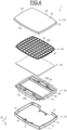
- a device 1 for packaging a product is illustrated in Figures 1 to 4 .
- a "product” means a cosmetic product such as, for example, a finely ground, compacted solid product, in the form of compact powder, that is intended to be applied, for example, to the user's epidermis.
- the compact powder may be foundation, face powder or eyeshadow that is taken up, for example, directly with the finger or with a powder puff or with a brush.
- the invention is not limited to a cosmetic product.
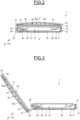
- the device 1 is for example a make-up case and comprises a receptacle 10 and a lid 20 that is hinged with respect to said receptacle 10 between a closing position, visible in Figure 2 , and an opening position, visible in Figure 3 .
- the device 1 comprises a support member 30 or dish intended to receive at least one cosmetic product.
- the device 1 not to comprise a support member 30 and for the cosmetic product to be placed directly inside the receptacle 10.
- the device 1 further comprises a stiffening member or insert 40 intended to be mounted in the lid 20 and a reflective wall 50, such as a mirror, rigidly secured to the stiffening member 40.
- the device 1 not to have a reflective wall 50.
- the receptacle 10 comprises a body with a parallelepiped overall shape extending along an elevation axis Z-Z' that is presumed to be vertical in the figures. Any other shape could be provided for the body, for example cylindrical.
- the body of the receptacle 10 comprises an internal volume 11 for receiving a cosmetic article.
- the internal volume 11 is delimited by a lower wall 12 or bottom that is substantially flat and disposed in a plane XY containing the longitudinal axis X and the transverse axis Y, two side walls 13, a front wall 14 and a rear wall 15.
- Said side walls 13, front wall 14 and rear wall 15 form a substantially square or rectangular contour.
- Other, regular or irregular, contour shapes are also possible, in particular circular, polygonal or elongate shapes.
- the lid 20 is mounted on the support member 30 by means of a hinge comprising the same axis of rotation A1, parallel to the longitudinal axis X.
- a hinge comprising the same axis of rotation A1, parallel to the longitudinal axis X.
- the lid 20 comprises an internal volume 21 delimited by an upper wall 22, two side walls 23, a front wall 24 and a rear wall 25.
- the rear wall 25 of the lid is rotatably mounted on said axis of rotation A1.
- the front wall 24 of the lid 20 may comprise a retaining member protruding in the continuation of said front wall, along the vertical axis Z in the closing position of the lid.
- the retaining member is intended to cooperate, for example by snap-fitting, with a corresponding retaining member 17 of the receptacle 10, in order to retain the lid 20 on said receptacle 10 in the closing position of said lid.
- the lid 20 is movable between a closing position, shown in Figures 1 and 2 , in which the lid 20 cooperates with the receptacle 10 and closes off access to the internal cavity 11, and an opening position, shown in Figure 3 , in which the lid 20 is pivoted away from the receptacle about the axis A1 to allow access to the internal volume 11.
- the lid 20 In the closing position, the lid 20 is disposed above the receptacle 10.
- the support member 30 is mounted in the internal cavity 11 in the receptacle 10 and is intended to receive a dish (not shown) containing the cosmetic product.
- the dish forms an insert or refill that can be removed so as to be replaced once used up or to change the cosmetic product.
- the support member 30 is secured in the receptacle 10.
- the support member 30 is separate from the receptacle 10, it is possible to use two different materials, namely a first material for the receptacle 10 and a second material for the support member 30.
- the second material is of lower quality than the material of the receptacle 10.
- the second material can have a density and thus a price lower than those of the first material, making it possible to obtain a support member that is less expensive and lighter than the receptacle 10.
- the support member 30 comprises an internal volume 31 for receiving a cosmetic product (not shown), contained in the dish.
- the internal volume 31 comprises a single compartment for receiving the dish.
- Provision could also be made for the cosmetic product(s) to be contained directly in the receptacle 10.
- the support member 30 further comprises two housings 33; 34 for receiving an accessory, for example a brush.
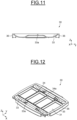
- each of the housings 33; 34 is each arranged on one side of the internal volume 31. As shown in Figures 4 and 11 , each of the housings 33; 34 comprises an extrusion or central reinforcement 33a, 34a protruding outwards from the bottom of the corresponding housing. This reinforcement is generally created during moulding, for example injection-moulding, of the material for forming the support member 30 and makes it possible to locally stiffen the support member 30.
- the support member 30 could be made to have only one housing for receiving an accessory or not to have such a housing.
- the internal volume 31 of the support member 30 is delimited by a bottom wall 35 and a peripheral wall 36 forming a closed contour.
- the stiffening member 40 is mounted in the internal cavity 21 in the lid 20 and forms a block on which the reflective surface 50, such as a mirror, may be secured.
- the stiffening member 40 is separate from the lid 10, it is possible to use two different materials, namely a first material for the lid 20 and a second material for the stiffening member 40.
- the second material is of lower quality than the material of the lid 20.
- the second material can have a density and thus a price lower than those of the first material, making it possible to obtain a stiffening member 40 that is less expensive and lighter than the lid 20.
- the stiffening member 40 comprises a substantially flat base 41 delimited axially by an upper surface 41a and a lower surface 41b.
- the stiffening member 40 further comprises a network 42 of ribs or stiffening protrusions extending along the vertical axis Z from the upper surface 41a of the base 41 towards the lower surface 22a of the upper wall 22 of the lid 20.
- each of the ribs 42a of the network 42 of stiffening ribs is mechanically secured or rigidly secured to the lower surface 22a of the upper wall 22 of the lid 20, for example by ultrasonic welding.
- the network 42 of stiffening ribs could form part of the lid 20 and could extend along the elevation axis towards the stiffening member 40.
- the lower end of each of the ribs 42a of the network 42 of stiffening ribs would be mechanically secured or rigidly secured to the upper surface 41a of the base 41 of the stiffening member 40, for example by ultrasonic welding.
- the height of the ribs 42a of the network 42 of stiffening ribs increases towards the centre of the base 41, in such a way as to form a domed outer surface 43 following the shape of the inner surface 22a of the upper wall 22 of the lid 20.
- the height of the ribs 42a of the network 42 of stiffening ribs is adapted such that the outer surface 43 of said network 42 of stiffening ribs has a shape matching the shape of the inner surface 22a of the upper wall 22 of the lid 20.
- the ribs 42a and the stiffening member 40 form a single piece formed from a single material during a single moulding operation.
- the network 42 of stiffening ribs forms a grid, i.e. an arrangement of contiguous rectangles.
- the grid comprises a plurality of contiguous quadrilaterals, for example rectangles, squares or any other four-sided polygon.
- the grid comprises a first group of substantially identical rectangles and a second group of quadrilaterals arranged on each side of said first group.
- the quadrilaterals of the second group have different dimensions.
- the grid is symmetrical with respect to a median plan passing through the centre of the stiffening member 40.
- grid means a set of two families of horizontal and vertical lines in one plane.
- the stiffening member 40' comprises a substantially flat base 41 delimited axially by an upper surface 41a and a lower surface 41b.
- the stiffening member 40' further comprises a network 42 of ribs or stiffening protrusions extending along the vertical axis Z from the upper surface 41a of the base 41 towards the lower surface 22a of the upper wall 22 of the lid 20.
- the network 42 of stiffening ribs of the stiffening member 40' further comprises a central protrusion 42a with a closed contour extending along the vertical axis Z from the upper surface 41a of the base 41 towards the lower surface 22a of the upper wall 22 of the lid 20.
- the upper end of said central protrusion 42a is mechanically secured to the lower surface 22a of the wall 22 of the lid 20, for example by ultrasonic welding.
- the network 42 of stiffening ribs could form part of the lid 20 and could extend along the elevation axis towards the stiffening member 40'.
- the lower end of the central protrusion 42a of the network 42 of stiffening ribs would be mechanically secured or rigidly secured to the upper surface 41a of the base 41 of the stiffening member 40', for example by ultrasonic welding.
- a central protrusion with a non-closed contour could be provided.
- the stiffening member 40' also comprises a plurality of radial protrusions 42b extending radially outwards from the central protrusion 42a.
- the radial protrusions 42b extend along the vertical axis Z from the upper surface 41a of the base 41 towards the lower surface 22a of the upper wall 22 of the lid 20.
- each of the radial protrusions 42b is mechanically secured to the lower surface 22a of the wall 22 of the lid 20, for example by ultrasonic welding.
- the radial protrusions 42b are spaced apart regularly around the central protrusion 42a. As a variant, a different arrangement of the radial protrusions 42b around the central protrusion 42a could be provided.
- the number of radial protrusions 42b is equal to 24.
- a different number of radial protrusions for example greater than or equal to four, could be provided.
- the radial protrusions 42b extend from the central protrusion 42a as far as the contour of the base 41.
- the radial protrusions 42b could extend radially over part of the base 41.
- the height of the radial protrusions 42 of the network 42 of stiffening ribs increases towards the central protrusion 42b arranged at the centre of the base 41, in such a way as to form a domed outer surface 43 following the shape of the inner surface 22a of the upper wall 22 of the lid 20.
- the height of the radial protrusions 42b of the network 42 of stiffening ribs is adapted such that the outer surface 43 of said network 42 of stiffening ribs has a shape matching the shape of the inner surface 22a of the upper wall 22 of the lid 20.
- the radial protrusions 42b extend radially between the central protrusion 42a and the contour of the base 41 while being connected to the central protrusion 42a.
- Such a configuration may in particular be advantageous when the stiffening member is secured to the lid by adhesive bonding.
- a space could be provided in the radial direction between each end of the radial protrusions 42b and, on the one hand, the central protrusion 42a.
- Such a configuration may in particular be advantageous when the stiffening member 40' is secured to the lid 20 by ultrasonic welding, erratic behaviour of the material being liable to occur at the junction between the radial protrusions 42b and the central protrusion 42a during such a process if these were connected together.
- the central protrusion and/or one or more radial protrusions could likewise be made for the central protrusion and/or one or more radial protrusions to form part of the lid 20 and to extend along the elevation axis towards the stiffening member 40'.
- the central protrusion 42a, the radial protrusions 42a and the stiffening member 40' form a single piece formed from a single material during a single moulding operation.
- the stiffening member 40" differs from the stiffening member 40 shown in Figures 2 to 6 only by the shape and the arrangement of the stiffening protrusions.
- the stiffening member 40" comprises a substantially flat base 41 delimited axially by an upper surface 41a and a lower surface 41b.
- the stiffening member 40" further comprises a network 42 of ribs or stiffening protrusions extending along the vertical axis Z from the upper surface 41a of the base 41 towards the lower surface 22a of the upper wall 22 of the lid 20.
- each of the ribs 42a of the network 42 of stiffening ribs is mechanically secured or rigidly secured to the lower surface 22a of the upper wall 22 of the lid 20, for example by ultrasonic welding.
- the network 42 of stiffening ribs could form part of the lid 20 and could extend along the elevation axis towards the stiffening member 40".
- the lower end of each of the ribs 42a of the network 42 of stiffening ribs would be mechanically secured or rigidly secured to the upper surface 41a of the base 41 of the stiffening member 40", for example by ultrasonic welding.
- the height of the ribs 42a of the network 42 of stiffening ribs increases towards the centre of the base 41, in such a way as to form a domed outer surface 43 following the shape of the inner surface 22a of the upper wall 22 of the lid 20.
- the height of the ribs 42a of the network 42 of stiffening ribs is adapted such that the outer surface 43 of said network 42 of stiffening ribs has a shape matching the shape of the inner surface 22a of the upper wall 22 of the lid 20.
- the ribs 42a and the stiffening member 40" form a single piece formed from a single material during a single moulding operation.
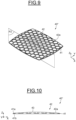
- the network 42 of stiffening ribs forms a mesh, i.e. an arrangement of contiguous shapes.
- the mesh comprises a plurality of contiguous polygonal shapes, in this case hexagons.
- an arrangement of contiguous circles could be provided.
- the polygons of the mesh are substantially identical.
- the elements of the mesh could have different dimensions.
- the mesh has a honeycomb shape.
- the mesh is symmetrical with respect to a median plan passing through the centre of the stiffening member 40".
- the invention is not limited to the shape of the protrusions of the network of stiffening ribs.
- other shapes could be provided, for example circular, polygonal, radial, protrusions with a closed contour, protrusions with an open contour, or a combination of protrusions of different shapes.
- the packaging device 1 comprises a stiffening element formed by at least one protrusion that extends along the vertical axis Z from the base of the stiffening member 40, 40', 40" towards the lower surface 22a of the upper wall 22 of the lid 20 and is mechanically secured to said surface 22a in order to form mechanical connections between said stiffening member and said lid.
- the lid 20 and/or the stiffening member 40, 40', 40" may be made of plastic, such as polyolefin, for example polypropylene (PP), high or low density polyethylene (HDPE, LDPE), or linear low density polyethylene (LLDPE).
- polyolefin for example polypropylene (PP), high or low density polyethylene (HDPE, LDPE), or linear low density polyethylene (LLDPE).
- the lid 20 and/or the stiffening member 40, 40', 40" may also be made of polyethylene terephthalate (PET) or another copolyester, or even a thermoplastic polymer such as acrylonitrile butadiene styrene (ABS) or styrene acrylonitrile (SAN) copolymer or another styrene-based material.
- PET polyethylene terephthalate
- ABS acrylonitrile butadiene styrene
- SAN styrene acrylonitrile
- the density of polypropylene is 0.9 whereas the density of a thermoplastic polymer such as acrylonitrile butadiene styrene (ABS) is 1.05.
- the weight of the lid/stiffening member assembly is lower.
- polyolefins are recyclable and their use thus meets environmental requirements.
- the lid 20 and/or the stiffening member 40, 40', 40" may thus be made of recycled polyolefins.
- the lid 20 and the stiffening member 40, 40', 40" are advantageously made of the same material so that they can be recycled together.
Landscapes
- Closures For Containers (AREA)
Claims (15)
- Vorrichtung (1) zum Verpacken eines Produkts, insbesondere eines kosmetischen Produkts, umfassend:- ein Behältnis (10), das sich entlang einer Höhenachse (Z-Z') erstreckt und ein Innenvolumen (11) umfasst;- einen Deckel (20), der in Bezug auf das Behältnis (10) zwischen einer Schließstellung, in welcher der Deckel mit dem Behältnis (10) zusammenwirkt und den Zugang zu dem Innenvolumen (11) des Behältnisses (10) versperrt, und einer Öffnungsstellung, in welcher der Deckel (20) von dem Behältnis (10) weg geschwenkt ist, um Zugang zu dem Innenvolumen (11) zu erlauben, angelenkt ist, wobei die Vorrichtung ein Versteifungsteil (40, 40', 40"), das in dem Deckel (20) angebracht ist, umfasst und eines aus dem Versteifungsteil (40, 40', 40") oder dem Deckel (20) wenigstens ein Versteifungselement (42) umfasst, das sich entlang der Höhenachse (Z-Z') von einem aus dem Versteifungsteil (40, 40', 40") oder dem Deckel (20) hin zu dem anderen aus dem Deckel (20) oder dem Versteifungsteil (40, 40', 40") erstreckt, und wobei das Versteifungselement (42) ein Netz aus Versteifungsrippen (42a, 42b) umfasst, das wenigstens eine Mehrzahl von Rippen (42a, 42b) umfasst, die sich entlang der Höhenachse (Z-Z') von einem aus dem Versteifungsteil (40, 40', 40") oder dem Deckel (20) hin zu dem anderen aus dem Deckel (20) oder dem Versteifungsteil (40, 40', 40") erstrecken, dadurch gekennzeichnet, dass das Versteifungselement starr an dem anderen aus dem Deckel (20) oder dem Versteifungsteil (40, 40', 40") befestigt ist.
- Vorrichtung (1) nach Anspruch 1, wobei der Deckel (20) und/oder das Versteifungsteil (40, 40', 40") aus einem Polymer hergestellt ist/sind, das aus der Gruppe ausgewählt ist, die Polyolefine, Polyester oder Styrolpolymere umfasst.
- Vorrichtung (1) nach Anspruch 1 oder 2, wobei das Versteifungsteil (40, 40', 40") eine Basis (41) umfasst und wobei das Versteifungselement (42) sich entlang der Höhenachse (Z-Z') von einer oberen Fläche (41a) der Basis (41) hin zu einer unteren Fläche (22a) einer oberen Wand (22) des Deckels (20) erstreckt.
- Vorrichtung (1) nach Anspruch 3, wobei das Versteifungselement (42) als ein Stück mit der Basis (41) des Versteifungsteils (40, 40', 40") hergestellt ist.
- Vorrichtung (1) nach Anspruch 3 oder 4, wobei das Versteifungselement (42) mechanisch an dem Deckel (20) befestigt ist, insbesondere durch Ultraschallschweißen.
- Vorrichtung (1) nach einem der Ansprüche 1 bis 5, wobei das Netz (42) aus Versteifungsrippen ein Gitter ausbildet, das eine Mehrzahl aneinandergrenzender Formen umfasst.
- Vorrichtung (1) nach Anspruch 6, wobei das Gitter eine Mehrzahl aneinandergrenzender vieleckiger Formen umfasst.
- Vorrichtung (1) nach Anspruch 6 oder 7, wobei das Gitter in Bezug auf eine Mittelebene, die durch die Mitte des Versteifungsteils (40, 40', 40") verläuft, symmetrisch ist.
- Vorrichtung (1) nach einem der Ansprüche 6 bis 8, wobei das Gitter ein Gitternetz ist, das eine Mehrzahl aneinandergrenzender Vierecke umfasst, wobei das Gitternetz eine erste Gruppe im Wesentlichen identischer Vierecke und eine zweite Gruppe von Vierecken, die auf jeder Seite der ersten Gruppe angeordnet sind, umfasst, wobei die Vierecke der zweiten Gruppe unterschiedliche Abmessungen aufweisen.
- Vorrichtung (1) nach einem der Ansprüche 6 bis 8, wobei das Gitter eine Mehrzahl aneinandergrenzender Sechsecke umfasst.
- Vorrichtung (1) nach einem der Ansprüche 1 bis 5, wobei das Netz (42) aus Versteifungsrippen ferner einen mittigen Vorsprung (42a) und eine Mehrzahl radialer Vorsprünge (42b), die sich von dem mittigen Vorsprung (42a) radial nach außen erstrecken, umfasst, wobei die radialen Vorsprünge (42b) insbesondere regelmäßig um den mittigen Vorsprung (42a) herum beabstandet sind.
- Vorrichtung (1) nach einem der vorangehenden Ansprüche, wobei die Höhe des Versteifungselements (42) derart ausgelegt ist, dass die Außenfläche (43) des Versteifungselements (42) eine Form aufweist, die der Form der Innenfläche (22a) einer oberen Wand (22) des Deckels (20) entspricht.
- Vorrichtung (1) nach Anspruch 12, wobei die Höhe des Versteifungselements (42) hin zur Mitte des Versteifungselements (40, 40', 40") allmählich zunimmt.
- Vorrichtung (1) nach einem der vorangehenden Ansprüche, die eine reflektierende Fläche (50) umfasst, die auf einer unteren Fläche (41b) des Versteifungsteils (40, 40', 40"), auf der Seite gegenüber dem Versteifungselement (42), angebracht ist.
- Vorrichtung (1) nach einem der vorangehenden Ansprüche, die ein Trägerteil (30) umfasst, das in dem Innenvolumen (11) des Behältnisses (10) angebracht und dazu vorgesehen ist, wenigstens ein kosmetisches Produkt aufzunehmen.
Applications Claiming Priority (2)
| Application Number | Priority Date | Filing Date | Title |
|---|---|---|---|
| FR2013164A FR3117319B1 (fr) | 2020-12-14 | 2020-12-14 | Dispositif de conditionnement de produit cosmétique |
| PCT/EP2021/084635 WO2022128642A1 (en) | 2020-12-14 | 2021-12-07 | Cosmetic product packaging device |
Publications (3)
| Publication Number | Publication Date |
|---|---|
| EP4258934A1 EP4258934A1 (de) | 2023-10-18 |
| EP4258934B1 true EP4258934B1 (de) | 2024-11-20 |
| EP4258934C0 EP4258934C0 (de) | 2024-11-20 |
Family
ID=75108467
Family Applications (1)
| Application Number | Title | Priority Date | Filing Date |
|---|---|---|---|
| EP21835665.7A Active EP4258934B1 (de) | 2020-12-14 | 2021-12-07 | Verpackungsvorrichtung für kosmetische produkte |
Country Status (6)
| Country | Link |
|---|---|
| US (1) | US20240008623A1 (de) |
| EP (1) | EP4258934B1 (de) |
| CN (1) | CN116249464B (de) |
| ES (1) | ES3005215T3 (de) |
| FR (1) | FR3117319B1 (de) |
| WO (1) | WO2022128642A1 (de) |
Family Cites Families (11)
| Publication number | Priority date | Publication date | Assignee | Title |
|---|---|---|---|---|
| US6192895B1 (en) * | 1997-08-08 | 2001-02-27 | Yoshida Industry Co. Ltd. | Cosmetic case |
| US6102235A (en) * | 1998-12-18 | 2000-08-15 | Stern; Max M. | Lid with integral paint roller tray |
| FR2846528A1 (fr) * | 2002-11-06 | 2004-05-07 | Oreal | Boitier comportant un organe d'etancheite |
| KR200319267Y1 (ko) * | 2003-02-10 | 2003-07-07 | 이종남 | 수용기 케이스의 구조 |
| FR2972337B1 (fr) * | 2011-03-08 | 2013-04-12 | Alcan Packaging Beauty Services | Contenant, notamment pot de produit cosmetique, et procede de fabrication associe |
| FR2991145B1 (fr) * | 2012-05-31 | 2015-12-18 | Oreal | Dispositif de conditionnement d'un article cosmetique et procede associe |
| WO2017160633A2 (en) * | 2016-03-16 | 2017-09-21 | HCT Group Holdings Limited | Magnetic lid and assembly |
| USD845551S1 (en) * | 2017-02-16 | 2019-04-09 | Elc Management Llc | Cosmetic compact |
| FR3067576B1 (fr) * | 2017-06-16 | 2019-10-11 | Albea Services | Boitier pour produit cosmetique |
| US11072469B1 (en) * | 2017-08-17 | 2021-07-27 | Yeti Coolers, Llc | Container and lid |
| KR101851985B1 (ko) * | 2017-09-23 | 2018-04-25 | 뉴프론텍(주) | 화장품 컴팩트용 리필용기 |
-
2020
- 2020-12-14 FR FR2013164A patent/FR3117319B1/fr active Active
-
2021
- 2021-12-07 ES ES21835665T patent/ES3005215T3/es active Active
- 2021-12-07 US US18/252,016 patent/US20240008623A1/en active Pending
- 2021-12-07 WO PCT/EP2021/084635 patent/WO2022128642A1/en not_active Ceased
- 2021-12-07 CN CN202180064303.8A patent/CN116249464B/zh active Active
- 2021-12-07 EP EP21835665.7A patent/EP4258934B1/de active Active
Also Published As
| Publication number | Publication date |
|---|---|
| CN116249464B (zh) | 2026-01-02 |
| ES3005215T3 (en) | 2025-03-14 |
| WO2022128642A1 (en) | 2022-06-23 |
| EP4258934C0 (de) | 2024-11-20 |
| FR3117319A1 (fr) | 2022-06-17 |
| CN116249464A (zh) | 2023-06-09 |
| FR3117319B1 (fr) | 2023-04-28 |
| EP4258934A1 (de) | 2023-10-18 |
| US20240008623A1 (en) | 2024-01-11 |
Similar Documents
| Publication | Publication Date | Title |
|---|---|---|
| US3732999A (en) | Bottle with external compartment | |
| US8752706B2 (en) | Combination waste receptacle and toilet tissue roll storage device | |
| CA2580155A1 (en) | Storage container lid | |
| CA2074230A1 (en) | Recycle trash container | |
| US5096086A (en) | Refuse container apparatus | |
| US20240277131A1 (en) | Shock absorbing cosmetic compact | |
| EP4258934B1 (de) | Verpackungsvorrichtung für kosmetische produkte | |
| US20240197055A1 (en) | Compact, single-material receptacle for dispensing cosmetic product | |
| EP4138609B1 (de) | Verpackungsvorrichtung für kosmetische produkte | |
| CN110937217B (zh) | 模制纤维缓冲 | |
| WO2013185838A1 (en) | Refill unit and package for a moist tobacco product | |
| US6083579A (en) | Blow molded article | |
| JP4879868B2 (ja) | 包装用容器 | |
| US12004627B2 (en) | Shock absorbing cosmetic compact | |
| US20210237959A1 (en) | Container with reinforced bottom | |
| JP4065168B2 (ja) | 電池収納パック | |
| US6354470B1 (en) | Dispenser package | |
| JP4625630B2 (ja) | 容器 | |
| EP4208062B1 (de) | Container | |
| CN224165878U (zh) | 一种卡扣式可替换粉盒 | |
| JPS6330328Y2 (de) | ||
| EP2364924B1 (de) | Kunststoffbehälter, insbesondere für Catering-Zwecke | |
| JP6752264B2 (ja) | スリーブコンテナ | |
| EP4124258A1 (de) | Vorrichtung zum verpacken einer kosmetischen zusammensetzung | |
| JPH0327936Y2 (de) |
Legal Events
| Date | Code | Title | Description |
|---|---|---|---|
| STAA | Information on the status of an ep patent application or granted ep patent |
Free format text: STATUS: UNKNOWN |
|
| STAA | Information on the status of an ep patent application or granted ep patent |
Free format text: STATUS: THE INTERNATIONAL PUBLICATION HAS BEEN MADE |
|
| PUAI | Public reference made under article 153(3) epc to a published international application that has entered the european phase |
Free format text: ORIGINAL CODE: 0009012 |
|
| STAA | Information on the status of an ep patent application or granted ep patent |
Free format text: STATUS: REQUEST FOR EXAMINATION WAS MADE |
|
| 17P | Request for examination filed |
Effective date: 20230612 |
|
| AK | Designated contracting states |
Kind code of ref document: A1 Designated state(s): AL AT BE BG CH CY CZ DE DK EE ES FI FR GB GR HR HU IE IS IT LI LT LU LV MC MK MT NL NO PL PT RO RS SE SI SK SM TR |
|
| DAV | Request for validation of the european patent (deleted) | ||
| DAX | Request for extension of the european patent (deleted) | ||
| GRAP | Despatch of communication of intention to grant a patent |
Free format text: ORIGINAL CODE: EPIDOSNIGR1 |
|
| STAA | Information on the status of an ep patent application or granted ep patent |
Free format text: STATUS: GRANT OF PATENT IS INTENDED |
|
| INTG | Intention to grant announced |
Effective date: 20240710 |
|
| RIN1 | Information on inventor provided before grant (corrected) |
Inventor name: RENAUDIN, EMERIC Inventor name: TROTET, FLORENCE Inventor name: DELBOVE, WILLIAM Inventor name: GARDET, PIERRE |
|
| GRAS | Grant fee paid |
Free format text: ORIGINAL CODE: EPIDOSNIGR3 |
|
| GRAA | (expected) grant |
Free format text: ORIGINAL CODE: 0009210 |
|
| STAA | Information on the status of an ep patent application or granted ep patent |
Free format text: STATUS: THE PATENT HAS BEEN GRANTED |
|
| AK | Designated contracting states |
Kind code of ref document: B1 Designated state(s): AL AT BE BG CH CY CZ DE DK EE ES FI FR GB GR HR HU IE IS IT LI LT LU LV MC MK MT NL NO PL PT RO RS SE SI SK SM TR |
|
| REG | Reference to a national code |
Ref country code: GB Ref legal event code: FG4D |
|
| REG | Reference to a national code |
Ref country code: CH Ref legal event code: EP |
|
| REG | Reference to a national code |
Ref country code: DE Ref legal event code: R096 Ref document number: 602021022209 Country of ref document: DE |
|
| REG | Reference to a national code |
Ref country code: IE Ref legal event code: FG4D |
|
| U01 | Request for unitary effect filed |
Effective date: 20241122 |
|
| U07 | Unitary effect registered |
Designated state(s): AT BE BG DE DK EE FI FR IT LT LU LV MT NL PT RO SE SI Effective date: 20241128 |
|
| U20 | Renewal fee for the european patent with unitary effect paid |
Year of fee payment: 4 Effective date: 20241205 |
|
| REG | Reference to a national code |
Ref country code: ES Ref legal event code: FG2A Ref document number: 3005215 Country of ref document: ES Kind code of ref document: T3 Effective date: 20250314 |
|
| PG25 | Lapsed in a contracting state [announced via postgrant information from national office to epo] |
Ref country code: IS Free format text: LAPSE BECAUSE OF FAILURE TO SUBMIT A TRANSLATION OF THE DESCRIPTION OR TO PAY THE FEE WITHIN THE PRESCRIBED TIME-LIMIT Effective date: 20250320 Ref country code: HR Free format text: LAPSE BECAUSE OF FAILURE TO SUBMIT A TRANSLATION OF THE DESCRIPTION OR TO PAY THE FEE WITHIN THE PRESCRIBED TIME-LIMIT Effective date: 20241120 |
|
| PG25 | Lapsed in a contracting state [announced via postgrant information from national office to epo] |
Ref country code: NO Free format text: LAPSE BECAUSE OF FAILURE TO SUBMIT A TRANSLATION OF THE DESCRIPTION OR TO PAY THE FEE WITHIN THE PRESCRIBED TIME-LIMIT Effective date: 20250220 |
|
| PG25 | Lapsed in a contracting state [announced via postgrant information from national office to epo] |
Ref country code: GR Free format text: LAPSE BECAUSE OF FAILURE TO SUBMIT A TRANSLATION OF THE DESCRIPTION OR TO PAY THE FEE WITHIN THE PRESCRIBED TIME-LIMIT Effective date: 20250221 |
|
| PG25 | Lapsed in a contracting state [announced via postgrant information from national office to epo] |
Ref country code: PL Free format text: LAPSE BECAUSE OF FAILURE TO SUBMIT A TRANSLATION OF THE DESCRIPTION OR TO PAY THE FEE WITHIN THE PRESCRIBED TIME-LIMIT Effective date: 20241120 |
|
| PG25 | Lapsed in a contracting state [announced via postgrant information from national office to epo] |
Ref country code: RS Free format text: LAPSE BECAUSE OF FAILURE TO SUBMIT A TRANSLATION OF THE DESCRIPTION OR TO PAY THE FEE WITHIN THE PRESCRIBED TIME-LIMIT Effective date: 20250220 |
|
| PG25 | Lapsed in a contracting state [announced via postgrant information from national office to epo] |
Ref country code: SM Free format text: LAPSE BECAUSE OF FAILURE TO SUBMIT A TRANSLATION OF THE DESCRIPTION OR TO PAY THE FEE WITHIN THE PRESCRIBED TIME-LIMIT Effective date: 20241120 |
|
| PG25 | Lapsed in a contracting state [announced via postgrant information from national office to epo] |
Ref country code: SK Free format text: LAPSE BECAUSE OF FAILURE TO SUBMIT A TRANSLATION OF THE DESCRIPTION OR TO PAY THE FEE WITHIN THE PRESCRIBED TIME-LIMIT Effective date: 20241120 |
|
| PG25 | Lapsed in a contracting state [announced via postgrant information from national office to epo] |
Ref country code: CZ Free format text: LAPSE BECAUSE OF FAILURE TO SUBMIT A TRANSLATION OF THE DESCRIPTION OR TO PAY THE FEE WITHIN THE PRESCRIBED TIME-LIMIT Effective date: 20241120 |
|
| REG | Reference to a national code |
Ref country code: CH Ref legal event code: PL |
|
| PG25 | Lapsed in a contracting state [announced via postgrant information from national office to epo] |
Ref country code: MC Free format text: LAPSE BECAUSE OF FAILURE TO SUBMIT A TRANSLATION OF THE DESCRIPTION OR TO PAY THE FEE WITHIN THE PRESCRIBED TIME-LIMIT Effective date: 20241120 |
|
| PLBE | No opposition filed within time limit |
Free format text: ORIGINAL CODE: 0009261 |
|
| STAA | Information on the status of an ep patent application or granted ep patent |
Free format text: STATUS: NO OPPOSITION FILED WITHIN TIME LIMIT |
|
| PG25 | Lapsed in a contracting state [announced via postgrant information from national office to epo] |
Ref country code: CH Free format text: LAPSE BECAUSE OF NON-PAYMENT OF DUE FEES Effective date: 20241231 |
|
| 26N | No opposition filed |
Effective date: 20250821 |
|
| PG25 | Lapsed in a contracting state [announced via postgrant information from national office to epo] |
Ref country code: IE Free format text: LAPSE BECAUSE OF NON-PAYMENT OF DUE FEES Effective date: 20241207 |
|
| U20 | Renewal fee for the european patent with unitary effect paid |
Year of fee payment: 5 Effective date: 20251110 |
|
| PGFP | Annual fee paid to national office [announced via postgrant information from national office to epo] |
Ref country code: GB Payment date: 20251001 Year of fee payment: 5 |
|
| PG25 | Lapsed in a contracting state [announced via postgrant information from national office to epo] |
Ref country code: CY Free format text: LAPSE BECAUSE OF FAILURE TO SUBMIT A TRANSLATION OF THE DESCRIPTION OR TO PAY THE FEE WITHIN THE PRESCRIBED TIME-LIMIT; INVALID AB INITIO Effective date: 20211207 |
|
| PGFP | Annual fee paid to national office [announced via postgrant information from national office to epo] |
Ref country code: ES Payment date: 20260112 Year of fee payment: 5 |