EP4258065B1 - Verfahren zum zusammenbau eines glases mit einem armbanduhrgehäuse - Google Patents
Verfahren zum zusammenbau eines glases mit einem armbanduhrgehäuse Download PDFInfo
- Publication number
- EP4258065B1 EP4258065B1 EP23160375.4A EP23160375A EP4258065B1 EP 4258065 B1 EP4258065 B1 EP 4258065B1 EP 23160375 A EP23160375 A EP 23160375A EP 4258065 B1 EP4258065 B1 EP 4258065B1
- Authority
- EP
- European Patent Office
- Prior art keywords
- glass
- flange
- annular
- case
- adhesive
- Prior art date
- Legal status (The legal status is an assumption and is not a legal conclusion. Google has not performed a legal analysis and makes no representation as to the accuracy of the status listed.)
- Active
Links
Images
Classifications
-
- G—PHYSICS
- G04—HOROLOGY
- G04D—APPARATUS OR TOOLS SPECIALLY DESIGNED FOR MAKING OR MAINTAINING CLOCKS OR WATCHES
- G04D3/00—Watchmakers' or watch-repairers' machines or tools for working materials
- G04D3/06—Devices for shaping or setting watch glasses
- G04D3/067—Setting or taking apart, whereby a temporary deformation of the glass may take place
-
- G—PHYSICS
- G04—HOROLOGY
- G04B—MECHANICALLY-DRIVEN CLOCKS OR WATCHES; MECHANICAL PARTS OF CLOCKS OR WATCHES IN GENERAL; TIME PIECES USING THE POSITION OF THE SUN, MOON OR STARS
- G04B39/00—Watch crystals; Fastening or sealing of crystals; Clock glasses
- G04B39/02—Sealing crystals or glasses
-
- G—PHYSICS
- G04—HOROLOGY
- G04B—MECHANICALLY-DRIVEN CLOCKS OR WATCHES; MECHANICAL PARTS OF CLOCKS OR WATCHES IN GENERAL; TIME PIECES USING THE POSITION OF THE SUN, MOON OR STARS
- G04B37/00—Cases
-
- G—PHYSICS
- G04—HOROLOGY
- G04B—MECHANICALLY-DRIVEN CLOCKS OR WATCHES; MECHANICAL PARTS OF CLOCKS OR WATCHES IN GENERAL; TIME PIECES USING THE POSITION OF THE SUN, MOON OR STARS
- G04B37/00—Cases
- G04B37/08—Hermetic sealing of openings, joints, passages or slits
Definitions
- the invention relates to a method of assembling a glass with a watch case, more particularly a glass provided above an analog time display.
- the assembly is preferably carried out without an elastomer seal between the side wall of the glass and the inner wall of the bezel located opposite this side wall.
- a watch glass in particular made of crystal
- gluing has been proposed for various watches, in particular for designs without an upper rim of the case radially surrounding the glass, i.e. without a conventional bezel.
- Such an embodiment is proposed for example in the patent document CH 622 151 which describes a watch case formed by a caseband having a horizontal upper face on which a sapphire crystal is glued by the peripheral zone of its inner face, which is located opposite the horizontal upper face of the caseband.
- the glass may have in said peripheral zone of the glass a thin, opaque metallic coating with high adhesion for the glue selected for assembly. This coating may be provided so that it extends inwards a little beyond said peripheral zone, so as to also hide the edge of the dial in an axial view through the glass.
- This document teaches a technique for improving the aesthetic appearance of the assembled 'box and glass' assembly, namely machining, in particular grinding, of the side surface of the glass and the top of the outer surface of the caseband.
- machining in particular grinding
- the removal of excess glue from the outside of the case can also be carried out by other means, in particular by a chemical product.
- the document JP S56-27686 U describes various embodiments of an upper part of a watch case arranged to receive a glass and its attachment to the case by gluing.
- the upper part defines an annular surface which is glued to a lower surface of the glass.
- the glue easily overflows from the inner side of the annular surface, along a lateral surface defining an enclosed space under the glass and visible through the glass, so that any overflow of the glue from the central side of the watch, as shown in the first figure, is clearly visible.
- the main objective of the present invention is to solve the above-mentioned problem in connection with the bonding of a glass to an annular shoulder, in particular a horizontal annular surface, of a watch case, by preventing glue from flowing into the enclosed space intended for the display, in particular analog, of the watch.
- a secondary objective is to achieve the main objective while ensuring that the annular surface of the watch case, intended to be bonded with a peripheral lower surface of the inner face of the glass, can receive sufficient glue to ensure that this annular surface is completely covered with glue, preferably uniformly.
- the invention relates to a method for assembling a glass to a case to form a watch, the case having an annular surface which is intended to be glued to a peripheral lower surface of an inner face of the glass.
- the watch comprises a flange having an upper surface and sized to be able to be inserted by force, along an insertion axis, along an axial surface, also called vertical, inside of an upper part of the case, the axial surface, or even vertical inside limiting the annular surface of the central side of the case.
- the upper surface of the flange is located axially above the annular surface of the case, at an axial distance greater than 20 ⁇ m and less than 100 ⁇ m.
- the case comprises a shoulder forming an axial stop for the flange.
- the stop defines an annular stop surface which is continuous and parallel to a lower surface of the flange, which bears against the entire continuous annular stop surface at the end of the step of exerting axial pressure on the outer face of the glass.
- said inner vertical surface is parallel to at least one continuous annular zone of an external lateral surface of the flange, which is configured such that this zone continuous annular area is continuously in contact with the inner vertical surface once this continuous annular area is inserted along this inner vertical surface.
- the upper part of the box comprises a projecting part forming a rim defining a side wall which rises axially from the outer periphery of said annular surface, this side wall radially surrounding the glass at the end of the step of exerting axial pressure on the outer face of the glass.
- a part of the glue rises in a slot left between a side face of the glass and the side wall of the rim, the tight seal formed completely covering said annular surface and at least partially filling the slot.
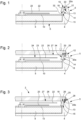
- the case 4, intended for the watch 2 is formed in a single piece defining a back 6 and a caseband-bezel. Other variants with a separate back and/or a bezel separate from the caseband are also envisaged. It will be noted that, in the description of the invention, the terminology used distinguishes, for the sake of clarity, the case 4 from the flange 18 and the crystal 26 which thus form three separate elements which are initially separate.
- the case comprises an upper part 5 which has a first shoulder defining an annular surface 13, which is horizontal in the variant described. By 'horizontal surface' is meant a surface perpendicular to a central axis of the case 4.
- This annular surface is intended to be bonded with a peripheral lower surface 25 of an inner face 27 of the crystal 26, the peripheral lower surface defining a surface parallel to this annular surface.
- the peripheral lower surface of the glass is generally parallel to the annular surface, this annular surface or the peripheral lower surface being parallel except for example in a median annular zone where an annular groove is provided, located substantially in the middle of the width of the annular surface, to form a recess for receiving a glue 20a provided for assembling the glass to the box and thus forming a median zone of the watertight seal 20b, obtained following this assembly, with a greater thickness of glue.
- the upper part 5 of the case 4 defines an inner vertical surface 14 which limits the annular surface 13 on the inner side of the case, this inner vertical surface descending from the inner periphery of the annular surface.
- the upper part 5 comprises a projecting part forming a rim 12, which defines a side wall 28 which rises vertically from the outer periphery of the annular surface 13, this vertical side wall being provided to radially surround, in a conventional manner, the glass 26 once the latter is placed in the upper opening of the bezel of the case 4 to close this case.
- the adjective 'vertical' and the adverb 'vertically' respectively mean 'axial' and 'axially', that is to say along a central axis of the watch case.
- watch 2 further comprises a flange 18 which is distinct from the upper part 5 of the case and which is sized to be able to be inserted by force, along an insertion axis coincident with the central axis of the case, into an opening of the upper part 5, along the interior vertical surface 14 which defines this opening.
- This interior vertical surface limits the annular surface of the central side of the case.
- the flange 18 has an upper surface 19 provided opposite a contact surface 29 of the inner face 27 of the glass once the glass is mounted in the case, this contact surface 29 being adjacent to the peripheral lower surface 25.
- the upper surface 19 and the contact surface 29 are configured so that there is at least one continuous annular contact zone between these two surfaces when the glass 26 is applied against the flange 18 once this glass is inserted into the housing formed by the upper opening of the bezel of the case 4.
- the upper surface 19 and the contact surface 29 of the glass are parallel.
- the case also comprises a second shoulder forming a stop 15 for the flange 18.
- the stop provided to define a final axial positioning of the flange 18 or a lower limit for this flange, can also be formed by a casing circle provided for the movement 8, by the movement itself or by the dial 10 arranged above the movement.
- the stop provided for the flange 18 it is preferable for the stop provided for the flange 18 to be formed by the case itself. More generally, it is advantageous for the annular surface 13 and the stop 15 to be defined by the same part, which makes it possible to precisely manage the axial distance between the annular surface 13 and the stop 15.
- the stop 15 defines an annular stop surface which is parallel to a lower surface 32 of the flange, which is located opposite this annular stop surface once the flange is introduced along the interior vertical surface 14 of the case 4.
- the interior vertical surface 14 of the case 4 is parallel to at least one continuous annular zone of the external lateral surface 30 of the flange, which is configured such that this continuous annular zone is continuously in contact with the internal vertical surface 14 once this continuous annular zone is inserted along the internal vertical surface.
- the continuous annular zone is formed by a lower part of the external lateral surface 30 of the flange.
- the internal vertical surface 14 of the case 4 is parallel to the external lateral surface of the flange, at least to the part of this external lateral surface which is provided opposite the internal vertical surface once the flange is in its final position in the case 4.
- the introduction of the movement 8 with the dial 10 from the top can, in a variant, be provided between the deposition of the glue and the partial insertion of the flange mentioned above.
- the case comprises a back which is provided to be removable relative to the caseband
- the introduction of the movement and the dial with the analog display can take place from the bottom, that is to say through an opening intended to be closed by the back, following the assembly method.
- the flange 18 is brought into abutment against the stop 15 at the end of the step of exerting axial pressure on the outer face of the glass.
- the lower surface 32 of the flange then bears against an entire annular stop surface, which is defined by the stop.
- a stop for the flange can be formed by the dial 10.
- this latter variant presents a problem of tolerances, so that it is more difficult to be able to properly manage the final level of the upper surface 19 of the flange at the end of the step of exerting axial pressure.
- the upper surface 19 of the flange 18 is located axially above the annular surface 13 of the case, at an axial distance greater than 20 microns (20 ⁇ m) and less than or equal to 100 microns (100 ⁇ m).
- an axial distance between 60 and 70 microns (60 - 70 ⁇ m) will be taken as a set value, for example. This makes it possible to ensure that the watertight seal 20b, formed by the glue 20a and obtained after the step of hardening this glue, has a certain non-zero thickness.
- a certain thickness of the adhesive joint 20b can be obtained by structuring the annular surface 13 or the corresponding peripheral lower surface 25.
- the annular surface has a structuring defining hollow zones and/or paths for the adhesive 20a.
- the spacers are incorporated into the adhesive 20a to ensure a minimum thickness for the sealed joint 20b over the entire annular surface 13.
- the thickness of the adhesive before hardening can be well managed. It will be noted that in this other mode, the presence of a stop 15 to determine a final axial positioning of the flange is not essential to prevent the flange from finally arriving at the same level as the annular surface 13, because it is the aforementioned structuring or the spacers, in particular glass beads or synthetic beads, which guarantee that the axial pressure exerted on the glass 26 does not bring these two surfaces to the same level, that is to say to the same axial position.
- the exertion of axial pressure on the outer face of the glass 26 is preferably maintained at least during a first part of the step of hardening the glue 20a.
- the upper part 5 of the box 4 comprises a projecting part forming a rim 12 which defines a side wall 28 rising axially from the outer periphery of the annular surface 13, this side wall radially surrounding the glass 26 at the end of the step of exerting axial pressure on the outer face of the glass.
- the quantity of glue 20a provided during the step of depositing a glue is provided such that, during the step of exerting axial pressure on the outer face of the glass, a portion of the glue rises into a slot left between a side face of the glass and the side wall 28 of the rim 12.
- the sealed seal 20b formed completely covers the annular surface 13 and at least partially fills the slot.
- This slot therefore has the function of a reservoir for receiving excess glue, in addition to also participating in fixing the glass 26 to the box 4 by gluing and ensuring sufficient sealing of the glue joint 20b obtained.
Landscapes
- Physics & Mathematics (AREA)
- General Physics & Mathematics (AREA)
- Chemical & Material Sciences (AREA)
- Crystallography & Structural Chemistry (AREA)
- Electric Clocks (AREA)
- Standing Axle, Rod, Or Tube Structures Coupled By Welding, Adhesion, Or Deposition (AREA)
- Joining Of Glass To Other Materials (AREA)
- Lining Or Joining Of Plastics Or The Like (AREA)
- Table Devices Or Equipment (AREA)
Claims (10)
- Verfahren zum Zusammenbau eines Glases (26) mit einem Gehäuse (4) zum Bilden einer Uhr (2), wobei das Gehäuse eine ringförmige Oberfläche (13) aufweist, die dazu vorgesehen ist, auf eine untere Umfangsoberfläche (25) einer Innenfläche (27) des Glases geklebt zu werden; dadurch gekennzeichnet, dass die Uhr einen Höhenring (18) umfasst, der eine obere Oberfläche (19) aufweist und bemessen ist, um entlang einer Fügeachse entlang einer inneren vertikalen Oberfläche (14) eines oberen Teils (5) des Gehäuses eingepresst zu werden, wobei die innere vertikale Oberfläche (14) die ringförmige Oberfläche (13) auf der zentralen Seite des Gehäuses begrenzt;wobei dieses Verfahren zum Zusammenbau die folgenden Schritte umfasst:- teilweises Einfügen des Höhenrings ins Innere einer von der inneren vertikalen Oberfläche (14) definierten Öffnung;- Aufbringen eines Klebstoffs (20a) auf die ringförmige Oberfläche (13) des Gehäuses und/oder auf die untere Umfangsoberfläche (25);und danach die folgenden Schritte:- Anlegen des Glases an die obere Oberfläche (19) des Höhenrings (18) in einer horizontalen Endposition des Glases, in der seine untere Umfangsoberfläche (25) die ringförmige Fläche (13) axial überlagert, wobei die obere Oberfläche (19) des Höhenrings somit mit einer Kontaktoberfläche (29) der Innenfläche (27) des Glases angrenzend an die untere Umfangsoberfläche (25) in Kontakt steht, wobei diese Kontaktoberfläche (29) und die obere Oberfläche (19) des Höhenrings konfiguriert sind, sodass zwischen diesen beiden Oberflächen mindestens eine kontinuierliche ringförmige Kontaktzone besteht;- Ausüben eines axialen Drucks auf eine Außenfläche des Glases mit einer Intensität, die es ermöglicht, das Einfügen des Höhenrings in die Öffnung nach und nach fortzusetzen, bis die obere Oberfläche (19) des Höhenrings eine axiale Endposition erreicht hat, die über der ringförmigen Oberfläche (13) vorgesehen ist, und bis die untere Umfangsoberfläche (25) des Glases von dem Klebstoff bedeckt ist, um einen durchgehenden Klebstoffring zwischen der ringförmigen Oberfläche (13) des Gehäuses und der unteren Umfangsoberfläche (25) des Glases zu bilden;- Aushärten des Klebstoffs, um eine dichte Dichtung (20b) zu bilden.
- Verfahren zum Zusammenbau nach Anspruch 1, dadurch gekennzeichnet, dass das Gehäuse (4) eine Schulter umfasst, die einen Anschlag (15) für den Höhenring (18) bildet.
- Verfahren zum Zusammenbau nach Anspruch 2, dadurch gekennzeichnet, dass der Anschlag (15) eine ringförmige, Anschlagoberfläche definiert, die durchgehend und parallel zu einer unteren Oberfläche (32) des Höhenrings ist, die am Ende des Schritts des Ausübens eines axialen Drucks auf die Außenoberfläche des Glases auf der gesamten durchgehenden ringförmigen Anschlagoberfläche aufliegt.
- Verfahren zum Zusammenbau nach einem der vorstehenden Ansprüche, dadurch gekennzeichnet, dass die innere vertikale Oberfläche (14) parallel zu mindestens einer durchgehenden ringförmigen Zone einer äußeren Seitenoberfläche (30) des Höhenrings ist, die konfiguriert ist, sodass diese durchgehende ringförmige Zone kontinuierlich in Kontakt mit der inneren vertikalen Oberfläche (14) ist, sobald diese durchgehende ringförmige Zone entlang dieser inneren vertikalen Oberfläche eingeführt worden ist.
- Verfahren zum Zusammenbau nach einem der vorstehenden Ansprüche, dadurch gekennzeichnet, dass der axiale Druck auf die Außenoberfläche des Glases (26) zumindest während eines ersten Teils des Schrittes des Aushärtens des Klebers aufrechterhalten wird.
- Verfahren zum Zusammenbau nach einem der vorstehenden Ansprüche, dadurch gekennzeichnet, dass am Ende des Schritts des Ausübens eines axialen Drucks auf die Außenoberfläche des Glases (26) die obere Oberfläche (19) sich oberhalb der ringförmigen Oberfläche (13) in einem axialen Abstand von mehr als 20 Mikrometer und weniger als 100 Mikrometer befindet.
- Verfahren zum Zusammenbau nach einem der vorstehenden Ansprüche, dadurch gekennzeichnet, dass die ringförmige Oberfläche (13) des Gehäuses oder die untere Umfangsoberfläche (25) des Glases (26) eine Strukturierung aufweist, die konkave Zonen und/oder Hohlwege für den Klebstoff definiert.
- Verfahren zum Zusammenbau nach einem der Ansprüche 1 bis 6, dadurch gekennzeichnet, dass Abstandshalter in den Klebstoff (20a) eingearbeitet werden, um eine Mindestdicke der dichten Dichtung (20b) über die gesamte ringförmige Oberfläche (13) zu gewährleisten.
- Verfahren zum Zusammenbau nach einem der vorstehenden Ansprüche, dadurch gekennzeichnet, dass der obere Teil (5) des Gehäuses einen vorspringenden Teil umfasst, der einen Rand (12) bildet, der eine Seitenwand (28) definiert, die sich axial aus dem Außenumfang der ringförmigen Oberfläche erhebt, wobei diese Seitenwand das Glas am Ende des Schritts des Ausübens eines axialen Drucks auf die Außenoberfläche des Glases radial umgibt.
- Verfahren zum Zusammenbau nach Anspruch 9, dadurch gekennzeichnet, dass die im Schritt des Aufbringens eines Klebstoffs beigebrachte Klebstoffmenge vorgesehen ist, sodass im Schritt des Ausübens eines axialen Drucks auf die Außenoberfläche des Glases ein Teil des Klebstoffs in einen zwischen einer Seitenfläche des Glases und der Seitenwand des Randes belassenen Schlitz aufsteigt, wobei die gebildete dichte Dichtung (20b) die ringförmige Oberfläche vollständig bedeckt und den Schlitz zumindest teilweise ausfüllt.
Applications Claiming Priority (1)
| Application Number | Priority Date | Filing Date | Title |
|---|---|---|---|
| EP22166760 | 2022-04-05 |
Publications (2)
| Publication Number | Publication Date |
|---|---|
| EP4258065A1 EP4258065A1 (de) | 2023-10-11 |
| EP4258065B1 true EP4258065B1 (de) | 2024-12-25 |
Family
ID=81307462
Family Applications (1)
| Application Number | Title | Priority Date | Filing Date |
|---|---|---|---|
| EP23160375.4A Active EP4258065B1 (de) | 2022-04-05 | 2023-03-07 | Verfahren zum zusammenbau eines glases mit einem armbanduhrgehäuse |
Country Status (5)
| Country | Link |
|---|---|
| US (1) | US12416900B2 (de) |
| EP (1) | EP4258065B1 (de) |
| JP (1) | JP7499909B2 (de) |
| KR (1) | KR102815611B1 (de) |
| CN (2) | CN219512521U (de) |
Families Citing this family (1)
| Publication number | Priority date | Publication date | Assignee | Title |
|---|---|---|---|---|
| USD1035460S1 (en) * | 2021-05-21 | 2024-07-16 | Mobvoi Information Technology Company Limited | Watch case |
Family Cites Families (14)
| Publication number | Priority date | Publication date | Assignee | Title |
|---|---|---|---|---|
| CH302614A (fr) * | 1951-08-06 | 1954-10-31 | Morf Ernest | Montre. |
| GB1303914A (de) * | 1970-04-24 | 1973-01-24 | ||
| JPS5352153A (en) * | 1976-10-22 | 1978-05-12 | Seiko Instr & Electronics Ltd | Fixing structure of glass part for watches |
| JPS53134973U (de) * | 1977-03-31 | 1978-10-25 | ||
| CH622151B (fr) | 1977-07-15 | Hans Ulrich Klingenberg | Boite de montre. | |
| JPS5627686U (de) | 1979-08-07 | 1981-03-14 | ||
| FR2524992A1 (fr) | 1982-04-13 | 1983-10-14 | Omega Brandt & Freres Sa Louis | Boite de montre etanche |
| JP2006105654A (ja) * | 2004-10-01 | 2006-04-20 | Citizen Seimitsu Co Ltd | 腕時計の防水構造 |
| CH709838B1 (fr) * | 2014-07-01 | 2018-08-15 | The Swatch Group Man Services Ag | Montre comportant une boîte de montre. |
| JP6608714B2 (ja) * | 2016-01-21 | 2019-11-20 | セイコーインスツル株式会社 | 時計 |
| JP6531754B2 (ja) * | 2016-12-21 | 2019-06-19 | カシオ計算機株式会社 | 機器ケース及び時計 |
| RU2019139053A (ru) * | 2017-05-09 | 2021-06-09 | Геа Фуд Сольюшнс Бакел Б.В. | Установка и соответствующие промышленные применения с использованием технологии на основе твердотельных рч-источников энергии |
| CH713959B1 (fr) * | 2017-07-07 | 2021-09-15 | Swatch Group Res & Dev Ltd | Procédé d'assemblage d'une glace à une boîte de montre. |
| CH714277B1 (fr) * | 2017-10-16 | 2022-03-15 | Richemont Int Sa | Procédé de fixation d'une glace sur un élément d'habillage pour boîte de pièce d'horlogerie. |
-
2023
- 2023-03-07 EP EP23160375.4A patent/EP4258065B1/de active Active
- 2023-03-14 US US18/183,508 patent/US12416900B2/en active Active
- 2023-03-24 KR KR1020230038817A patent/KR102815611B1/ko active Active
- 2023-03-29 JP JP2023053014A patent/JP7499909B2/ja active Active
- 2023-04-04 CN CN202320715029.2U patent/CN219512521U/zh active Active
- 2023-04-04 CN CN202310349534.4A patent/CN116893604A/zh active Pending
Also Published As
| Publication number | Publication date |
|---|---|
| KR20230143568A (ko) | 2023-10-12 |
| CN116893604A (zh) | 2023-10-17 |
| US20230315021A1 (en) | 2023-10-05 |
| US12416900B2 (en) | 2025-09-16 |
| JP2023153748A (ja) | 2023-10-18 |
| JP7499909B2 (ja) | 2024-06-14 |
| EP4258065A1 (de) | 2023-10-11 |
| CN219512521U (zh) | 2023-08-11 |
| KR102815611B1 (ko) | 2025-05-30 |
Similar Documents
| Publication | Publication Date | Title |
|---|---|---|
| EP2196868B1 (de) | Spirale mit Kurvenerhöhung aus Material auf Siliziumbasis | |
| EP2656151B1 (de) | Montage einer komponente ohne kunststoffbereich | |
| EP2469354B1 (de) | Zusammenbau eines Teils, das keinen Plastikbereich enthält | |
| EP2442190A1 (de) | Zusammenbau eines Teils, das keinen Plastikbereich enthält | |
| EP4258065B1 (de) | Verfahren zum zusammenbau eines glases mit einem armbanduhrgehäuse | |
| EP2791739B1 (de) | Stosssicheres lager für uhr | |
| EP3736642B1 (de) | Wasserdichtes armbanduhrgehäuse | |
| EP0980543B1 (de) | Verfahren zur herstellung eines uhrengehäuses | |
| EP2717437B1 (de) | Elektromagnetischer Motor für elektronisches Uhrwerk mit Analoganzeige | |
| WO2015144382A1 (fr) | Piece d'horlogerie pourvue d'un cadran et methode de fixation associee | |
| CH719574A2 (fr) | Procédé d'assemblage d'un verre à une boîte de montre | |
| EP0549978B1 (de) | Verfahren zum Anbringen eines Glases auf einem Uhrengehäuse sowie Uhr mit Mitteln zum Ausrichten eines Glases auf einem Gehäuse | |
| EP4071557B1 (de) | Gehäuseelement für uhr, das einen drücker aus massivem metallischem glas umfasst | |
| EP0097393B1 (de) | Armbanduhrgehäuse | |
| EP0334182B1 (de) | Uhrengehäuse mit einem Mantel | |
| EP1102136B1 (de) | Vorrichtung zum Aufsetzen einer Schutzkappe aus hartem Material auf den Mittelteil einer Uhr | |
| EP0111449A2 (de) | Verfahren zur Herstellung eines äusseren Uhrenteils und durch dieses Verfahren hergestelltes Teil | |
| EP0129274A1 (de) | Wasserdichtes Uhrengehäuse | |
| EP2360537B1 (de) | Verfahren und Vorrichtung zur Fixierung eines Glases mit Gegenplatte | |
| CH714277A2 (fr) | Procédé de fixation d'une glace sur un élément d'habillage pour boîte de pièce d'horlogerie. | |
| CH716692B1 (fr) | Procédé de fabrication d'un composant, typiquement horloger, en silicium. | |
| EP4198646B1 (de) | Wasserdichtes armbanduhrgehäuse mit fixierdichtung | |
| EP1276023B1 (de) | Befestigungsvorrichtung für ein Zifferblatt in einem Uhrgehäuse | |
| EP0082840A1 (de) | Wasserdichtes uhrgehäuse. | |
| CH702656A2 (fr) | Procede et dispositif de fixation d'une glace avec contre-lame. |
Legal Events
| Date | Code | Title | Description |
|---|---|---|---|
| PUAI | Public reference made under article 153(3) epc to a published international application that has entered the european phase |
Free format text: ORIGINAL CODE: 0009012 |
|
| STAA | Information on the status of an ep patent application or granted ep patent |
Free format text: STATUS: THE APPLICATION HAS BEEN PUBLISHED |
|
| AK | Designated contracting states |
Kind code of ref document: A1 Designated state(s): AL AT BE BG CH CY CZ DE DK EE ES FI FR GB GR HR HU IE IS IT LI LT LU LV MC ME MK MT NL NO PL PT RO RS SE SI SK SM TR |
|
| P01 | Opt-out of the competence of the unified patent court (upc) registered |
Effective date: 20231109 |
|
| STAA | Information on the status of an ep patent application or granted ep patent |
Free format text: STATUS: REQUEST FOR EXAMINATION WAS MADE |
|
| 17P | Request for examination filed |
Effective date: 20240411 |
|
| RBV | Designated contracting states (corrected) |
Designated state(s): AL AT BE BG CH CY CZ DE DK EE ES FI FR GB GR HR HU IE IS IT LI LT LU LV MC ME MK MT NL NO PL PT RO RS SE SI SK SM TR |
|
| GRAP | Despatch of communication of intention to grant a patent |
Free format text: ORIGINAL CODE: EPIDOSNIGR1 |
|
| STAA | Information on the status of an ep patent application or granted ep patent |
Free format text: STATUS: GRANT OF PATENT IS INTENDED |
|
| INTG | Intention to grant announced |
Effective date: 20240823 |
|
| GRAS | Grant fee paid |
Free format text: ORIGINAL CODE: EPIDOSNIGR3 |
|
| GRAA | (expected) grant |
Free format text: ORIGINAL CODE: 0009210 |
|
| STAA | Information on the status of an ep patent application or granted ep patent |
Free format text: STATUS: THE PATENT HAS BEEN GRANTED |
|
| AK | Designated contracting states |
Kind code of ref document: B1 Designated state(s): AL AT BE BG CH CY CZ DE DK EE ES FI FR GB GR HR HU IE IS IT LI LT LU LV MC ME MK MT NL NO PL PT RO RS SE SI SK SM TR |
|
| REG | Reference to a national code |
Ref country code: GB Ref legal event code: FG4D Free format text: NOT ENGLISH |
|
| REG | Reference to a national code |
Ref country code: CH Ref legal event code: EP |
|
| REG | Reference to a national code |
Ref country code: DE Ref legal event code: R096 Ref document number: 602023001445 Country of ref document: DE |
|
| REG | Reference to a national code |
Ref country code: IE Ref legal event code: FG4D Free format text: LANGUAGE OF EP DOCUMENT: FRENCH |
|
| REG | Reference to a national code |
Ref country code: LT Ref legal event code: MG9D |
|
| PG25 | Lapsed in a contracting state [announced via postgrant information from national office to epo] |
Ref country code: HR Free format text: LAPSE BECAUSE OF FAILURE TO SUBMIT A TRANSLATION OF THE DESCRIPTION OR TO PAY THE FEE WITHIN THE PRESCRIBED TIME-LIMIT Effective date: 20241225 |
|
| PGFP | Annual fee paid to national office [announced via postgrant information from national office to epo] |
Ref country code: DE Payment date: 20250218 Year of fee payment: 3 |
|
| PG25 | Lapsed in a contracting state [announced via postgrant information from national office to epo] |
Ref country code: FI Free format text: LAPSE BECAUSE OF FAILURE TO SUBMIT A TRANSLATION OF THE DESCRIPTION OR TO PAY THE FEE WITHIN THE PRESCRIBED TIME-LIMIT Effective date: 20241225 |
|
| PG25 | Lapsed in a contracting state [announced via postgrant information from national office to epo] |
Ref country code: BG Free format text: LAPSE BECAUSE OF FAILURE TO SUBMIT A TRANSLATION OF THE DESCRIPTION OR TO PAY THE FEE WITHIN THE PRESCRIBED TIME-LIMIT Effective date: 20241225 |
|
| PG25 | Lapsed in a contracting state [announced via postgrant information from national office to epo] |
Ref country code: NO Free format text: LAPSE BECAUSE OF FAILURE TO SUBMIT A TRANSLATION OF THE DESCRIPTION OR TO PAY THE FEE WITHIN THE PRESCRIBED TIME-LIMIT Effective date: 20250325 |
|
| PG25 | Lapsed in a contracting state [announced via postgrant information from national office to epo] |
Ref country code: LV Free format text: LAPSE BECAUSE OF FAILURE TO SUBMIT A TRANSLATION OF THE DESCRIPTION OR TO PAY THE FEE WITHIN THE PRESCRIBED TIME-LIMIT Effective date: 20241225 Ref country code: GR Free format text: LAPSE BECAUSE OF FAILURE TO SUBMIT A TRANSLATION OF THE DESCRIPTION OR TO PAY THE FEE WITHIN THE PRESCRIBED TIME-LIMIT Effective date: 20250326 |
|
| PGFP | Annual fee paid to national office [announced via postgrant information from national office to epo] |
Ref country code: AT Payment date: 20250417 Year of fee payment: 3 |
|
| PGFP | Annual fee paid to national office [announced via postgrant information from national office to epo] |
Ref country code: FR Payment date: 20250219 Year of fee payment: 3 |
|
| PG25 | Lapsed in a contracting state [announced via postgrant information from national office to epo] |
Ref country code: RS Free format text: LAPSE BECAUSE OF FAILURE TO SUBMIT A TRANSLATION OF THE DESCRIPTION OR TO PAY THE FEE WITHIN THE PRESCRIBED TIME-LIMIT Effective date: 20250325 |
|
| REG | Reference to a national code |
Ref country code: NL Ref legal event code: MP Effective date: 20241225 |
|
| PG25 | Lapsed in a contracting state [announced via postgrant information from national office to epo] |
Ref country code: NL Free format text: LAPSE BECAUSE OF FAILURE TO SUBMIT A TRANSLATION OF THE DESCRIPTION OR TO PAY THE FEE WITHIN THE PRESCRIBED TIME-LIMIT Effective date: 20241225 |
|
| REG | Reference to a national code |
Ref country code: AT Ref legal event code: MK05 Ref document number: 1754693 Country of ref document: AT Kind code of ref document: T Effective date: 20241225 |
|
| PG25 | Lapsed in a contracting state [announced via postgrant information from national office to epo] |
Ref country code: SM Free format text: LAPSE BECAUSE OF FAILURE TO SUBMIT A TRANSLATION OF THE DESCRIPTION OR TO PAY THE FEE WITHIN THE PRESCRIBED TIME-LIMIT Effective date: 20241225 |
|
| PG25 | Lapsed in a contracting state [announced via postgrant information from national office to epo] |
Ref country code: PL Free format text: LAPSE BECAUSE OF FAILURE TO SUBMIT A TRANSLATION OF THE DESCRIPTION OR TO PAY THE FEE WITHIN THE PRESCRIBED TIME-LIMIT Effective date: 20241225 |
|
| PG25 | Lapsed in a contracting state [announced via postgrant information from national office to epo] |
Ref country code: ES Free format text: LAPSE BECAUSE OF FAILURE TO SUBMIT A TRANSLATION OF THE DESCRIPTION OR TO PAY THE FEE WITHIN THE PRESCRIBED TIME-LIMIT Effective date: 20241225 |
|
| PG25 | Lapsed in a contracting state [announced via postgrant information from national office to epo] |
Ref country code: IS Free format text: LAPSE BECAUSE OF FAILURE TO SUBMIT A TRANSLATION OF THE DESCRIPTION OR TO PAY THE FEE WITHIN THE PRESCRIBED TIME-LIMIT Effective date: 20250425 |
|
| PG25 | Lapsed in a contracting state [announced via postgrant information from national office to epo] |
Ref country code: PT Free format text: LAPSE BECAUSE OF FAILURE TO SUBMIT A TRANSLATION OF THE DESCRIPTION OR TO PAY THE FEE WITHIN THE PRESCRIBED TIME-LIMIT Effective date: 20250428 |
|
| PG25 | Lapsed in a contracting state [announced via postgrant information from national office to epo] |
Ref country code: EE Free format text: LAPSE BECAUSE OF FAILURE TO SUBMIT A TRANSLATION OF THE DESCRIPTION OR TO PAY THE FEE WITHIN THE PRESCRIBED TIME-LIMIT Effective date: 20241225 |
|
| PG25 | Lapsed in a contracting state [announced via postgrant information from national office to epo] |
Ref country code: RO Free format text: LAPSE BECAUSE OF FAILURE TO SUBMIT A TRANSLATION OF THE DESCRIPTION OR TO PAY THE FEE WITHIN THE PRESCRIBED TIME-LIMIT Effective date: 20241225 Ref country code: AT Free format text: LAPSE BECAUSE OF FAILURE TO SUBMIT A TRANSLATION OF THE DESCRIPTION OR TO PAY THE FEE WITHIN THE PRESCRIBED TIME-LIMIT Effective date: 20241225 |
|
| PG25 | Lapsed in a contracting state [announced via postgrant information from national office to epo] |
Ref country code: SK Free format text: LAPSE BECAUSE OF FAILURE TO SUBMIT A TRANSLATION OF THE DESCRIPTION OR TO PAY THE FEE WITHIN THE PRESCRIBED TIME-LIMIT Effective date: 20241225 |
|
| PG25 | Lapsed in a contracting state [announced via postgrant information from national office to epo] |
Ref country code: CZ Free format text: LAPSE BECAUSE OF FAILURE TO SUBMIT A TRANSLATION OF THE DESCRIPTION OR TO PAY THE FEE WITHIN THE PRESCRIBED TIME-LIMIT Effective date: 20241225 |
|
| PG25 | Lapsed in a contracting state [announced via postgrant information from national office to epo] |
Ref country code: IT Free format text: LAPSE BECAUSE OF FAILURE TO SUBMIT A TRANSLATION OF THE DESCRIPTION OR TO PAY THE FEE WITHIN THE PRESCRIBED TIME-LIMIT Effective date: 20241225 |
|
| PG25 | Lapsed in a contracting state [announced via postgrant information from national office to epo] |
Ref country code: SE Free format text: LAPSE BECAUSE OF FAILURE TO SUBMIT A TRANSLATION OF THE DESCRIPTION OR TO PAY THE FEE WITHIN THE PRESCRIBED TIME-LIMIT Effective date: 20241225 |
|
| REG | Reference to a national code |
Ref country code: DE Ref legal event code: R097 Ref document number: 602023001445 Country of ref document: DE |
|
| PG25 | Lapsed in a contracting state [announced via postgrant information from national office to epo] |
Ref country code: DK Free format text: LAPSE BECAUSE OF FAILURE TO SUBMIT A TRANSLATION OF THE DESCRIPTION OR TO PAY THE FEE WITHIN THE PRESCRIBED TIME-LIMIT Effective date: 20241225 |
|
| PG25 | Lapsed in a contracting state [announced via postgrant information from national office to epo] |
Ref country code: MC Free format text: LAPSE BECAUSE OF FAILURE TO SUBMIT A TRANSLATION OF THE DESCRIPTION OR TO PAY THE FEE WITHIN THE PRESCRIBED TIME-LIMIT Effective date: 20241225 |
|
| PLBE | No opposition filed within time limit |
Free format text: ORIGINAL CODE: 0009261 |
|
| STAA | Information on the status of an ep patent application or granted ep patent |
Free format text: STATUS: NO OPPOSITION FILED WITHIN TIME LIMIT |
|
| PG25 | Lapsed in a contracting state [announced via postgrant information from national office to epo] |
Ref country code: LU Free format text: LAPSE BECAUSE OF NON-PAYMENT OF DUE FEES Effective date: 20250307 |
|
| 26N | No opposition filed |
Effective date: 20250926 |