EP4257900B1 - Ensemble charnière linéaire pour appareil - Google Patents
Ensemble charnière linéaire pour appareil Download PDFInfo
- Publication number
- EP4257900B1 EP4257900B1 EP21902459.3A EP21902459A EP4257900B1 EP 4257900 B1 EP4257900 B1 EP 4257900B1 EP 21902459 A EP21902459 A EP 21902459A EP 4257900 B1 EP4257900 B1 EP 4257900B1
- Authority
- EP
- European Patent Office
- Prior art keywords
- door
- pivot axis
- shaft
- axis
- cabinet
- Prior art date
- Legal status (The legal status is an assumption and is not a legal conclusion. Google has not performed a legal analysis and makes no representation as to the accuracy of the status listed.)
- Active
Links
Images


Classifications
-
- E—FIXED CONSTRUCTIONS
- E05—LOCKS; KEYS; WINDOW OR DOOR FITTINGS; SAFES
- E05D—HINGES OR SUSPENSION DEVICES FOR DOORS, WINDOWS OR WINGS
- E05D15/00—Suspension arrangements for wings
- E05D15/56—Suspension arrangements for wings with successive different movements
- E05D15/58—Suspension arrangements for wings with successive different movements with both swinging and sliding movements
- E05D15/581—Suspension arrangements for wings with successive different movements with both swinging and sliding movements the swinging axis laying in the sliding direction
-
- E—FIXED CONSTRUCTIONS
- E05—LOCKS; KEYS; WINDOW OR DOOR FITTINGS; SAFES
- E05D—HINGES OR SUSPENSION DEVICES FOR DOORS, WINDOWS OR WINGS
- E05D3/00—Hinges with pins
- E05D3/06—Hinges with pins with two or more pins
-
- E—FIXED CONSTRUCTIONS
- E05—LOCKS; KEYS; WINDOW OR DOOR FITTINGS; SAFES
- E05D—HINGES OR SUSPENSION DEVICES FOR DOORS, WINDOWS OR WINGS
- E05D3/00—Hinges with pins
- E05D3/06—Hinges with pins with two or more pins
- E05D3/14—Hinges with pins with two or more pins with four parallel pins and two arms
-
- E—FIXED CONSTRUCTIONS
- E05—LOCKS; KEYS; WINDOW OR DOOR FITTINGS; SAFES
- E05D—HINGES OR SUSPENSION DEVICES FOR DOORS, WINDOWS OR WINGS
- E05D3/00—Hinges with pins
- E05D3/06—Hinges with pins with two or more pins
- E05D3/18—Hinges with pins with two or more pins with sliding pins or guides
-
- F—MECHANICAL ENGINEERING; LIGHTING; HEATING; WEAPONS; BLASTING
- F25—REFRIGERATION OR COOLING; COMBINED HEATING AND REFRIGERATION SYSTEMS; HEAT PUMP SYSTEMS; MANUFACTURE OR STORAGE OF ICE; LIQUEFACTION SOLIDIFICATION OF GASES
- F25D—REFRIGERATORS; COLD ROOMS; ICE-BOXES; COOLING OR FREEZING APPARATUS NOT OTHERWISE PROVIDED FOR
- F25D23/00—General constructional features
- F25D23/02—Doors; Covers
- F25D23/028—Details
-
- E—FIXED CONSTRUCTIONS
- E05—LOCKS; KEYS; WINDOW OR DOOR FITTINGS; SAFES
- E05Y—INDEXING SCHEME ASSOCIATED WITH SUBCLASSES E05D AND E05F, RELATING TO CONSTRUCTION ELEMENTS, ELECTRIC CONTROL, POWER SUPPLY, POWER SIGNAL OR TRANSMISSION, USER INTERFACES, MOUNTING OR COUPLING, DETAILS, ACCESSORIES, AUXILIARY OPERATIONS NOT OTHERWISE PROVIDED FOR, APPLICATION THEREOF
- E05Y2201/00—Constructional elements; Accessories therefor
- E05Y2201/60—Suspension or transmission members; Accessories therefor
- E05Y2201/622—Suspension or transmission members elements
- E05Y2201/624—Arms
- E05Y2201/626—Levers
-
- E—FIXED CONSTRUCTIONS
- E05—LOCKS; KEYS; WINDOW OR DOOR FITTINGS; SAFES
- E05Y—INDEXING SCHEME ASSOCIATED WITH SUBCLASSES E05D AND E05F, RELATING TO CONSTRUCTION ELEMENTS, ELECTRIC CONTROL, POWER SUPPLY, POWER SIGNAL OR TRANSMISSION, USER INTERFACES, MOUNTING OR COUPLING, DETAILS, ACCESSORIES, AUXILIARY OPERATIONS NOT OTHERWISE PROVIDED FOR, APPLICATION THEREOF
- E05Y2201/00—Constructional elements; Accessories therefor
- E05Y2201/60—Suspension or transmission members; Accessories therefor
- E05Y2201/622—Suspension or transmission members elements
- E05Y2201/638—Cams; Ramps
-
- E—FIXED CONSTRUCTIONS
- E05—LOCKS; KEYS; WINDOW OR DOOR FITTINGS; SAFES
- E05Y—INDEXING SCHEME ASSOCIATED WITH SUBCLASSES E05D AND E05F, RELATING TO CONSTRUCTION ELEMENTS, ELECTRIC CONTROL, POWER SUPPLY, POWER SIGNAL OR TRANSMISSION, USER INTERFACES, MOUNTING OR COUPLING, DETAILS, ACCESSORIES, AUXILIARY OPERATIONS NOT OTHERWISE PROVIDED FOR, APPLICATION THEREOF
- E05Y2201/00—Constructional elements; Accessories therefor
- E05Y2201/60—Suspension or transmission members; Accessories therefor
- E05Y2201/622—Suspension or transmission members elements
- E05Y2201/686—Rods, links
-
- E—FIXED CONSTRUCTIONS
- E05—LOCKS; KEYS; WINDOW OR DOOR FITTINGS; SAFES
- E05Y—INDEXING SCHEME ASSOCIATED WITH SUBCLASSES E05D AND E05F, RELATING TO CONSTRUCTION ELEMENTS, ELECTRIC CONTROL, POWER SUPPLY, POWER SIGNAL OR TRANSMISSION, USER INTERFACES, MOUNTING OR COUPLING, DETAILS, ACCESSORIES, AUXILIARY OPERATIONS NOT OTHERWISE PROVIDED FOR, APPLICATION THEREOF
- E05Y2201/00—Constructional elements; Accessories therefor
- E05Y2201/60—Suspension or transmission members; Accessories therefor
- E05Y2201/622—Suspension or transmission members elements
- E05Y2201/71—Toothed gearing
- E05Y2201/716—Pinions
-
- E—FIXED CONSTRUCTIONS
- E05—LOCKS; KEYS; WINDOW OR DOOR FITTINGS; SAFES
- E05Y—INDEXING SCHEME ASSOCIATED WITH SUBCLASSES E05D AND E05F, RELATING TO CONSTRUCTION ELEMENTS, ELECTRIC CONTROL, POWER SUPPLY, POWER SIGNAL OR TRANSMISSION, USER INTERFACES, MOUNTING OR COUPLING, DETAILS, ACCESSORIES, AUXILIARY OPERATIONS NOT OTHERWISE PROVIDED FOR, APPLICATION THEREOF
- E05Y2900/00—Application of doors, windows, wings or fittings thereof
- E05Y2900/30—Application of doors, windows, wings or fittings thereof for domestic appliances
- E05Y2900/31—Application of doors, windows, wings or fittings thereof for domestic appliances for refrigerators
-
- F—MECHANICAL ENGINEERING; LIGHTING; HEATING; WEAPONS; BLASTING
- F25—REFRIGERATION OR COOLING; COMBINED HEATING AND REFRIGERATION SYSTEMS; HEAT PUMP SYSTEMS; MANUFACTURE OR STORAGE OF ICE; LIQUEFACTION SOLIDIFICATION OF GASES
- F25D—REFRIGERATORS; COLD ROOMS; ICE-BOXES; COOLING OR FREEZING APPARATUS NOT OTHERWISE PROVIDED FOR
- F25D2323/00—General constructional features not provided for in other groups of this subclass
- F25D2323/02—Details of doors or covers not otherwise covered
- F25D2323/024—Door hinges
Definitions
- the present disclosure relates generally to refrigerator appliances, and more particularly, to linear hinges for refrigerator appliances.
- Refrigerator appliances generally include a cabinet that defines a chilled chamber for receipt of food articles for storage.
- refrigerator appliances include one or more doors rotatably hinged to the cabinet to permit selective access to food items stored in chilled chamber(s).
- the refrigerator appliances can also include various storage components mounted within the chilled chamber and designed to facilitate storage of food items therein.
- Such storage components can include racks, bins, shelves, or drawers that receive food items and assist with organizing and arranging of such food items within the chilled chamber.
- Refrigerator appliances are commonly positioned within a recess in a row of cabinets mounted to a wall in a kitchen.
- certain refrigerator appliances are designed to be flush mount, where the front of the appliance door sits substantially flush with a front of the cabinets when the doors are closed.
- such refrigerators may be designed for receiving a cabinet panel, such that the front appearance of the refrigerator appliance matches the appearance of the cabinetry.
- conventional refrigerator appliances include doors that pivot around a single pivoting axis or hinge, which may cause the door or the panel mounted thereon to rub or conflict with adjacent cabinetry.
- refrigerator doors may frequently experience gasket rub or wear as the door is opened and closed repeatedly.
- US 2020/217115 A1 and EP 3 343 152 A1 disclose such refrigerators of the prior art.
- a refrigerator appliance with an improved hinge assembly would be useful. More particularly, a hinge assembly that reduces the likelihood of contact between the refrigerator door and adjacent cabinetry would be particularly beneficial.
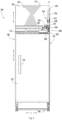
- FIG. 1 is a perspective view of an appliance 100, such as a refrigerator appliance, according to exemplary embodiments of the present disclosure.
- appliance 100 includes a housing or cabinet 102 that extends between a top 104 and a bottom 106 along a vertical direction V, between a first side 108 and a second side 110 along a lateral direction L, and between a front side 112 and a rear side 114 along a transverse direction T.
- Each of the vertical direction V, lateral direction L, and transverse direction T are mutually perpendicular to one another.
- a door 122 is coupled to cabinet 102 with one or more linear hinge assemblies 200 (e.g., located at a top and a bottom of door 122).
- a user may rotate door 122 open to access and interior of cabinet 102 (e.g., chilled chamber 120), and the user may rotate door 122 closed to seal the interior of cabinet 102.
- Door 122 may also include a handle 124 that a user may pull when opening and closing door 122.
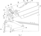
- Linear hinge assemblies 200 will be described herein in more detail according to exemplary embodiments of the present disclosure. In general, linear hinges are used to allow doors to translate away from adjacent cabinetry or appliances in addition to rotating open and closed. By translating in addition to rotating, interference between the doors and the adjacent cabinetry or the appliance itself can be avoided.
- refrigerator appliance 100 may include bottom hinge assemblies that are substantially similar to the top linear hinge assemblies 200.
- distal end portion 222 of elongated shaft 220 is rotatably connected to door 122 (e.g., at shaft bracket 228).
- door 122 is rotatable about a door axis D offset from and translatable relative to elongated shaft 220.
- the door axis D may be perpendicular to the translation axis A.
- the door axis D may be vertically oriented (e.g., parallel to the vertical direction V), and the translation axis A may be horizontally oriented.
- Elongated shaft 220 defines two or more shaft pivot axes coupled to separate linkages (e.g., via corresponding connection pins).
- elongated shaft 220 may define a first shaft pivot axis P1 at which a door linkage 230 is pivotally connected (e.g., via a corresponding connection pin extending along first shaft pivot axis P1) to couple door 122 to elongated shaft 220.
- elongated shaft 220 may define a second shaft pivot axis P2 at which a cabinet linkage 232 is pivotally connected (e.g., via a corresponding connection pin extending along second shaft pivot axis P2) to couple cabinet 102 to elongated shaft 220.
- first shaft pivot axis P1 and second shaft pivot axis P2 are perpendicular to the translation axis A. Moreover, first shaft pivot axis P1 and second shaft pivot axis P2 may be parallel to each other. As shown, first shaft pivot axis P1 and second shaft pivot axis P2 may be vertically oriented (e.g., parallel to the vertical direction V). In some embodiments, the first shaft pivot axis P1 is spaced apart from the second shaft pivot axis P2, as illustrated in FIGS. 1 through 7 , 9 , 10 , and 12 . Specifically, first shaft pivot axis P1 may be positioned apart from second shaft pivot axis P2 along the translation axis A.
- first shaft pivot axis P1 may be positioned forward from second shaft pivot axis P2 such that first shaft pivot axis P1 is closer to door 122 relative to the transverse direction T than second shaft pivot axis P2.
- first shaft pivot axis P1 may proximal to door 122 in comparison to second shaft pivot axis P2 along the translation axis A.
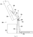
- first shaft pivot axis P1 and second shaft pivot axis P2 are coaxial or concentric with each other, as illustrated in FIGS. 8 and 11 .
- a third shaft pivot axis P3 is defined on elongated shaft 220.
- third shaft pivot axis P3 may be defined parallel to first shaft pivot axis P1 or second shaft pivot axis P2 (e.g., vertically oriented).
- third shaft pivot axis P3 is defined forward from first shaft pivot axis P1 or second shaft pivot axis P2 along the translation axis A (e.g., as the forwardmost shaft pivot axis).
- an offset link 234 may pivotally connect to elongated shaft 220 at a joint 240 defining third shaft pivot axis P3 (e.g., as or including a corresponding connection pin extending along third shaft pivot axis P3) to further couple elongated shaft 220 to door 122.
- offset link 234 also pivotally connects to door 122 at door axis D (e.g., via a corresponding connection pin extending along door axis D).
- offset link 234 may rotate about both door axis D and third shaft pivot axis P3.
- one or more slider pins 242 may be fixed to door linkage 230 while extending (e.g., vertically) through guide path 244, which may be defined on a support bracket 246 fixed to door 122, as illustrated in FIGS. 1 through 10 .
- guide path 244 may be defined on a support bracket 246 fixed to door 122, as illustrated in FIGS. 1 through 10 .
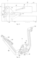
- a single rigid slider bar 248 may be fixed to door linkage 230 while being slidably mated to a rail 249 defining a guide path (e.g., as illustrated in FIG. 12 ), or another suitable sliding connection may be formed as would be understood.
- guide path 244 When door 122 is in the closed position, guide path 244 may extend, at least in part along the lateral direction L (e.g., at a nonorthogonal angle relative thereto). Thus, opposite path ends 250, 252 of guide path 244 may be laterally spaced apart when door 122 is in the closed position.
- An outer end 250 of guide path 244 may be distal to door axis D while an inner end 252 of guide path 244 is proximal to door axis D (e.g., along a horizontal direction, such as the lateral direction L).
- guided end 238 of door linkage 230 e.g., at least one slider pin 242
- guided end 238 (e.g., at least one slider pin 242) may be disposed at or proximal to the inner end 252.
- guide path 244 may be rotated outward and guided end 238 may slide along guide path 244 to move the guided end 238 away from the outer end 250 and closer to the inner end 252.
- guide path 244 may be rotated inward and guided end 238 may slide along guide path 244 to move the guided end 238 away from the inner end 252 and closer to the outer end 250.
- door linkage 230 is arranged such that at least a portion of the rotational force of door linkage 230 about first shaft pivot axis P1 is directed to cabinet linkage 232.
- shaft end 236 of door linkage 230 may be in mechanical communication with an extendable end 254 of cabinet linkage 232.
- an intermediate link 258 may be provided, as shown in FIGS. 1 through 7 .
- intermediate link 258 is movably mounted on elongated shaft 220 at a location that is between first shaft pivot axis P1 and second shaft pivot axis P2 (e.g., between P1 and P2 along or relative to translation axis A).
- intermediate link 258 may extend between a first cam axis C1 and a second cam axis C2, both of which may be parallel to first shaft pivot axis P1 and second shaft pivot axis P2.
- intermediate link 258 may be coupled to door linkage 230 at first cam axis C1 and to cabinet linkage 232 at second cam axis C2 (e.g., via discrete corresponding connection pins).
- First cam axis C1 of intermediate link 258 may specifically couple to the shaft end 236 of door linkage 230 while second cam axis C2 couples to the extendable end 254 of cabinet linkage 232.
- an intermediate gear set 260 may be provided, as shown in various embodiments between FIGS. 8 through 12 .
- intermediate gear set 260 may be enmeshed in mechanical communication between the door linkage 230 at the first shaft pivot axis P1 and the cabinet linkage 232 at the second shaft pivot axis P2.
- mated gear teeth may be provided on the shaft end 236 of door linkage 230 and the extendable end 254 of cabinet linkage 232.
- two or more scissor gear arms may be provided with one end (e.g., arm) coupled to the coaxial first and second shaft pivot axes P1, P2 and another arm coupled to door 122 (e.g., at a separate gear axis).
- Cabinet linkage 232 generally includes one or more rigid arms or gears that further join elongated shaft 220 to cabinet 102. During use, cabinet linkage 232 may specifically help transfer rotation of door 122 to linear translation of elongated shaft 220. As shown, cabinet linkage 232 may extend (e.g., horizontally) between the extendable end 254 coupled to distal end portion 222 of elongated shaft 220 and the rearward end 256 disposed on cabinet 102 (e.g., apart from distal end portion 222). For instance, extendable end 254 may be disposed at or adjacent to second shaft pivot axis P2. By contrast, rearward end 256 may be slidably or pivotally disposed on cabinet 102. In some such embodiments, such as those illustrated in FIGS.
- cabinet linkage 232 includes multiple rigid arms pivotally coupled between extendable end 254 and rearward end 256.
- Rotation at second shaft pivot axis P2 (e.g., motivated at least in part by rotation of door 122) may thus motivate expansion or contract of the rigid arms depending on whether the door 122 is being opened or closed, respectively.
- a single rigid bar is provided between extendable end 254 and rearward end 256, which may slide horizontally (e.g., parallel to the lateral direction L) along a cabinet 102 guide while rotating to permit translation of extendable end 254 relative to cabinet 102.
- cabinet linkage 232 may thus force elongated shaft 220 forward with extendable end 254 as rearward end 256 pivots or slides on cabinet 102.
- cabinet linkage 232 may force elongated shaft 220 rearward with extendable end 254 as rearward end 256 pivots or slides in the opposite direction from the opening.
Landscapes
- Engineering & Computer Science (AREA)
- Mechanical Engineering (AREA)
- Chemical & Material Sciences (AREA)
- Combustion & Propulsion (AREA)
- Physics & Mathematics (AREA)
- Thermal Sciences (AREA)
- General Engineering & Computer Science (AREA)
- Refrigerator Housings (AREA)
- Hinges (AREA)
Claims (11)
- Appareil électroménager (100) comprenant :une armoire (102) ;une porte (122) ; etune charnière linéaire (200) couplant la porte à l'armoire, la charnière linéaire comprenantun ensemble formant palier (210) monté sur l'armoire,un arbre allongé (220) reçu à l'intérieur de l'ensemble formant palier de telle sorte que l'arbre allongé puisse coulisser le long d'un axe de translation (A) sur l'ensemble palier, l'arbre allongé définissant un premier axe de pivotement d'arbre (P1) perpendiculaire à l'axe de translation et un deuxième axe de pivotement d'arbre (P2) parallèle au premier axe de pivotement d'arbre,une tringlerie de porte (230) couplant la porte à l'arbre allongé, la tringlerie de porte étant reliée de manière pivotante à l'arbre allongé au niveau du premier axe de pivotement d'arbre, etune tringlerie d'armoire (232) couplant l'armoire à l'arbre allongé, la tringlerie d'armoire étant reliée de manière pivotante à l'arbre allongé au niveau du deuxième axe de pivotement d'arbre (P2).
- Appareil électroménager selon la revendication 1, dans lequel le premier axe de pivotement d'arbre (P1) est espacé du deuxième axe de pivotement (P2) le long de l'axe de translation (A).
- Appareil électroménager selon la revendication 1, dans lequel le premier axe de pivotement d'arbre (P1) est défini à l'avant du deuxième axe de pivotement d'arbre (P2) le long de l'axe de translation (A).
- Appareil électroménager selon la revendication 1, dans lequel la charnière linéaire comprend en outre une liaison décalée (234) reliée de manière pivotante à l'arbre allongé au niveau d'un troisième axe de pivotement d'arbre (p3) et à la porte au niveau d'un axe de pivotement de porte (D).
- Appareil électroménager selon la revendication 4, dans lequel le troisième axe de pivotement d'arbre (P3) est défini à l'avant du premier axe de pivotement d'arbre (P1) sur l'arbre allongé (220).
- Appareil électroménager selon la revendication 1, dans lequel la tringlerie de porte (230) est reliée à demeure à la porte au niveau d'un joint de porte (240).
- Appareil électroménager selon la revendication 1, dans lequel la tringlerie de porte comprend une extrémité guidée (238) disposée de manière coulissante le long d'un chemin de guidage (244) défini sur la porte.
- Appareil électroménager selon la revendication 7, dans lequel la tringlerie de porte est reliée à demeure à la porte au niveau d'un joint de porte et dans lequel le joint de porte (240) est disposé entre l'extrémité guidée (238) et le premier axe de pivotement d'arbre (P1) le long de la tringlerie de porte.
- Appareil électroménager selon la revendication 1, dans lequel la charnière linéaire comprend en outre
une liaison intermédiaire (258) montée de façon mobile sur l'arbre allongé entre le premier axe de pivotement d'arbre (P1) et le deuxième axe de pivotement d'arbre (P2), la liaison intermédiaire s'étendant entre un premier axe de came (C1) et un second axe de came (C2), la liaison intermédiaire étant couplée à la tringlerie de porte au niveau du premier axe de came (C1) et couplé à la tringlerie d'armoire au niveau du second axe de came (C2). - Appareil électroménager selon la revendication 1, dans lequel la charnière linéaire comprend en outre
un jeu d'engrenages intermédiaires (260) en prise dans une communication mécanique entre la tringlerie de porte au niveau du premier axe de pivotement d'arbre (P1) et la tringlerie d'armoire au niveau du deuxième axe de pivotement d'arbre (P2). - Appareil électroménager selon la revendication 1, dans lequel l'arbre allongé définit un troisième axe de pivotement d'arbre, le troisième axe de pivotement d'arbre (P3) étant parallèle au premier axe de pivotement d'arbre (P1).
Applications Claiming Priority (2)
| Application Number | Priority Date | Filing Date | Title |
|---|---|---|---|
| US17/113,319 US11725443B2 (en) | 2020-12-07 | 2020-12-07 | Linear hinge assembly for an appliance |
| PCT/CN2021/134837 WO2022121752A1 (fr) | 2020-12-07 | 2021-12-01 | Ensemble charnière linéaire pour appareil |
Publications (3)
| Publication Number | Publication Date |
|---|---|
| EP4257900A1 EP4257900A1 (fr) | 2023-10-11 |
| EP4257900A4 EP4257900A4 (fr) | 2024-05-08 |
| EP4257900B1 true EP4257900B1 (fr) | 2025-03-26 |
Family
ID=81849840
Family Applications (1)
| Application Number | Title | Priority Date | Filing Date |
|---|---|---|---|
| EP21902459.3A Active EP4257900B1 (fr) | 2020-12-07 | 2021-12-01 | Ensemble charnière linéaire pour appareil |
Country Status (5)
| Country | Link |
|---|---|
| US (1) | US11725443B2 (fr) |
| EP (1) | EP4257900B1 (fr) |
| CN (1) | CN116670435A (fr) |
| AU (1) | AU2021394320B2 (fr) |
| WO (1) | WO2022121752A1 (fr) |
Families Citing this family (2)
| Publication number | Priority date | Publication date | Assignee | Title |
|---|---|---|---|---|
| CN114688817B (zh) * | 2020-12-31 | 2023-03-17 | 青岛海尔电冰箱有限公司 | 用于冰箱的自动开关门装置以及具有其的冰箱 |
| DE102022106566A1 (de) * | 2022-03-21 | 2023-09-21 | Grass Gmbh | Scharnieranordnung und Möbel oder Haushaltsgerät |
Family Cites Families (26)
| Publication number | Priority date | Publication date | Assignee | Title |
|---|---|---|---|---|
| US4827569A (en) * | 1986-08-01 | 1989-05-09 | Mertes Paul M | Flush mounted, fully concealed cabinet hinges |
| US5040857A (en) * | 1990-05-21 | 1991-08-20 | Maytag Corporation | Door hinge assembly for a refrigerator cabinet |
| US6845545B2 (en) * | 2002-09-04 | 2005-01-25 | Samsung Electronics Co., Ltd. | Apparatus to close a door of a refrigerator |
| KR100495629B1 (ko) * | 2003-07-31 | 2005-06-16 | 삼성전자주식회사 | 냉장고 |
| EP1875027B1 (fr) * | 2005-04-26 | 2017-06-07 | SUSPA GmbH | Dispositif a charniere |
| US20070234518A1 (en) * | 2006-04-07 | 2007-10-11 | Shin Zu Shing Co., Ltd. | Linear hinge |
| US7748080B2 (en) * | 2007-01-17 | 2010-07-06 | Sub-Zero, Inc. | Hinge and closure device for refrigerator |
| KR100872226B1 (ko) | 2007-04-20 | 2008-12-05 | 엘지전자 주식회사 | 냉장고 |
| KR101157801B1 (ko) * | 2010-09-13 | 2012-06-25 | 풍원공업 주식회사 | 도어 힌지 |
| KR101255516B1 (ko) * | 2011-11-16 | 2013-04-23 | 풍원공업 주식회사 | 도어 힌지 |
| US8572808B2 (en) * | 2012-02-23 | 2013-11-05 | Sub-Zero, Inc. | Controlled closure system for a hinge |
| KR101972539B1 (ko) | 2012-04-23 | 2019-08-26 | 주식회사 위니아대우 | 냉장고용 도어 힌지 |
| ITBO20120531A1 (it) | 2012-09-28 | 2014-03-29 | Nuova Star Spa | Cerniera per un'anta di un elettrodomestico |
| KR102100252B1 (ko) * | 2015-01-05 | 2020-04-13 | 삼성전자주식회사 | 냉장고 |
| ITUB20152915A1 (it) * | 2015-08-05 | 2017-02-05 | C M I Cerniere Mecc Industriali Srl | Dispositivo a cerniera con lunga traslazione di un pannello frontale |
| US10830525B2 (en) * | 2016-10-17 | 2020-11-10 | Whirlpool Corporation | Hinge assembly |
| KR102651195B1 (ko) * | 2016-11-30 | 2024-03-27 | 삼성전자주식회사 | 냉장고 |
| KR102253487B1 (ko) * | 2017-01-03 | 2021-05-18 | 삼성전자주식회사 | 전선커버유닛을 포함하는 빌트인 냉장고 |
| IT201700049646A1 (it) * | 2017-05-08 | 2018-11-08 | Faringosi Hinges Srl | Cerniera per elettrodomestico |
| PL3622141T3 (pl) * | 2017-05-11 | 2025-06-09 | Samet Kalip Ve Madeni Esya San. Ve Tic. A.S. | Zawias z zabezpieczeniem przed ściskaniem i sposób regulacji części mocujących zawiasu |
| EP3476715A1 (fr) * | 2017-10-26 | 2019-05-01 | Pa.Cotte Sa | Mécanisme d'ouverture/fermeture d'un ouvrant par rapport à un dormant |
| CN108253711B (zh) * | 2017-12-12 | 2020-09-29 | 青岛海尔股份有限公司 | 冰箱 |
| DE102018100674B4 (de) * | 2018-01-12 | 2020-03-05 | Hettich-Oni Gmbh & Co. Kg | Möbelplatte mit einem Scharnier und Möbel mit einer derartigen Möbelplatte |
| US11078701B2 (en) * | 2019-01-04 | 2021-08-03 | Haier Us Appliance Solutions, Inc. | Linear hinge for an appliance |
| US10822852B1 (en) * | 2019-07-19 | 2020-11-03 | Haier Us Appliance Solutions, Inc. | Linear hinge assembly for an appliance |
| KR20220022225A (ko) * | 2020-08-18 | 2022-02-25 | 엘지전자 주식회사 | 냉장고 |
-
2020
- 2020-12-07 US US17/113,319 patent/US11725443B2/en active Active
-
2021
- 2021-12-01 AU AU2021394320A patent/AU2021394320B2/en active Active
- 2021-12-01 WO PCT/CN2021/134837 patent/WO2022121752A1/fr not_active Ceased
- 2021-12-01 CN CN202180081699.7A patent/CN116670435A/zh active Pending
- 2021-12-01 EP EP21902459.3A patent/EP4257900B1/fr active Active
Also Published As
| Publication number | Publication date |
|---|---|
| US20220178187A1 (en) | 2022-06-09 |
| US11725443B2 (en) | 2023-08-15 |
| CN116670435A (zh) | 2023-08-29 |
| AU2021394320B2 (en) | 2024-07-25 |
| AU2021394320A9 (en) | 2025-01-16 |
| WO2022121752A1 (fr) | 2022-06-16 |
| EP4257900A1 (fr) | 2023-10-11 |
| AU2021394320A1 (en) | 2023-06-29 |
| EP4257900A4 (fr) | 2024-05-08 |
Similar Documents
| Publication | Publication Date | Title |
|---|---|---|
| US12018882B2 (en) | Hinge assembly with decorative sheet and refrigerator having the same | |
| US11408668B2 (en) | Refrigerator | |
| EP4257900B1 (fr) | Ensemble charnière linéaire pour appareil | |
| US8226183B2 (en) | Refrigerator | |
| RU2488753C2 (ru) | Холодильник (варианты) | |
| AU2020319112B2 (en) | Hinge assembly with baffle and refrigerator having same | |
| US10677512B1 (en) | Appliance push-to-open system and method of installing the push-to-open system | |
| US11078701B2 (en) | Linear hinge for an appliance | |
| US12038224B2 (en) | Hinge assembly with movable plate and refrigerator having the same | |
| KR101741392B1 (ko) | 자동 인출 선반을 포함하는 냉장고 | |
| US12298066B2 (en) | Refrigerator | |
| CN104314398A (zh) | 用于可枢转地移动侧开门的铰链 | |
| US20250052480A1 (en) | Refrigerator door handle | |
| US11415360B1 (en) | Door-in-door refrigerator with sliding door | |
| US20220257009A1 (en) | Adjustable organizer shelf system | |
| US20250075962A1 (en) | Refrigerator door hinge | |
| CN220769182U (zh) | 铰链组件及家用电器 | |
| KR20050017056A (ko) | 도어 손잡이 | |
| US20210310722A1 (en) | Refrigerator | |
| KR200168805Y1 (ko) | 장식용 캐비넷 | |
| KR20230101423A (ko) | 냉장고 |
Legal Events
| Date | Code | Title | Description |
|---|---|---|---|
| STAA | Information on the status of an ep patent application or granted ep patent |
Free format text: STATUS: THE INTERNATIONAL PUBLICATION HAS BEEN MADE |
|
| PUAI | Public reference made under article 153(3) epc to a published international application that has entered the european phase |
Free format text: ORIGINAL CODE: 0009012 |
|
| STAA | Information on the status of an ep patent application or granted ep patent |
Free format text: STATUS: REQUEST FOR EXAMINATION WAS MADE |
|
| 17P | Request for examination filed |
Effective date: 20230703 |
|
| AK | Designated contracting states |
Kind code of ref document: A1 Designated state(s): AL AT BE BG CH CY CZ DE DK EE ES FI FR GB GR HR HU IE IS IT LI LT LU LV MC MK MT NL NO PL PT RO RS SE SI SK SM TR |
|
| DAV | Request for validation of the european patent (deleted) | ||
| DAX | Request for extension of the european patent (deleted) | ||
| A4 | Supplementary search report drawn up and despatched |
Effective date: 20240408 |
|
| RIC1 | Information provided on ipc code assigned before grant |
Ipc: E05D 3/06 20060101ALI20240402BHEP Ipc: F24C 15/02 20060101ALI20240402BHEP Ipc: F25D 23/02 20060101AFI20240402BHEP |
|
| GRAP | Despatch of communication of intention to grant a patent |
Free format text: ORIGINAL CODE: EPIDOSNIGR1 |
|
| STAA | Information on the status of an ep patent application or granted ep patent |
Free format text: STATUS: GRANT OF PATENT IS INTENDED |
|
| INTG | Intention to grant announced |
Effective date: 20241017 |
|
| GRAS | Grant fee paid |
Free format text: ORIGINAL CODE: EPIDOSNIGR3 |
|
| GRAA | (expected) grant |
Free format text: ORIGINAL CODE: 0009210 |
|
| STAA | Information on the status of an ep patent application or granted ep patent |
Free format text: STATUS: THE PATENT HAS BEEN GRANTED |
|
| AK | Designated contracting states |
Kind code of ref document: B1 Designated state(s): AL AT BE BG CH CY CZ DE DK EE ES FI FR GB GR HR HU IE IS IT LI LT LU LV MC MK MT NL NO PL PT RO RS SE SI SK SM TR |
|
| RAP3 | Party data changed (applicant data changed or rights of an application transferred) |
Owner name: HAIER US APPLIANCE SOLUTIONS, INC. Owner name: QINGDAO HAIER REFRIGERATOR CO., LTD. Owner name: HAIER SMART HOME CO., LTD. |
|
| REG | Reference to a national code |
Ref country code: GB Ref legal event code: FG4D |
|
| REG | Reference to a national code |
Ref country code: CH Ref legal event code: EP |
|
| REG | Reference to a national code |
Ref country code: DE Ref legal event code: R096 Ref document number: 602021028312 Country of ref document: DE |
|
| REG | Reference to a national code |
Ref country code: IE Ref legal event code: FG4D |
|
| PG25 | Lapsed in a contracting state [announced via postgrant information from national office to epo] |
Ref country code: RS Free format text: LAPSE BECAUSE OF FAILURE TO SUBMIT A TRANSLATION OF THE DESCRIPTION OR TO PAY THE FEE WITHIN THE PRESCRIBED TIME-LIMIT Effective date: 20250626 |
|
| PG25 | Lapsed in a contracting state [announced via postgrant information from national office to epo] |
Ref country code: FI Free format text: LAPSE BECAUSE OF FAILURE TO SUBMIT A TRANSLATION OF THE DESCRIPTION OR TO PAY THE FEE WITHIN THE PRESCRIBED TIME-LIMIT Effective date: 20250326 |
|
| REG | Reference to a national code |
Ref country code: LT Ref legal event code: MG9D |
|
| PG25 | Lapsed in a contracting state [announced via postgrant information from national office to epo] |
Ref country code: NO Free format text: LAPSE BECAUSE OF FAILURE TO SUBMIT A TRANSLATION OF THE DESCRIPTION OR TO PAY THE FEE WITHIN THE PRESCRIBED TIME-LIMIT Effective date: 20250626 |
|
| PG25 | Lapsed in a contracting state [announced via postgrant information from national office to epo] |
Ref country code: HR Free format text: LAPSE BECAUSE OF FAILURE TO SUBMIT A TRANSLATION OF THE DESCRIPTION OR TO PAY THE FEE WITHIN THE PRESCRIBED TIME-LIMIT Effective date: 20250326 |
|
| PG25 | Lapsed in a contracting state [announced via postgrant information from national office to epo] |
Ref country code: LV Free format text: LAPSE BECAUSE OF FAILURE TO SUBMIT A TRANSLATION OF THE DESCRIPTION OR TO PAY THE FEE WITHIN THE PRESCRIBED TIME-LIMIT Effective date: 20250326 |
|
| PG25 | Lapsed in a contracting state [announced via postgrant information from national office to epo] |
Ref country code: GR Free format text: LAPSE BECAUSE OF FAILURE TO SUBMIT A TRANSLATION OF THE DESCRIPTION OR TO PAY THE FEE WITHIN THE PRESCRIBED TIME-LIMIT Effective date: 20250627 Ref country code: BG Free format text: LAPSE BECAUSE OF FAILURE TO SUBMIT A TRANSLATION OF THE DESCRIPTION OR TO PAY THE FEE WITHIN THE PRESCRIBED TIME-LIMIT Effective date: 20250326 |
|
| REG | Reference to a national code |
Ref country code: NL Ref legal event code: MP Effective date: 20250326 |
|
| PG25 | Lapsed in a contracting state [announced via postgrant information from national office to epo] |
Ref country code: NL Free format text: LAPSE BECAUSE OF FAILURE TO SUBMIT A TRANSLATION OF THE DESCRIPTION OR TO PAY THE FEE WITHIN THE PRESCRIBED TIME-LIMIT Effective date: 20250326 |
|
| PG25 | Lapsed in a contracting state [announced via postgrant information from national office to epo] |
Ref country code: SE Free format text: LAPSE BECAUSE OF FAILURE TO SUBMIT A TRANSLATION OF THE DESCRIPTION OR TO PAY THE FEE WITHIN THE PRESCRIBED TIME-LIMIT Effective date: 20250326 |
|
| REG | Reference to a national code |
Ref country code: AT Ref legal event code: MK05 Ref document number: 1779322 Country of ref document: AT Kind code of ref document: T Effective date: 20250326 |
|
| PG25 | Lapsed in a contracting state [announced via postgrant information from national office to epo] |
Ref country code: SM Free format text: LAPSE BECAUSE OF FAILURE TO SUBMIT A TRANSLATION OF THE DESCRIPTION OR TO PAY THE FEE WITHIN THE PRESCRIBED TIME-LIMIT Effective date: 20250326 |
|
| PG25 | Lapsed in a contracting state [announced via postgrant information from national office to epo] |
Ref country code: PT Free format text: LAPSE BECAUSE OF FAILURE TO SUBMIT A TRANSLATION OF THE DESCRIPTION OR TO PAY THE FEE WITHIN THE PRESCRIBED TIME-LIMIT Effective date: 20250728 Ref country code: ES Free format text: LAPSE BECAUSE OF FAILURE TO SUBMIT A TRANSLATION OF THE DESCRIPTION OR TO PAY THE FEE WITHIN THE PRESCRIBED TIME-LIMIT Effective date: 20250326 |
|
| PG25 | Lapsed in a contracting state [announced via postgrant information from national office to epo] |
Ref country code: PL Free format text: LAPSE BECAUSE OF FAILURE TO SUBMIT A TRANSLATION OF THE DESCRIPTION OR TO PAY THE FEE WITHIN THE PRESCRIBED TIME-LIMIT Effective date: 20250326 Ref country code: IT Free format text: LAPSE BECAUSE OF FAILURE TO SUBMIT A TRANSLATION OF THE DESCRIPTION OR TO PAY THE FEE WITHIN THE PRESCRIBED TIME-LIMIT Effective date: 20250326 |
|
| PG25 | Lapsed in a contracting state [announced via postgrant information from national office to epo] |
Ref country code: AT Free format text: LAPSE BECAUSE OF FAILURE TO SUBMIT A TRANSLATION OF THE DESCRIPTION OR TO PAY THE FEE WITHIN THE PRESCRIBED TIME-LIMIT Effective date: 20250326 |
|
| PG25 | Lapsed in a contracting state [announced via postgrant information from national office to epo] |
Ref country code: EE Free format text: LAPSE BECAUSE OF FAILURE TO SUBMIT A TRANSLATION OF THE DESCRIPTION OR TO PAY THE FEE WITHIN THE PRESCRIBED TIME-LIMIT Effective date: 20250326 |
|
| PG25 | Lapsed in a contracting state [announced via postgrant information from national office to epo] |
Ref country code: RO Free format text: LAPSE BECAUSE OF FAILURE TO SUBMIT A TRANSLATION OF THE DESCRIPTION OR TO PAY THE FEE WITHIN THE PRESCRIBED TIME-LIMIT Effective date: 20250326 |
|
| PG25 | Lapsed in a contracting state [announced via postgrant information from national office to epo] |
Ref country code: SK Free format text: LAPSE BECAUSE OF FAILURE TO SUBMIT A TRANSLATION OF THE DESCRIPTION OR TO PAY THE FEE WITHIN THE PRESCRIBED TIME-LIMIT Effective date: 20250326 |
|
| PG25 | Lapsed in a contracting state [announced via postgrant information from national office to epo] |
Ref country code: IS Free format text: LAPSE BECAUSE OF FAILURE TO SUBMIT A TRANSLATION OF THE DESCRIPTION OR TO PAY THE FEE WITHIN THE PRESCRIBED TIME-LIMIT Effective date: 20250726 |