EP4257775B1 - Paneel - Google Patents
Paneel Download PDFInfo
- Publication number
- EP4257775B1 EP4257775B1 EP23194434.9A EP23194434A EP4257775B1 EP 4257775 B1 EP4257775 B1 EP 4257775B1 EP 23194434 A EP23194434 A EP 23194434A EP 4257775 B1 EP4257775 B1 EP 4257775B1
- Authority
- EP
- European Patent Office
- Prior art keywords
- profile
- panel
- edge
- tongue
- locking
- Prior art date
- Legal status (The legal status is an assumption and is not a legal conclusion. Google has not performed a legal analysis and makes no representation as to the accuracy of the status listed.)
- Active
Links
Images


Classifications
-
- E—FIXED CONSTRUCTIONS
- E04—BUILDING
- E04F—FINISHING WORK ON BUILDINGS, e.g. STAIRS, FLOORS
- E04F15/00—Flooring
- E04F15/02—Flooring or floor layers composed of a number of similar elements
- E04F15/02038—Flooring or floor layers composed of a number of similar elements characterised by tongue and groove connections between neighbouring flooring elements
-
- E—FIXED CONSTRUCTIONS
- E04—BUILDING
- E04F—FINISHING WORK ON BUILDINGS, e.g. STAIRS, FLOORS
- E04F2201/00—Joining sheets or plates or panels
- E04F2201/01—Joining sheets, plates or panels with edges in abutting relationship
- E04F2201/0107—Joining sheets, plates or panels with edges in abutting relationship by moving the sheets, plates or panels substantially in their own plane, perpendicular to the abutting edges
-
- E—FIXED CONSTRUCTIONS
- E04—BUILDING
- E04F—FINISHING WORK ON BUILDINGS, e.g. STAIRS, FLOORS
- E04F2201/00—Joining sheets or plates or panels
- E04F2201/02—Non-undercut connections, e.g. tongue and groove connections
- E04F2201/023—Non-undercut connections, e.g. tongue and groove connections with a continuous tongue or groove
-
- E—FIXED CONSTRUCTIONS
- E04—BUILDING
- E04F—FINISHING WORK ON BUILDINGS, e.g. STAIRS, FLOORS
- E04F2201/00—Joining sheets or plates or panels
- E04F2201/04—Other details of tongues or grooves
- E04F2201/043—Other details of tongues or grooves with tongues and grooves being formed by projecting or recessed parts of the panel layers
Definitions
- WO2005/098163A1 discloses a panel comprising coupling parts with locking elements enabling a herringbone installation pattern with only one type of panels.
- the invention relates to a panel as described in claim 1.
- Such embodiments allow to provide a locking surface with a sufficiently large surface area for efficient locking of coupled panels in the direction perpendicular to the surface of the panels.
- an upper surface of the second tongue provides the locking surface of the third profile.
- the locking surface of the second tongue is provided by a separate insert inserted in the second tongue,
- the insert is configured such that the displacement of the locking surface by a displacement or - preferably elastic - deformation of at least part of the insert during the coupling of the panel edges provides for the locking in the direction perpendicular to the surface of the panel.
- a gap is provided between the upper surface of the locking element of the first profile and the edge of the another panel.
- Such embodiments allow that milling tolerances can be reduced while still obtaining a good locking of the coupled panels.
- a gap is provided between the upper surface of the locking element of the first profile and the edge of the another panel.
- Such embodiments allow that milling tolerances can be reduced while still obtaining a good locking of the coupled panels.
- the lower lip of the first profile contacts the second profile of the edge of the another such panel in two distinct zones, wherein a gap is provided between said two distinct zones.
- Such embodiments allow that milling tolerances can be reduced while still obtaining a good locking of the coupled panels.
- the lower lip of the first profile contacts the bottom of the first tongue of the second profile of the edge of the another such panel in two distinct zones, wherein a gap is provided between said two distinct zones.
- Such embodiments allow that milling tolerances can be reduced while still obtaining a good locking of the coupled panels.
- the first profile, the second profile and the third profile extend continuously and without interruption along the edge(s) where they are provided.
- Such embodiments facilitate the milling of the profiles at the panel edges.
- the first profile, the second profile and the third profile have a constant cross section perpendicularly to the edge where they are provided, over the full length of the edge where they are provided.
- Such embodiments facilitate the milling of the profiles at the panel edges.
- first profile, the second profile and the third profile extend along the full length of the panel edge(s) where they are provided.
- Such embodiments facilitate the milling of the profiles at the panel edges.
- the first profile, the second profile and the third profile have been established by horizontal profiling. This differs from panels for glueless installation which comprise coupling parts that are profiled in horizontal and in vertical direction.
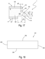
- Figure 17 shows a panel edge comprising a groove-tongue profile as in this aspect.
- the groove - tongue profile is similar to the groove - tongue profile 1 shown in figure 3 ; the reference numbers in figure 17 have the same meaning as in figure 3 .
- the panel of the example of figure 17 comprises three layers of wood 125, 126, 127.
- the layers of wood comprise a first layer of wood 125, a second layer 126 of wood and a third layer 127 of wood.
- the second layer of wood is provided between the first layer of wood and the third layer of wood.
- the continuous tongue 104 of the first groove - tongue profile 1 is provided in the second layer 126 of wood.
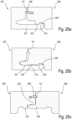
- Figures 18 - 20 illustrate embodiments of panels according to the invention.
- Figures 21 to 27 illustrate embodiments of panels not according to the invention, but comprising features of the invention.
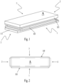
- Figure 18 shows a panel 201.
- the panel 201 is rectangular, square or oblong.
- the panel comprises a first edge 202 and a third edge 204.
- the first edge and the third edges are provided opposite to each other.
- the panel comprises a second edge 203 and a fourth edge 205, wherein the second edge and the fourth edge are provided opposite to each other.
- Each of the first edge, the second edge, the third edge and the fourth edge comprise a profile selected from a first profile, a second profile and a third profile. Both short edges can e.g. be provided with the second profile.
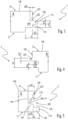
- the first profile 207, the second profile 208 and the third profile 209 are configured such that a panel edge comprising the first profile can be coupled to the edge of another such panel wherein the edge of the another such panel comprises any one of the second profile or the third profile, wherein in the coupled condition a locking of the coupled edges is provided in the direction perpendicular to the coupled panels as well as in the direction perpendicular to the coupled edges and parallel with the surface of the coupled panels; and such that a panel edge comprising the second profile can be coupled to the edge of another such panel wherein the edge of the another such panel comprises the third profile, wherein in the coupled condition a locking of the coupled edges is provided in the direction perpendicular to the coupled panels as well as in the direction perpendicular to the coupled edges and parallel with the surface of the coupled panels.
- each of the first profile 207, the second profile 208 and the third profile 209 extend continuously and without interruption along the edge(s) where they are provided.
- each of the first profile 207, the second profile 208 and the third profile 209 have a constant cross section perpendicularly to the edge where they are provided, over the full length of the edge where they are provided.
- each of the first profile 207, the second profile 208 and the third profile 209 extend along the full length of the panel edge(s) where they are provided.
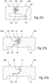
- Figures 20a-c show the edge profiles of figures 19a-c in coupled condition.
- Figures 22a-c show the edge profiles of figures 21a-c in coupled condition.
- Figures 24a-c show the edge profiles of figures 23a-c in coupled condition.
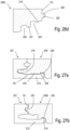
- the locking surface 215 is provided for establishing a locking in the direction perpendicular to the panel surface when a panel edge comprising the first profile is coupled to the edge of another such panel when said edge of the another such panel comprises the third profile.
- the second tongue 222 comprises a locking surface 225 for establishing a locking in the direction perpendicular to the surface of the panels in combination with the locking surface of the first profile or the locking surface of the second profile, when a panel edge comprising the third profile is coupled to an edge of another such panel comprising the first profile respectively the second profile.
- the first tongue 221 or the second tongue 222 comprises a locking element 219, which is provided for establishing in combination with the second recess 218 of the second profile a locking in the direction perpendicular to the coupled edges and parallel with the panel surface when a panel edge comprising the third profile is coupled to the edge comprising the second profile of another such panel.
- each of the first edge, the second edge, the third edge and the fourth edge are provided closer to the panel surface than the first profile, the second profile and the third profile with a closing plane 101.
- the closing planes 101 are provided perpendicularly to the panel surface. In coupled condition of two panels the closing planes of the panel edges coupled to each other contact each other or are positioned closely to each other.
- the locking surface 215 of the upper lip 215 of the first profile is provided at the upper surface of an additional groove 226 closer to the panel surface than the groove 211 of the first profile.
- the locking surface 215 of the upper lip 213 of the first profile 207 is provided as an inclined surface at the distal edge of the upper lip.
- an upper surface of the second tongue 222 provides the locking surface 225 of the third profile.
- the locking surface 225 of the second tongue 222 is provided by a separate insert 228 inserted in the second tongue 222.
- a displacement of the locking surface 225 - caused by a displacement or deformation (e.g. an elastic deformation) of at least part of the insert 228 during the coupling of the panel edges provides for the locking in the direction perpendicular to the surface of the panel
- Figure 23c shows an example of insert 228 that can be used.
- Figures 25 show another example of an insert 228 that can be used, which provided the coupling by a sliding movement of at least part of the insert.
- the panel example of figure 18 is described can e.g. at both short edges 203, 205 comprise the second profile 208.
- Two edges comprising the same profile selected from the first profile, the second profile and the third profile, can comprise profiles selected from the first profile or the second profile or the third profile that differ in cross section perpendicular to the panel edge where the profiles are provided. Examples of such embodiments are illustrated in figures 26 - 28 .
- the reference numbers in figures 26 - 28 have the same meaning as in the figures 19 - 25 .
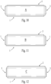
- Figure 26a-d show an example of the profiles at the four edges of a rectangular and oblong panel.
- Figures 27a-e show the edge profiles in coupled condition of the profile edges shown in figure 26 .
- Figure 28a-e show the edge profiles in coupled condition of another such embodiment.
- Figures 26a-d illustrate the four profiles, one provided at each of the four panel edges of a rectangular and oblong panel.
- the first profile 207 is provided at one of the panel edges.
- the first profile 207 shown in figure 26a corresponds to a large extent to the first profile shown in figure 19a .
- the second profile 208 shown in figure 26b is provided at one of the panel edges.
- Two - preferably opposite - panel edges are each provided with a different configuration of a third profile 209a, 209b.
- the two configurations of the third profile 209a, 209b differ in cross section perpendicular to the panel edge where the profiles are provided.
- the locking surface of the second tongue 222 is provided by a separate insert 225 inserted in the second tongue.
- the insert is elastically deformable such that the coupling with locking of the coupled edges in the direction perpendicular to the panel surface can be realized.
- an upper surface of the second tongue 222 provides the locking surface 225 of the third profile 209b.
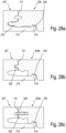
- Figures 28 show - in coupled condition - an alternative for the embodiment shown in figures 26 and 27 .
- the profiles (the first profile 207, the second profile 208, and both third profiles 209a, 209b) are to a large extent similar to the ones shown is figures 26 and 27 , major difference being the different type of insert 228 being inserted in the first configuration of the third profile 209a.
- the locking is obtained via a sliding movement of the locking surface 225 during coupling.
- an elastic movement during the coupling of the related panel edges is possible of at least part of the insert 228 in the slot in the second tongue 222 in which the inert 228 is provided.
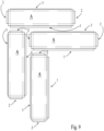
- the panels of the invention can be installed in laying patterns wherein the panels are coupled to each other under a 90° angle, e.g. as in the herringbone configuration shown in figure 9 .
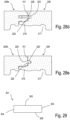
- Figure 29 shows a panel 301.
- the panel 301 is rectangular and oblong.
- the panel 301 comprises a first edge 302, a second edge 303, a third edge 304, and a fourth edge 305.
- the first and the fourth edge are provided at the long edges of the panel and the second and the third edge are provided at the short edges of the panel.
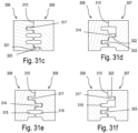
- Figures 30a-d show an example of the coupling profiles of the panel shown in figure 29 .
- the first edge 302 of the panel of figure 29 is provided with a first coupling profile 306 shown in figure 30a .
- the second edge 303 is provided with a second coupling profile 307 shown in figure 30b .
- the third edge 304 is provided with a third coupling profile 308 shown in figure 30c .
- the fourth edge 305 is provided with a fourth coupling profile 309 shown in figure 30d .
- Each of the first coupling profile 306, the second coupling profile 307, the third coupling profile 308 and the fourth coupling profile 309 extend along the full length of the panel edge where they are provided.
- Each of the first coupling profile 306, the second coupling profile 307, the third coupling profile 308 and the fourth coupling profile 309 have along the length of the panel edge where they are provided a constant cross section perpendicular to the panel edge where they are provided.
- Each of the first coupling profile 306, the second coupling profile 307, the third coupling profile 308 and the fourth coupling 309 profile extend continuously along the edge where they are provided.
Landscapes
- Engineering & Computer Science (AREA)
- Architecture (AREA)
- Civil Engineering (AREA)
- Structural Engineering (AREA)
- Finishing Walls (AREA)
Claims (12)
- Paneel, wobei das Paneel (201) rechteckig, quadratisch oder länglich ist;wobei das Paneel eine erste Kante (202) und eine dritte Kante (204) umfasst, wobei die erste Kante und die dritte Kante einander gegenüberliegend vorgesehen sind;wobei das Paneel eine zweite Kante (203) und eine vierte Kante (205) umfasst,wobei die zweite Kante und die vierte Kante einander gegenüberliegend vorgesehen sind;wobei jede Kante der ersten Kante, der zweiten Kante, der dritten Kante und der vierten Kante ein Profil umfasst, das aus einem ersten Profil (207), einem zweiten Profil (208) und einem dritten Profil (209) ausgewählt wird;wobei das erste Profil, das zweite Profil und das dritte Profil so ausgebildet sind, dass eine Kante des Paneels, die das erste Profil umfasst, mit der Kante eines anderen solchen Paneels gekoppelt werden kann;wobei die Kante des anderen solchen Paneels eines der Profile umfasst, das aus dem zweiten Profil oder dem dritten Profil ausgewählt ist; wobei in dem gekoppelten Zustand eine Verriegelung der gekoppelten Kanten in der Richtung senkrecht zu den gekoppelten Paneelen sowie in der Richtung senkrecht zu den gekoppelten Kanten und parallel zu der Oberfläche der gekoppelten Kanten bereitgestellt wird;und so, dass eine Kante des Paneels, das das zweite Profil umfasst, mit der Kante eines anderen Paneels dieses Typs gekoppelt werden kann; wobei die Kante des anderen Paneels dieses Typs das dritte Profil umfasst;wobei in dem gekoppelten Zustand eine Verriegelung der gekoppelten Kanten in der Richtung senkrecht zu den gekoppelten Paneelen sowie in der Richtung senkrecht zu den gekoppelten Kanten und parallel zu der Oberfläche der gekoppelten Paneele bereitgestellt wird;wobei das erste Profil (207) eine Nut (211) umfasst; wobei die Nut durch eine untere Lippe (212) und durch eine obere Lippe (213) begrenzt ist; wobei die untere Lippe sich in distaler Richtung bis über die obere Lippe hinaus erstreckt;wobei die untere Lippe ein Verriegelungselement (214) umfasst, vorzugsweise an ihrem distalen Ende;wobei das Verriegelungselement bereitgestellt wird, um eine Verriegelung in der Richtung senkrecht zu den gekoppelten Kanten und parallel zu der Oberfläche des Paneels zu bewirken, wenn eine Kante des Paneels, das das erste Profil (207) umfasst, mit der Kante eines anderen solchen Paneels gekoppelt wird, wenn die oben genannte Kante des anderen Paneel dieses Typs eines der Profile umfasst, das aus dem zweiten Profil (208) oder dem dritten Profil (209) ausgewählt wird;wobei die obere Lippe (213) eine Verriegelungsfläche (215) umfasst - wobei vorzugsweise die Verriegelungsfläche parallel zu der Oberfläche des Paneels oder in Bezug auf diese geneigt ist - mit dem Zweck, eine Verriegelung in der Richtung senkrecht zu der Oberfläche des Paneels herzustellen, wenn eine Kante des Paneels, das das erste Profil umfasst, mit der Kante eines anderen Paneels dieses Typs gekoppelt wird, wenn die oben genannte Kante des anderen Paneels dieses Typs das dritte Profil umfasst;wobei das zweite Profil (208) eine Feder (216) umfasst; wobei die Feder zum Einführen in die Nut (211) des ersten Profils (207) einer Kante eines weiteren Paneels dieser Art ausgebildet ist, um dadurch eine Verriegelung in der Richtung senkrecht zu der Oberfläche der so gekoppelten Paneele herzustellen;wobei die Feder (216) eine erste Aussparung (217) umfasst; wobei die erste Aussparung für das Zusammenwirken mit dem Verriegelungselement (214) des ersten Profils (207) einer Kante eines weiteren solchen Paneels geeignet ist, um dadurch eine Verriegelung der so gekoppelten Paneele in der Richtung senkrecht zu den verbundenen Kanten und parallel zu der Oberfläche des Paneels herzustellen;wobei die Feder (216) eine zweite Aussparung (218) umfasst; wobei die zweite Aussparung geeignet ist, mit einem Verriegelungselement (219) des dritten Profils (209) einer Kante eines weiteren solchen Paneels zusammenzuwirken, um dadurch eine Verriegelung der so gekoppelten Paneele in der Richtung senkrecht zu den gekoppelten Kanten und parallel zu der Oberfläche des Paneels herzustellen;wobei das zweite Profil (208) näher an der Oberfläche des Paneels als die von der Feder (216) eingenommene Stelle eine Verriegelungsfläche (220) umfasst - wobei vorzugsweise die Verriegelungsfläche parallel zu der Oberfläche des Paneels oder in Bezug auf diese geneigt ist - mit dem Ziel, eine Verriegelung in der Richtung senkrecht zu der Oberfläche des Paneels herzustellen, wenn eine Kante des Paneels, das das zweite Profil umfasst, mit der Kante eines anderen Paneels dieses Typs gekoppelt wird, wenn die oben genannte Kante des anderen Paneels dieses Typs das dritte Profil (209) umfasst;wobei das dritte Profil (209) eine erste Feder (221) und eine zweite Feder (222) umfasst;wobei die zweite Feder (222) näher an der Oberfläche des Paneels vorgesehen ist als die erste Feder (221);wobei eine zweite Nut (223) zwischen der ersten Feder und der zweiten Feder vorgesehen ist;wobei die erste Feder an ihrer Basis eine Aussparung (224) umfasst; wobei die Aussparung dazu vorgesehen ist, in Zusammenwirkung mit dem Verriegelungselement (214) der unteren Lippe des ersten Profils eine Verriegelung in der Richtung senkrecht zu den gekoppelten Kanten und parallel zu der Oberfläche des Paneels herzustellen, wenn eine Kante des Paneels, die das dritte Profil umfasst, mit der Kante, die das erste Profil umfasst, eines anderen solchen Paneels gekoppelt wird;wobei die zweite Feder (222) eine Verriegelungsfläche (225) umfasst, die dazu bestimmt ist, in der Richtung senkrecht zu der Oberfläche der Paneele in Kombination mit der Verriegelungsfläche des ersten Profils oder mit der Verriegelungsfläche des zweiten Profils eine Verriegelung herzustellen, wenn eine Kante des Paneels, das das dritte Profil umfasst, mit einer Kante eines anderen Paneels dieses Typs gekoppelt ist, das das erste Profil bzw. das zweite Profil umfasst; wobei die erste Feder (221) oder die zweite Feder (222) das Verriegelungselement (219) umfasst; wobei das Verriegelungselement dazu vorgesehen ist, in Kombination mit der zweiten Aussparung (218) des zweiten Profils eine Verriegelung in der Richtung senkrecht zu den gekoppelten Kanten und parallel zu der Oberfläche des Paneels herzustellen, wenn eine Kante des Paneels, die das dritte Profil umfasst, mit der Kante, die das zweite Profil umfasst, eines anderen solchen Paneels gekoppelt wird;dadurch gekennzeichnet, dass die erste Aussparung (217) und die zweite Aussparung (218) auf derselben Seite der Feder (216) vorgesehen sind; wobei vorzugsweise die erste Aussparung und die zweite Aussparung an der Basis der Feder vorgesehen sind.
- Paneel nach Anspruch 1, wobei das Verriegelungselement (214) der unteren Lippe (212) des ersten Profils (207) nach oben gerichtet ist.
- Paneel nach einem der vorstehenden Ansprüche 1 bis 2, wobei die Verriegelungsfläche (215) der oberen Lippe (213) des ersten Profils auf der oberen Seite einer weiteren Nut (226) vorgesehen ist, die näher an der Oberfläche des Paneels liegt als die Nut (211) des ersten Profils.
- Paneel nach einem der Ansprüche 1 bis 2, wobei die Verriegelungsfläche (215) der oberen Lippe (213) des ersten Profils in der Form einer geneigten Fläche an der distalen Kante der oberen Lippe vorgesehen ist.
- Paneel nach einem der Ansprüche 1 bis 4, wobei die Verriegelungsfläche (220) des zweiten Profils (208) auf der oberen Seite eines Hinterschnitts (227) in dem zweiten Profil vorgesehen ist.
- Paneel nach einem der Ansprüche 1 bis 5, wobei eine obere Fläche der zweiten Feder (222) die Verriegelungsfläche (225) des dritten Profils bereitstellt.
- Paneel nach einem der Ansprüche 1 bis 5, wobei die Verriegelungsfläche (225) der zweiten Feder (222) durch einen separaten Einsatz (228) bereitgestellt wird, der in die zweite Feder (222) eingesetzt ist; wobei der Einsatz (228) so ausgebildet ist, dass die Bewegung der Verriegelungsfläche (225) durch eine Bewegung oder Verformung - vorzugsweise elastisch - von mindestens einem Teil des Einsatzes (228) während des Kuppelns der Kanten der Paneele die oben genannte Verriegelung in der Richtung senkrecht zur Oberfläche des Paneels bereitstellt.
- Paneel nach einem jeden der Ansprüche 1 bis 7, wobei in dem gekoppelten Zustand einer Kante, die das erste Profil (207) umfasst, mit einer Kante, die das zweite Profil (208) eines anderen Paneels dieses Typs umfasst, ein freier Raum (229) zwischen der oberen Fläche des Verriegelungselements (214) des ersten Profils und der Kante des anderen Paneels vorgesehen ist.
- Paneel nach einem der Ansprüche 1 bis 8, wobei in dem gekoppelten Zustand einer Kante, die das erste Profil (207) umfasst, mit einer Kante, die das dritte Profil (209) eines anderen Paneels dieses Typs umfasst, ein freier Raum (230) zwischen der oberen Fläche des Verriegelungselements (214) des ersten Profils und der Kante des anderen Paneels vorgesehen ist.
- Paneel nach einem der Ansprüche 1 bis 9, wobei in dem gekoppelten Zustand einer Kante, die das erste Profil (207) umfasst, mit einer Kante, die das zweite Profil (208) eines anderen Paneels dieses Typs umfasst, die untere Lippe (212) des ersten Profils in zwei getrennten Bereichen (231, 232) mit dem zweiten Profil (208) der Kante des anderen Paneels dieses Typs in Kontakt kommt; wobei ein freier Raum (233) zwischen den oben genannten zwei getrennten Bereichen vorhanden ist.
- Paneel nach einem der Ansprüche 1 bis 10, wobei in dem gekoppelten Zustand einer Kante, die das erste Profil (207) umfasst, mit einer Kante, die das dritte Profil (209) eines anderen Paneels dieses Typs umfasst, die untere Lippe (212) des ersten Profils in zwei getrennten Bereichen (234, 235) mit der Basis der ersten Feder des zweiten Profils der Kante des anderen Paneels dieses Typs in Kontakt kommt, wobei zwischen den oben genannten zwei getrennten Bereichen ein freier Raum (236) vorgesehen ist.
- Paneel nach einem der Ansprüche 1 bis 11, wobei das Paneel eine längliche Form aufweist; und wobei die beiden kurzen Seiten (203, 205) mit demselben Profil versehen sind; wobei vorzugsweise die beiden kurzen Seiten (203, 205) mit dem zweiten Profil (208) versehen sind.
Applications Claiming Priority (4)
| Application Number | Priority Date | Filing Date | Title |
|---|---|---|---|
| EP20173023.1A EP3907346B1 (de) | 2020-05-05 | 2020-05-05 | Mehrprofilpaneel |
| DE202020102526.0U DE202020102526U1 (de) | 2020-05-05 | 2020-05-05 | Mehrprofilpaneel |
| PCT/IB2021/053774 WO2021224810A1 (en) | 2020-05-05 | 2021-05-05 | Panel |
| EP21724042.3A EP4146879A1 (de) | 2020-05-05 | 2021-05-05 | Paneel |
Related Parent Applications (1)
| Application Number | Title | Priority Date | Filing Date |
|---|---|---|---|
| EP21724042.3A Division EP4146879A1 (de) | 2020-05-05 | 2021-05-05 | Paneel |
Publications (2)
| Publication Number | Publication Date |
|---|---|
| EP4257775A1 EP4257775A1 (de) | 2023-10-11 |
| EP4257775B1 true EP4257775B1 (de) | 2025-07-09 |
Family
ID=75850412
Family Applications (2)
| Application Number | Title | Priority Date | Filing Date |
|---|---|---|---|
| EP23194434.9A Active EP4257775B1 (de) | 2020-05-05 | 2021-05-05 | Paneel |
| EP21724042.3A Pending EP4146879A1 (de) | 2020-05-05 | 2021-05-05 | Paneel |
Family Applications After (1)
| Application Number | Title | Priority Date | Filing Date |
|---|---|---|---|
| EP21724042.3A Pending EP4146879A1 (de) | 2020-05-05 | 2021-05-05 | Paneel |
Country Status (4)
| Country | Link |
|---|---|
| US (1) | US20230160217A1 (de) |
| EP (2) | EP4257775B1 (de) |
| PL (1) | PL4257775T3 (de) |
| WO (1) | WO2021224810A1 (de) |
Families Citing this family (3)
| Publication number | Priority date | Publication date | Assignee | Title |
|---|---|---|---|---|
| EP4086408B1 (de) * | 2021-05-05 | 2024-10-16 | Bart Oerlemans BV | Paneel |
| FR3139586A1 (fr) * | 2022-09-09 | 2024-03-15 | Inovame | Lame rectangulaire mince de revêtement destinée à la pose en bâton rompu |
| WO2025088483A1 (en) | 2023-10-27 | 2025-05-01 | Unilin, Bv | Covering comprising panels |
Family Cites Families (26)
| Publication number | Priority date | Publication date | Assignee | Title |
|---|---|---|---|---|
| US1787027A (en) | 1929-02-20 | 1930-12-30 | Wasleff Alex | Herringbone flooring |
| US2187672A (en) | 1934-09-27 | 1940-01-16 | Axel G W Wedberg | Three ply flooring |
| US6421970B1 (en) * | 1995-03-07 | 2002-07-23 | Perstorp Flooring Ab | Flooring panel or wall panel and use thereof |
| SE9500810D0 (sv) * | 1995-03-07 | 1995-03-07 | Perstorp Flooring Ab | Golvplatta |
| SE506254C2 (sv) | 1997-02-26 | 1997-11-24 | Tarkett Ab | Parkettgolvsstav för att bilda ett golv med fiskbensmönster |
| US6823638B2 (en) * | 2001-06-27 | 2004-11-30 | Pergo (Europe) Ab | High friction joint, and interlocking joints for forming a generally planar surface, and method of assembling the same |
| DE10206877B4 (de) * | 2002-02-18 | 2004-02-05 | E.F.P. Floor Products Fussböden GmbH | Paneel, insbesondere Fussbodenpaneel |
| DE20208058U1 (de) | 2002-05-23 | 2002-08-22 | Cernay, Markus, Dipl.-Ing., 80803 München | Laminat |
| DE20304761U1 (de) * | 2003-03-24 | 2004-04-08 | Kronotec Ag | Einrichtung zum Verbinden von Bauplatten, insbesondere Bodenpaneele |
| DE20313661U1 (de) * | 2003-09-05 | 2003-11-13 | Kronospan Technical Co. Ltd., Nikosia | Paneel mit geschützter V-Fuge |
| DE102004028757B4 (de) | 2004-04-02 | 2007-11-15 | hülsta-werke Hüls GmbH & Co. KG. | Paneelelement zur Boden-, Wand- und/oder Deckenverlegung sowie Verfahren zum Verlegen eines Belages, insbesondere eines Boden-, Wand- und/oder Deckenbelages |
| US20050247000A1 (en) * | 2004-05-04 | 2005-11-10 | Zhu Sai Y | Interlocking self-aligning cladding panel for floors, walls, ceilings, or the like |
| US7854100B2 (en) * | 2006-01-12 | 2010-12-21 | Valinge Innovation Ab | Laminate floor panels |
| BE1017350A6 (nl) * | 2006-10-31 | 2008-06-03 | Flooring Ind Ltd | Vloerpaneel en vloerbekleding bestaande uit dergelijke vloerpanelen. |
| DE102006057491A1 (de) * | 2006-12-06 | 2008-06-12 | Akzenta Paneele + Profile Gmbh | Paneel sowie Bodenbelag |
| US8353140B2 (en) * | 2007-11-07 | 2013-01-15 | Valinge Innovation Ab | Mechanical locking of floor panels with vertical snap folding |
| CA2623707A1 (en) * | 2008-03-07 | 2009-09-07 | Pierre Trudel | Tongue and groove profile to ease desassembly of floorboards |
| DE202008011589U1 (de) * | 2008-09-01 | 2008-11-27 | Akzenta Paneele + Profile Gmbh | Fußbodenpaneel aus Kunststoff mit mechanischen Verriegelungskanten |
| DE102010004717A1 (de) * | 2010-01-15 | 2011-07-21 | Pergo (Europe) Ab | Set aus Paneelen umfassend Halteprofile mit einem separaten Clip sowie Verfahren zum Einbringen des Clips |
| BE1021833B1 (nl) * | 2013-05-30 | 2016-01-21 | Flooring Industries Limited Sarl | Paneel |
| EP3128102B1 (de) | 2015-08-06 | 2018-03-21 | Beugt Houtzagerij en Parketindustrie BV | Paneel für holzboden mit einem muster |
| BE1024157B1 (nl) * | 2016-04-25 | 2017-11-24 | Flooring Industries Limited, Sarl | Set van vloerpanelen en werkwijze voor het installeren van deze set van vloerpanelen. |
| PL3447210T3 (pl) * | 2017-08-23 | 2021-11-15 | Flooring Industries Limited, Sarl | Panele podłogowe do tworzenia pokrycia podłogowego |
| EP4234837B1 (de) * | 2018-01-09 | 2026-02-04 | Välinge Innovation AB | Paneelsatz |
| EP3581732B1 (de) * | 2018-06-15 | 2022-12-07 | Akzenta Paneele + Profile GmbH | Paneel mit dichtungsrille und dichtungsleiste |
| BE1026806B1 (nl) * | 2018-11-27 | 2020-06-30 | Flooring Ind Ltd Sarl | Paneel en werkwijze voor het vervaardigen van dergelijk paneel |
-
2021
- 2021-05-05 EP EP23194434.9A patent/EP4257775B1/de active Active
- 2021-05-05 US US17/922,893 patent/US20230160217A1/en active Pending
- 2021-05-05 PL PL23194434.9T patent/PL4257775T3/pl unknown
- 2021-05-05 EP EP21724042.3A patent/EP4146879A1/de active Pending
- 2021-05-05 WO PCT/IB2021/053774 patent/WO2021224810A1/en not_active Ceased
Also Published As
| Publication number | Publication date |
|---|---|
| US20230160217A1 (en) | 2023-05-25 |
| WO2021224810A1 (en) | 2021-11-11 |
| EP4146879A1 (de) | 2023-03-15 |
| PL4257775T3 (pl) | 2025-10-06 |
| EP4257775A1 (de) | 2023-10-11 |
Similar Documents
| Publication | Publication Date | Title |
|---|---|---|
| EP4257775B1 (de) | Paneel | |
| US12077968B2 (en) | Mechanical locking system for floor panels | |
| CN114786531B (zh) | 具有机械锁定装置的成组镶板 | |
| CA2785051C (en) | Method for connecting and interlocking panels | |
| US11591807B2 (en) | Floor panel for forming a floor covering | |
| CN102943555B (zh) | 与地板镶板的机械锁定和拆装相关的方法、设备和产品 | |
| US9347227B2 (en) | Floating floor system, floor panel, and installation method for the same | |
| KR102314032B1 (ko) | 플로어 패널을 위한 기계적 잠금 시스템 | |
| EP3730719B1 (de) | Mechanisches arretierungssystem für bodenplatten | |
| EP4069917A1 (de) | Bodenplatte zur formung eines bodenbelags | |
| EP3839170B1 (de) | Bodenplatte zur formung eines bodenbelags und verfahren zur herstellung einer bodenplatte | |
| CN112709400A (zh) | 用于地板镶板的机械锁定系统 | |
| CA2656920A1 (en) | Locking system comprising a combination lock for panels | |
| US12559942B2 (en) | Self-spacing lap and panel siding | |
| EP4334547B1 (de) | Paneel | |
| EP4517025A2 (de) | Paneel und bodenbelag damit | |
| RU2372455C2 (ru) | Профилированная панель | |
| US12595666B2 (en) | Panel | |
| EP4127355B1 (de) | Paneel |
Legal Events
| Date | Code | Title | Description |
|---|---|---|---|
| PUAI | Public reference made under article 153(3) epc to a published international application that has entered the european phase |
Free format text: ORIGINAL CODE: 0009012 |
|
| STAA | Information on the status of an ep patent application or granted ep patent |
Free format text: STATUS: THE APPLICATION HAS BEEN PUBLISHED |
|
| AC | Divisional application: reference to earlier application |
Ref document number: 4146879 Country of ref document: EP Kind code of ref document: P |
|
| AK | Designated contracting states |
Kind code of ref document: A1 Designated state(s): AL AT BE BG CH CY CZ DE DK EE ES FI FR GB GR HR HU IE IS IT LI LT LU LV MC MK MT NL NO PL PT RO RS SE SI SK SM TR |
|
| STAA | Information on the status of an ep patent application or granted ep patent |
Free format text: STATUS: REQUEST FOR EXAMINATION WAS MADE |
|
| 17P | Request for examination filed |
Effective date: 20240328 |
|
| RBV | Designated contracting states (corrected) |
Designated state(s): AL AT BE BG CH CY CZ DE DK EE ES FI FR GB GR HR HU IE IS IT LI LT LU LV MC MK MT NL NO PL PT RO RS SE SI SK SM TR |
|
| GRAP | Despatch of communication of intention to grant a patent |
Free format text: ORIGINAL CODE: EPIDOSNIGR1 |
|
| STAA | Information on the status of an ep patent application or granted ep patent |
Free format text: STATUS: GRANT OF PATENT IS INTENDED |
|
| INTG | Intention to grant announced |
Effective date: 20250204 |
|
| GRAS | Grant fee paid |
Free format text: ORIGINAL CODE: EPIDOSNIGR3 |
|
| GRAA | (expected) grant |
Free format text: ORIGINAL CODE: 0009210 |
|
| STAA | Information on the status of an ep patent application or granted ep patent |
Free format text: STATUS: THE PATENT HAS BEEN GRANTED |
|
| AC | Divisional application: reference to earlier application |
Ref document number: 4146879 Country of ref document: EP Kind code of ref document: P |
|
| AK | Designated contracting states |
Kind code of ref document: B1 Designated state(s): AL AT BE BG CH CY CZ DE DK EE ES FI FR GB GR HR HU IE IS IT LI LT LU LV MC MK MT NL NO PL PT RO RS SE SI SK SM TR |
|
| P01 | Opt-out of the competence of the unified patent court (upc) registered |
Free format text: CASE NUMBER: APP_25926/2025 Effective date: 20250602 |
|
| REG | Reference to a national code |
Ref country code: GB Ref legal event code: FG4D |
|
| REG | Reference to a national code |
Ref country code: CH Ref legal event code: EP |
|
| REG | Reference to a national code |
Ref country code: IE Ref legal event code: FG4D |
|
| REG | Reference to a national code |
Ref country code: DE Ref legal event code: R096 Ref document number: 602021034020 Country of ref document: DE |
|
| REG | Reference to a national code |
Ref country code: NL Ref legal event code: FP |
|
| PG25 | Lapsed in a contracting state [announced via postgrant information from national office to epo] |
Ref country code: PT Free format text: LAPSE BECAUSE OF FAILURE TO SUBMIT A TRANSLATION OF THE DESCRIPTION OR TO PAY THE FEE WITHIN THE PRESCRIBED TIME-LIMIT Effective date: 20251110 |
|
| PG25 | Lapsed in a contracting state [announced via postgrant information from national office to epo] |
Ref country code: IS Free format text: LAPSE BECAUSE OF FAILURE TO SUBMIT A TRANSLATION OF THE DESCRIPTION OR TO PAY THE FEE WITHIN THE PRESCRIBED TIME-LIMIT Effective date: 20251109 |
|
| PG25 | Lapsed in a contracting state [announced via postgrant information from national office to epo] |
Ref country code: NO Free format text: LAPSE BECAUSE OF FAILURE TO SUBMIT A TRANSLATION OF THE DESCRIPTION OR TO PAY THE FEE WITHIN THE PRESCRIBED TIME-LIMIT Effective date: 20251009 |
|
| REG | Reference to a national code |
Ref country code: LT Ref legal event code: MG9D |
|
| PG25 | Lapsed in a contracting state [announced via postgrant information from national office to epo] |
Ref country code: FI Free format text: LAPSE BECAUSE OF FAILURE TO SUBMIT A TRANSLATION OF THE DESCRIPTION OR TO PAY THE FEE WITHIN THE PRESCRIBED TIME-LIMIT Effective date: 20250709 |
|
| PG25 | Lapsed in a contracting state [announced via postgrant information from national office to epo] |
Ref country code: HR Free format text: LAPSE BECAUSE OF FAILURE TO SUBMIT A TRANSLATION OF THE DESCRIPTION OR TO PAY THE FEE WITHIN THE PRESCRIBED TIME-LIMIT Effective date: 20250709 |
|
| PG25 | Lapsed in a contracting state [announced via postgrant information from national office to epo] |
Ref country code: GR Free format text: LAPSE BECAUSE OF FAILURE TO SUBMIT A TRANSLATION OF THE DESCRIPTION OR TO PAY THE FEE WITHIN THE PRESCRIBED TIME-LIMIT Effective date: 20251010 |
|
| PG25 | Lapsed in a contracting state [announced via postgrant information from national office to epo] |
Ref country code: SE Free format text: LAPSE BECAUSE OF FAILURE TO SUBMIT A TRANSLATION OF THE DESCRIPTION OR TO PAY THE FEE WITHIN THE PRESCRIBED TIME-LIMIT Effective date: 20250709 |
|
| PG25 | Lapsed in a contracting state [announced via postgrant information from national office to epo] |
Ref country code: LV Free format text: LAPSE BECAUSE OF FAILURE TO SUBMIT A TRANSLATION OF THE DESCRIPTION OR TO PAY THE FEE WITHIN THE PRESCRIBED TIME-LIMIT Effective date: 20250709 |
|
| PG25 | Lapsed in a contracting state [announced via postgrant information from national office to epo] |
Ref country code: BG Free format text: LAPSE BECAUSE OF FAILURE TO SUBMIT A TRANSLATION OF THE DESCRIPTION OR TO PAY THE FEE WITHIN THE PRESCRIBED TIME-LIMIT Effective date: 20250709 |
|
| PG25 | Lapsed in a contracting state [announced via postgrant information from national office to epo] |
Ref country code: RS Free format text: LAPSE BECAUSE OF FAILURE TO SUBMIT A TRANSLATION OF THE DESCRIPTION OR TO PAY THE FEE WITHIN THE PRESCRIBED TIME-LIMIT Effective date: 20251009 |
|
| PG25 | Lapsed in a contracting state [announced via postgrant information from national office to epo] |
Ref country code: ES Free format text: LAPSE BECAUSE OF FAILURE TO SUBMIT A TRANSLATION OF THE DESCRIPTION OR TO PAY THE FEE WITHIN THE PRESCRIBED TIME-LIMIT Effective date: 20250709 |