EP4256358B1 - Rauscharmes squid-basiertes rf-detektions- und erfassungssystem und ausrüstung mit diesem system - Google Patents
Rauscharmes squid-basiertes rf-detektions- und erfassungssystem und ausrüstung mit diesem system Download PDFInfo
- Publication number
- EP4256358B1 EP4256358B1 EP21848262.8A EP21848262A EP4256358B1 EP 4256358 B1 EP4256358 B1 EP 4256358B1 EP 21848262 A EP21848262 A EP 21848262A EP 4256358 B1 EP4256358 B1 EP 4256358B1
- Authority
- EP
- European Patent Office
- Prior art keywords
- detection
- squid
- antenna
- flux
- acquisition system
- Prior art date
- Legal status (The legal status is an assumption and is not a legal conclusion. Google has not performed a legal analysis and makes no representation as to the accuracy of the status listed.)
- Active
Links
Images

Classifications
-
- G—PHYSICS
- G01—MEASURING; TESTING
- G01R—MEASURING ELECTRIC VARIABLES; MEASURING MAGNETIC VARIABLES
- G01R33/00—Arrangements or instruments for measuring magnetic variables
- G01R33/20—Arrangements or instruments for measuring magnetic variables involving magnetic resonance
- G01R33/28—Details of apparatus provided for in groups G01R33/44 - G01R33/64
- G01R33/32—Excitation or detection systems, e.g. using radio frequency signals
- G01R33/323—Detection of MR without the use of RF or microwaves, e.g. force-detected MR, thermally detected MR, MR detection via electrical conductivity, optically detected MR
- G01R33/326—Detection of MR without the use of RF or microwaves, e.g. force-detected MR, thermally detected MR, MR detection via electrical conductivity, optically detected MR involving a SQUID
-
- A—HUMAN NECESSITIES
- A61—MEDICAL OR VETERINARY SCIENCE; HYGIENE
- A61B—DIAGNOSIS; SURGERY; IDENTIFICATION
- A61B5/00—Measuring for diagnostic purposes; Identification of persons
- A61B5/05—Detecting, measuring or recording for diagnosis by means of electric currents or magnetic fields; Measuring using microwaves or radio waves
-
- A—HUMAN NECESSITIES
- A61—MEDICAL OR VETERINARY SCIENCE; HYGIENE
- A61B—DIAGNOSIS; SURGERY; IDENTIFICATION
- A61B5/00—Measuring for diagnostic purposes; Identification of persons
- A61B5/24—Detecting, measuring or recording bioelectric or biomagnetic signals of the body or parts thereof
- A61B5/242—Detecting biomagnetic fields, e.g. magnetic fields produced by bioelectric currents
- A61B5/245—Detecting biomagnetic fields, e.g. magnetic fields produced by bioelectric currents specially adapted for magnetoencephalographic [MEG] signals
-
- G—PHYSICS
- G01—MEASURING; TESTING
- G01R—MEASURING ELECTRIC VARIABLES; MEASURING MAGNETIC VARIABLES
- G01R33/00—Arrangements or instruments for measuring magnetic variables
- G01R33/20—Arrangements or instruments for measuring magnetic variables involving magnetic resonance
- G01R33/28—Details of apparatus provided for in groups G01R33/44 - G01R33/64
- G01R33/32—Excitation or detection systems, e.g. using radio frequency signals
- G01R33/34—Constructional details, e.g. resonators, specially adapted to MR
-
- G—PHYSICS
- G01—MEASURING; TESTING
- G01R—MEASURING ELECTRIC VARIABLES; MEASURING MAGNETIC VARIABLES
- G01R33/00—Arrangements or instruments for measuring magnetic variables
- G01R33/20—Arrangements or instruments for measuring magnetic variables involving magnetic resonance
- G01R33/28—Details of apparatus provided for in groups G01R33/44 - G01R33/64
- G01R33/32—Excitation or detection systems, e.g. using radio frequency signals
- G01R33/34—Constructional details, e.g. resonators, specially adapted to MR
- G01R33/34046—Volume type coils, e.g. bird-cage coils; Quadrature bird-cage coils; Circularly polarised coils
- G01R33/34061—Helmholtz coils
-
- G—PHYSICS
- G01—MEASURING; TESTING
- G01R—MEASURING ELECTRIC VARIABLES; MEASURING MAGNETIC VARIABLES
- G01R33/00—Arrangements or instruments for measuring magnetic variables
- G01R33/20—Arrangements or instruments for measuring magnetic variables involving magnetic resonance
- G01R33/28—Details of apparatus provided for in groups G01R33/44 - G01R33/64
- G01R33/32—Excitation or detection systems, e.g. using radio frequency signals
- G01R33/34—Constructional details, e.g. resonators, specially adapted to MR
- G01R33/34046—Volume type coils, e.g. bird-cage coils; Quadrature bird-cage coils; Circularly polarised coils
- G01R33/34069—Saddle coils
-
- G—PHYSICS
- G01—MEASURING; TESTING
- G01R—MEASURING ELECTRIC VARIABLES; MEASURING MAGNETIC VARIABLES
- G01R33/00—Arrangements or instruments for measuring magnetic variables
- G01R33/20—Arrangements or instruments for measuring magnetic variables involving magnetic resonance
- G01R33/44—Arrangements or instruments for measuring magnetic variables involving magnetic resonance using nuclear magnetic resonance [NMR]
- G01R33/445—MR involving a non-standard magnetic field B0, e.g. of low magnitude as in the earth's magnetic field or in nanoTesla spectroscopy, comprising a polarizing magnetic field for pre-polarisation, B0 with a temporal variation of its magnitude or direction such as field cycling of B0 or rotation of the direction of B0, or spatially inhomogeneous B0 like in fringe-field MR or in stray-field imaging
-
- G—PHYSICS
- G01—MEASURING; TESTING
- G01V—GEOPHYSICS; GRAVITATIONAL MEASUREMENTS; DETECTING MASSES OR OBJECTS; TAGS
- G01V3/00—Electric or magnetic prospecting or detecting; Measuring magnetic field characteristics of the earth, e.g. declination, deviation
- G01V3/12—Electric or magnetic prospecting or detecting; Measuring magnetic field characteristics of the earth, e.g. declination, deviation operating with electromagnetic waves
Definitions
- the present invention relates to a low-noise RF detection and acquisition system based on SQUID. It also relates to equipment integrating this system, in particular magnetic resonance imaging equipment.
- the subject is placed in a stationary and homogeneous magnetic field B 0 .
- the sample emits a signal of frequency ⁇ 0 captured by a detection system, the principle of which in modern commercial equipment is based on a cooled inductive antenna.
- the detection threshold of the Faraday antenna follows a law in ⁇ -3/4 . Since ⁇ is proportional to the working field B 0 , working at high field allows to lower the threshold of detectivity.
- a typical clinical MRI equipment works at 1.5 or 3 T. Some models go up to 7 T, and experiments aim to reach 11.7 T.
- the document CN105137374A discloses an MRI apparatus with nanometer-resolution SQUID detection, implementing a magnetic resonance imaging method and an ultra-high resolution device.
- This method comprises at least a step of placing a test sample within the working range of a magnetic field gradient source and a nano superconducting quantum interference device, a step of using a static magnetic field source to apply a static magnetic field to the test sample, and using a radio frequency source to apply a nuclear magnetic resonance radio frequency pulse to the test sample to excite the test sample to generate nuclear magnetic resonance, a step of using the nano superconducting quantum interference device to directly couple the test sample to detect the nuclear magnetic resonance spectrum signal generated by the test sample, and a step of establishing the image of the test sample according to the detected nuclear magnetic resonance spectrum signal and the spatial distribution information of the magnetic field gradient source.
- the nano superconducting quantum interference device is used as the detector, the magnetic resonance imaging with nanometer-level resolution can be realized, the measurement is not disturbed by vibration and electric field signal, the sample can be directly coupled with the detector at a close distance, the imaging range is increased, and the work in a strong magnetic field is realized.
- the document JP2010256318A discloses a high-resolution proton nuclear magnetic resonance and imaging (NMR/MRI) equipment using a superconducting quantum interference device (SQUID) magnetometer at high critical temperature (high Tc) via a magnetic flux transformer in a micro Tesla magnetic field.
- SQUID superconducting quantum interference device
- high Tc high critical temperature
- the SQUID and the input coil are installed in a superconducting tank which shields the ambient noise and puts the SQUID in a stable working state.
- the NMR signal can be maintained even when the sample is far away from the SQUID detector.
- the document CN1287160C discloses a SQUID detection NMR and MRI apparatus, with prepolarization, in which nuclear magnetic resonance (NMR) signals are detected in microtesla fields. Prepolarization in millitesla fields is followed by detection with an untuned direct current superconducting quantum interference device (SQUID) magnetometer.
- NMR nuclear magnetic resonance
- SQUID direct current superconducting quantum interference device
- the document WO2006052236A1 discloses a SQUID-detection NMR and MRI device with prepolarization and Faraday primary antenna. Magnetic resonance imaging in a very weak magnetic field is based on very weak field NMR. Gradient magnetic fields are applied, and images are constructed from the detected NMR signals.
- the document US2013271142A1 discloses low-field SQUID MRI devices, components and methods. They include a portable low-field MRI (SQUID) instrument and a portable SQUID-based low-field MRI system for use under a bed.
- the MRI instrument utilizes a second-order superconducting gradiometer adapted for use with a SQUID low-field MRI device.
- the aim of the invention is to propose a low-noise RF detection and acquisition system based on SQUID which is of simpler and less expensive design than the aforementioned systems of the prior art, and which improves their performance in particular in terms of signal-to-noise ratio.
- the SQUID device is of the low critical temperature type
- the cryogenic device is further provided for cooling the flux transformer
- the primary detection antenna comprises Helmholtz or saddle coils. These volume antennas can be tuned to the signal to be detected, or not tuned.
- the flux-locked loop may advantageously include a low-noise amplifier (LNA) which may include a semiconductor heterostructure amplifier or a SQUID-based amplification system.
- LNA low-noise amplifier
- SQUID-based amplification system is presented in the document US2013271142A1 .
- the SQUID handbook Fundamentals of Technology and Applications of SQUIDs and SQUID systems” by John Clarke, Wiley-VCH editions 2004 .
- the detection and acquisition system according to the invention may further comprise one or more coils for active compensation of noise external to this system.
- the detection and acquisition system according to the invention may further comprise one or more passive shielding screens of the system.
- This passive shielding may be of a magnetic nature, in particular via ferrites, mu-metal, Cryoperm ® , Metglas ® , or any other materials or alloys of high magnetic permeability.
- This shielding may also be made of metal, for example copper or aluminum.
- the primary detection antenna cooperates with the flux transformer to concentrate the flux captured by the SQUID device.
- the detection and acquisition system comprises further within the flux transformer an inductance feedback coil arranged to react to variations in the incoming flux, so as to maintain the SQUID device at its maximum flux sensitivity level.
- a magnetic resonance imaging (MRI) equipment comprising a SQUID-based radiofrequency (RF) detection and acquisition system (B) according to the invention, an antenna-carrying device (A), integrating the primary volumetric detection antenna and connected to said detection and acquisition system (B), and an analog-digital conversion stage (C), provided for converting the analog acquisition signal into digital data suitable for post-processing in order to generate and display an MRI image.
- MRI magnetic resonance imaging
- RF radiofrequency
- This MRI equipment can, for example, be coupled with a magnetoencephalography (MEG) device.
- MEG magnetoencephalography
- the SQUID-based RF detection and acquisition system may be implemented in nuclear magnetic resonance (NMR) equipment, or in SQUID-based magnetic sensor equipment for metal prospecting, to detect a radiofrequency (RF) wave emitted by a metal vein in response to an emission of a radiofrequency (RF) wave in a soil.
- NMR nuclear magnetic resonance
- RF radiofrequency
- ultrasensitive radiofrequency sensor equipment including a detection and acquisition system according to the invention, or even radio astronomy equipment operating in the radiofrequency (RF) domain including a SQUID-based RF detection and acquisition system according to the invention.
- RF radiofrequency
- This SQUID-based RF detection and acquisition system 1 comprises a primary inductive antenna 5 of the volume type, produced in the form of Helmholtz coils or saddle coils, or of any other volume type, in particular gradiometric, which is connected, in the case where the antenna is resonant, via a coupling capacitor 9 of capacitance C a to a primary winding 6, of inductance L 1 , of a flux transformer 2 having a secondary winding 7, of inductance L 2 , in series with an input coil 8 of inductance Li generating a flux captured by a SQUID device 3.
- the antenna is not resonant, the capacitance is not present and the antenna 5 is directly connected to the primary winding 6.
- the flux transformer 2 and the SQUID device 3 are maintained at low temperature in a cryogenic device (not shown) comprising a pulse tube such as the PT403 product marketed by CryoMech ® .
- a secondary detection signal processing stage 4 comprises a pre-amplifier 40 (LNA) of the voltage measured at the terminals of the SQUID device 3.
- This voltage measurement represents a detection signal which is applied at the input of a flux-locked loop circuit 41 FLL including a low-noise amplifier and connected to a feedback coil 10 of inductance L feed intended to react to variations in incoming flux in order to maintain the SQUID device 3 at its maximum flux sensitivity level.
- LNA pre-amplifier 40
- a volumetric type geometry is chosen for the antenna 5.
- this geometry include Helmholtz coils, saddle coils, or other more complex geometries, including gradiometric geometries.
- This geometry makes it possible to collect a maximum of signal while allowing, through its open geometry, relative comfort for the patient.
- the primary Faraday antenna 5 must be tuned to the MRI signal.
- This antenna 5 has a self-inductance La, for resistance Ra , which we will seek to reduce as much as possible, in order to minimize the Johnson-Nyquist noise in the antenna.
- This implementation works for both a resonant and a non-resonant antenna.
- the case of the resonant antenna is discussed below.
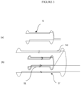
- the primary inductive antenna 5 is a volume antenna. For example, we could choose an antenna with Helmholtz geometry, a saddle geometry, or any other more complex volume geometry, in particular gradiometric.
- the first geometry (a) is of the saddle type, well known to those skilled in the art for its performance, particularly in terms of spatial homogeneity.
- the diameter of the saddle antenna horse is equal to 1.5 times its length.
- the 5' saddle gradiometric antenna allows to reject noise from sources located at a large distance in front of the dimensions of the 5' antenna, while benefiting from the homogeneity properties of the saddle geometry.
- a detailed description of the principle of gradiometric antennas can be found in the article by RL Fagaly, “Superconducting quantum interference device instruments and applications”, Review of scientific instruments 77, 101101 (2006 ).
- i 1 (resp. i 2 ) the current flowing in the antenna 5 (resp. the coil L 2 ) and ⁇ a the flux captured by the antenna 5.
- M k LiLs the input coil-SQUID mutual inductance
- M 12 k ′ L 1 L 2 the mutual between coils L 1 and L 2 .
- L s is the self-inductance of the SQUID 3 device.
- Ra 1 ⁇ .
- L a 0.1 mH. This value of L a sets a value for the capacitance:
- the ratio of inductances L 1 and L 2 is therefore imposed: or L 1 1390 L 2 .
- the precise values of L 1 and L 2 are fixed by the coupling constant k ! , which we seek to have as close as possible to 1 in order to ensure the maximum sensitivity of the device.
- the capacity found is extremely high, at these values we will have to use chemical capacities that may not be suitable for the cold of the cryostat.
- One solution is to increase the resistance of the primary antenna 5, which requires going through a flux transformer 2 to adapt the inductance in order to maintain the same bandwidth.
- the SQUID 3 device used is a low-Tc SQUID (e.g. SQ680 from STARCryo ® ) cooled by cryocooler (for “cryorefrigerator”, for example the PT 403 from CryoMech ® , and polarized by an i p current.
- cryocooler for “cryorefrigerator”, for example the PT 403 from CryoMech ® , and polarized by an i p current.
- the low-Tc SQUID has a much lower thermal noise level, which allows to drastically increase the signal-to-noise ratio and ultimately the quality of the final image. Its role is to read the current generated in the input coil, with a noise level of 0.8 pA / ⁇ Hz . This noise level is therefore the objective to be achieved for thermal noise in the inductive antenna.
- FLL flux-locked loop
- This loop first presents a pre-amplifier 40 (LNA) of the voltage measured at the terminals of the SQUID.
- LNA pre-amplifier 40
- amplification system There are two possible choices for the amplification system: either opt for SQUID amplification as is the case, for example, in the document US2013271142A , or use ASIC-type semiconductor heterostructure amplification, which is potentially more interesting but also poses more constraints, particularly in the maximum level of amplitude excursion in voltage of the incoming signal.
- the feedback coil 10 of inductance L feed allows to react to the variations of incoming flux to maintain the SQUID 3 at its maximum flux sensitivity level.
- the signal is read at the output of the flux-locked loop.
- the reduction of the working magnetic field by several orders of magnitude makes it possible to overcome the constraints preventing on the one hand a massive adoption of MRI as an imaging standard and on the other hand the opening of applications that do not yet exist such as MRI on board a truck to diagnose the type of stroke (vascular-cerebral accident): ischemic or hemorrhagic, the screening of cancer of the 100% MRI breast (performed by scanner today), or intra-operative MRI, thanks to lightweight equipment, without magnetic shielding, and inexpensive.
- FIG. 2 presents a schematic diagram of an MRI experiment carried out with the detection system according to the invention.
- the patient's knee is inserted into a cylinder A which includes a solenoid ensuring a permanent field B 0 ⁇ 1 mT homogeneous at approximately 10 ppm over a volume of approximately 10x10x10 cm 3 , gradients, and the receiving antenna described above.
- the receiving antenna is cooled to a temperature of approximately 60 K using a custom-made cryogenics system derived from the pulse tube ensuring the cooling of the SQUID system of part B.
- Part B includes the SQUID for reading the current from the inductive antenna, as well as the signal processing electronics described above, the pre-amplification system, and the flux-locked loop FLL composed of an integrating amplifier, a readout resistor, and a looping coil L feed .
- This entire stage is cooled using a cryogenic machine, for example the PT403 pulse tube from CryoMech, to a temperature of around 4.2 K.
- Part C provides analog-to-digital conversion of the signal for computer post-processing to drive the equipment and display the resulting MRI image.
- the sensitivity and portability of the device make it interesting primarily for magnetic resonance imaging (MRI).
- MRI magnetic resonance imaging
- the high levels of contrast obtained at low field make the technology interesting for diagnostics where contrast is currently insufficient, with high-field technologies.
- equipment according to the invention could easily be installed in an ambulance truck in order to quickly diagnose, at the scene of the accident, an ischemic or hemorrhagic stroke, in order to treat the patient more quickly and avoid irreparable damage to cognitive faculties.
- the imaging equipment according to the invention could also be widely used in cases where it is currently underused: screening for breast cancer in women over 50, use in neurology and psychiatry: early screening for diseases such as schizophrenia, depression, or epilepsy; screening for prostate cancer.
- NMR devices used in particular for chemical characterization can also benefit from our detection system to design lighter and less expensive equipment, for reasons similar to those put forward in the context of MRI.
- SQUID-based magnetic sensors for metal prospecting already exist in the mining industry, as illustrated in the document US 7,394,250 .
- Our detection system can also be integrated into such a device for mining prospecting, thanks to its very low noise level.
- the principle is as follows: an RF wave is emitted into the ground, if a metal vein is present, eddy currents are induced in the vein which in turn emits an RF wave, this wave is detected by our device integrating the SQUID detection system.
- Ultrasensitive radiofrequency sensors are well-known elements of electronic warfare systems: they are used, for example, to detect communication signals.
- Another interesting application is the detection of submerged submersibles: since the submersible is made of ferromagnetic materials, our device is able to detect its presence by emitting RF waves and detecting the waves produced by the induced eddy currents, on the same principle as mining prospecting.
- Other systems detect the disturbance of the local terrestrial field caused by the passage of the submarine, as illustrated in the document " Magnetic detection of a surface ship by an airborne LTS SQUID MAD” by Megumi Hirota et al., April 2001, IEEE Transactions on Applied Superconductivity 11(1):884 - 887 .
Landscapes
- Physics & Mathematics (AREA)
- General Physics & Mathematics (AREA)
- Life Sciences & Earth Sciences (AREA)
- Condensed Matter Physics & Semiconductors (AREA)
- Health & Medical Sciences (AREA)
- Engineering & Computer Science (AREA)
- Public Health (AREA)
- Animal Behavior & Ethology (AREA)
- Veterinary Medicine (AREA)
- General Health & Medical Sciences (AREA)
- Surgery (AREA)
- Remote Sensing (AREA)
- Biophysics (AREA)
- Pathology (AREA)
- Biomedical Technology (AREA)
- Heart & Thoracic Surgery (AREA)
- Medical Informatics (AREA)
- Molecular Biology (AREA)
- Radiology & Medical Imaging (AREA)
- Environmental & Geological Engineering (AREA)
- General Life Sciences & Earth Sciences (AREA)
- Electromagnetism (AREA)
- Geology (AREA)
- Nuclear Medicine, Radiotherapy & Molecular Imaging (AREA)
- Geophysics (AREA)
- Spectroscopy & Molecular Physics (AREA)
- High Energy & Nuclear Physics (AREA)
- Magnetic Resonance Imaging Apparatus (AREA)
- Measuring Magnetic Variables (AREA)
- Geophysics And Detection Of Objects (AREA)
- Measurement And Recording Of Electrical Phenomena And Electrical Characteristics Of The Living Body (AREA)
Claims (14)
- SQUID-basiertes Hochfrequenz-Erkennungs- und Erfassungssystem (HF-Erkennungs- und Erfassungssystem) (1), das insbesondere zum Integriertwerden in eine Kernspinresonanzeinrichtung (S), zum Beispiel eine Magnetresonanztomographieeinrichtung (MRT), vorgesehen ist, umfassend:- eine primäre Erkennungsantenne (5) von dem Volumentyp,- einen Flusstransformator (2),- eine SQUID-Vorrichtung (3), die zum Aufnehmen des magnetischen Flusses, der durch die primäre Antenne (5) aufgenommen und durch eine Eingangswicklung (8) innerhalb der SQUID-Vorrichtung über den Flusstransformator (2) reproduziert wird, und zum Liefern eines sekundären Erkennungssignals angeordnet ist,- eine Kryogenikvorrichtung, die zum Kühlen der SQUID-Vorrichtung (3) vorgesehen ist,- eine Stufe (4) zum Verarbeiten des sekundären Erkennungssignals, das durch die SQUID-Vorrichtung (3) ausgegeben wird, zum Liefern eines analogen Erfassungssignals, umfassend eine Flussregelschleife (FLL), die zum Linearisieren der Reaktion der SQUID-Vorrichtung (3) vorgesehen ist.
dadurch gekennzeichnet, dass die SQUID-Vorrichtung von dem Typ mit niedriger kritischer Temperatur ist, der Flusstransformator (2) eine primäre Wicklung (6) besitzt, die mit der primären Erkennungsantenne (5) verbunden ist, die Kryogenikvorrichtung ferner zum Kühlen des Flusstransformators vorgesehen ist, und dass die primäre Erkennungsantenne (5) Helmholtz- oder Sattelspulen umfasst. - Erkennungs- und Erfassungssystem nach Anspruch 1,
dadurch gekennzeichnet, dass die primäre Erkennungsantenne eine gradiometrische Geometrie aufweist. - Erkennungs- und Erfassungssystem (1) nach Anspruch 1,
dadurch gekennzeichnet, dass die Flussregelschleife (FLL) einen rauscharmen Verstärker (LNA) umfasst. - Erkennungs- und Erfassungssystem (1) nach Anspruch 3,
dadurch gekennzeichnet, dass der rauscharme Verstärker einen Halbleiterheterostrukturverstärker umfasst. - Erkennungs- und Erfassungssystem nach einem der Ansprüche 3 oder 4,
dadurch gekennzeichnet, dass der rauscharme Verstärker ein SQUID-basiertes Verstärkungssystem umfasst. - Erkennungs- und Erfassungssystem nach einem der vorstehenden Ansprüche, dadurch gekennzeichnet, dass es ferner eine oder mehrere Spulen für eine aktive Kompensation des Rauschens außerhalb des Systems umfasst.
- Erkennungs- und Erfassungssystem (1) nach einem der vorstehenden Ansprüche, dadurch gekennzeichnet, dass die primäre Erkennungsantenne (5) zum Konzentrieren des Flusses, der durch die SQUID-Vorrichtung aufgenommen wird, mit dem Flusstransformator (2) zusammenwirkt.
- Erkennungs- und Erfassungssystem (1) nach einem der vorstehenden Ansprüche, dadurch gekennzeichnet, dass es ferner innerhalb des Flusstransformators (2) eine induktive Rückkopplungsspule (10) umfasst, die zum Reagieren auf Schwankungen des eingehenden Flusses angeordnet ist, um die SQUID-Vorrichtung (3) bei maximalem Fluss auf seinem Empfindlichkeitsniveau zu halten.
- Ausrüstung (S) für eine Magnetresonanztomographie (MRT), umfassend:- ein SQUID-basiertes Hochfrequenz-Erkennungs- und Erfassungssystem (HF-Erkennungs- und Erfassungssystem) (B) nach einem der vorstehenden Ansprüche,- eine antennentragende Vorrichtung (A), die die primäre Erkennungsantenne von dem Volumentyp integriert und mit dem Erkennungs- und Erfassungssystem (B) verbunden ist,- eine Analog-Digital-Umwandlungsstufe (C), die zum Umwandeln des analogen Erfassungssignals in digitale Daten vorgesehen ist, die für eine Nachbearbeitung angepasst sind, um ein MRT-Bild zu erzeugen und anzuzeigen.
- MRT-Ausrüstung nach dem vorstehenden Anspruch,
dadurch gekennzeichnet, dass sie mit einer Magnetenzephalographievorrichtung (MEG) gekoppelt ist. - Kernspinresonanzausrüstung (NMR), einschließlich eines SQUID-basierten HF-Erkennungs- und Erfassungssystems nach einem der Ansprüche 1 bis 8.
- Magnetsensorausrüstung auf SQUID-Basis für die Metallsuche, einschließlich eines HF-Erkennungs- und Erfassungssystems nach einem der Ansprüche 1 bis 8, zum Erkennen einer Hochfrequenzwelle (HF-Welle), die durch eine Metallader als Reaktion auf eine Emission einer Hochfrequenzwelle (HF-Welle) in einen Boden emittiert wird.
- Hochempfindliche Hochfrequenzsensorausrüstung, einschließlich eines Erkennungs- und Erfassungssystems nach einem der Ansprüche 1 bis 8.
- Funkastronomieausrüstung, die in dem Bereich der Hochfrequenzen (HF) arbeitet, einschließlich eines SQUID-basierten HF-Erkennungs- und Erfassungssystems nach einem der Ansprüche 1 bis 8.
Applications Claiming Priority (2)
| Application Number | Priority Date | Filing Date | Title |
|---|---|---|---|
| FR2012642A FR3117218B1 (fr) | 2020-12-03 | 2020-12-03 | Système de détection et d'acquisition RF bas-bruit à base de SQUID et équipements intégrant ce système |
| PCT/FR2021/052187 WO2022117969A1 (fr) | 2020-12-03 | 2021-12-02 | Systeme de detection et d'acquisition rf bas-bruit a base de squid et equipements integrant ce systeme |
Publications (3)
| Publication Number | Publication Date |
|---|---|
| EP4256358A1 EP4256358A1 (de) | 2023-10-11 |
| EP4256358B1 true EP4256358B1 (de) | 2025-02-05 |
| EP4256358C0 EP4256358C0 (de) | 2025-02-05 |
Family
ID=74871518
Family Applications (1)
| Application Number | Title | Priority Date | Filing Date |
|---|---|---|---|
| EP21848262.8A Active EP4256358B1 (de) | 2020-12-03 | 2021-12-02 | Rauscharmes squid-basiertes rf-detektions- und erfassungssystem und ausrüstung mit diesem system |
Country Status (9)
| Country | Link |
|---|---|
| US (1) | US12461175B2 (de) |
| EP (1) | EP4256358B1 (de) |
| JP (1) | JP7728602B2 (de) |
| KR (1) | KR102938767B1 (de) |
| CN (1) | CN116547549B (de) |
| CA (1) | CA3200558A1 (de) |
| ES (1) | ES3021462T3 (de) |
| FR (1) | FR3117218B1 (de) |
| WO (1) | WO2022117969A1 (de) |
Families Citing this family (2)
| Publication number | Priority date | Publication date | Assignee | Title |
|---|---|---|---|---|
| FR3141770B1 (fr) | 2022-11-04 | 2025-01-17 | Chipiron | Appareil et procédé pour imager des corps métalliques ou partiellement métalliques par résonance magnétique, application de ce procédé à l’imagerie de cellules électrochimiques |
| FR3156896B1 (fr) | 2023-12-19 | 2025-12-12 | Thales Sa | Gradiomètre radiofréquence à SQUID |
Family Cites Families (16)
| Publication number | Priority date | Publication date | Assignee | Title |
|---|---|---|---|---|
| CN1287160A (zh) | 2000-07-03 | 2001-03-14 | 李家明 | 一种白酒的勾调方法 |
| WO2003067267A2 (en) | 2002-02-06 | 2003-08-14 | The Regents Of The University Of California | Squid detected nmr and mri at ultralow fields |
| JP2004177130A (ja) | 2002-11-22 | 2004-06-24 | National Institute For Materials Science | Nqr−squidによる地雷探知装置 |
| US7187169B2 (en) * | 2004-11-03 | 2007-03-06 | The Regents Of The University Of California | NMR and MRI apparatus and method |
| WO2006052236A1 (en) | 2004-11-03 | 2006-05-18 | The Regents Of The University Of California | Nmr and mri apparatus and method involving a squid magnetometer |
| JP2007029401A (ja) | 2005-07-26 | 2007-02-08 | Hitachi Ltd | 運動機能測定装置 |
| WO2008091712A2 (en) | 2007-01-25 | 2008-07-31 | California Institute Of Technology | Low field electron paramagnetic resonance imaging with squid detection |
| WO2008137485A2 (en) | 2007-05-04 | 2008-11-13 | California Institute Of Technology | Low field squid mri devices, components and methods |
| TWI395966B (zh) * | 2009-01-17 | 2013-05-11 | Univ Nat Taiwan | 時域核磁共振造影的方法及其裝置 |
| US8222899B2 (en) | 2009-04-21 | 2012-07-17 | Herng-Er Horng | Squid detected nuclear magnetic resonance and imaging at ultra-weak fields |
| KR101092490B1 (ko) | 2009-11-26 | 2011-12-13 | 한국표준과학연구원 | 자속고정회로, 자속고정방법, 및 squid 측정 장치 |
| JP2013181848A (ja) | 2012-03-02 | 2013-09-12 | Hitachi Ltd | 磁気計測装置及び磁気信号検出方法 |
| CN102830381B (zh) * | 2012-08-15 | 2014-11-12 | 中国科学院武汉物理与数学研究所 | 一种基于激光原子磁力计的nmr装置及测量方法 |
| CN105137374B (zh) | 2014-06-03 | 2018-09-25 | 中国科学院上海微系统与信息技术研究所 | 一种超高分辨率的磁共振成像方法及装置 |
| CN105738838B (zh) * | 2016-04-14 | 2018-12-14 | 中国科学院上海微系统与信息技术研究所 | 一种超导量子干涉器磁梯度计及高度平衡的磁场探测方法 |
| CN209673975U (zh) * | 2019-01-29 | 2019-11-22 | 上海联影医疗科技有限公司 | 磁共振线圈组件及磁共振系统 |
-
2020
- 2020-12-03 FR FR2012642A patent/FR3117218B1/fr active Active
-
2021
- 2021-12-02 CN CN202180081713.3A patent/CN116547549B/zh active Active
- 2021-12-02 JP JP2023557831A patent/JP7728602B2/ja active Active
- 2021-12-02 KR KR1020237022105A patent/KR102938767B1/ko active Active
- 2021-12-02 EP EP21848262.8A patent/EP4256358B1/de active Active
- 2021-12-02 CA CA3200558A patent/CA3200558A1/fr active Pending
- 2021-12-02 WO PCT/FR2021/052187 patent/WO2022117969A1/fr not_active Ceased
- 2021-12-02 ES ES21848262T patent/ES3021462T3/es active Active
- 2021-12-02 US US18/255,967 patent/US12461175B2/en active Active
Also Published As
| Publication number | Publication date |
|---|---|
| US20240045005A1 (en) | 2024-02-08 |
| US12461175B2 (en) | 2025-11-04 |
| WO2022117969A1 (fr) | 2022-06-09 |
| CA3200558A1 (fr) | 2022-06-09 |
| ES3021462T3 (en) | 2025-05-27 |
| KR102938767B1 (ko) | 2026-03-13 |
| JP2023553572A (ja) | 2023-12-22 |
| CN116547549A (zh) | 2023-08-04 |
| EP4256358A1 (de) | 2023-10-11 |
| JP7728602B2 (ja) | 2025-08-25 |
| FR3117218B1 (fr) | 2023-03-17 |
| FR3117218A1 (fr) | 2022-06-10 |
| CN116547549B (zh) | 2025-12-23 |
| KR20230110804A (ko) | 2023-07-25 |
| EP4256358C0 (de) | 2025-02-05 |
Similar Documents
| Publication | Publication Date | Title |
|---|---|---|
| US6054856A (en) | Magnetic resonance detection coil that is immune to environmental noise | |
| US20140103927A1 (en) | Low-field magnetic resonance system (lf-mrs) for producing an mri image | |
| EP2035852B1 (de) | Vorrichtung und verfahren zur messung eines magnetresonanzsignals mittels eines einen supraleiter und ein magnetoresistives element enthaltenden hybridsensors | |
| Silani et al. | Nuclear quadrupole resonance spectroscopy with a femtotesla diamond magnetometer | |
| EP4256358B1 (de) | Rauscharmes squid-basiertes rf-detektions- und erfassungssystem und ausrüstung mit diesem system | |
| Augustine et al. | Low field magnetic resonance images of polarized noble gases obtained with a dc superconducting quantum interference device | |
| Lin et al. | High-sensitivity cooled coil system for nuclear magnetic resonance in kHz range | |
| KR20180040572A (ko) | 자기공명 영상장치 | |
| Ran et al. | A highly integrated, high-sensitivity magnetometer based on diamond nitrogen-vacancy centers | |
| Monea et al. | An optimized NQR spectrometer for detection of prohibited substances | |
| Hu et al. | Design of high sensitivity magnetometer based on Diamond Nitrogen-Vacancy Centers and Weak Signal Output Module | |
| Martin et al. | Rapid Measurement of Magnetic Particle Concentrations in Wildland–Urban Interface Fire Ashes and Runoff Using Compact NMR | |
| Körber et al. | Nuclear magnetic resonance on room temperature samples in nanotesla fields using a two-stage dc superconducting quantum interference device sensor | |
| CN119452264A (zh) | 用于采用永久磁体的移动mri的方法和设备 | |
| EP4508453B1 (de) | Radiometrischer volumenflusskonzentrator für ultraempfindliche magnetische detektion und squid-basiertes magnetisches detektionssystem mit diesem flusskonzentrator | |
| US12204000B2 (en) | Precision magnetometer | |
| Schlenga et al. | High-T/sub c/SQUIDs for low-field NMR and MRI of room temperature samples | |
| FR3156896A1 (fr) | Gradiomètre radiofréquence à SQUID | |
| FR3141770A1 (fr) | Appareil et procédé pour imager des corps métalliques ou partiellement métalliques par résonance magnétique, application de ce procédé à l’imagerie de cellules électrochimiques | |
| Ejalonibu et al. | Towards the design and operation of a uniformly illuminated NV detector for magnetic field mapping applications | |
| Czakon et al. | Microwave kinetic inductance detector (MKID) camera testing for submillimeter astronomy | |
| Hemnani | Development of Low Frequency Pulsed NQR/NMR Spectrometer | |
| JP2023034046A (ja) | 脳計測装置 | |
| FR3077392A1 (fr) | Systeme de bobines pour utilisation en resonance magnetique nucleaire et imagerie par resonance magnetique nucleaire | |
| FR2817047A1 (fr) | Procede de mesure par resonance magnetique nucleaire avec suppression des echos |
Legal Events
| Date | Code | Title | Description |
|---|---|---|---|
| STAA | Information on the status of an ep patent application or granted ep patent |
Free format text: STATUS: UNKNOWN |
|
| STAA | Information on the status of an ep patent application or granted ep patent |
Free format text: STATUS: THE INTERNATIONAL PUBLICATION HAS BEEN MADE |
|
| PUAI | Public reference made under article 153(3) epc to a published international application that has entered the european phase |
Free format text: ORIGINAL CODE: 0009012 |
|
| STAA | Information on the status of an ep patent application or granted ep patent |
Free format text: STATUS: REQUEST FOR EXAMINATION WAS MADE |
|
| 17P | Request for examination filed |
Effective date: 20230530 |
|
| AK | Designated contracting states |
Kind code of ref document: A1 Designated state(s): AL AT BE BG CH CY CZ DE DK EE ES FI FR GB GR HR HU IE IS IT LI LT LU LV MC MK MT NL NO PL PT RO RS SE SI SK SM TR |
|
| DAX | Request for extension of the european patent (deleted) | ||
| RAV | Requested validation state of the european patent: fee paid |
Extension state: MA Effective date: 20230530 |
|
| GRAP | Despatch of communication of intention to grant a patent |
Free format text: ORIGINAL CODE: EPIDOSNIGR1 |
|
| STAA | Information on the status of an ep patent application or granted ep patent |
Free format text: STATUS: GRANT OF PATENT IS INTENDED |
|
| INTG | Intention to grant announced |
Effective date: 20240711 |
|
| RIN1 | Information on inventor provided before grant (corrected) |
Inventor name: LABAT, DIMITRI |
|
| GRAS | Grant fee paid |
Free format text: ORIGINAL CODE: EPIDOSNIGR3 |
|
| GRAA | (expected) grant |
Free format text: ORIGINAL CODE: 0009210 |
|
| STAA | Information on the status of an ep patent application or granted ep patent |
Free format text: STATUS: THE PATENT HAS BEEN GRANTED |
|
| AK | Designated contracting states |
Kind code of ref document: B1 Designated state(s): AL AT BE BG CH CY CZ DE DK EE ES FI FR GB GR HR HU IE IS IT LI LT LU LV MC MK MT NL NO PL PT RO RS SE SI SK SM TR |
|
| REG | Reference to a national code |
Ref country code: GB Ref legal event code: FG4D Free format text: NOT ENGLISH |
|
| REG | Reference to a national code |
Ref country code: CH Ref legal event code: EP |
|
| REG | Reference to a national code |
Ref country code: DE Ref legal event code: R096 Ref document number: 602021025827 Country of ref document: DE |
|
| REG | Reference to a national code |
Ref country code: IE Ref legal event code: FG4D Free format text: LANGUAGE OF EP DOCUMENT: FRENCH |
|
| U01 | Request for unitary effect filed |
Effective date: 20250220 |
|
| U07 | Unitary effect registered |
Designated state(s): AT BE BG DE DK EE FI FR IT LT LU LV MT NL PT RO SE SI Effective date: 20250228 |
|
| REG | Reference to a national code |
Ref country code: ES Ref legal event code: FG2A Ref document number: 3021462 Country of ref document: ES Kind code of ref document: T3 Effective date: 20250527 |
|
| PG25 | Lapsed in a contracting state [announced via postgrant information from national office to epo] |
Ref country code: RS Free format text: LAPSE BECAUSE OF FAILURE TO SUBMIT A TRANSLATION OF THE DESCRIPTION OR TO PAY THE FEE WITHIN THE PRESCRIBED TIME-LIMIT Effective date: 20250505 |
|
| PG25 | Lapsed in a contracting state [announced via postgrant information from national office to epo] |
Ref country code: PL Free format text: LAPSE BECAUSE OF FAILURE TO SUBMIT A TRANSLATION OF THE DESCRIPTION OR TO PAY THE FEE WITHIN THE PRESCRIBED TIME-LIMIT Effective date: 20250205 |
|
| PG25 | Lapsed in a contracting state [announced via postgrant information from national office to epo] |
Ref country code: IS Free format text: LAPSE BECAUSE OF FAILURE TO SUBMIT A TRANSLATION OF THE DESCRIPTION OR TO PAY THE FEE WITHIN THE PRESCRIBED TIME-LIMIT Effective date: 20250605 |
|
| PG25 | Lapsed in a contracting state [announced via postgrant information from national office to epo] |
Ref country code: HR Free format text: LAPSE BECAUSE OF FAILURE TO SUBMIT A TRANSLATION OF THE DESCRIPTION OR TO PAY THE FEE WITHIN THE PRESCRIBED TIME-LIMIT Effective date: 20250205 |
|
| PG25 | Lapsed in a contracting state [announced via postgrant information from national office to epo] |
Ref country code: GR Free format text: LAPSE BECAUSE OF FAILURE TO SUBMIT A TRANSLATION OF THE DESCRIPTION OR TO PAY THE FEE WITHIN THE PRESCRIBED TIME-LIMIT Effective date: 20250506 |
|
| PG25 | Lapsed in a contracting state [announced via postgrant information from national office to epo] |
Ref country code: SM Free format text: LAPSE BECAUSE OF FAILURE TO SUBMIT A TRANSLATION OF THE DESCRIPTION OR TO PAY THE FEE WITHIN THE PRESCRIBED TIME-LIMIT Effective date: 20250205 |
|
| PG25 | Lapsed in a contracting state [announced via postgrant information from national office to epo] |
Ref country code: CZ Free format text: LAPSE BECAUSE OF FAILURE TO SUBMIT A TRANSLATION OF THE DESCRIPTION OR TO PAY THE FEE WITHIN THE PRESCRIBED TIME-LIMIT Effective date: 20250205 |
|
| PG25 | Lapsed in a contracting state [announced via postgrant information from national office to epo] |
Ref country code: SK Free format text: LAPSE BECAUSE OF FAILURE TO SUBMIT A TRANSLATION OF THE DESCRIPTION OR TO PAY THE FEE WITHIN THE PRESCRIBED TIME-LIMIT Effective date: 20250205 |
|
| PLBE | No opposition filed within time limit |
Free format text: ORIGINAL CODE: 0009261 |
|
| STAA | Information on the status of an ep patent application or granted ep patent |
Free format text: STATUS: NO OPPOSITION FILED WITHIN TIME LIMIT |
|
| REG | Reference to a national code |
Ref country code: CH Ref legal event code: L10 Free format text: ST27 STATUS EVENT CODE: U-0-0-L10-L00 (AS PROVIDED BY THE NATIONAL OFFICE) Effective date: 20251217 |
|
| REG | Reference to a national code |
Ref country code: CH Ref legal event code: U11 Free format text: ST27 STATUS EVENT CODE: U-0-0-U10-U11 (AS PROVIDED BY THE NATIONAL OFFICE) Effective date: 20260101 |
|
| PGFP | Annual fee paid to national office [announced via postgrant information from national office to epo] |
Ref country code: GB Payment date: 20251219 Year of fee payment: 5 |
|
| 26N | No opposition filed |
Effective date: 20251106 |
|
| PGFP | Annual fee paid to national office [announced via postgrant information from national office to epo] |
Ref country code: TR Payment date: 20251206 Year of fee payment: 5 |
|
| PGFP | Annual fee paid to national office [announced via postgrant information from national office to epo] |
Ref country code: IE Payment date: 20251219 Year of fee payment: 5 |
|
| U20 | Renewal fee for the european patent with unitary effect paid |
Year of fee payment: 5 Effective date: 20251230 |
|
| VS25 | Lapsed in a validation state [announced via postgrant information from nat. office to epo] |
Ref country code: MA Free format text: FAILURE TO ELECT DOMICILE IN THE NATIONAL COUNTRY Effective date: 20250506 |
|
| VS25 | Lapsed in a validation state [announced via postgrant information from nat. office to epo] |
Ref country code: MA Free format text: LAPSE BECAUSE OF FAILURE TO SUBMIT A TRANSLATION OF THE DESCRIPTION OR TO PAY THE FEE WITHIN THE PRESCRIBED TIME-LIMIT Effective date: 20250205 |
|
| PGFP | Annual fee paid to national office [announced via postgrant information from national office to epo] |
Ref country code: ES Payment date: 20260130 Year of fee payment: 5 |
|
| PGFP | Annual fee paid to national office [announced via postgrant information from national office to epo] |
Ref country code: NO Payment date: 20251230 Year of fee payment: 5 |
|
| PGFP | Annual fee paid to national office [announced via postgrant information from national office to epo] |
Ref country code: CH Payment date: 20260101 Year of fee payment: 5 |