EP4255698B1 - Kopplungsvorrichtung, system mit einem autonomen fahrzeug und einer patiententransportvorrichtung, sowie verfahren zum betreiben eines solchen systems - Google Patents
Kopplungsvorrichtung, system mit einem autonomen fahrzeug und einer patiententransportvorrichtung, sowie verfahren zum betreiben eines solchen systems Download PDFInfo
- Publication number
- EP4255698B1 EP4255698B1 EP21835164.1A EP21835164A EP4255698B1 EP 4255698 B1 EP4255698 B1 EP 4255698B1 EP 21835164 A EP21835164 A EP 21835164A EP 4255698 B1 EP4255698 B1 EP 4255698B1
- Authority
- EP
- European Patent Office
- Prior art keywords
- autonomous vehicle
- coupling
- coupling device
- patient transport
- transport device
- Prior art date
- Legal status (The legal status is an assumption and is not a legal conclusion. Google has not performed a legal analysis and makes no representation as to the accuracy of the status listed.)
- Active
Links
Images


Classifications
-
- B—PERFORMING OPERATIONS; TRANSPORTING
- B25—HAND TOOLS; PORTABLE POWER-DRIVEN TOOLS; MANIPULATORS
- B25J—MANIPULATORS; CHAMBERS PROVIDED WITH MANIPULATION DEVICES
- B25J11/00—Manipulators not otherwise provided for
- B25J11/008—Manipulators for service tasks
- B25J11/009—Nursing, e.g. carrying sick persons, pushing wheelchairs, distributing drugs
-
- A—HUMAN NECESSITIES
- A61—MEDICAL OR VETERINARY SCIENCE; HYGIENE
- A61G—TRANSPORT, PERSONAL CONVEYANCES, OR ACCOMMODATION SPECIALLY ADAPTED FOR PATIENTS OR DISABLED PERSONS; OPERATING TABLES OR CHAIRS; CHAIRS FOR DENTISTRY; FUNERAL DEVICES
- A61G5/00—Chairs or personal conveyances specially adapted for patients or disabled persons, e.g. wheelchairs
- A61G5/04—Chairs or personal conveyances specially adapted for patients or disabled persons, e.g. wheelchairs motor-driven
- A61G5/047—Chairs or personal conveyances specially adapted for patients or disabled persons, e.g. wheelchairs motor-driven by a modular detachable drive system
-
- A—HUMAN NECESSITIES
- A61—MEDICAL OR VETERINARY SCIENCE; HYGIENE
- A61G—TRANSPORT, PERSONAL CONVEYANCES, OR ACCOMMODATION SPECIALLY ADAPTED FOR PATIENTS OR DISABLED PERSONS; OPERATING TABLES OR CHAIRS; CHAIRS FOR DENTISTRY; FUNERAL DEVICES
- A61G7/00—Beds specially adapted for nursing; Devices for lifting patients or disabled persons
- A61G7/08—Apparatus for transporting beds
-
- B—PERFORMING OPERATIONS; TRANSPORTING
- B25—HAND TOOLS; PORTABLE POWER-DRIVEN TOOLS; MANIPULATORS
- B25J—MANIPULATORS; CHAMBERS PROVIDED WITH MANIPULATION DEVICES
- B25J19/00—Accessories fitted to manipulators, e.g. for monitoring, for viewing; Safety devices combined with or specially adapted for use in connection with manipulators
- B25J19/0004—Braking devices
-
- B—PERFORMING OPERATIONS; TRANSPORTING
- B25—HAND TOOLS; PORTABLE POWER-DRIVEN TOOLS; MANIPULATORS
- B25J—MANIPULATORS; CHAMBERS PROVIDED WITH MANIPULATION DEVICES
- B25J5/00—Manipulators mounted on wheels or on carriages
- B25J5/007—Manipulators mounted on wheels or on carriages mounted on wheels
Definitions
- the invention relates to a coupling device for coupling an autonomous vehicle to a patient transport device.
- the invention also relates to an associated system and a method for operating such a system.
- Using the coupling device not only can modules such as wheelchairs, walkers or patient beds be coupled, but the system also enables guided passenger transport, in which an independently walking person can hold on to the patient transport device.
- the WO 2016/192857 A2 describes a robot system for transporting a movable object, in particular a hospital bed, wherein the robot system comprises at least two robots and both robots can each be coupled to the movable object, in particular to a coupling device of the movable object, in such a way that a force from at least one of the robots can be transferred to the movable object, so that the robots can jointly transport the movable object.
- the US 2012029697 A1 discloses a robotic transport device with a transport body and two docking arms. Furthermore, a controller is provided, by means of which the transport device is autonomously movable and can approach a target device, determine its type and adjust the two docking arms according to the type of device. In addition, the transport device has wheel stoppers, which can also be adjusted according to the type of device. A corresponding The target device coupled to the transport device can then be moved autonomously.
- the EP 3283308 B1 shows a robotic trolley-pulling vehicle that can be docked onto a trolley, in particular a laundry trolley in a hospital, and can pull it.
- the vehicle has a gripper for holding the trolley.
- a positioning system is also provided and one or more sensors to avoid unnecessary collisions with the environment.
- the object of the invention is to create a coupling device with the aid of which a large number of different patient transport devices can be selectively coupled to the same autonomous vehicle in a simple manner.
- the object is also achieved by a corresponding system, comprising a patient transport device, an autonomous vehicle and a coupling device coupling the autonomous vehicle to the patient transport device, and a corresponding method for operating the system.
- the coupling device forms a largely universal connection means for selectively connecting a mobile vehicle to a large number of different patient transport devices, so that the mobile vehicle can automatically move or drive the currently coupled patient transport device from a first location to a second location.
- rollators which represent a walking aid in which the guided person walks independently but supports themselves on the rollator, are also understood as patient transport devices.
- the autonomous vehicle itself is also understood as a patient transport device if the coupling device is connected to a handle or the coupling device directly has or forms the handle, and a person walking independently holds on to the handle and is guided and/or supported by it.
- the handle can also be considered the patient transport device.
- patients are understood to be not only sick people who are in a hospital, but also other people who are, for example, in a rehabilitation clinic, in a nursing home, in a retirement home or at home and who need or want appropriate support.
- the autonomous vehicle can comprise a chassis, such as wheels rotatably mounted on the chassis, of which at least one wheel is automatically driven.
- the one wheel or the multiple wheels can be controlled by a driving control.
- the driving control which can be part of the autonomous vehicle, the autonomous vehicle is automatically moved and in particular automatically navigated from a first location to a second location.
- the driving control can be connected to a navigation control.
- the navigation control can be located in the autonomous vehicle or it can be a separate part of a navigation system that is separate from the autonomous vehicle. In the latter case, the driving control is connected to the navigation system in terms of control technology, in particular wirelessly.
- the patient transport device can be, for example, a hospital bed, a wheelchair or a walker.
- the patient transport device can also be merely a handle or a handrail to which a person can hold on in order to reduce the risk of falling, wherein the handle or handrail is automatically moved by the autonomous vehicle, i.e. is displaced, in order to automatically guide the person holding on to the handle or handrail from a first location to a second location.
- an autonomous vehicle which has the coupling device according to the invention can also be used to move or drive other transport devices.
- the coupling device can be brought into a storage position so that it remains unused, but the autonomous vehicle can, for example, pick up a transport shelf and move it while carrying it.
- the coupling device according to the invention can alternatively also be used to couple the autonomous vehicle to the transport shelf so that the autonomous vehicle can pull the transport shelf like a trailer.
- the transport shelf would have to have its own wheels for driving the transport shelf, which is regularly the case in the medical field, such as in hospitals.
- the connecting member which is designed to attach the coupling device to an autonomous vehicle, can be designed to permanently attach the coupling device to the autonomous vehicle.
- the autonomous vehicle then forms a driving unit together with the coupling device for attaching a patient transport device.
- the connecting member but can also be designed to be manually detachable so that the coupling device can be separated from or reattached to the autonomous vehicle if necessary.
- the first link enables the position of the swivel joint to be adjusted relative to the autonomous vehicle when the coupling device is arranged on the autonomous vehicle.
- This design also enables the autonomous vehicle to rotate around its own vertical axis under the coupling device without the link and the coupling rod rotating.
- the first link can be formed by a straight connecting rod.
- the first link can also have a different shape if necessary.
- the first link can have a curved shape or have one or more bend areas.
- the proximal end section and the distal end section define the two opposite end sections of the respective designed link, regardless of how the link or a central section of the link is designed.
- the handlebar With its proximal end section, the handlebar is rotatably mounted on the connecting link of the coupling device via the swivel joint.
- the proximal end section is defined as the end section of the handlebar which is closer to the connecting link in the kinematic chain of swivel joint and pivot joint or closer to the autonomous vehicle in the system and further away from the connecting section of the coupling rod or further away from the transport device in the system.
- the distal end section is defined as the end section of the handlebar which is closer to the connecting link in the kinematic chain of swivel joint and pivot joint or Swivel joint is further away from the connecting member or, in the system, further away from the autonomous vehicle and is closer to the connecting section of the coupling rod or, in the system, closer to the transport device.
- the angled coupling rod can be formed at an obtuse angle or an acute angle.
- the angled coupling rod can be formed at a right angle, so that the proximal leg and the distal leg abut one another at least approximately at a 90-degree angle, at least in their connecting areas.
- the proximal leg and the distal leg can each be formed by straight rod sections or tube sections.
- the proximal leg and/or the distal leg can each be formed by bent, curved or cranked rod sections or tube sections.
- the proximal leg is defined as the leg of the coupling rod which, in the kinematic chain of rotary joint and swivel joint, is closer to the connecting link or, in the system, is closer to the autonomous vehicle and is further away from the connecting section of the coupling rod or, in the system, is further away from the transport device.
- the distal leg is defined as the leg of the coupling rod which, in the kinematic chain of rotary joint and swivel joint, is further away from the connecting link or, in the system, is further away from the autonomous vehicle and is closer to the connecting section of the coupling rod or, in the system, is closer to the transport device.
- the swivel joint can have a maximum swivel angle that is less than 360 degrees, in particular less than than 180 degrees.
- the swivel joint can also be designed for rotations of more than 360 degrees or for free rotation.
- the swivel joint can also be designed as a rotary joint.
- the swivel joint can be designed for rotations of more than 360 degrees or for free rotation.
- the swivel joint can also alternatively be designed with a maximum angle of rotation that is less than 360 degrees, in particular less than 180 degrees.
- the swivel joint can also be designed as a pivot joint.
- connection section for coupling the coupling device to a patient transport device can already be formed by a simple rod section or tube section of the distal leg.
- the distal leg of the coupling rod can be hooked behind a structural element of the transport device, for example behind a chassis frame part of a hospital bed, a wheelchair or a walker.
- the connection section can have mechanical connecting means with which the coupling device can be attached to the respective transport device.
- the connecting means can be, for example, clamping jaws, gripper fingers, hooks or similar positive and/or non-positive connecting means.
- the swivel joint by means of which the proximal end section of the handlebar is rotatably mounted on the connecting member of the coupling device, can have a rotation axis which is vertically aligned in an arrangement of the coupling device coupled to the autonomous vehicle
- the swivel joint by means of which the proximal leg of the coupling rod is pivotally mounted on the distal end section of the handlebar, can have a swivel axis which is at least substantially horizontally aligned in an arrangement of the coupling device coupled to the autonomous vehicle.
- the entire coupling device By aligning the axis of rotation of the swivel joint vertically, the entire coupling device can be pivoted in different directions relative to the autonomous vehicle.
- the connection section of the coupling device By aligning the axis of rotation of the swivel joint horizontally, the connection section of the coupling device, in particular a handle section of the coupling device, can be adjusted, i.e. adapted, to its respective height.
- the swivel joint can thus have a swivel axis which, in an arrangement of the coupling device coupled to the autonomous vehicle, is vertically aligned in all driving positions of the autonomous vehicle on a horizontal driving plane, and the swivel joint can have a swivel axis which, in an arrangement of the coupling device coupled to the autonomous vehicle, is always horizontally aligned in all possible rotational positions of the swivel joint and in all driving positions of the autonomous vehicle on a horizontal driving plane.
- the swivel joint and/or the pivot joint can be lockable, freely rotatable in a non-locked manner, from a
- the rotary movement must be designed to be braked and/or automatically driven.
- the respective joint can have a locking device which is designed to lock the respective joint in a number of different joint angle positions, which in this respect form locking steps of the joint.
- the locking device can have, for example, two claw coupling-like locking bodies which have end faces facing each other and which have locking profiles that complement the shape.
- a first locking body and a second locking body of the locking device can be preloaded against each other with their end faces facing each other by means of a spring device.
- the joint can also be used as a safety coupling.
- the respective joint can have a brake.
- the respective brake can be operated manually or can be automatically activated and deactivated. In the case of an automatically activated and deactivated brake, this can be an electromechanical brake, for example.
- the respective joint can have a motor, in particular an electric motor.
- the electric motor and/or possibly other electrical components of the coupling device can be supplied with electrical energy via the autonomous vehicle.
- the electrical cables or electrical lines required for the supply of electrical energy can in particular be laid and/or guided inside the coupling device, for example in a hollow tube of the coupling device.
- the coupling device can have an electrical connector which interacts with an electrical mating connector of the autonomous vehicle, so that electrical energy can be transmitted from the autonomous vehicle to the coupling device when the coupling device is attached to the autonomous vehicle.
- the rotary joint and/or the swivel joint can be designed to be automatically lockable and/or manually lockable.
- the swivel joint can be designed to mount the proximal end portion of the handlebar on the connecting member of the coupling device so that it can rotate over at least 360 degrees.
- the swivel joint can be designed to pivotally mount the proximal leg of the coupling rod on the distal end section of the handlebar in a predetermined number of different swivel positions.
- the proximal leg of the coupling rod can also be continuously adjustable by means of the swivel joint, i.e. continuously adjustable and thus lockable in any position.
- the coupling rod can be in a parking position or in a niche of the autonomous vehicle, in particular at least partially or completely hidden, in a storage position.
- the distal leg of the angled coupling rod can be configured to form both a connection portion and a handle portion.
- this can have connecting means, for example clamping jaws, gripper fingers, hooks or similar positive and/or non-positive connecting means, in order to be able to connect the coupling device to the respective patient transport device.
- connecting means for example clamping jaws, gripper fingers, hooks or similar positive and/or non-positive connecting means, in order to be able to connect the coupling device to the respective patient transport device.
- the swivel joint can have a first overload protection device which is designed to switch the locked, braked or driven swivel joint to a torque-free state when the transmitted torque exceeds a predetermined maximum torque and/or the swivel joint can have a second overload protection device which is designed to switch the locked, braked or driven swivel joint to a torque-free state when the transmitted torque exceeds a predetermined maximum torque.
- a system for automatically moving a patient transport device by means of an autonomous vehicle comprising a patient transport device, an autonomous vehicle and a coupling device coupling the autonomous vehicle to the patient transport device, according to one embodiment or according to several embodiments, as described.
- the invention represents a concept for a multi-mobility extension of patients in hospitals or in care facilities by automating patient transport, with the aim of relieving the burden on nursing staff so that they have more time available for the actual nursing activities.
- One advantage of this can be that the necessary scenarios for transporting people can be implemented without modifying the patient transport devices to be transported, including guided transport of people, regardless of the type of walker or wheelchair, for example.
- the technical solution described below is based on simple kinematics, the coupling device, which, in combination with sensible use of the flexibility of the mobile platform, can couple with the systems in a clever way and offers a high level of mobility for the overall system. This can be essential because the space available in care facilities or hospitals is limited and properties such as the smallest possible turning circle therefore play an important role.
- the invention presented automates the transport of people in the scenarios of guided passenger transport, the patient walking with a walker, the patient sitting in a wheelchair and the patient transporting the patient lying in bed.
- the main component of the invention is a coupling system that can be used for patient transport in various modes and offers a multi-mobility module for people.
- the overall system has a high degree of flexibility despite the simple kinematics of the actual coupling module.
- a further advantage is that the system can be coupled with the various modules and thus flexibly combined. so that only a minimal number of these devices are needed to enable the mobility and flexibility of a variety of modules with the patient.
- the main components and their characteristics are discussed below.
- the focus of the invention is on the coupling device, i.e. the coupling module, which is why its components are explained in more detail.
- any mobile platform with a differential drive can be used as the mobile platform, the specifications of which meet the requirements of the application.
- the mobile platform can be equipped with laser scanners and cameras for safety and navigation, for example, and optionally have a lifting mechanism, the movement of which can be used, for example, to lift objects or modules or as a drive element for a coupling mechanism between the coupling module and the object to be transported.
- the mobile platform has the appropriate specifications for the loads to be handled and has, for example, two laser scanners and a lifting mechanism.
- the advantage of the concepts proposed here is that the modular design means that any platform that meets the requirements can be used.
- the coupling module consists of three main components, each of which implements one or more functions and, when combined, provides a simple coupling module with a variety of functions and great flexibility, which is essential for the multi-mobility module and enables the various transport modes in a meaningful way.
- the coupling module itself is simply constructed and uses the Degrees of freedom of the mobile platform to realize functions, which makes the system have a simple structure but can realize various functions.
- a drawbar suspension can complement the first joint of the kinematic chain of the coupling module and is characterized in that the axis of rotation intersects the axes of the drive wheels of the mobile platform at a 90° angle.
- the known driving systems usually have a large turning circle.
- the arrangement of the axes presented here solves this technical problem in a sensible way by reducing the turning circle to the minimum possible dimensions in which the module to be pulled can be turned on the spot when turning.
- a minimum radius results in the collision radius of the module to be pulled when turning on the spot, added to the length of the coupling module and the collision radius when turning on the spot of the mobile platform.
- a 180° turn of the entire system in a very small space is carried out in three individual movements one after the other.
- the mobile platform turns 90° on the spot, which is made possible by the differential drive in combination with the swivel joint of the coupling module.
- the mobile platform is then driven so that it moves around the module to be pulled. This is done in such a way that the pivot point of the module to be transported is exactly in the middle of its own two main wheels on the wheel axle.
- the mobile platform turns 90° again on the spot so that the main direction of travel is now rotated 180° compared to the platform orientation before the turning maneuver and the entire system can continue driving.
- a brake or a lock can be integrated into the joint so that the relative movement between the mobile platform and the coupling module can be blocked. This is useful for one variant of coupling and is described in more detail below.
- the locking of the joint can be automatic or manual. To use the locking mechanism to implement the coupling option, it must only be possible to lock the joint in its zero position. In addition to a holding or parking brake, this can also be achieved more easily, for example with simple locking mechanisms or locking partners, since no large loads need to be transferred in this state. This can be done using a force-locking and/or form-locking connection.
- Possibilities for this include a pin connection, where one joint partner has a pin or a pin-like element, preferably tapered, to compensate for small deviations in the joint alignment and prevent the connection from jamming.
- the other joint partner has the corresponding counterpart, for example a blind hole or a tapered hole.
- a pin and hole other geometries are also conceivable and useful, such as a toothing, a pairing of cone and ball or a wedge connection.
- the connection can be released and locked again either manually by hand or automatically.
- the lifting mechanism in the platform can be used for automatic release. used.
- only one of the connection partners can be attached to the vehicle frame and the other partner to the lifting frame. The lifting movement joins the elements together and locks them.
- the joint itself is passive, but can use the function of the lift to lock the joint autonomously.
- Other options for automatic operation include actuator elements, small linear drives or lifting magnets.
- the use of shaped elements can also be used for a safety function. For example, if a coupling process is to take place and an unexpected interference contour prevents the coupling process, the locking of the joint partners is automatically released in the event of an overload. This limit can be set by the shape of the joint partners and the normal force that is applied for coupling. If the locking is done manually, the preload force can be set using a spring element and the force to be applied to release the decoupling can be specifically set by selecting the spring elements.
- the second joint in the kinematic chain is the swivel joint. It can have three or any number of selectable main positions. These preferably three or four positions enable the various scenarios (personnel and module transport) to be implemented in a sensible manner. Intermediate positions are not necessary, which is why the joint can be designed as a tristable joint. This enables simple actuation and control of the joint.
- the three positions of the joint can be realized force-locking and/or form-locking and the changeover from one mode to another can be done manually or automatically.
- Manual adjustment can be carried out, for example, by loosening a positive connection and/or a pre-tension. After the link of the coupling module has been moved into the desired position, the connection can be restored and the system is ready for use in the desired scenario.
- the pre-tension can be achieved, for example, using a spring element.
- the combination of a pre-tension and suitable form elements of the joint partners ensures that one of the preferably three joint positions is always adopted, even if the position is not exactly right. This means that small deviations can be compensated for and the adjustment can be carried out quickly and manually.
- Another option is a joint with an integrated thread into which a screw can be mounted. If the screw is loosened, one link can be moved into the desired position relative to the other link. By tightening the screw connection, the parts are pressed together again and a force-locking connection is created.
- a wire made of a shape memory alloy can be used as an actuator.
- a spring preload one link can be held in the middle position. If the mode is to be changed, one of two shape memory elements acting against each other is energized, depending on the direction in which the link is to be moved, whereby it contracts due to the material due to the Joule heat and the structural part accordingly against the spring preload from the center position or from the neutral position.
- form element partners can be provided that ensure that the joint locks into place at the desired location.
- the structural part of the coupling area of the coupling module contains the functional surfaces for coupling with the modules to be pulled, as well as the haptic interface for the patients during guided patient transport.
- the coupling area is characterized by the fact that it can couple with the various models of modules such as wheelchairs or walkers without conversion.
- One possible form is a straight rod, optionally with a push element, which can be pushed automatically or manually to the coupling point of the module to be coupled.
- the actual connection to the support structure of the module to be coupled can be force-fitting and/or form-fitting. This can be done via a screw connection, clamp connection or lock.
- a clever form of the coupling area has coupling elements or a simple mechanism that can connect to the support structure of the modules to be transported.
- These coupling elements can be opened and closed. These movements can be triggered by the lifting of the mobile platform, for example by attaching a rope or wire to the vehicle frame and from there leading it along the lifting frame and the coupling module to the coupling form elements.
- the coupling form elements can be articulated and connected to the rope or the wire element. If the lifting of the platform is now triggered, the coupling form elements close or open due to the relative movement between the lifting frame and the vehicle frame. the platform. This means that the degrees of freedom of the mobile platform are used sensibly and additional functions are ensured in addition to simply lifting goods.
- the coupling area is a curved shape.
- This form has two main advantages.
- the movement of the platform can be used as a movement for coupling.
- the platform including the coupling module moves in front of the module to be coupled, locks the joint and rotates on the spot or according to a suitable coupling movement. This causes the coupling module and the platform to move together, relative to the module to be coupled.
- the coupling area is placed at the appropriate point on the module and can connect to the structural part of the module. The joint is then released and transport can be carried out.
- the second advantage of the rounded geometry of the coupling area is that it increases ergonomics for the patient during guided walking.
- the coupling area can be so pronounced that the haptic connection is ergonomic for the user and offers greater stability, since the slightly rotated wrists allow the force from the patient to be better transferred to the coupling module and the patient is therefore less strained.
- a significant advantage of the clever placement of the coupling area in relation to the module to be coupled is that the geometries of the different wheelchair and rollator models vary greatly, but are usually similarly constructed and easily accessible in the selected coupling area, which is why this special arrangement is advantageous.
- Another advantage of the coupling module is its clever geometric shape. Instead of the standard shape of a drawbar, the geometry presented here is implemented. This means that the flow of force from the platform to the module to be coupled is simple and does not have to be routed via two supports, but it does offer good accessibility to the patient, who has enough legroom for comfortable transport and it is also possible to get up from a wheelchair, for example, without colliding with the coupling element.
- the individual areas of the coupling module can be adjusted in length so that they can be ideally adjusted manually or automatically for the respective mode.
- a configuration can be determined which enables all modes to be used sensibly and which therefore has a simpler and more robust structure.
- the lengths must be coordinated in such a way that all positions for the corresponding modes can be achieved with the coupling kinematics with constant link lengths without collision.
- the lengths must be chosen so that the platform can rotate around its own center point without colliding with the module or person being transported.
- the length must be designed in such a way that an ergonomic height is guaranteed for the patient to hold on to in the mode.
- sensor elements can be integrated at various points in the coupling module. They can be in the bearing of the drawbar, in the fastening element for the rollator and/or wheelchair or in an element of the coupling module. It is crucial that the force between the module to be transported, the person being guided or the bed can be detected in every mode. Inexpensive force sensors, strain gauges or load cells can be used as sensor elements.
- the coupling module presents, it is possible to couple and transport a variety of different wheelchairs, rollators and optionally even beds or trolleys.
- the coupling module has a haptic interface, so that it can be viewed as the handle of the entire system and can serve as a support for guided passenger transport.
- a patient monitoring module can be provided on the platform. This also allows the patient's gestures and posture to be monitored and, if necessary, analyzed and evaluated for successful further treatment.
- the system can also optionally be used for pick-up and delivery services.
- the system connects to a trolley, for example, and can transport it autonomously.
- the coupling can be done either by the platform's lifting mechanism or by moving the platform and the locked joint.
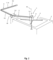
- a coupling device 1 for coupling an autonomous vehicle 2 to a patient transport device 3 is shown.
- the coupling device 1 has a connecting member 4 which is designed to fasten the coupling device 1 to the autonomous vehicle 2.
- the coupling device 1 comprises a first link 5 with a proximal end section 5.1 and an opposite distal end section 5.2, wherein the proximal end section 5.1 of the link 5 is rotatably mounted on the connecting member 4 by means of a rotary joint D of the coupling device 1.
- the coupling device 1 also comprises an angled Coupling rod 6 with a proximal leg 6.1 and a distal leg 6.2 arranged at an angle with respect to the longitudinal extension of the proximal leg 6.1, wherein the proximal leg 6.1 of the coupling rod 6 is pivotally mounted on the distal end section 5.2 of the handlebar 5 by means of a pivot joint S of the coupling device 1 and the distal leg 6.2 of the coupling rod 6 forms a connection section 7 for coupling the coupling device 1 to the patient transport device 3.
- the rotary joint D by means of which the proximal end section 5.1 of the handlebar 5 is rotatably mounted on the connecting member 4 of the coupling device 1, has in the case of the present embodiment a rotation axis A1, which in an arrangement of the coupling device 1 coupled to the autonomous vehicle 2, such as in Fig. 2 illustrated, is vertically aligned
- the pivot joint S by means of which the proximal leg 6.1 of the coupling rod 6 is pivotally mounted on the distal end section 5.1 of the handlebar 5, has a pivot axis A2 which is horizontally aligned in an arrangement of the coupling device 1 coupled to the autonomous vehicle 2.
- the swivel joint D and/or the swivel joint S can be designed to be lockable, freely rotatable in a non-locked manner, brakeable from a rotary movement and/or automatically drivable.
- the rotary joint D is designed to mount the proximal end section 5.1 of the handlebar 5 on the connecting member 4 of the coupling device 1 so as to be rotatable over at least 360 degrees.
- the pivot joint S is designed to pivotally mount the proximal leg 6.1 of the coupling rod 6 on the distal end section 5.2 of the handlebar 5 in a predetermined number of different pivot positions W1 to W4.
- the distal leg 6.2 of the angled coupling rod 6 can be designed to have both the connection section 7 and a handle section 7a, 3d (see in particular also Fig. 8 ) to form.
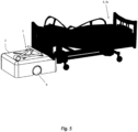
- Fig. 5 to Fig. 9 various possible systems are shown which can be put together individually, depending on the current requirement, using the coupling device 1 according to the invention. More precisely, this is the identical transport system, but in different configurations in order to be able to implement the various transport modes.
- the respective system for automatically moving a patient transport device 3 using an autonomous vehicle 2 has a patient transport device 3, an autonomous vehicle 2 and a coupling device 1 coupling the autonomous vehicle 2 to the patient transport device 3, according to one embodiment or according to several embodiments, as described in more detail below.
- the Fig. 5 shows a first embodiment of a system, comprising an autonomous vehicle 2, a coupling device 1 which couples the autonomous vehicle 2 to a patient transport device 3, wherein the patient transport device 3 is designed as a hospital bed 3a.
- the Fig. 6 shows a second embodiment of a system comprising an autonomous vehicle 2, a coupling device 1, which couples the autonomous vehicle 2 to a patient transport device 3, wherein the patient transport device 3 is designed as a wheelchair 3b.
- the Fig. 7 shows a third embodiment of a system, comprising an autonomous vehicle 2, a coupling device 1 which couples the autonomous vehicle 2 to a patient transport device 3, wherein the patient transport device 3 is designed as a rollator 3c.
- the Fig. 8 shows a fourth embodiment of a system comprising an autonomous vehicle 2, a coupling device 1 which is attached to the autonomous vehicle 2, wherein the coupling device 1 forms a handle portion 3d, 7 which can be grasped by a walking person 8.
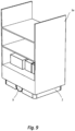
- the Fig. 9 shows a fifth embodiment of a system comprising an autonomous vehicle 2, a coupling device 1 which is attached to the autonomous vehicle 2 and brought into a hidden position such that the autonomous vehicle 2 can pick up and transport a hospital transport shelf 3e.
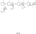
- the Fig. 10 illustrates the method for operating a system for automatically moving a patient transport device 3 by means of an autonomous vehicle 2, comprising a patient transport device 3, an autonomous vehicle 2 and a coupling device 1 coupling the autonomous vehicle 2 to the patient transport device 3, as described, wherein the distal leg 6.2 of the coupling rod 6 forms a connection section 7 for coupling the coupling device 1 to a patient transport device 3, wherein the connection section 7 is designed such that it is connected to its longitudinal extension follows a circular arc, comprising the step of automatically rotating the autonomous vehicle 2 by controlled driving of wheels 9 of the autonomous vehicle 2 such that the autonomous vehicle 2 rotates on a driving plane about a vertical axis of rotation, specifically about a vertical axis of rotation which runs through the circular arc center point determined by the circular arc of the longitudinal extension of the connecting section 7 of the coupling device 1 in the coupling position of the coupling device 1.
- the Fig. 10 illustrates the method for operating a system for automatically moving a patient transport device 3 by means of an autonomous vehicle 2, comprising a patient transport device 3, an autonomous vehicle 2 and a coupling device 1 coupling the autonomous vehicle 2 to the patient transport device 3, as described, comprising the steps of automatically rotating the autonomous vehicle 2 from its starting position by controlled driving of wheels 9 of the autonomous vehicle 2 such that the autonomous vehicle 2 rotates on a driving plane about a vertical axis of rotation that runs through the autonomous vehicle 2 until the autonomous vehicle 2 assumes a position in which it can be driven tangentially to a closed ring path encircling the patient transport device 3, then automatically driving the autonomous vehicle 2 along the ring path that surrounds the patient transport device 3 in a closed, circular manner such that a turning axis around which the patient transport device 3 rotates when the autonomous vehicle 2 moves along the ring path, through the patient transport device 3 until the patient transport device 3 is turned, and finally automatically turning the autonomous vehicle 2 again by controlled driving of Wheels 9 of the autonomous vehicle 2 such that the autonomous vehicle 2 rotate
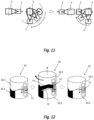
- the Fig. 12 shows a locking device 10 that can be integrated into the swivel joint S in order to form the swivel joint S so that the proximal leg 6.1 of the coupling rod 6 can be pivotally mounted on the distal end section 5.2 of the handlebar 5 in a predetermined number of different swivel positions.
- the respective joint can have the locking device 10, which is designed to lock the joint in question in a plurality of different joint angle positions, which in this respect form locking steps of the joint.
- the locking device 10 can for example have two claw coupling-like locking bodies 10.1 and 10.2, which have mutually facing end faces that have shape-complementing locking profiles P1, P2.
- a first locking body 10.1 and a second locking body 10.2 of the locking device 10 can be preloaded against each other with their end faces facing each other by means of a spring device 11.
Landscapes
- Engineering & Computer Science (AREA)
- Health & Medical Sciences (AREA)
- General Health & Medical Sciences (AREA)
- Robotics (AREA)
- Mechanical Engineering (AREA)
- Nursing (AREA)
- Life Sciences & Earth Sciences (AREA)
- Animal Behavior & Ethology (AREA)
- Public Health (AREA)
- Veterinary Medicine (AREA)
- Invalid Beds And Related Equipment (AREA)
Description
- Die Erfindung betrifft eine Kopplungsvorrichtung zum Ankoppeln eines autonomen Fahrzeugs an eine Patiententransportvorrichtung. Die Erfindung betrifft außerdem ein zugehöriges System und ein Verfahren zum Betreiben eines solchen Systems. Mittels der Kopplungsvorrichtung können nicht nur Module wie Rollstühle, Rollatoren oder Patientenbetten angekoppelt werden, sondern das System ermöglicht auch einen geführten Personentransport, bei dem sich eine eigenständig gehende Person an der Patiententransportvorrichtung festhalten kann.
- Die
WO 2016/192857 A2 beschreibt ein Robotersystem zum Transportieren eines verfahrbaren Gegenstands, insbesondere eines Krankenhausbettes, wobei das Robotersystem mindestens zwei Roboter umfasst und beide Roboter jeweils an den verfahrbaren Gegenstand, insbesondere an eine Koppeleinrichtung des verfahrbaren Gegenstands, derart koppelbar sind, dass eine Kraft von mindestens einem der Roboter auf den verfahrbaren Gegenstand übertragbar ist, so dass die Roboter gemeinsam den verfahrbaren Gegenstand transportieren können. - Die
US 2012029697 A1 offenbart eine robotische Transportvorrichtung mit einem Transportkörper und zwei Docking-Armen. Ferner ist ein Controller vorgesehen, durch den die Transportvorrichtung autonom bewegbar ist und sich einer Zielvorrichtung nähern kann, dessen Typ bestimmen und die zwei Docking-Arme entsprechend des Typs der Vorrichtung anpassen kann. Darüber hinaus weist die Transportvorrichtung Räder-Stopper auf, welche ebenfalls entsprechend des Typs der Vorrichtung eingestellt werden können. Eine entsprechend mit der Transportvorrichtung gekoppelte Zielvorrichtung kann dann autonom bewegt werden. - Die
EP 3283308 B1 zeigt ein robotisches Wagenzug-Vehikel, welches an einen Wagen, insbesondere Wäschewagen in einem Krankenhaus, andockbar ist und diesen ziehen kann. Hierfür weist das Vehikel einen Greifer zum Halten des Wagens auf. Ferner ist ein Positionierungssystem vorgesehen und ein oder mehrere Sensoren, um unnötige Kollisionen mit der Umgebung zu vermeiden. - Aufgabe der Erfindung ist es, eine Kopplungsvorrichtung zu schaffen, mit deren Hilfe eine Vielzahl an unterschiedlichen Patiententransportvorrichtungen auf einfache Weise wahlweise an dasselbe autonome Fahrzeug angekoppelt werden können. Die Aufgabe wird auch gelöst durch ein entsprechendes System, aufweisend eine Patiententransportvorrichtung, ein autonomes Fahrzeug und eine das autonome Fahrzeug an die Patiententransportvorrichtung koppelnde Kopplungsvorrichtung, und entsprechendes Verfahren zum Betreiben des Systems.
- Die Aufgabe wird gelöst durch eine Kopplungsvorrichtung zum Ankoppeln eines autonomen Fahrzeugs an eine Patiententransportvorrichtung, aufweisend:
- ein Anschlussglied, das ausgebildet ist zur Befestigung der Kopplungsvorrichtung an einem autonomen Fahrzeug,
- einen ersten Lenker mit einem proximalen Endabschnitt und einem gegenüberliegenden distalen Endabschnitt, wobei der proximale Endabschnitt des Lenkers mittels eines Drehgelenks der Kopplungsvorrichtung an dem Anschlussglied drehbar gelagert ist, und
- eine abgewinkelte Kopplungsstange mit einem proximalen Schenkel und einem gegenüber der Längserstreckung des proximalen Schenkels abgewinkelt angeordneten distalen Schenkel, wobei der proximale Schenkel der Kopplungsstange mittels eines Schwenkgelenks der Kopplungsvorrichtung an dem distalen Endabschnitt des Lenkers schwenkbar gelagert ist und der distale Schenkel der Kopplungsstange einen Anschlussabschnitt bildet, zum Ankoppeln der Kopplungsvorrichtung an eine Patiententransportvorrichtung.
- Die Kopplungsvorrichtung bildet ein weitgehend universelles Verbindungsmittel, um ein mobiles Fahrzeug wahlweise mit einer Vielzahl von unterschiedlichen Patiententransportvorrichtungen verbinden zu können, so dass das mobile Fahrzeug die jeweils momentan angekoppelte Patiententransportvorrichtung automatisch von einem ersten Ort zu einem zweiten Ort bewegen bzw. fahren kann.
- Im Rahmen der Erfindung werden auch Rollatoren, die eine Geh-Hilfe darstellen, bei denen die geführte Person selbsttätig geht, sich aber am Rollator abstützt als Patiententransportvorrichtungen verstanden. Im gleichen Sinne wird im Rahmen der Erfindung auch das autonome Fahrzeug selbst als eine Patiententransportvorrichtung verstanden, wenn die Kopplungsvorrichtung mit einem Handgriff verbunden ist oder die Kopplungsvorrichtung unmittelbar den Handgriff aufweist oder bildet, und eine selbsttätig gehende Person sich an dem Handgriff festhält und dadurch geführt und/oder gestützt wird. Insofern kann auch der Handgriff als die Patiententransportvorrichtung gelten. Als Patienten werden im Rahmen der Erfindung nicht nur kranke Personen verstanden, die sich in einem Krankenhaus befinden, sondern auch andere Personen, die sich beispielsweise in einer Rehabilitationsklinik, in einem Pflegeheim, an einem Alterswohnsitz oder zuhause befinden und einer entsprechenden Unterstützung bedürfen oder diese wünschen.
- Das autonome Fahrzeug kann ein Fahrwerk umfassen, so wie am Fahrwerk drehbar gelagerte Räder, von denen wenigstens ein Rad automatisch angetrieben ist. Das eine Rad oder die mehreren Räder können von einer Fahrsteuerung angesteuert werden. Mittels der Fahrsteuerung, die Teil des autonomen Fahrzeugs sein kann, wird das autonome Fahrzeug automatisch bewegt und insbesondere von einem ersten Ort zu einem zweiten Ort automatisch navigiert. Dazu kann die Fahrsteuerung mit einer Navigationssteuerung verbunden sein. Die Navigationssteuerung kann sich im autonomen Fahrzeug befinden oder sie kann separat ausgebildeter Teil eines vom autonomen Fahrzeug getrennten Navigationssystems sein. Im letzteren Fall ist die Fahrsteuerung steuerungstechnisch, insbesondere drahtlos mit dem Navigationssystem verbunden.
- Die Patiententransportvorrichtung kann beispielsweise ein Krankenbett, ein Rollstuhl oder ein Rollator sein.
- Im weiteren Sinne kann die Patiententransportvorrichtung aber auch lediglich ein Handgriff oder eine Haltestange sein, an der sich eine Person festhalten kann, um die Gefahr eines Stutzes zu reduzieren, wobei der Handgriff oder die Haltestange mittels dem autonomen Fahrzeug automatisch bewegt, d.h. verfahren wird, um die Person, welche sich an dem Handgriff oder der Haltestange festhält, automatisch von einem ersten Ort an einen zweiten Ort zu führen.
- Ergänzend kann ein autonomes Fahrzeug, welches die erfindungsgemäße Kopplungsvorrichtung aufweist, auch dazu genutzt werden, andere Transportvorrichtungen zu bewegen bzw. zu fahren. Einerseits kann in einem solchen Fall die Kopplungsvorrichtung in eine Verwahrungsposition gebracht werden, so dass sie ungenutzt bleibt, aber das autonome Fahrzeug beispielsweise ein Transportregal aufnehmen und es tragend fortbewegen kann. Andererseits kann die erfindungsgemäße Kopplungsvorrichtung alternativ auch genutzt werden, um das autonome Fahrzeug an das Transportregal anzukoppeln, so dass das autonome Fahrzeug das Transportregal in Art eines Anhängers ziehen kann. In diesem Fall müsste das Transportregal eigene Räder zum Fahren des Transportregals aufweisen, was im medizinischen Bereich, wie beispielsweise in Krankenhäusern regelmäßig der Fall ist.
- Das Anschlussglied, das ausgebildet ist zur Befestigung der Kopplungsvorrichtung an einem autonomen Fahrzeug, kann eingerichtet sein, die Kopplungsvorrichtung dauerhaft an dem autonomen Fahrzeug zu befestigen. Dann bildet das autonome Fahrzeug zusammen mit der Kopplungsvorrichtung eine Fahreinheit zum Anhängen einer Patiententransportvorrichtung. Das Anschlussglied kann aber auch manuell lösbar gestaltet sein, so dass die Kopplungsvorrichtung bei Bedarf von dem autonomen Fahrzeug getrennt bzw. wieder daran befestigt werden kann.
- Der erste Lenker ermöglicht ein Verstellen der Position des Schwenkgelenks relativ zum autonomen Fahrzeug, wenn die Kopplungsvorrichtung an dem autonomen Fahrzeug angeordnet ist. Diese Ausbildung ermöglicht es dem autonomen Fahrzeug außerdem, sich unter der Kopplungsvorrichtung um eine eigene vertikale Achse drehen zu können, ohne dass sich der Lenker und die Kopplungsstange mitdrehen.
- Der erste Lenker kann im einfachsten Fall von einer geraden Verbindungsstange gebildet werden. Gegebenenfalls kann der erste Lenker jedoch auch eine andere Gestalt aufweisen. Beispielsweise kann der erste Lenker eine gebogene Form aufweisen, oder einen Knickbereich oder mehrere Knickbereiche aufweisen. Der proximale Endabschnitt und der distale Endabschnitt definieren die beiden gegenüberliegenden Endabschnitte des jeweilig gestalteten Lenkers, unabhängig davon, wie der Lenker, bzw. ein Mittenabschnitt des Lenkers ausgebildet ist.
- Mit seinem proximalen Endabschnitt ist der Lenker über das Drehgelenk an dem Anschlussglied der Kopplungsvorrichtung drehbar gelagert. Als proximaler Endabschnitt wird derjenige Endabschnitt des Lenkers definiert, welcher in der kinematischen Kette von Drehgelenk und Schwenkgelenk sich näher an dem Anschlussglied bzw. im System sich näher an dem autonomen Fahrzeug befindet und sich weiter weg von dem Anschlussabschnitt der Kopplungsstange bzw. im System sich weiter weg von der Transportvorrichtung befindet. Als distaler Endabschnitt wird derjenige Endabschnitt des Lenkers definiert, welcher in der kinematischen Kette von Drehgelenk und Schwenkgelenk sich weiter weg von dem Anschlussglied bzw. im System sich weiter weg von dem autonomen Fahrzeug befindet und sich näher an dem Anschlussabschnitt der Kopplungsstange bzw. im System sich näher an der Transportvorrichtung befindet.
- Die abgewinkelte Kopplungsstange kann stumpfwinkelig oder spitzwinkelig ausgebildet sein. Im Speziellen kann die abgewinkelte Kopplungsstange rechtwinkelig ausgebildet sein, so dass der proximale Schenkel und der distale Schenkel zumindest in ihren Verbindungsbereichen zumindest annähernd in einem 90-Grad-Winkel aneinanderstoßen. Der proximale Schenkel und der distale Schenkel können jeweils von geraden Stangenabschnitten oder Rohrabschnitten gebildet werden. Alternativ können der proximale Schenkel und/oder der distale Schenkel jeweils von gebogenen, geschwungenen oder gekröpften Stangenabschnitten oder Rohrabschnitten gebildet werden.
- Als proximaler Schenkel wird derjenige Schenkel der Kopplungsstange definiert, welcher in der kinematischen Kette von Drehgelenk und Schwenkgelenk sich näher an dem Anschlussglied bzw. im System sich näher an dem autonomen Fahrzeug befindet und sich weiter weg von dem Anschlussabschnitt der Kopplungsstange bzw. im System sich weiter weg von der Transportvorrichtung befindet. Als distaler Schenkel wird derjenige Schenkel der Kopplungsstange definiert, welcher in der kinematischen Kette von Drehgelenk und Schwenkgelenk sich weiter weg von dem Anschlussglied bzw. im System sich weiter weg von dem autonomen Fahrzeug befindet und sich näher an dem Anschlussabschnitt der Kopplungsstange bzw. im System sich näher an der Transportvorrichtung befindet.
- Das Schwenkgelenk kann einen maximalen Schwenkwinkel aufweisen, der kleiner ist als 360 Grad, insbesondere kleiner ist als 180 Grad. Alternativ kann das Schwenkgelenk aber auch ausgebildet sein für Drehungen um mehr als 360 Grad bzw. zum freien Drehen. Insoweit kann auch das Schwenkgelenk als ein Drehgelenk ausgebildet sein.
- Das Drehgelenk kann ausgebildet sein für Drehungen um mehr als 360 Grad bzw. zum freien Drehen. Das Drehgelenk kann aber auch alternativ ausgebildet sein mit einem maximalen Drehwinkel, der kleiner ist als 360 Grad, insbesondere kleiner ist als 180 Grad. Insoweit kann auch das Drehgelenk als ein Schwenkgelenk ausgebildet sein.
- Die Kopplungsvorrichtung weist wenigstens das Drehgelenk und das Schwenkgelenk auf. In weiterführenden Ausgestaltungen kann die Kopplungsvorrichtung gegebenenfalls neben dem einem Drehgelenk und dem einen Schwenkgelenk noch ein weiteres Gelenk oder mehrere weitere Gelenke aufweisen.
- Der Anschlussabschnitt zum Ankoppeln der Kopplungsvorrichtung an eine Patiententransportvorrichtung kann bereits durch einen einfachen Stangenabschnitt oder Rohrabschnitt des distalen Schenkels gebildet werden. In einer solchen Ausführung kann der distale Schenkel der Kopplungsstange hinter einem Strukturelement der Transportvorrichtung eingehakt werden, beispielsweise hinter einem Fahrwerksrahmenteil eines Krankenbettes, eines Rollstuhles oder eines Rollators. Alternativ oder ergänzend kann der Anschlussabschnitt mechanische Verbindungsmittel aufweisen, mit denen die Kopplungsvorrichtung an der jeweiligen Transportvorrichtung befestigt werden kann. Die Verbindungsmittel können beispielsweise Klemmbacken, Greiferfinger, Haken oder ähnliche formschlüssige und/oder kraftschlüssige Verbindungsmittel sein.
- Das Drehgelenk, mittels dem der proximale Endabschnitt des Lenkers an dem Anschlussglied der Kopplungsvorrichtung drehbar gelagert ist, kann eine Drehachse aufweisen, welche in einer an das autonome Fahrzeug angekoppelten Anordnung der Kopplungsvorrichtung vertikal ausgerichtet ist, und das Schwenkgelenk, mittels dem der proximale Schenkel der Kopplungsstange an dem distalen Endabschnitt des Lenkers schwenkbar gelagert ist, kann dabei eine Schwenkachse aufweisen, welche in einer an das autonome Fahrzeug angekoppelten Anordnung der Kopplungsvorrichtung zumindest im Wesentlichen horizontal ausgerichtet ist.
- Indem die Drehachse des Drehgelenks vertikal ausgerichtet ist, kann die gesamte Kopplungsvorrichtung relativ zum autonomen Fahrzeug in verschiedene Himmelsrichtungen geschwenkt werden. Indem die Schwenkachse des Schwenkgelenks horizontal ausgerichtet ist, kann der Anschlussabschnitt der Kopplungsvorrichtung, insbesondere ein Griffabschnitt der Kopplungsvorrichtung in seiner jeweiligen Höhenlage verstellt d.h. angepasst werden.
- Das Drehgelenk kann somit eine Drehachse aufweisen, welche in einer an das autonome Fahrzeug angekoppelten Anordnung der Kopplungsvorrichtung in allen Fahrstellungen des autonomen Fahrzeugs auf einer horizontalen Fahrebene vertikal ausgerichtet ist, und das Schwenkgelenk kann dabei eine Schwenkachse aufweisen, welche in einer an das autonome Fahrzeug angekoppelten Anordnung der Kopplungsvorrichtung in all den möglichen Drehlagen des Drehgelenks und in allen Fahrstellungen des autonomen Fahrzeugs auf einer horizontalen Fahrebene stets horizontal ausgerichtet ist.
- Das Drehgelenk und/oder das Schwenkgelenk können arretierbar, in einer nicht-arretierten Weise frei drehbar, aus einer Drehbewegung bremsbar und/oder automatisch antreibbar ausgebildet sein.
- Für eine arretierbare Ausbildung des Drehgelenks und/oder des Schwenkgelenks kann das jeweilige Gelenk eine Rastvorrichtung aufweisen, welche ausgebildet ist, das betreffende Gelenk in mehreren verschiedenen Gelenkwinkelstellungen, die insoweit Raststufen des Gelenks bilden, einrastend zu arretieren. Die Rastvorrichtung kann dazu beispielsweise zwei klauenkupplungsartige Rastkörper aufweisen, welche aufeinander zuweisende Stirnseiten aufweisen, die formergänzende Rastprofile aufweisen. Ein erster Rastkörper und ein zweiter Rastkörper der Rastvorrichtung können dazu mit ihren Stirnseiten aufeinander zuweisend mittels einer Federeinrichtung gegeneinander vorgespannt sein. Abhängig von der Geometrie der Formpartner und der Federvorspannung das Gelenk auch als Sicherheitskupplung genutzt werden.
- Für eine bremsbare Ausbildung des Drehgelenks und/oder des Schwenkgelenks kann das jeweilige Gelenk eine Bremse aufweisen. Die jeweilige Bremse kann manuell zu betätigen sein oder automatisch aktivierbar und deaktivierbar ausgebildet sein. Im Fall einer automatisch aktivierbaren und deaktivierbaren Bremse kann diese beispielsweise eine elektromechanische Bremse sein.
- Für eine automatisch antreibbare Ausbildung des Drehgelenks und/oder des Schwenkgelenks kann das jeweilige Gelenk einen Motor, insbesondere einen elektrischen Motor aufweisen. Der elektrische Motor und/oder gegebenenfalls andere elektrische Komponenten der Kopplungsvorrichtung können über das autonome Fahrzeug mit elektrischer Energie versorgt werden. Die zur Versorgung mit elektrischer Energie erforderlichen elektrischen Kabel oder elektrischen Leitungen können insbesondere im Inneren der Kopplungsvorrichtung, beispielsweise in einem hohlen Rohr der Kopplungsvorrichtung verlegt und/oder geführt sein. Dazu kann die Kopplungsvorrichtung einen elektrischen Steckverbinder aufweisen, welcher mit einem elektrischen Gegensteckverbinder des autonomen Fahrzeugs zusammenwirkt, so dass elektrische Energie von dem autonomen Fahrzeug auf die Kopplungsvorrichtung übertragen werden kann, wenn die Kopplungsvorrichtung an dem autonomen Fahrzeug angebracht ist.
- Das Drehgelenk und/oder das Schwenkgelenk können automatisch arretierbar und/oder manuell arretierbar ausgebildet sein.
- Das Drehgelenk kann ausgebildet sein, den proximalen Endabschnitt des Lenkers an dem Anschlussglied der Kopplungsvorrichtung über wenigstens 360 Grad drehbar zu lagern.
- Das Schwenkgelenk kann ausgebildet sein, den proximalen Schenkel der Kopplungsstange an dem distalen Endabschnitt des Lenkers in einer vorbestimmten Anzahl von unterschiedlichen Schwenkstellungen arretierbar schwenkbar zu lagern. Der proximale Schenkel der Kopplungsstange kann mittels des Schwenkgelenks auch kontinuierlich verstellbar, d.h. stufenlos verstellbar und somit in beliebigen Stellungen arretierbar sein. In einer Leerfahrt-Stellung des autonomen Fahrzeugs kann die Kopplungsstange in einer Parkposition bzw. in einer Nische des autonomen Fahrzeugs, insbesondere zumindest teilweise oder vollständig verborgen, sich in einer Verwahrungsstellung befinden.
- Der distale Schenkel der abgewinkelten Kopplungsstange kann ausgebildet sein, sowohl einen Anschlussabschnitt, als auch einen Handgriffabschnitt zu bilden.
- Als ein Anschlussabschnitt kann dieser Verbindungsmittel aufweisen, beispielsweise Klemmbacken, Greiferfinger, Haken oder ähnliche formschlüssige und/oder kraftschlüssige Verbindungsmittel, um die Kopplungsvorrichtung mit der jeweiligen Patiententransportvorrichtung verbinden zu können.
- Das Drehgelenk kann eine erste Überlastsicherung aufweisen, die ausgebildet ist, das arretierte, das gebremste oder das angetriebene Drehgelenk drehmomentfrei zu schalten, wenn das übertragene Drehmoment ein vorbestimmtes Maximalmoment überschreitet und/oder das Schwenkgelenk kann eine zweite Überlastsicherung aufweisen, die ausgebildet ist, das arretierte, das gebremste oder das angetriebene Schwenkgelenk drehmomentfrei zu schalten, wenn das übertragene Drehmoment ein vorbestimmtes Maximalmoment überschreitet.
- Die Aufgabe wird demgemäß auch gelöst durch ein System zum automatischen Bewegen einer Patiententransportvorrichtung mittels eines autonomen Fahrzeugs, aufweisend eine Patiententransportvorrichtung, ein autonomes Fahrzeug und eine das autonome Fahrzeug an die Patiententransportvorrichtung koppelnde Kopplungsvorrichtung, nach einer Ausführungsform oder nach mehreren Ausführungsformen, wie beschrieben.
- Die Aufgabe wird auch gelöst durch ein Verfahren zum Betreiben eines Systems zum automatischen Bewegen einer Patiententransportvorrichtung mittels eines autonomen Fahrzeugs, aufweisend eine Patiententransportvorrichtung, ein autonomes Fahrzeug und eine das autonome Fahrzeug an die Patiententransportvorrichtung koppelnde Kopplungsvorrichtung, nach einer Ausführungsform oder nach mehreren Ausführungsformen, wie beschrieben, aufweisend die Schritte:
- automatisches Drehen des autonomen Fahrzeugs aus seiner Ausgangsstellung durch angesteuertes Antreiben von Rädern des autonomen Fahrzeugs derart, dass das autonome Fahrzeug sich auf einer Fahrebene um eine vertikale Drehachse dreht, die durch das autonome Fahrzeug verläuft, bis das autonome Fahrzeug eine Stellung einnimmt, in der es tangential zu einem um die Patiententransportvorrichtung umlaufenden geschlossenen Ringpfad fahrbar ist,
- automatisches Fahren des autonomen Fahrzeugs entlang des Ringpfades, der die Patiententransportvorrichtung geschlossen umlaufend umgibt, derart, dass eine Wendeachse oder Drehachse, um welche sich die Patiententransportvorrichtung dreht, wenn sich das autonome Fahrzeug entlang des Ringpfades bewegt, durch die Patiententransportvorrichtung verläuft, bis die Patiententransportvorrichtung gewendet oder gedreht ist,
- erneutes automatisches Drehen des autonomen Fahrzeugs durch angesteuertes Antreiben von Rädern des autonomen Fahrzeugs derart, dass das autonome Fahrzeug sich auf der Fahrebene um eine vertikale Drehachse dreht, die durch das autonome Fahrzeug verläuft, bis das autonome Fahrzeug eine Stellung einnimmt, in der es mit seiner Hauptfahrrichtung um eine zu seiner Ausgangsstellung um einen Winkel gedrehten oder um 180 Grad gewendeten Stellung ausgerichtet ist.
- Das Verfahren zum Betreiben eines Systems zum automatischen Bewegen einer Patiententransportvorrichtung mittels eines autonomen Fahrzeugs, kann eine Patiententransportvorrichtung, ein autonomes Fahrzeug und eine das autonome Fahrzeug an die Patiententransportvorrichtung koppelnde Kopplungsvorrichtung, nach einer Ausführungsform oder nach mehreren Ausführungsformen wie beschrieben aufweisen, wobei der distale Schenkel der Kopplungsstange einen Anschlussabschnitt bildet, zum Ankoppeln der Kopplungsvorrichtung an eine Patiententransportvorrichtung, wobei der Anschlussabschnitt derart ausgebildet ist, dass er mit seiner Längserstreckung einem Pfad, insbesondere Bogen oder einem Kreisbogen folgt, aufweisend den Schritt:
- automatisches Drehen des autonomen Fahrzeugs durch angesteuertes Antreiben von Rädern des autonomen Fahrzeugs derart, dass das autonome Fahrzeug sich auf einer Fahrebene um eine vertikale Drehachse dreht, und zwar um eine vertikale Drehachse welche durch den von dem Pfad, insbesondere Bogen oder Kreisbogen der Längserstreckung des Anschlussabschnitts der Kopplungsvorrichtung bestimmten Bogenmittelpunkt in der Ankopplungsstellung der Kopplungsvorrichtung verläuft.
- Die Erfindung ist im Folgenden zusammenfassend dargestellt und mitunter anders ausgedrückt nochmals in anderen Worten dargestellt. Die Erfindung stellt ein Konzept für eine Multimobilitätserweiterung von Patienten im Krankenhaus oder in Pflegeeinrichtungen durch die Automatisierung des Patiententransportes bereits, mit dem Zweck die Pflegekräfte zu entlasten, sodass sie mehr Zeit für die tatsächlichen pflegerischen Tätigkeiten zur Verfügung haben. Ein Vorteil dabei kann sein, dass ohne Modifizierung der zu transportierenden Patiententransportvorrichtungen, die nötigen Szenarien des Personentransportes umgesetzt werden können, inklusive des geführten Personentransportes, unabhängig von der Art beispielsweise des Rollators oder Rollstuhls. Durch eine geschickte Ausprägung der erfindungsgemäßen Kopplungsvorrichtung in Kombination mit einer mobilen Plattform, d.h. einem autonomen Fahrzeug, kann ein Gesamtsystem erstellt werden, welches die Szenarien ohne Umrüsten oder Anpassen erfüllen kann. Die nachfolgend beschriebene technische Lösung ist aufgebaut aus einer einfachen Kinematik, der Kopplungsvorrichtung, die in Kombination mit sinnvoller Ausnutzung der Flexibilität der mobilen Plattform auf geschickte Weise mit den Systemen koppeln kann und eine hohe Beweglichkeit für das Gesamtsystem bietet. Dies kann essentiell sein, da der zur Verfügung stehende Platz in den Pflegeeinrichtungen oder in Krankenhäusern begrenzt ist und Eigenschaften wie beispielsweise ein möglichst kleiner Wendekreis daher eine wichtige Rolle spielen.
- Zusammenfassend wird durch die vorgestellte Erfindung der Personentransport in den Szenarien des geführten Personentransports, einem Laufen des Patienten am Rollator, einem Sitzen des Patienten im Rollstuhl und einem Transport des Patienten, der sich liegend im Bett befindet, automatisiert.
- Dies wird ohne Modifizierung der zu bewegenden Module auf einfache Art und Weise mit einem einzigen System gelöst. Dadurch wird eine kostengünstige, effiziente Lösung für den Personentransport aufgezeigt und die Pflegekräfte entlastet, sodass mehr Zeit für die wesentlichen Aufgaben bleibt.
- Hauptbestandteil der Erfindung ist ein Koppelsystem, das für Patiententransport in verschiedenen Modi genutzt werden kann und für den Menschen ein Multimobilitätsmodul bietet. In Kombination mit einer differentiell angetriebenen mobilen Plattform und einer geschickten Anordnung des Koppelsystems zu der Plattform besitzt das Gesamtsystem eine hohe Flexibilität trotz einfacher Kinematik des eigentlichen Koppelmoduls. Ein weiterer Vorteil besteht darin, dass das System mit den verschiedenen Modulen koppelbar ist und somit flexibel kombiniert werden kann, sodass nur eine minimale Anzahl dieser Geräte benötigt wird, um die Mobilität und Flexibilität eine Vielzahl an Modulen mit dem Patienten zu ermöglichen.
- Nachfolgend wird auf die Hauptbestandteile und deren Ausprägung eingegangen. Fokus der Erfindung liegt in der Kopplungsvorrichtung, d.h. dem Koppelmodul, weshalb dessen Bestandteile genauer erläutert werden.
- Als mobile Plattform kann eine beliebige mobile Plattform mit differentiellem Antrieb genutzt werden, deren Spezifikationen den Anforderungen des Anwendungsfalls gerecht werden. Um ein schlüssiges Gesamtkonzept zu ermöglichen, kann es sinnvoll sein, dass die mobile Plattform beispielsweise mit Laserscannern und Kameras für die Sicherheit und Navigation ausgestattet ist, sowie weiter optional über einen Hubmechanismus verfügen kann, dessen Bewegung beispielsweise zum Anheben von Objekten oder Modulen oder als Antriebsorgan für einen Koppelmechanismus zwischen Koppelmodul und zu transportierendem Objekt herangezogen werden kann. Die mobile Plattform verfügt über die entsprechenden Spezifikationen für die Lasten, die zu handhaben sind und weist beispielsweise zwei Laserscanner und einen Hubmechanismus auf. Vorteil der hier vorgeschlagenen Konzepte liegen allerdings auch darin, dass durch den modularen Aufbau auch eine beliebige Plattform, welche die Anforderungen erfüllt, genutzt werden kann.
- Wie zuvor beschrieben besteht das Koppelmodul aus drei Hauptbestandteilen, welche jeweils eine oder mehrere Funktionen realisieren und im Zusammenspiel ein einfaches Koppelmodul mit einer Vielzahl an Funktionen und eine große Flexibilität bereitstellen, was für das Multimobilitätsmodul unabdingbar ist und die verschiedenen Transportmodi sinnvoll ermöglicht. Das Koppelmodul an sich ist einfach aufgebaut und nutzt die Freiheitsgrade der mobilen Plattform, um Funktionen zu realisieren, wodurch das System einen einfachen Aufbau aufweist, jedoch verschiedene Funktionen realisieren kann.
- Eine Deichselaufhängung kann das erste Gelenk der kinematischen Kette des Koppelmoduls ergänzen und dadurch gekennzeichnet, dass die Rotationsachse in einem 90°-Winkel die Achsen der Antriebsräder der mobilen Plattform schneidet. Die bekannten Fahrsysteme haben in der Regel einen großen Wendekreis. Die hier vorgestellte Anordnung der Achsen zueinander löst dieses technische Problem sinnvoll, indem der Wendekreis auf die minimal möglichen Abmessungen reduziert wird, in dem das zu ziehende Modul beim Wenden auf der Stelle gedreht werden kann. Ein minimaler Radius ergibt den Kollisionsradius des zu ziehenden Moduls beim Drehen auf der Stelle, addiert zu der Länge des Koppelmoduls und des Kollisionsradius beim Drehen auf der Stelle der mobilen Plattform.
- Eine 180° Wendung des Gesamtsystems auf engstem Raum erfolgt beispielsweise in drei hintereinander auszuführenden Einzelbewegungen. Zuerst dreht die mobile Plattform auf der Stelle um 90°, was durch den differentiellen Antrieb in Kombination mit dem Drehgelenk des Koppelmoduls möglich ist. Anschließend wird die mobile Plattform so angetrieben, dass es um das zu ziehende Modul herumfährt. Dies erfolgt so, dass der Drehpunkt des zu transportierenden Moduls genau in der Mitte der eigenen beiden Haupträder auf der Radachse liegt. Nachdem die mobile Plattform einen Halbkreis um das zu transportierende Module gefahren ist und dieses dadurch eine 180°-Drehung auf der Stelle durchgeführt hat, dreht die mobile Plattform auf der Stelle wieder um 90°, sodass die Hauptfahrrichtung nun 180° gedreht ist gegenüber der Plattformorientierung vor dem Wendemanöver und das Gesamtsystem die Fahr fortsetzen kann.
- Zusammenfassend ermöglichen das Gelenk und die geschickte Anordnung der Achse zur Antriebsachse der mobilen Plattform das Wenden des Gesamtsystems mit minimalem Platzbedarf.
- Weiterhin kann in dem Gelenk eine Bremse oder eine Verriegelung integriert sein, so dass die Relativbewegung zwischen mobiler Plattform und dem Koppelmodul gesperrt werden kann. Dies ist für eine Variante des Koppelns sinnvoll und wird nachfolgend näher beschrieben.
- Die Verriegelung des Gelenks kann automatisch oder manuell erfolgen. Für die Anwendung der Verriegelung für die Ausführung der Kopplungsmöglichkeit muss es lediglich möglich sein, das Gelenk in seiner Nullstellung verriegeln zu können. Dies kann neben einer Halte- oder Feststellbremse auch einfacher realisiert werden, beispielsweise mit einfachen Verriegelungsmechanismen oder Verriegelungspartnern, da keine großen Lasten in diesem Zustand übertragen werden müssen. Dies kann über eine kraftschlüssige und/oder formschlüssige Verbindung erfolgen.
- Möglichkeiten dazu sind beispielsweise eine Stiftverbindung, bei der ein Gelenkpartner einen Stift oder ein stiftähnliches Element aufweist, vorzugsweise konisch zulaufend, um geringe Abweichungen in der Gelenkausrichtung zu kompensieren und ein Verklemmen der Verbindung zu verhindern. Der andere Gelenkpartner weist den entsprechenden Gegenpart auf, beispielsweise eine Sacklochbohrung oder eine konisch zulaufende Bohrung. Anstatt Stift und Bohrung sind auch weitere Geometrien denkbar und sinnvoll, wie beispielsweise eine Verzahnung, eine Paarung von Kegel und Kugel oder eine Keilverbindung. Gelöst und wieder verriegelt werden kann die Verbindung entweder manuell mit der Hand oder automatisch. Für die automatische Auslösung kann der in der Plattform vorhandene Hubmechanismus genutzt werden. Dazu kann lediglich einer der Verbindungspartner an dem Fahrzeugrahmen und der andere Partner am Hubrahmen befestigt sein. Durch die Hubbewegung werden die Elemente zusammengefügt und dadurch verriegelt. So ist das Gelenk an sich betrachtet passiv, kann aber die Funktion des Hubes ausnutzen, um das Gelenk autonom zu sperren. Weite Möglichkeiten zur automatischen Betätigung sind z.B. Aktor-Elemente, kleine Linearantriebe oder Hubmagnete.
- Neben der Funktion, das Gelenk zu sperren, können bei Verwendung von Formelementen diese auch für eine Sicherheitsfunktion genutzt werden. Soll beispielsweise eine Koppelvorgang erfolgen und unerwarteter Weise eine Störkontur den Koppelvorgang verhindern, so wird die Verriegelung der Gelenkpartner automatisch bei Überlast gelöst. Dieser Grenzwert kann durch die Form der Gelenkpartner und die Normalkraft, die zum Koppeln aufgebracht wird, eingestellt werden. Erfolgt die Verriegelung manuell, kann die Vorspannkraft mittels Federelement eingestellt werden und durch Wahl der Federelemente die aufzubringende Kraft zum Lösen der Entkopplung gezielt eingestellt werden.
- Das zweite Gelenk der kinematischen Kette ist das Schwenkgelenk. Es kann drei oder eine beliebige Anzahl an wählbaren Hauptstellungen aufweisen. Diese vorzugsweise drei oder vier Stellungen ermöglichen auf sinnvolle Art und Weise die verschiedenen Szenarien (des Personen- und Modultransportes. Zwischenstellungen sind nicht notwendig, weshalb das Gelenk als tristabiles Gelenk ausgeführt sein kann. Dadurch werden eine einfache Aktorik und Ansteuerung des Gelenks ermöglicht.
- Die vorzugsweise drei Stellungen des Gelenks können kraft- und/oder formschlüssig realisiert werden und das Umstellen von einem Modus in den anderen kann manuell oder automatisch erfolgen.
- Ein manuelles Verstellen kann beispielsweise durch Lösen einer formschlüssigen Verbindung und/oder einer Vorspannung erfolgen. Nachdem das Glied des Koppelmoduls in die gewünschte Stellung verfahren wurde, kann die Verbindung wiederhergestellt werden und das System ist für das gewünschte Szenario einsatzbereit. Die Vorspannung kann beispielweise über ein Federelement erfolgen. Durch die Kombination einer Vorspannung und passender Formelemente der Gelenkpartner wird sichergestellt, dass immer eine der vorzugsweise drei Gelenkpositionen eingenommen wird, auch wenn die Stellung nicht exakt getroffen wurde. So sind geringe Abweichungen kompensierbar und das Umstellen kann schnell und manuell erfolgen.
- Eine weitere Möglichkeit ist ein Gelenk mit integriertem Gewinde, in das eine Schraube montiert werden kann. Wird die Schraube gelöst, kann das eine Glied relativ zum anderen Glied in die gewünschte Stellung bewegt werden. Durch Festziehen der Schraubverbindung werden die Teile wieder zusammengepresst und eine kraftschlüssige Verbindung hergestellt.
- Um die Modi automatisch zu wechseln, gibt es neben der Integration eines Motors, je nach Art des Motors in Kombination mit Getriebe, mit Bremse noch weitere Möglichkeiten, die Modi automatisch zu wechseln. Beispielsweise kann ein Draht aus einer Formgedächtnislegierung als Aktor verwendet werden. Mit einer Federvorspannung kann das eine Glied in der Mittelstellung gehalten werden. Soll nun der Modus gewechselt werden, wird je nachdem, in welche Richtung das Glied bewegt werden soll, eines von zwei gegeneinander wirkenden Formgedächtnis-Elemente bestromt, wodurch es materialbedingt aufgrund der Jouleschen Wärme kontrahiert und das Strukturteil entsprechend entgegen der Federvorspannung aus der Mittelstellung oder aus der neutralen Stellung auslenkt. Damit der Modus beibehalten wird, aber der Aktor nicht fortlaufend bestromt werden muss, können Formelementpartner vorgesehen werden, die dafür sorgen, dass das Gelenk an der gewünschten Stelle einrastet.
- Auf dem Strukturteil des Koppelbereichs des Koppelmoduls befinden sich die Funktionsflächen zum Koppeln mit den zu ziehenden Modulen, sowie die haptische Schnittstelle für die Patienten beim geführten Patiententransport. Der Koppelbereich ist dadurch gekennzeichnet, dass er mit den verschiedenen Modellen der Module wie Rollstuhl oder Rollator ohne Umrüsten koppeln kann. Eine mögliche Ausprägungsform ist eine gerade Stange, optional mit einem Schubelement, welches automatisch oder manuell an den Koppelpunkt des zu koppelnden Modules geschoben werden kann. Die eigentliche Verbindung zu der Tragstruktur des zu koppelnden Modules kann kraftschlüssig und/oder formschlüssig erfolgen. Dies kann über eine Schraubverbindung, Klemmverbindung oder Verriegelung erfolgen. Eine Geschickte Ausprägungsform des Koppelbereiches weist Koppelformelemente oder einen einfachen Mechanismus auf, welche sich mit der Tragstruktur der zu transportierenden Module verbinden können. Diese Koppelformelemente lassen sich öffnen und schließen. Diese Bewegungen können durch den Hub der mobilen Plattform ausgelöst werden, indem beispielsweise ein Seil oder ein Draht an dem Fahrzeugrahmen befestigt ist, und von dort aus am Hubrahmen und dem Koppelmodul entlang bis zu den Koppelformelementen geführt wird. Die Koppelformelemente können gelenkig gelagert und mit dem Seil oder dem Drahtelement verbunden sein. Wird nun der Hub der Plattform ausgelöst, schließen oder öffnen sich die Koppelformelemente aufgrund der Relativbewegung zwischen Hubrahmen und Fahrzeugrahmen der Plattform. So werden die Freiheitsgrade der mobilen Plattform sinnvoll genutzt und weitere Funktionen neben dem einfachen Anheben von Gütern gewährleistet.
- Eine weitere Möglichkeit der Ausprägungsform des Koppelbereiches ist eine gebogene Form. Diese Ausprägungsform weist zwei wesentliche Vorteile auf. In Kombination mit der Möglichkeit, das Gelenk zu sperren, kann die Bewegung der Plattform als Bewegung zum Koppeln genutzt werden. Dazu fährt die Plattform inklusive dem Koppelmodul vor das zu koppelnde Modul, verriegelt das Gelenk und dreht sich auf der Stelle oder entsprechend einer geeigneten Koppelbewegung. Dadurch bewegen sich Koppelmodul und die Plattform gemeinsam, relativ zu dem zu koppelnden Modul. Der Koppelbereich wird an der geeigneten Stelle des Moduls platziert und kann sich mit dem Strukturteil vom Modul verbinden. Danach wird das Gelenk freigegeben und der Transport kann durchgeführt werden. Der zweite Vorteil in der abgerundeten Geometrie des Koppelbereiches liegt in der Erhöhung der Ergonomie für den Patienten beim geführten Gehen. Der Koppelbereich kann so ausgeprägt sein, dass die haptische Verbindung für den Anwender ergonomisch ist und eine höhere Stabilität bietet, da durch die leicht gedrehten Handgelenke die Kraft vom Patienten besser auf das Koppelmodul übertragen werden kann und der Patient dadurch weniger angestrengt ist.
- Ein signifikanter Vorteil der geschickten Platzierung des Koppelbereiches in Bezug auf das zu koppelnde Modul liegt darin, dass die Geometrien der unterschiedlichen Rollstuhl- und Rollator-Modell stark variieren, allerdings in dem gewählten Koppelbereich in der Regel ähnlich aufgebaut und leicht zugänglich sind, weshalb diese besondere Anordnung vorteilhaft ist.
- Ein weiterer Vorteil des Koppelmoduls liegt in der geschickten geometrischen Form. Anstelle der Standardform einer Deichsel wird die hier vorgestellte Geometrie umgesetzt. Dadurch ist der Kraftfluss von Plattform zu dem zu koppelnden Modul zwar einfach und nicht über zwei Träger geführt, dafür wird allerdings eine gute Zugänglichkeit zu dem Patienten geboten, dieser hat genügend Beinfreiheit für einen komfortablen Transport und es ist außerdem möglich, ohne Kollision mit dem Koppelelement z.B. aus dem Rollstuhl aufzustehen.
- Es kann vorgesehen werden, dass die einzelnen Bereiche des Koppelmoduls in der Länge verstellbar sind, sodass sie ideal für den jeweiligen Modus manuell oder automatisch angepasst werden können. Alternativ kann aber auch eine Konfiguration ermittelt werden, welche alle Modi sinnvoll ermöglicht und das Koppelmodul dadurch einen einfacheren und robusteren Aufbau aufweist. Dazu müssen die Längen so aufeinander abgestimmt sein, dass alle Stellungen für die entsprechenden Modi mit der Koppelkinematik mit konstanten Gliedlängen ohne Kollision erreicht werden können. Die Längen müssen so gewählt werden, dass sich die Plattform um den eigenen Mittelpunkt drehen kann, ohne mit dem zu transportierenden Modul oder der Person zu kollidieren. Außerdem muss die Länge so ausgelegt sein, dass für den Modus eine ergonomische Höhe für den Patienten zum Festhalten gewährleistet ist.
- Damit überprüft werden kann, ob und wie der Patient sich im Gesamtsystem verhält und beispielsweise die Vorschubgeschwindigkeit und optional auch die Richtung, in die sich das System bewegt, eingestellt werden kann, können an verschiedenen Stellen des Koppelmoduls Sensorelemente integriert werden. Sie können in der Lagerung der Deichsel, in der Befestigungselement für Rollator und/oder Rollstuhl oder in einem Element des Koppelmoduls integriert werden. Entscheidend ist, dass in jedem Modus die Kraft zwischen zu transportierendem Modul, der geführten Person oder dem Bett detektiert werden kann. Als Sensorelement können kostengünstige Kraftsensoren, Dehnungsmessstreifen oder Wägezellen verwendet werden.
- Mit dem vorgestellten Koppelmodul ist es möglich, eine Vielzahl an unterschiedlichen Rollstühlen, Rollatoren und optional sogar Betten oder Trolleys koppeln und transportieren zu können. Außerdem verfügt das Koppelmodul über eine haptische Schnittstelle, sodass diese als Griff des Gesamtsystems betrachtet werden kann und als Stütze für den geführten Personentransport dienen kann.
- Um zu überwachen, ob und wie der Patient und/oder das Modul dem System folgen, kann ein Patientenüberwachungsmodul auf der Plattform vorgesehen werden. Dadurch können auch Gesten und Körperhaltung der Patienten überwacht und ggfs. für eine erfolgreiche weitere Behandlung analysiert und ausgewertet werden.
- Optional können neben dem Patiententransport auch Hol- und Bringdienste mit dem System ermöglicht werden. In diesem Fall koppelt das System beispielsweise an einen Trolley an und kann diesen autonom transportieren. Die Kopplung kann entweder durch den Hubmechanismus der Plattform oder mittels Bewegung der Plattform und dem verriegelten Gelenk erfolgen.
- Ein konkretes Ausführungsbeispiel der Erfindung ist in der nachfolgenden Beschreibung unter Bezugnahme auf die beigefügten Figuren näher erläutert. Konkrete Merkmale dieses exemplarischen Ausführungsbeispiels können unabhängig davon, in welchem konkreten Zusammenhang sie erwähnt sind, gegebenenfalls auch einzeln oder in weiteren Kombinationen betrachtet, allgemeine Merkmale der Erfindung darstellen.
- Es zeigen:
- Fig. 1
- eine perspektivische Darstellung auf Konzeptebene einer beispielhaften Ausführungsform einer erfindungsgemäßen Kopplungsvorrichtung zum Ankoppeln eines autonomen Fahrzeugs an eine Patiententransportvorrichtung,
- Fig. 2
- eine perspektivische Darstellung der Kopplungsvorrichtung gemäß
Fig. 1 in ihrer Anbaulage an einem beispielhaften autonomen Fahrzeug, - Fig. 3
- eine Teilansicht eines distalen Schenkels einer abgewinkelten Kopplungsstange der Kopplungsvorrichtung gemäß
Fig. 1 , - Fig. 4
- eine Draufsicht auf die Kopplungsvorrichtung gemäß
Fig. 1 in einer Alleinstellung, - Fig. 5
- eine erste Ausführungsvariante eines Systems, aufweisend ein autonomes Fahrzeug, eine Kopplungsvorrichtung, die das autonome Fahrzeug an eine Patiententransportvorrichtung koppelt, sowie die Patiententransportvorrichtung, die als ein Krankenbett ausgebildet ist,
- Fig. 6
- eine zweite Ausführungsvariante eines Systems, aufweisend ein autonomes Fahrzeug, eine Kopplungsvorrichtung, die das autonome Fahrzeug an eine Patiententransportvorrichtung koppelt, sowie die Patiententransportvorrichtung, die als ein Rollstuhl ausgebildet ist,
- Fig. 7
- eine dritte Ausführungsvariante eines Systems, aufweisend ein autonomes Fahrzeug, eine Kopplungsvorrichtung, die das autonome Fahrzeug an eine Patiententransportvorrichtung koppelt, sowie die Patiententransportvorrichtung, die als ein Rollator ausgebildet ist,
- Fig. 8
- eine vierte Ausführungsvariante eines Systems, aufweisend ein autonomes Fahrzeug, eine Kopplungsvorrichtung, die an dem autonome Fahrzeug befestigt ist, wobei die Kopplungsvorrichtung einen Handgriffabschnitt bildet, der von einer gehenden Person gegriffen werden kann,
- Fig. 9
- eine fünfte Ausführungsvariante eines Systems, aufweisend ein autonomes Fahrzeug, eine Kopplungsvorrichtung, die an dem autonome Fahrzeug befestigt und in eine verborgene Stellung gebracht ist, derart, dass das autonome Fahrzeug ein Krankenhaus-Transportregal aufnehmen und transportieren kann,
- Fig. 10
- eine schematische Darstellung, eines beispielshaften Verfahrens zum Ankoppeln des autonomen Fahrzeugs an eine Patiententransportvorrichtung,
- Fig. 11
- eine schematische Darstellung, eines beispielshaften Verfahrens zum Wenden des Systemgespanns, bestehend aus dem autonomen Fahrzeug, der Kopplungsvorrichtung und einer Patiententransportvorrichtung, und
- Fig. 12
- perspektivische Darstellungen einer Kupplung, welche das Schwenkgelenk der Kopplungsvorrichtung ausbildet zum Arretieren in vorbestimmten Schenkstellungen.
- In der
Fig. 1 ist eine Kopplungsvorrichtung 1 zum Ankoppeln eines autonomen Fahrzeugs 2 an eine Patiententransportvorrichtung 3 dargestellt. Die Kopplungsvorrichtung 1 weist ein Anschlussglied 4 auf, das ausgebildet ist zur Befestigung der Kopplungsvorrichtung 1 an dem autonomen Fahrzeug 2. Die Kopplungsvorrichtung 1 umfasst einen ersten Lenker 5 mit einem proximalen Endabschnitt 5.1 und einem gegenüberliegenden distalen Endabschnitt 5.2, wobei der proximale Endabschnitt 5.1 des Lenkers 5 mittels eines Drehgelenks D der Kopplungsvorrichtung 1 an dem Anschlussglied 4 drehbar gelagert ist. Die Kopplungsvorrichtung 1 umfasst außerdem eine abgewinkelte Kopplungsstange 6 mit einem proximalen Schenkel 6.1 und einem gegenüber der Längserstreckung des proximalen Schenkels 6.1 abgewinkelt angeordneten distalen Schenkel 6.2, wobei der proximale Schenkel 6.1 der Kopplungsstange 6 mittels eines Schwenkgelenks S der Kopplungsvorrichtung 1 an dem distalen Endabschnitt 5.2 des Lenkers 5 schwenkbar gelagert ist und der distale Schenkel 6.2 der Kopplungsstange 6 einen Anschlussabschnitt 7 bildet, zum Ankoppeln der Kopplungsvorrichtung 1 an die Patiententransportvorrichtung 3. - Das Drehgelenk D, mittels dem der proximale Endabschnitt 5.1 des Lenkers 5 an dem Anschlussglied 4 der Kopplungsvorrichtung 1 drehbar gelagert ist, weist im Falle des vorliegenden Ausführungsbeispiels eine Drehachse A1 auf, welche in einer an das autonome Fahrzeug 2 angekoppelten Anordnung der Kopplungsvorrichtung 1, wie beispielsweise in
Fig. 2 veranschaulicht, vertikal ausgerichtet ist, und das Schwenkgelenk S, mittels dem der proximale Schenkel 6.1 der Kopplungsstange 6 an dem distalen Endabschnitt 5.1 des Lenkers 5 schwenkbar gelagert ist, eine Schwenkachse A2 aufweist, welche in einer an das autonome Fahrzeug 2 angekoppelten Anordnung der Kopplungsvorrichtung 1 horizontal ausgerichtet ist.
das Drehgelenk D und/oder das Schwenkgelenk S können arretierbar, in einer nicht-arretierten Weise frei drehbar, aus einer Drehbewegung bremsbar und/oder automatisch antreibbar ausgebildet sein. - Im Falle des vorliegenden Ausführungsbeispiels ist das Drehgelenk D ausgebildet, den proximalen Endabschnitt 5.1 des Lenkers 5 an dem Anschlussglied 4 der Kopplungsvorrichtung 1 über wenigstens 360 Grad drehbar zu lagern.
- Im Falle des vorliegenden Ausführungsbeispiels ist das Schwenkgelenk S ausgebildet, den proximalen Schenkel 6.1 der Kopplungsstange 6 an dem distalen Endabschnitt 5.2 des Lenkers 5 in einer vorbestimmten Anzahl von unterschiedlichen Schwenkstellungen W1 bis W4 arretierbar schwenkbar zu lagern.
- Der distale Schenkel 6.2 der abgewinkelten Kopplungsstange 6 kann ausgebildet sein, sowohl den Anschlussabschnitt 7, als auch einen Handgriffabschnitt 7a, 3d (siehe insbesondere auch
Fig. 8 ) zu bilden. - In
Fig. 5 bis Fig. 9 sind verschiedene mögliche Systeme aufgezeigt, die mittels der erfindungsgemäßen Kopplungsvorrichtung 1 wahlweise individuell, je nach momentaner Anforderung, zusammengestellt werden können. Genauer gesagt handelt es sich dabei um das identische Transportsystem, jedoch in unterschiedlichen Konfigurationen, um die verschiedenen Transportmodi umsetzen zu können. Das jeweilige System zum automatischen Bewegen einer Patiententransportvorrichtung 3 mittels eines autonomen Fahrzeugs 2, weist eine Patiententransportvorrichtung 3, ein autonomes Fahrzeug 2 und eine das autonome Fahrzeug 2 an die Patiententransportvorrichtung 3 koppelnde Kopplungsvorrichtung 1, nach einer Ausführungsform oder nach mehreren Ausführungsformen, wie im Folgenden näher beschrieben auf. - Die
Fig. 5 zeigt eine erste Ausführungsvariante eines Systems, aufweisend ein autonomes Fahrzeug 2, eine Kopplungsvorrichtung 1, die das autonome Fahrzeug 2 an eine Patiententransportvorrichtung 3 koppelt, wobei die Patiententransportvorrichtung 3 als ein Krankenbett 3a ausgebildet ist. - Die
Fig. 6 zeigt eine zweite Ausführungsvariante eines Systems, aufweisend ein autonomes Fahrzeug 2, eine Kopplungsvorrichtung 1, die das autonome Fahrzeug 2 an eine Patiententransportvorrichtung 3 koppelt, wobei die Patiententransportvorrichtung 3 als ein Rollstuhl 3b ausgebildet ist. - Die
Fig. 7 zeigt eine dritte Ausführungsvariante eines Systems, aufweisend ein autonomes Fahrzeug 2, eine Kopplungsvorrichtung 1, die das autonome Fahrzeug 2 an eine Patiententransportvorrichtung 3 koppelt, wobei die Patiententransportvorrichtung 3 als ein Rollator 3c ausgebildet ist. - Die
Fig. 8 zeigt eine vierte Ausführungsvariante eines Systems, aufweisend ein autonomes Fahrzeug 2, eine Kopplungsvorrichtung 1, die an dem autonome Fahrzeug 2 befestigt ist, wobei die Kopplungsvorrichtung 1 einen Handgriffabschnitt 3d, 7 bildet, der von einer gehenden Person 8 gegriffen werden kann. - Die
Fig. 9 zeigt eine fünfte Ausführungsvariante eines Systems, aufweisend ein autonomes Fahrzeug 2, eine Kopplungsvorrichtung 1, die an dem autonome Fahrzeug 2 befestigt und in eine verborgene Stellung gebracht ist, derart, dass das autonome Fahrzeug 2 ein Krankenhaus-Transportregal 3e aufnehmen und transportieren kann. - Die
Fig. 10 veranschaulicht das Verfahren zum Betreiben eines Systems zum automatischen Bewegen einer Patiententransportvorrichtung 3 mittels eines autonomen Fahrzeugs 2, aufweisend eine Patiententransportvorrichtung 3, ein autonomes Fahrzeug 2 und eine das autonome Fahrzeug 2 an die Patiententransportvorrichtung 3 koppelnde Kopplungsvorrichtung 1, wie beschrieben, wobei der distale Schenkel 6.2 der Kopplungsstange 6 einen Anschlussabschnitt 7 bildet, zum Ankoppeln der Kopplungsvorrichtung 1 an eine Patiententransportvorrichtung 3, wobei der Anschlussabschnitt 7 derart ausgebildet ist, dass er mit seiner Längserstreckung einem Kreisbogen folgt, aufweisend den Schritt des automatischen Drehens des autonomen Fahrzeugs 2 durch angesteuertes Antreiben von Rädern 9 des autonomen Fahrzeugs 2 derart, dass das autonome Fahrzeug 2 sich auf einer Fahrebene um eine vertikale Drehachse dreht, und zwar um eine vertikale Drehachse welche durch den von dem Kreisbogen der Längserstreckung des Anschlussabschnitts 7 der Kopplungsvorrichtung 1 bestimmten Kreisbogenmittelpunkt in der Ankopplungsstellung der Kopplungsvorrichtung 1 verläuft. - Die
Fig. 10 veranschaulicht das Verfahren zum Betreiben eines Systems zum automatischen Bewegen einer Patiententransportvorrichtung 3 mittels eines autonomen Fahrzeugs 2, aufweisend eine Patiententransportvorrichtung 3, ein autonomes Fahrzeug 2 und eine das autonome Fahrzeug 2 an die Patiententransportvorrichtung 3 koppelnde Kopplungsvorrichtung 1, wie beschrieben, aufweisend die Schritte des automatischen Drehens des autonomen Fahrzeugs 2 aus seiner Ausgangsstellung durch angesteuertes Antreiben von Rädern 9 des autonomen Fahrzeugs 2 derart, dass das autonome Fahrzeug 2 sich auf einer Fahrebene um eine vertikale Drehachse dreht, die durch das autonome Fahrzeug 2 verläuft, bis das autonome Fahrzeug 2 eine Stellung einnimmt, in der es tangential zu einem um die Patiententransportvorrichtung 3 umlaufenden geschlossenen Ringpfad fahrbar ist, anschließend automatisches Fahren des autonomen Fahrzeugs 2 entlang des Ringpfades, der die Patiententransportvorrichtung 3 geschlossen umlaufend umgibt, derart, dass eine Wendeachse, um welche sich die Patiententransportvorrichtung 3 dreht, wenn sich das autonome Fahrzeug 2 entlang des Ringpfades bewegt, durch die Patiententransportvorrichtung 3 verläuft, bis die Patiententransportvorrichtung 3 gewendet ist, und abschließendes erneutes automatisches Drehen des autonomen Fahrzeugs 2 durch angesteuertes Antreiben von Rädern 9 des autonomen Fahrzeugs 2 derart, dass das autonome Fahrzeug 2 sich auf der Fahrebene um eine vertikale Drehachse dreht, die durch das autonome Fahrzeug 2 verläuft, bis das autonome Fahrzeug 2 eine Stellung einnimmt, in der es mit seiner Hauptfahrrichtung um eine zu seiner Ausgangsstellung um 180 Grad gewendeten Stellung, oder in einer beliebigen anderen Orientierung ausgerichtet ist. - Die
Fig. 12 zeigt eine Rastvorrichtung 10, die in das Schwenkgelenk S integriert sein kann, um das Schwenkgelenk S auszubilden, den proximalen Schenkel 6.1 der Kopplungsstange 6 an dem distalen Endabschnitt 5.2 des Lenkers 5 in einer vorbestimmten Anzahl von unterschiedlichen Schwenkstellungen arretierbar schwenkbar lagern zu können. Für eine arretierbare Ausbildung des Drehgelenks D und/oder des Schwenkgelenks S kann das jeweilige Gelenk die Rastvorrichtung 10 aufweisen, welche ausgebildet ist, das betreffende Gelenk in mehreren verschiedenen Gelenkwinkelstellungen, die insoweit Raststufen des Gelenks bilden, einrastend zu arretieren. Die Rastvorrichtung 10 kann dazu beispielsweise zwei klauenkupplungsartige Rastkörper 10.1 und 10.2 aufweisen, welche aufeinander zuweisende Stirnseiten aufweisen, die formergänzende Rastprofile P1, P2 aufweisen. Ein erster Rastkörper 10.1 und ein zweiter Rastkörper 10.2 der Rastvorrichtung 10 können dazu mit ihren Stirnseiten aufeinander zuweisend mittels einer Federeinrichtung 11 gegeneinander vorgespannt sein.
Claims (11)
- Kopplungsvorrichtung zum Ankoppeln eines autonomen Fahrzeugs (2) an eine Patiententransportvorrichtung (3), gekennzeichnet durch:- ein Anschlussglied (4), das ausgebildet ist zur Befestigung der Kopplungsvorrichtung (1) an einem autonomen Fahrzeug (2),- einen ersten Lenker (5) mit einem proximalen Endabschnitt (5.1) und einem gegenüberliegenden distalen Endabschnitt (5.2), wobei der proximale Endabschnitt (5.1) des Lenkers (5) mittels eines Drehgelenks (D) der Kopplungsvorrichtung (1) an dem Anschlussglied (4) drehbar gelagert ist, und- eine abgewinkelte Kopplungsstange (6) mit einem proximalen Schenkel (6.1) und einem gegenüber der Längserstreckung des proximalen Schenkels (6.1) abgewinkelt angeordneten distalen Schenkel (6.2), wobei der proximale Schenkel (6.1) der Kopplungsstange (6) mittels eines Schwenkgelenks (S) der Kopplungsvorrichtung (1) an dem distalen Endabschnitt (5.2) des Lenkers (5) schwenkbar gelagert ist und der distale Schenkel (6.2) der Kopplungsstange (6) einen Anschlussabschnitt (7) bildet, zum Ankoppeln der Kopplungsvorrichtung (1) an eine Patiententransportvorrichtung (3).
- Kopplungsvorrichtung nach Anspruch 1, dadurch gekennzeichnet, dass das Drehgelenk (D), mittels dem der proximale Endabschnitt (5.1) des Lenkers (5) an dem Anschlussglied (4) der Kopplungsvorrichtung (1) drehbar gelagert ist, eine Drehachse (A1) aufweist, welche in einer an das autonome Fahrzeug (2) angekoppelten Anordnung der Kopplungsvorrichtung (1) vertikal ausgerichtet ist, und das Schwenkgelenk (S), mittels dem der proximale Schenkel (6.1) der Kopplungsstange (6) an dem distalen Endabschnitt (5.2) des Lenkers (5) schwenkbar gelagert ist, eine Schwenkachse (A2) aufweist, welche in einer an das autonome Fahrzeug (2) angekoppelten Anordnung der Kopplungsvorrichtung (1) zumindest im Wesentlichen horizontal ausgerichtet ist.
- Kopplungsvorrichtung nach Anspruch 1 oder 2, dadurch gekennzeichnet, dass das Drehgelenk (D) und/oder das Schwenkgelenk (S) arretierbar, in einer nicht-arretierten Weise frei drehbar, aus einer Drehbewegung bremsbar und/oder automatisch antreibbar ausgebildet ist.
- Kopplungsvorrichtung nach einem der Ansprüche 1 bis 3, dadurch gekennzeichnet, dass das Drehgelenk (D) und/oder das Schwenkgelenk (S) automatisch arretierbar und/oder manuell arretierbar ausgebildet ist.
- Kopplungsvorrichtung nach einem der Ansprüche 1 bis 4, dadurch gekennzeichnet, dass das Drehgelenk (D) ausgebildet ist, den proximalen Endabschnitt (5.1) des Lenkers (5) an dem Anschlussglied (4) der Kopplungsvorrichtung (1) über wenigstens 360 Grad drehbar zu lagern.
- Kopplungsvorrichtung nach einem der Ansprüche 1 bis 5, dadurch gekennzeichnet, dass das Schwenkgelenk (S) ausgebildet ist, den proximalen Schenkel (6.1) der Kopplungsstange (6) an dem distalen Endabschnitt (5.2) des Lenkers (5) in einer vorbestimmten Anzahl von unterschiedlichen Schwenkstellungen arretierbar schwenkbar zu lagern.
- Kopplungsvorrichtung nach einem der Ansprüche 1 bis 6, dadurch gekennzeichnet, dass der distale Schenkel (6.2) der abgewinkelten Kopplungsstange (6) ausgebildet ist, sowohl einen Anschlussabschnitt (7), als auch einen Handgriffabschnitt (7a) zu bilden.
- Kopplungsvorrichtung nach einem der Ansprüche 1 bis 7, dadurch gekennzeichnet, dass das Drehgelenk (D) eine erste Überlastsicherung aufweist, die ausgebildet ist, das arretierte, das gebremste oder das angetriebene Drehgelenk (D) drehmomentfrei zu schalten, wenn das übertragene Drehmoment ein vorbestimmtes Maximalmoment überschreitet und/oder das Schwenkgelenk (S) eine zweite Überlastsicherung aufweist, die ausgebildet ist, das arretierte, das gebremste oder das angetriebene Schwenkgelenk (S) drehmomentfrei zu schalten, wenn das übertragene Drehmoment ein vorbestimmtes Maximalmoment überschreitet.
- System zum automatischen Bewegen einer Patiententransportvorrichtung (3) mittels eines autonomen Fahrzeugs (2), aufweisend eine Patiententransportvorrichtung (3), ein autonomes Fahrzeug (2) und eine das autonome Fahrzeug (2) an die Patiententransportvorrichtung (3) koppelnde Kopplungsvorrichtung (1) nach einem der Ansprüche 1 bis 8.
- Verfahren zum Betreiben eines Systems nach Anspruch 9, gekennzeichnet durch die Schritte:- automatisches Drehen des autonomen Fahrzeugs (2) aus seiner Ausgangsstellung durch angesteuertes Antreiben von Rädern (9) des autonomen Fahrzeugs (2) derart, dass das autonome Fahrzeug (2) sich auf einer Fahrebene um eine vertikale Drehachse dreht, die durch das autonome Fahrzeug (2) verläuft, bis das autonome Fahrzeug (2) eine Stellung einnimmt, in der es tangential zu einem um die Patiententransportvorrichtung (3) umlaufenden geschlossenen Ringpfad fahrbar ist,- automatisches Fahren des autonomen Fahrzeugs (2) entlang des Ringpfades, der die Patiententransportvorrichtung (3) geschlossen umlaufend umgibt, derart, dass eine Wendeachse oder Drehachse, um welche sich die Patiententransportvorrichtung (3) dreht, wenn sich das autonome Fahrzeug (2) entlang des Ringpfades bewegt, durch die Patiententransportvorrichtung (3) verläuft, bis die Patiententransportvorrichtung (3) gewendet oder gedreht ist,- erneutes automatisches Drehen des autonomen Fahrzeugs (2) durch angesteuertes Antreiben von Rädern (9) des autonomen Fahrzeugs (2) derart, dass das autonome Fahrzeug (2) sich auf der Fahrebene um eine vertikale Drehachse dreht, die durch das autonome Fahrzeug (2) verläuft, bis das autonome Fahrzeug (2) eine Stellung einnimmt, in der es mit seiner Hauptfahrrichtung um eine zu seiner Ausgangsstellung um einen Winkel gedrehten oder um 180 Grad gewendeten Stellung ausgerichtet ist.
- Verfahren zum Betreiben eines Systems nach Anspruch 9, dadurch gekennzeichnet, dass der distale Schenkel (6.2) der Kopplungsstange (6) einen Anschlussabschnitt (7) bildet, zum Ankoppeln der Kopplungsvorrichtung (1) an eine Patiententransportvorrichtung (3), wobei der Anschlussabschnitt (7) derart ausgebildet ist, dass er mit seiner Längserstreckung einem Pfad, insbesondere Bogen oder einem Kreisbogen folgt, aufweisend den Schritt:- automatisches Drehen des autonomen Fahrzeugs (2) durch angesteuertes Antreiben von Rädern (9) des autonomen Fahrzeugs (2) derart, dass das autonome Fahrzeug (2) sich auf einer Fahrebene um eine vertikale Drehachse dreht, und zwar um eine vertikale Drehachse welche durch den von dem einem Pfad, insbesondere Bogen oder Kreisbogen der Längserstreckung des Anschlussabschnitts (7) der Kopplungsvorrichtung (1) bestimmten Bogenmittelpunkt in der Ankopplungsstellung der Kopplungsvorrichtung (1) verläuft.
Applications Claiming Priority (2)
| Application Number | Priority Date | Filing Date | Title |
|---|---|---|---|
| DE102020215206.3A DE102020215206A1 (de) | 2020-12-02 | 2020-12-02 | Kopplungsvorrichtung, System mit einem autonomen Fahrzeug und einer Patiententransportvorrichtung, sowie Verfahren zum Betreiben eines solchen Systems |
| PCT/EP2021/083312 WO2022117488A1 (de) | 2020-12-02 | 2021-11-29 | Kopplungsvorrichtung, system mit einem autonomen fahrzeug und einer patiententransportvorrichtung, sowie verfahren zum betreiben eines solchen systems |
Publications (2)
| Publication Number | Publication Date |
|---|---|
| EP4255698A1 EP4255698A1 (de) | 2023-10-11 |
| EP4255698B1 true EP4255698B1 (de) | 2024-11-20 |
Family
ID=79170987
Family Applications (1)
| Application Number | Title | Priority Date | Filing Date |
|---|---|---|---|
| EP21835164.1A Active EP4255698B1 (de) | 2020-12-02 | 2021-11-29 | Kopplungsvorrichtung, system mit einem autonomen fahrzeug und einer patiententransportvorrichtung, sowie verfahren zum betreiben eines solchen systems |
Country Status (3)
| Country | Link |
|---|---|
| EP (1) | EP4255698B1 (de) |
| DE (1) | DE102020215206A1 (de) |
| WO (1) | WO2022117488A1 (de) |
Families Citing this family (1)
| Publication number | Priority date | Publication date | Assignee | Title |
|---|---|---|---|---|
| DE102023212330A1 (de) * | 2023-12-07 | 2025-06-12 | Robert Bosch Gesellschaft mit beschränkter Haftung | Positionierungsmodul für fahrerlose Transportsysteme |
Family Cites Families (9)
| Publication number | Priority date | Publication date | Assignee | Title |
|---|---|---|---|---|
| US8165718B2 (en) * | 2010-07-30 | 2012-04-24 | Toyota Motor Engineering & Manufacturing North America, Inc. | Robotic transportation devices and systems |
| US10213354B2 (en) | 2014-09-18 | 2019-02-26 | Ideassociates (Iom) Limited | Wheeled Transportation device |
| DK178498B1 (en) * | 2015-04-13 | 2016-04-18 | Mobile Ind Robots Aps | ROBOT-BASED VEHICLE TO TOUGH A CAR |
| EP3302894B1 (de) | 2015-06-05 | 2023-04-26 | Thomas Buck | Robotergestütztes transportieren eines verfahrbaren gegenstands |
| DE102016014566B4 (de) | 2016-12-07 | 2019-03-14 | Grenzebach Maschinenbau Gmbh | Vorrichtung und Verfahren zum vernetzten Befördern von Patienten oder bewegungsbehinderten Personen, sowie ein Computerprogramm und ein maschinenlesbarer Träger |
| DE102017207555A1 (de) | 2017-05-05 | 2018-11-08 | Robert Bosch Gmbh | Einrichtung, Vorrichtung und Verfahren zum Betrieb von autonomen, mit Kleinladungsträgern beladbaren Transportfahrzeugen |
| US11389357B2 (en) | 2017-10-24 | 2022-07-19 | Stryker Corporation | Energy storage device management for a patient support apparatus |
| DE102019203882B3 (de) | 2019-03-21 | 2020-07-02 | Siemens Healthcare Gmbh | Patientenlagerungseinrichtung und medizinische Bildgebungseinrichtung |
| DE102019216785A1 (de) | 2019-10-30 | 2021-05-06 | Kuka Deutschland Gmbh | Mobile Pflegeassistenzvorrichtung und Patiententransport-Logistiksystem |
-
2020
- 2020-12-02 DE DE102020215206.3A patent/DE102020215206A1/de active Pending
-
2021
- 2021-11-29 WO PCT/EP2021/083312 patent/WO2022117488A1/de not_active Ceased
- 2021-11-29 EP EP21835164.1A patent/EP4255698B1/de active Active
Also Published As
| Publication number | Publication date |
|---|---|
| DE102020215206A1 (de) | 2022-06-02 |
| EP4255698A1 (de) | 2023-10-11 |
| WO2022117488A1 (de) | 2022-06-09 |
Similar Documents
| Publication | Publication Date | Title |
|---|---|---|
| DE19581724B4 (de) | Motorisierter Mehrrichtungs - Rollstuhl | |
| EP2772407B2 (de) | Transportvorrichtung für Ladungsträger und Verfahren zu deren Steuerung | |
| DE69502494T2 (de) | Hebevorrichtung für behinderte | |
| EP3622937B1 (de) | Rollator mit elektrischem antrieb | |
| EP2730263B1 (de) | Transportwagen zum Transport einer Patientenlagerfläche und/oder einer Operationstischsäule eines Operationstischs | |
| EP4126580B1 (de) | Eigensichere modulare antriebstechnik für omnidirektionales fahren in der ebene | |
| DE102009026283B4 (de) | Lenkrollen-Arretierungssystem für medizinische Transportfahrzeuge | |
| DE102016007741A1 (de) | Erfindung das Gebiet betreffend von Exoskeletten, humanoiden Robotern und auch deren Verwendung in teleoperativen Anwendungen in virtuellen Welten oder der realen Welt | |
| DE69319423T2 (de) | Schwenkeinrichtung | |
| WO2008151345A2 (de) | Vorrichtung zum automatischen andocken von anwendungsmodulen an eine roboterplattform sowie vorrichtung zum bereitstellen und transportieren von anwendungsmodulen | |
| DE102012110756A1 (de) | Transportwagen zum Transport einer Patientenlagerfläche und/oder einer Operationstischsäule eines Operationstischs | |
| EP4255698B1 (de) | Kopplungsvorrichtung, system mit einem autonomen fahrzeug und einer patiententransportvorrichtung, sowie verfahren zum betreiben eines solchen systems | |
| EP1878416A2 (de) | Zusatzantriebsvorrichtung für manuelle Rollstühle | |
| EP3443926A1 (de) | Robotisches operationssystem | |
| EP1232044A2 (de) | Greif- oder betätigungsarm | |
| DE10309621A1 (de) | Motorgetriebenes, handgeführtes Transportfahrzeug mit intuitiver Haltegriffsteuerung | |
| DE102017109876A1 (de) | Umsetzhilfe für Personen mit geringer Rumpfstabilität | |
| DE1481819B2 (de) | Ferngesteuerter Manipulator | |
| EP4037956A1 (de) | Flurgebundenes fahrzeug | |
| EP3831239B1 (de) | Individuelle personentransporteinrichtung sowie verfahren zum betreiben einer individuellen personentransporteinrichtung | |
| EP4226903A2 (de) | Krankenstuhl, insbesondere für den transport eines patienten zu einem rettungs- oder krankentransportwagen und raupenantrieb für einen derartigen krankenstuhl | |
| EP3838713B1 (de) | Antriebseinheit und handwagen | |
| EP1020173A2 (de) | Gehwagen | |
| DE102018124138A1 (de) | Flaches Rollenantriebsmodul zum flächenbeweglichen Antreiben einer mobilen Plattform | |
| DE102006032845B4 (de) | Zusatzantriebsvorrichtung für manuelle Rollstühle |
Legal Events
| Date | Code | Title | Description |
|---|---|---|---|
| STAA | Information on the status of an ep patent application or granted ep patent |
Free format text: STATUS: UNKNOWN |
|
| STAA | Information on the status of an ep patent application or granted ep patent |
Free format text: STATUS: THE INTERNATIONAL PUBLICATION HAS BEEN MADE |
|
| PUAI | Public reference made under article 153(3) epc to a published international application that has entered the european phase |
Free format text: ORIGINAL CODE: 0009012 |
|
| STAA | Information on the status of an ep patent application or granted ep patent |
Free format text: STATUS: REQUEST FOR EXAMINATION WAS MADE |
|
| 17P | Request for examination filed |
Effective date: 20230601 |
|
| AK | Designated contracting states |
Kind code of ref document: A1 Designated state(s): AL AT BE BG CH CY CZ DE DK EE ES FI FR GB GR HR HU IE IS IT LI LT LU LV MC MK MT NL NO PL PT RO RS SE SI SK SM TR |
|
| DAV | Request for validation of the european patent (deleted) | ||
| DAX | Request for extension of the european patent (deleted) | ||
| GRAP | Despatch of communication of intention to grant a patent |
Free format text: ORIGINAL CODE: EPIDOSNIGR1 |
|
| STAA | Information on the status of an ep patent application or granted ep patent |
Free format text: STATUS: GRANT OF PATENT IS INTENDED |
|
| P01 | Opt-out of the competence of the unified patent court (upc) registered |
Free format text: CASE NUMBER: APP_33453/2024 Effective date: 20240605 |
|
| INTG | Intention to grant announced |
Effective date: 20240705 |
|
| GRAS | Grant fee paid |
Free format text: ORIGINAL CODE: EPIDOSNIGR3 |
|
| GRAA | (expected) grant |
Free format text: ORIGINAL CODE: 0009210 |
|
| STAA | Information on the status of an ep patent application or granted ep patent |
Free format text: STATUS: THE PATENT HAS BEEN GRANTED |
|
| AK | Designated contracting states |
Kind code of ref document: B1 Designated state(s): AL AT BE BG CH CY CZ DE DK EE ES FI FR GB GR HR HU IE IS IT LI LT LU LV MC MK MT NL NO PL PT RO RS SE SI SK SM TR |
|
| REG | Reference to a national code |
Ref country code: GB Ref legal event code: FG4D Free format text: NOT ENGLISH |
|
| REG | Reference to a national code |
Ref country code: CH Ref legal event code: EP |
|
| REG | Reference to a national code |
Ref country code: DE Ref legal event code: R096 Ref document number: 502021005903 Country of ref document: DE |
|
| REG | Reference to a national code |
Ref country code: IE Ref legal event code: FG4D Free format text: LANGUAGE OF EP DOCUMENT: GERMAN |
|
| REG | Reference to a national code |
Ref country code: LT Ref legal event code: MG9D |
|
| REG | Reference to a national code |
Ref country code: NL Ref legal event code: MP Effective date: 20241120 |
|
| PG25 | Lapsed in a contracting state [announced via postgrant information from national office to epo] |
Ref country code: IS Free format text: LAPSE BECAUSE OF FAILURE TO SUBMIT A TRANSLATION OF THE DESCRIPTION OR TO PAY THE FEE WITHIN THE PRESCRIBED TIME-LIMIT Effective date: 20250320 Ref country code: PT Free format text: LAPSE BECAUSE OF FAILURE TO SUBMIT A TRANSLATION OF THE DESCRIPTION OR TO PAY THE FEE WITHIN THE PRESCRIBED TIME-LIMIT Effective date: 20250320 Ref country code: HR Free format text: LAPSE BECAUSE OF FAILURE TO SUBMIT A TRANSLATION OF THE DESCRIPTION OR TO PAY THE FEE WITHIN THE PRESCRIBED TIME-LIMIT Effective date: 20241120 |
|
| PGFP | Annual fee paid to national office [announced via postgrant information from national office to epo] |
Ref country code: DE Payment date: 20250305 Year of fee payment: 4 |
|
| PG25 | Lapsed in a contracting state [announced via postgrant information from national office to epo] |
Ref country code: FI Free format text: LAPSE BECAUSE OF FAILURE TO SUBMIT A TRANSLATION OF THE DESCRIPTION OR TO PAY THE FEE WITHIN THE PRESCRIBED TIME-LIMIT Effective date: 20241120 Ref country code: NL Free format text: LAPSE BECAUSE OF FAILURE TO SUBMIT A TRANSLATION OF THE DESCRIPTION OR TO PAY THE FEE WITHIN THE PRESCRIBED TIME-LIMIT Effective date: 20241120 |
|
| PG25 | Lapsed in a contracting state [announced via postgrant information from national office to epo] |
Ref country code: BG Free format text: LAPSE BECAUSE OF FAILURE TO SUBMIT A TRANSLATION OF THE DESCRIPTION OR TO PAY THE FEE WITHIN THE PRESCRIBED TIME-LIMIT Effective date: 20241120 |
|
| PG25 | Lapsed in a contracting state [announced via postgrant information from national office to epo] |
Ref country code: ES Free format text: LAPSE BECAUSE OF FAILURE TO SUBMIT A TRANSLATION OF THE DESCRIPTION OR TO PAY THE FEE WITHIN THE PRESCRIBED TIME-LIMIT Effective date: 20241120 |
|
| PG25 | Lapsed in a contracting state [announced via postgrant information from national office to epo] |
Ref country code: NO Free format text: LAPSE BECAUSE OF FAILURE TO SUBMIT A TRANSLATION OF THE DESCRIPTION OR TO PAY THE FEE WITHIN THE PRESCRIBED TIME-LIMIT Effective date: 20250220 |
|
| PG25 | Lapsed in a contracting state [announced via postgrant information from national office to epo] |
Ref country code: LV Free format text: LAPSE BECAUSE OF FAILURE TO SUBMIT A TRANSLATION OF THE DESCRIPTION OR TO PAY THE FEE WITHIN THE PRESCRIBED TIME-LIMIT Effective date: 20241120 Ref country code: GR Free format text: LAPSE BECAUSE OF FAILURE TO SUBMIT A TRANSLATION OF THE DESCRIPTION OR TO PAY THE FEE WITHIN THE PRESCRIBED TIME-LIMIT Effective date: 20250221 |
|
| PG25 | Lapsed in a contracting state [announced via postgrant information from national office to epo] |
Ref country code: PL Free format text: LAPSE BECAUSE OF FAILURE TO SUBMIT A TRANSLATION OF THE DESCRIPTION OR TO PAY THE FEE WITHIN THE PRESCRIBED TIME-LIMIT Effective date: 20241120 |
|
| PG25 | Lapsed in a contracting state [announced via postgrant information from national office to epo] |
Ref country code: RS Free format text: LAPSE BECAUSE OF FAILURE TO SUBMIT A TRANSLATION OF THE DESCRIPTION OR TO PAY THE FEE WITHIN THE PRESCRIBED TIME-LIMIT Effective date: 20250220 |
|
| REG | Reference to a national code |
Ref country code: CH Ref legal event code: PL |
|
| PG25 | Lapsed in a contracting state [announced via postgrant information from national office to epo] |
Ref country code: SM Free format text: LAPSE BECAUSE OF FAILURE TO SUBMIT A TRANSLATION OF THE DESCRIPTION OR TO PAY THE FEE WITHIN THE PRESCRIBED TIME-LIMIT Effective date: 20241120 |
|
| PG25 | Lapsed in a contracting state [announced via postgrant information from national office to epo] |
Ref country code: DK Free format text: LAPSE BECAUSE OF FAILURE TO SUBMIT A TRANSLATION OF THE DESCRIPTION OR TO PAY THE FEE WITHIN THE PRESCRIBED TIME-LIMIT Effective date: 20241120 |
|
| PG25 | Lapsed in a contracting state [announced via postgrant information from national office to epo] |
Ref country code: LU Free format text: LAPSE BECAUSE OF NON-PAYMENT OF DUE FEES Effective date: 20241129 |
|
| REG | Reference to a national code |
Ref country code: CH Ref legal event code: PL |
|
| PG25 | Lapsed in a contracting state [announced via postgrant information from national office to epo] |
Ref country code: EE Free format text: LAPSE BECAUSE OF FAILURE TO SUBMIT A TRANSLATION OF THE DESCRIPTION OR TO PAY THE FEE WITHIN THE PRESCRIBED TIME-LIMIT Effective date: 20241120 |
|
| PG25 | Lapsed in a contracting state [announced via postgrant information from national office to epo] |
Ref country code: CH Free format text: LAPSE BECAUSE OF NON-PAYMENT OF DUE FEES Effective date: 20241130 |
|
| PG25 | Lapsed in a contracting state [announced via postgrant information from national office to epo] |
Ref country code: RO Free format text: LAPSE BECAUSE OF FAILURE TO SUBMIT A TRANSLATION OF THE DESCRIPTION OR TO PAY THE FEE WITHIN THE PRESCRIBED TIME-LIMIT Effective date: 20241120 |
|
| PG25 | Lapsed in a contracting state [announced via postgrant information from national office to epo] |
Ref country code: SK Free format text: LAPSE BECAUSE OF FAILURE TO SUBMIT A TRANSLATION OF THE DESCRIPTION OR TO PAY THE FEE WITHIN THE PRESCRIBED TIME-LIMIT Effective date: 20241120 |
|
| PG25 | Lapsed in a contracting state [announced via postgrant information from national office to epo] |
Ref country code: CZ Free format text: LAPSE BECAUSE OF FAILURE TO SUBMIT A TRANSLATION OF THE DESCRIPTION OR TO PAY THE FEE WITHIN THE PRESCRIBED TIME-LIMIT Effective date: 20241120 |
|
| PG25 | Lapsed in a contracting state [announced via postgrant information from national office to epo] |
Ref country code: IT Free format text: LAPSE BECAUSE OF FAILURE TO SUBMIT A TRANSLATION OF THE DESCRIPTION OR TO PAY THE FEE WITHIN THE PRESCRIBED TIME-LIMIT Effective date: 20241120 |
|
| REG | Reference to a national code |
Ref country code: DE Ref legal event code: R097 Ref document number: 502021005903 Country of ref document: DE |
|
| REG | Reference to a national code |
Ref country code: BE Ref legal event code: MM Effective date: 20241130 |
|
| PG25 | Lapsed in a contracting state [announced via postgrant information from national office to epo] |
Ref country code: SE Free format text: LAPSE BECAUSE OF FAILURE TO SUBMIT A TRANSLATION OF THE DESCRIPTION OR TO PAY THE FEE WITHIN THE PRESCRIBED TIME-LIMIT Effective date: 20241120 |
|
| PG25 | Lapsed in a contracting state [announced via postgrant information from national office to epo] |
Ref country code: MC Free format text: LAPSE BECAUSE OF FAILURE TO SUBMIT A TRANSLATION OF THE DESCRIPTION OR TO PAY THE FEE WITHIN THE PRESCRIBED TIME-LIMIT Effective date: 20241120 |
|
| PLBE | No opposition filed within time limit |
Free format text: ORIGINAL CODE: 0009261 |
|
| STAA | Information on the status of an ep patent application or granted ep patent |
Free format text: STATUS: NO OPPOSITION FILED WITHIN TIME LIMIT |
|
| PG25 | Lapsed in a contracting state [announced via postgrant information from national office to epo] |
Ref country code: BE Free format text: LAPSE BECAUSE OF NON-PAYMENT OF DUE FEES Effective date: 20241130 |
|
| PGFP | Annual fee paid to national office [announced via postgrant information from national office to epo] |
Ref country code: FR Payment date: 20250930 Year of fee payment: 5 |
|
| 26N | No opposition filed |
Effective date: 20250821 |
|
| PG25 | Lapsed in a contracting state [announced via postgrant information from national office to epo] |
Ref country code: IE Free format text: LAPSE BECAUSE OF NON-PAYMENT OF DUE FEES Effective date: 20241129 |